Submitted:
04 December 2023
Posted:
05 December 2023
You are already at the latest version
Abstract
Keywords:
1. Introduction
2. Project Summary
2.1. Engineering Background
2.2. Engineering Geological Conditions
3. Three-Dimensional Numerical Model
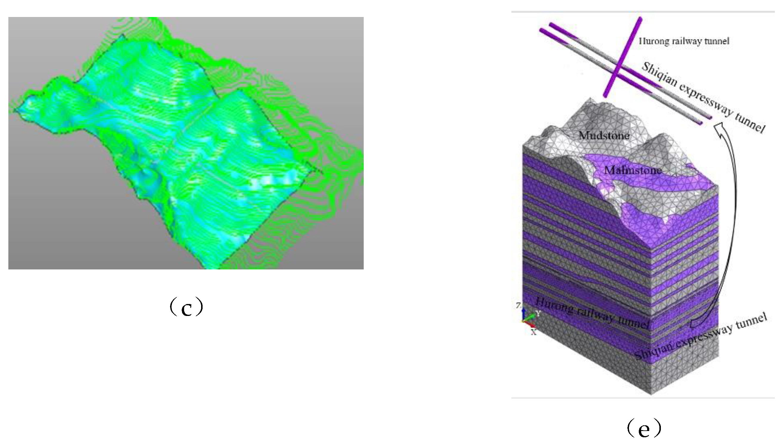
3.1. Finite Element Calculation Model
3.2. Finite Element Calculation Parameters
3.2.1. Static Loads for New Tunnel Excavation
- (1)
- The corresponding rock properties are assigned to the strata and the initial ground stress field is balanced. There is no influence of tectonic joints in the cross-section tunnel project, and the ground stress is considered according to the initial self-gravitational stress field.
- (2)
- Simulate the excavation of the whole section of the existing railroad tunnel, apply initial support and secondary lining, and zero the displacement field.
- (3)
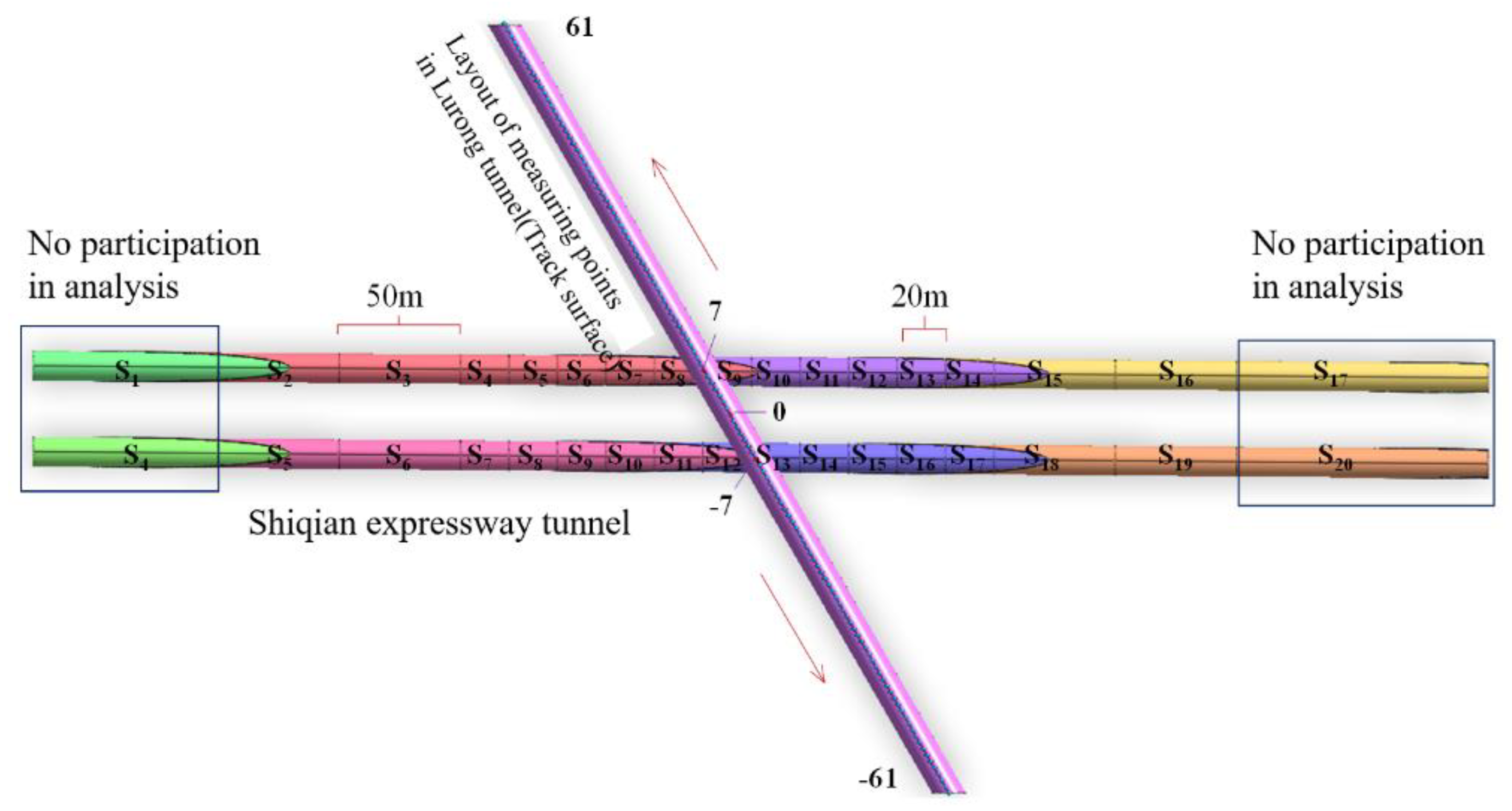
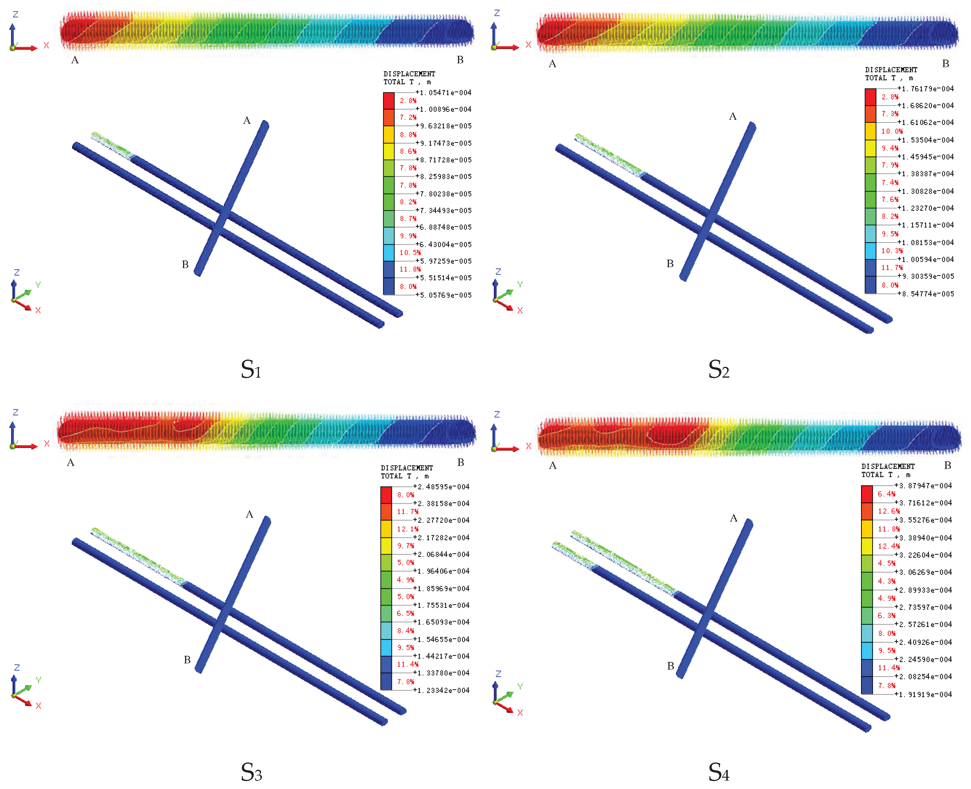
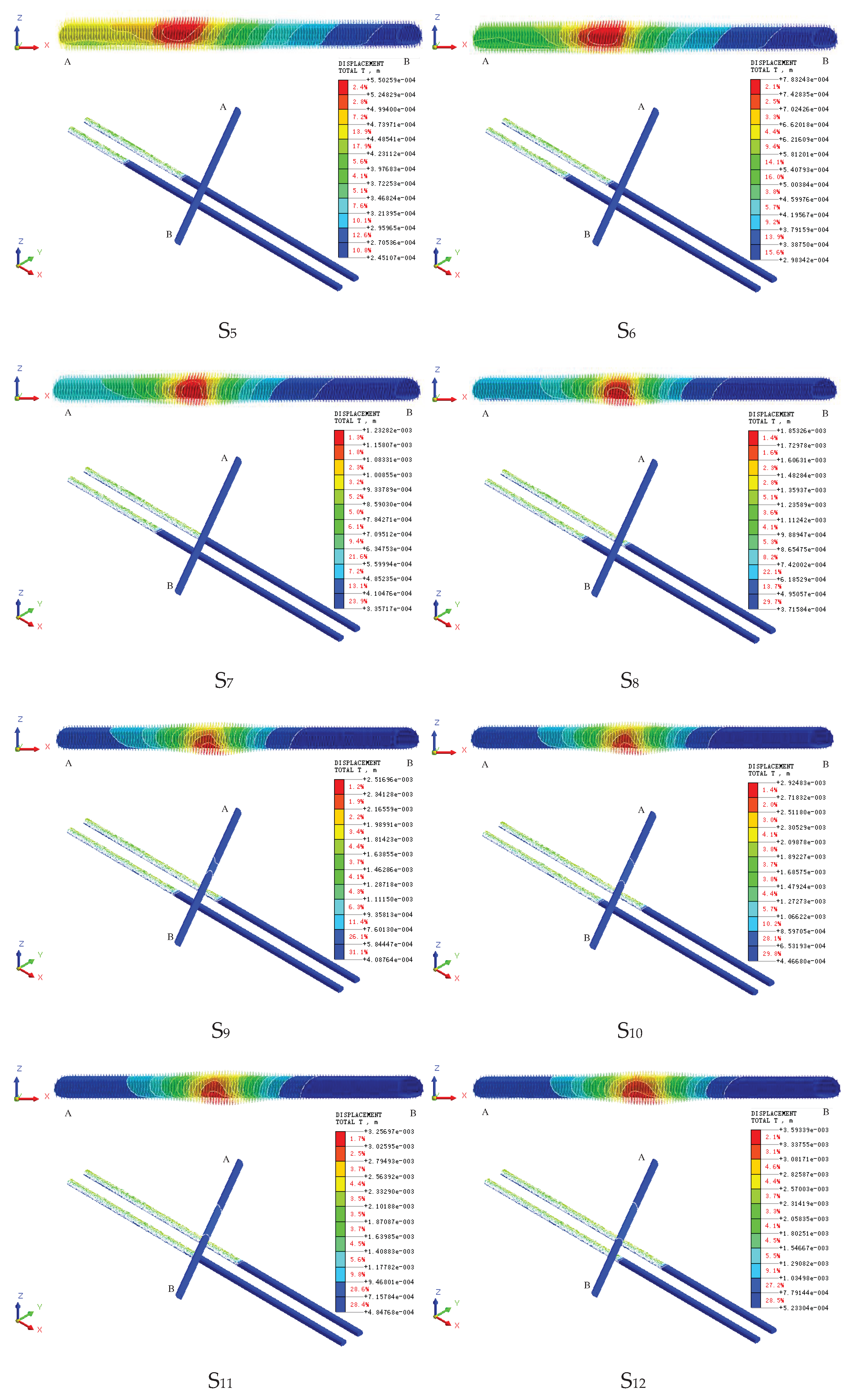
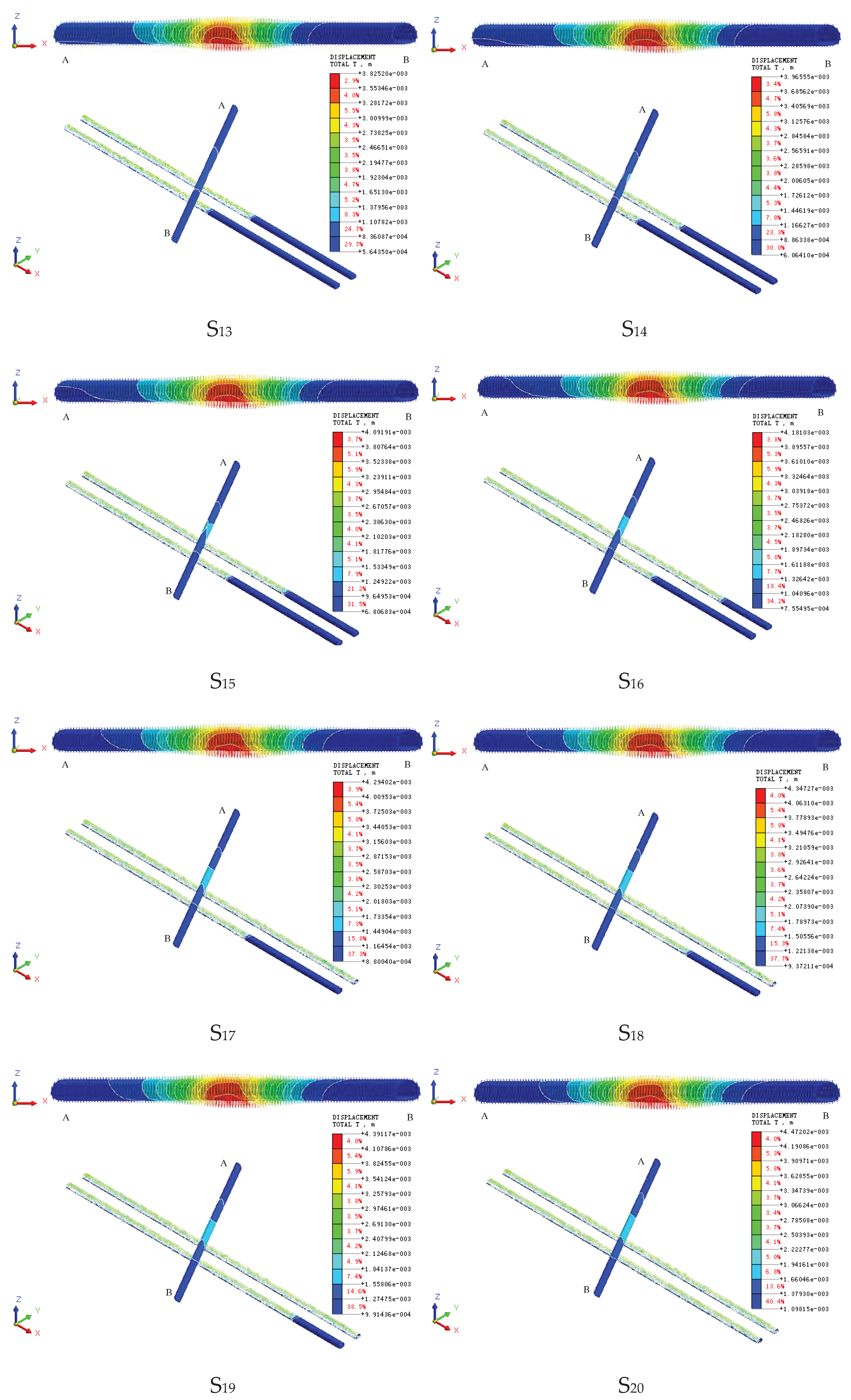
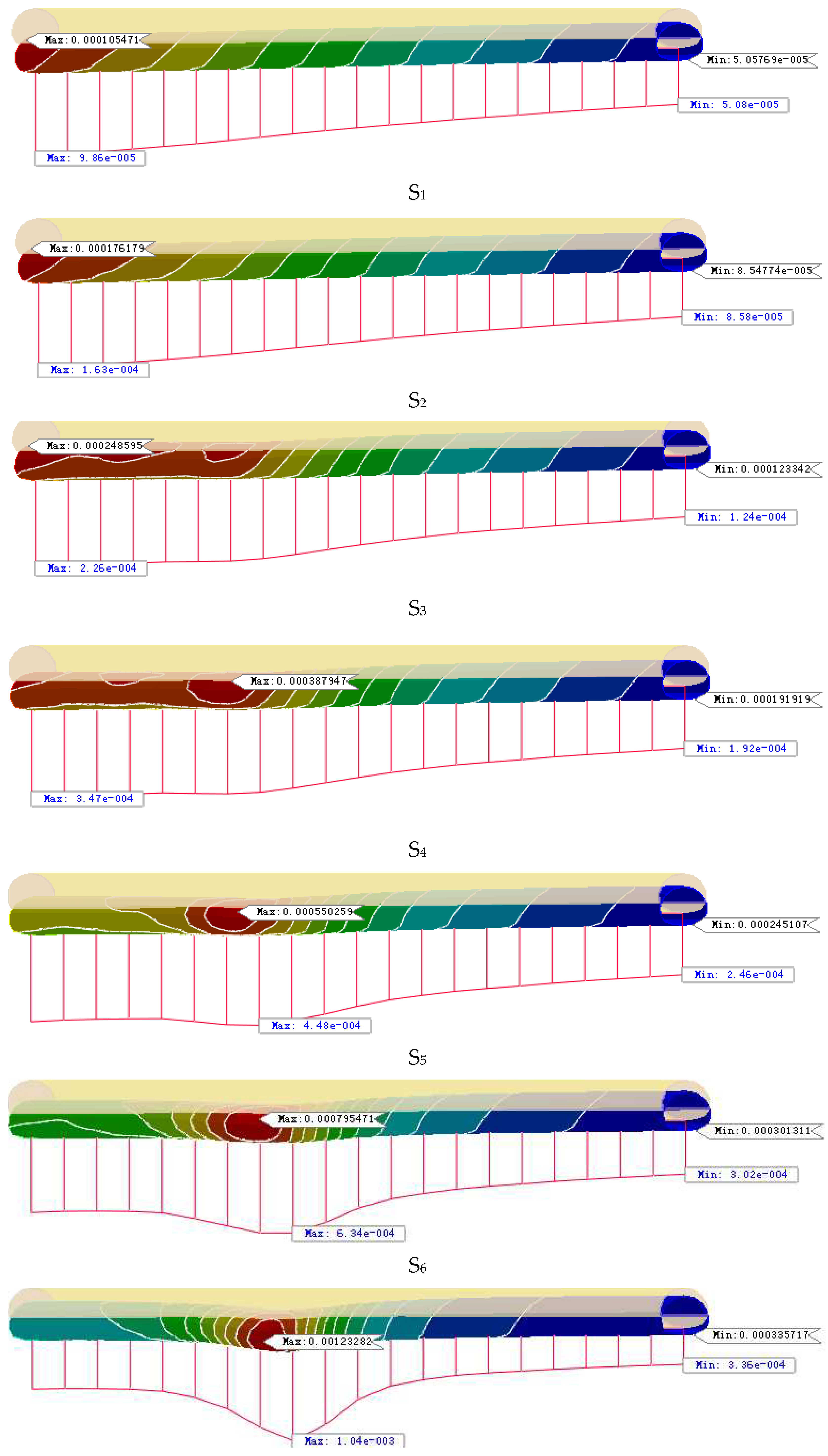
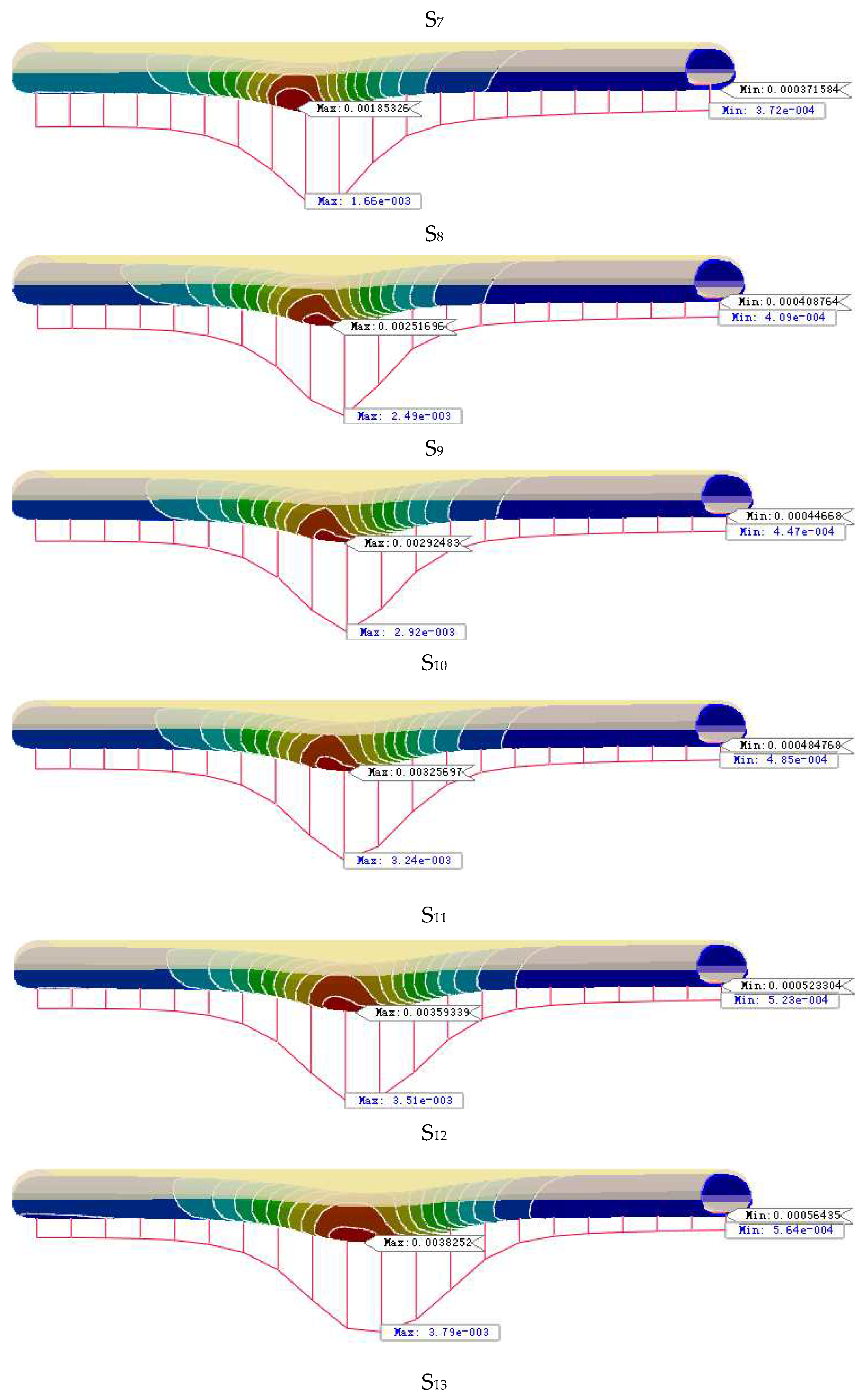
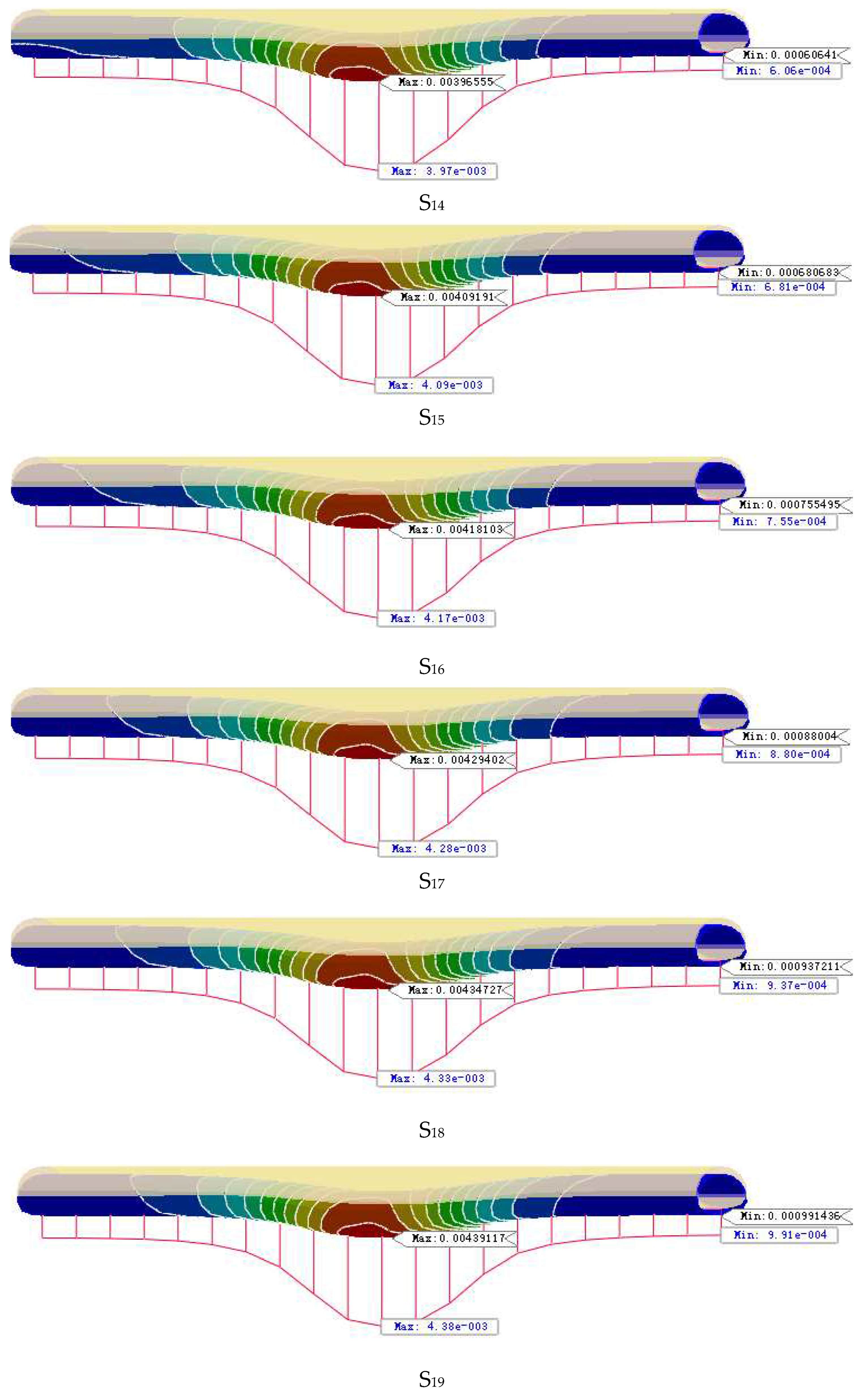
- Excavation of new highway tunnel. Tunnel each excavation footage of 2m, after excavation for the initial support and secondary lining, in order to facilitate data analysis for multiple excavation steps as a whole encapsulated into different data results extracted when the step Si. set the left side of the tunnel for the first excavation of the tunnel, from the inlet (left) to the exit (right) excavation, the right side of the tunnel for the excavation after the front and back of the tunnel difference of 3 Si, Si No. for the S1, S2, S3. S20, ......S20. The left hole S1 and S17, the right hole S4 and S20 are the time step of going to the boundary effect, which is 90m respectively. left hole S2=S3=S15=S16=50m,S4=S5=S6=S7=S8=S9=S10=S11=S12=S13=S14=20m.right hole S5=S6=S18=S19=S14=20m. S6=S18=S19=50m, S7=S8=S9=S10=S11=S12=S13=S14=S15=S16=S17=20m as shown in Figure 6.
- (4)
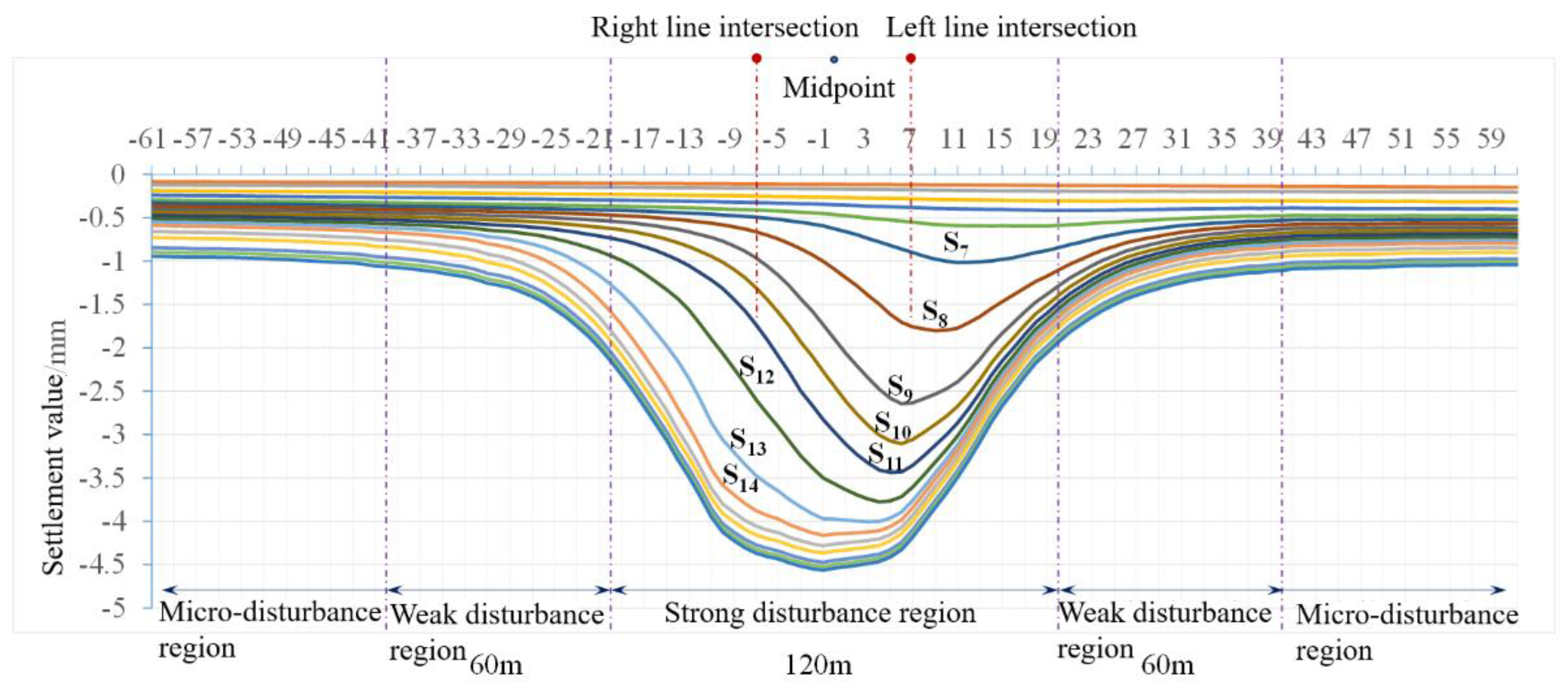
- Layout of monitoring points in existing tunnels. Along the Hurong Tunnel floor layout measurement points, tunnel left and right intersection of the center of the line is set as 0 measurement points, to the left hole extension line layout 0 ~ 61 measurement points, to the right hole extension line layout 0 ~ -61 measurement points measurement point interval distance of 3m, the 7th measurement point for the left line of the intersection, the -7th measurement point for the right line of the intersection.
3.2.2. Dynamic Blasting Loads for New Tunnels
- (1)
- Boundary conditions
- (2)
- Analysis of results
- (3)
- Time course analysis
- (1)
- Boundary conditions
- (2)
- Dynamic load
3.2.3. Existing Tunnel Operational Loads
- (1)
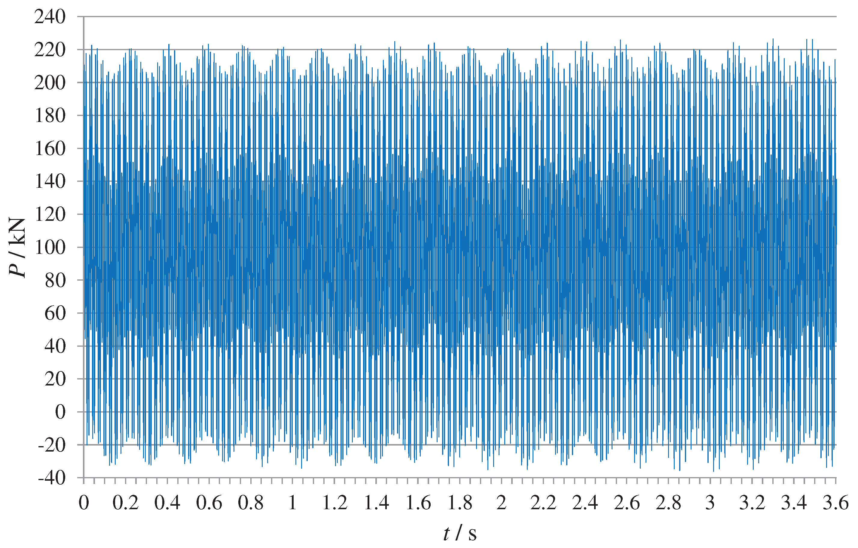
- Train dynamic load
4. Results
4.1. New Tunnel Excavation
4.2. New Tunnel Blasting
4.3. Existing Tunnel Operation
4.4. Impact Area Determination
5. Conclusions and Discussion
- (1)
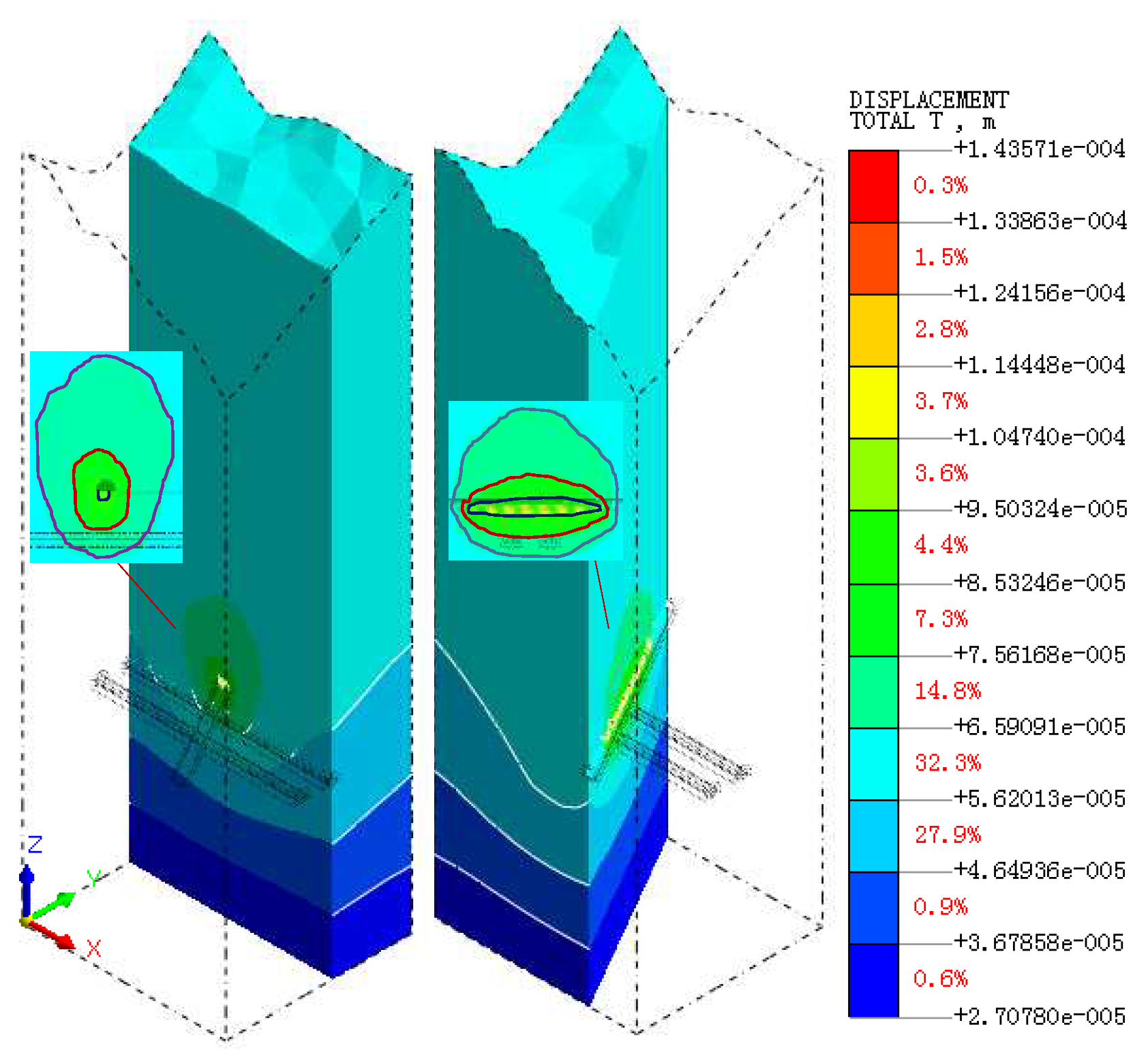
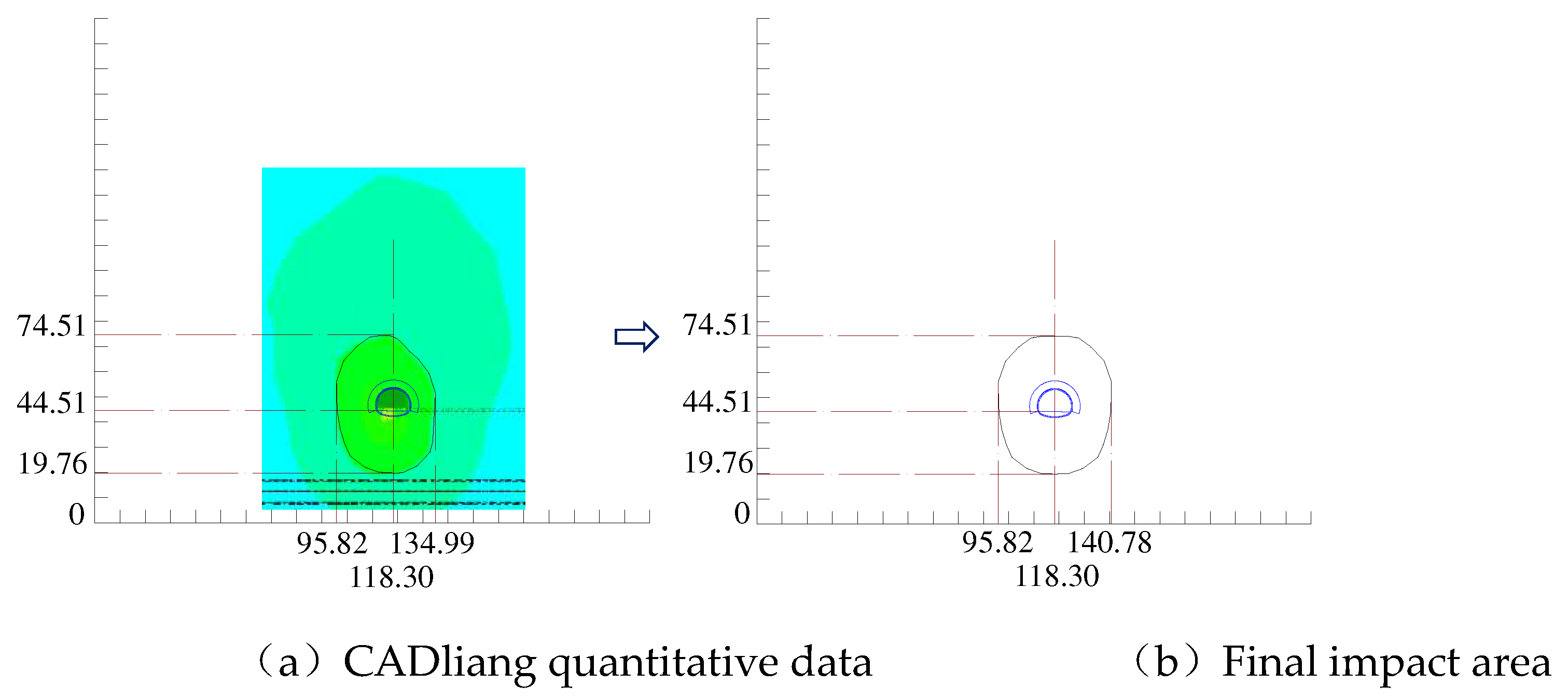
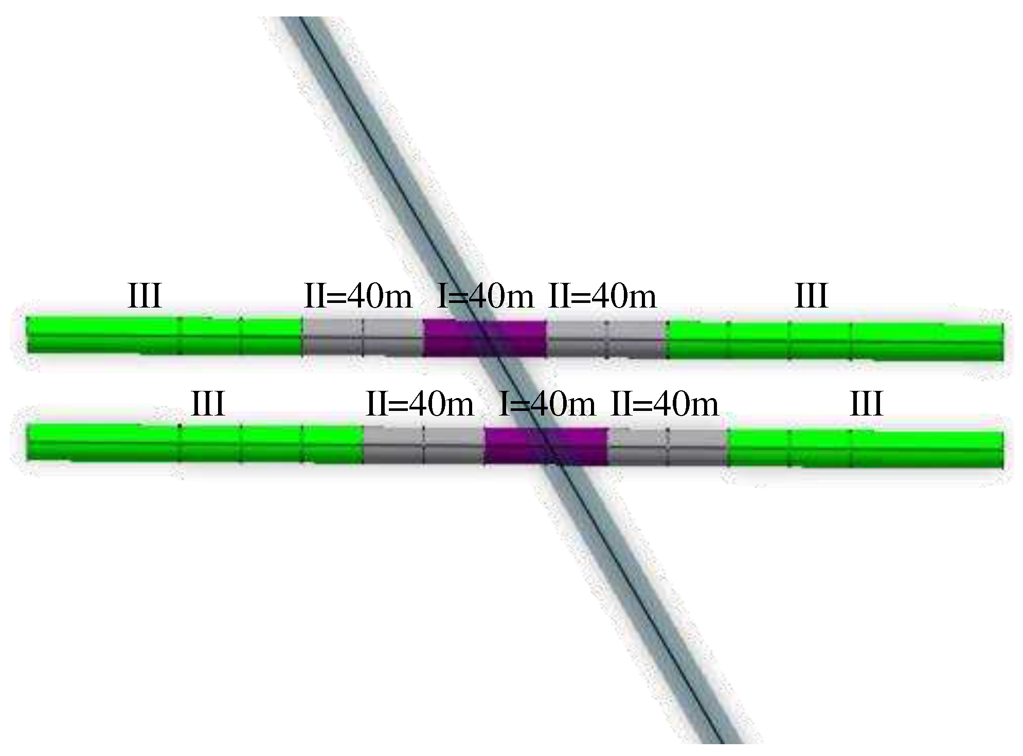
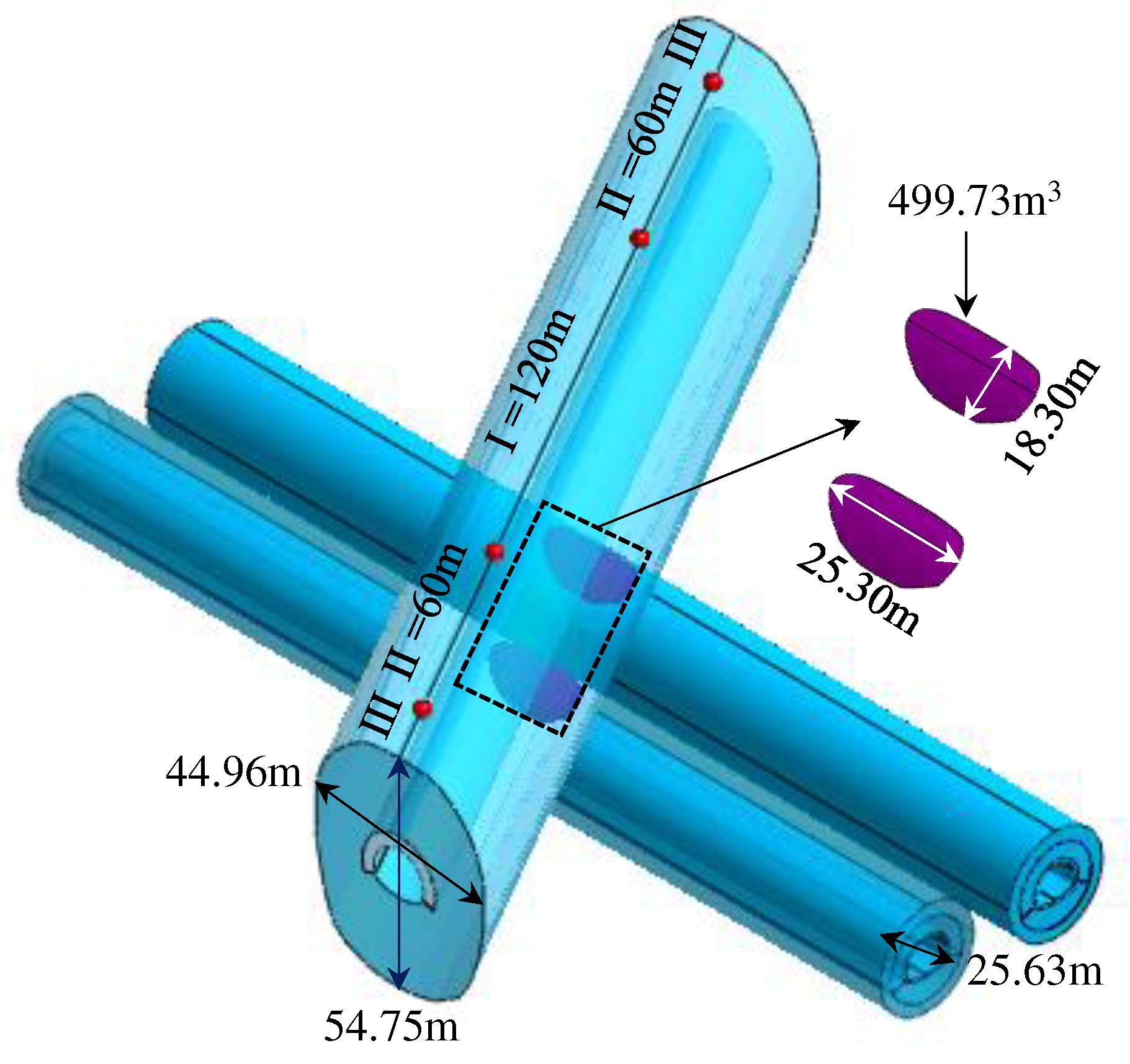
- The region of influence of the static load of new tunnel excavation on the existing tunnel. Existing tunnels from the center of the intersection to both sides of 120m for the strong disturbance area, strong disturbance area on both sides of 60m for the weak disturbance area, and other micro-disturbance area; intersection of the center of both sides of 40m for the new tunnel excavation of the strong disturbance area, strong disturbance area on both sides of 40m for the weak disturbance area, and other micro-disturbance area.
- (2)
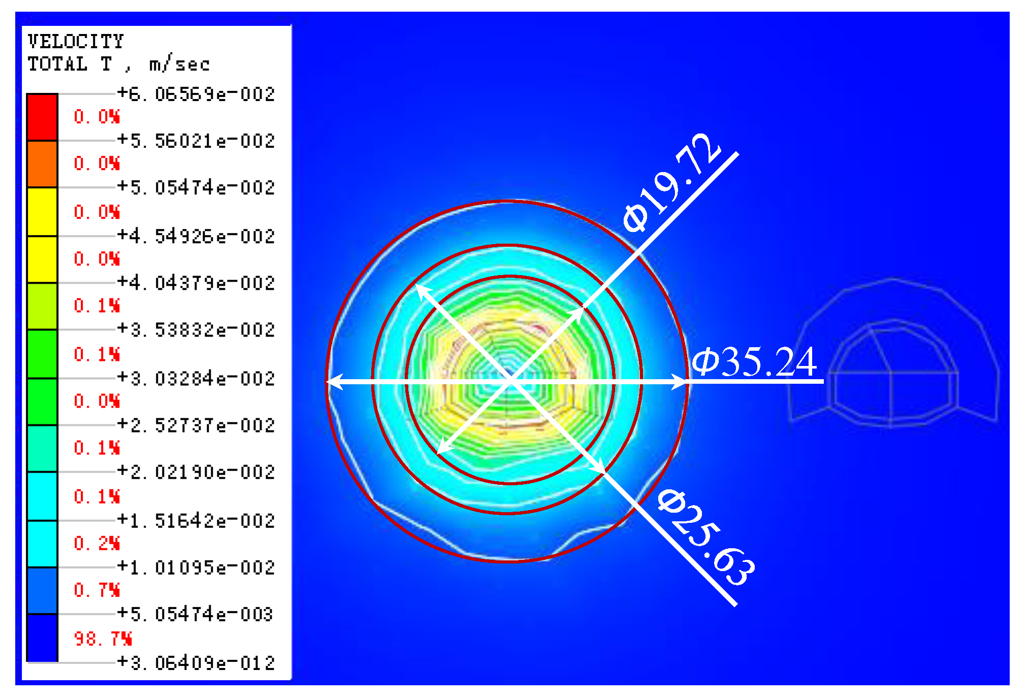
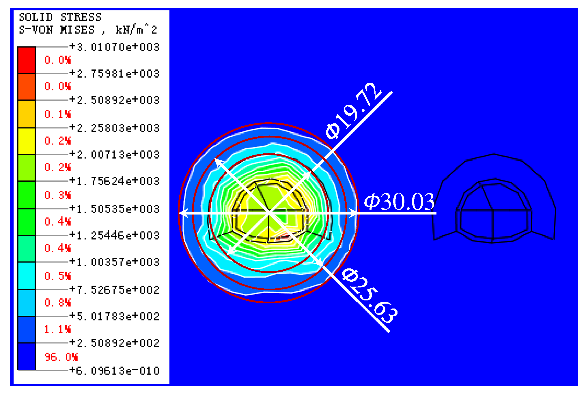
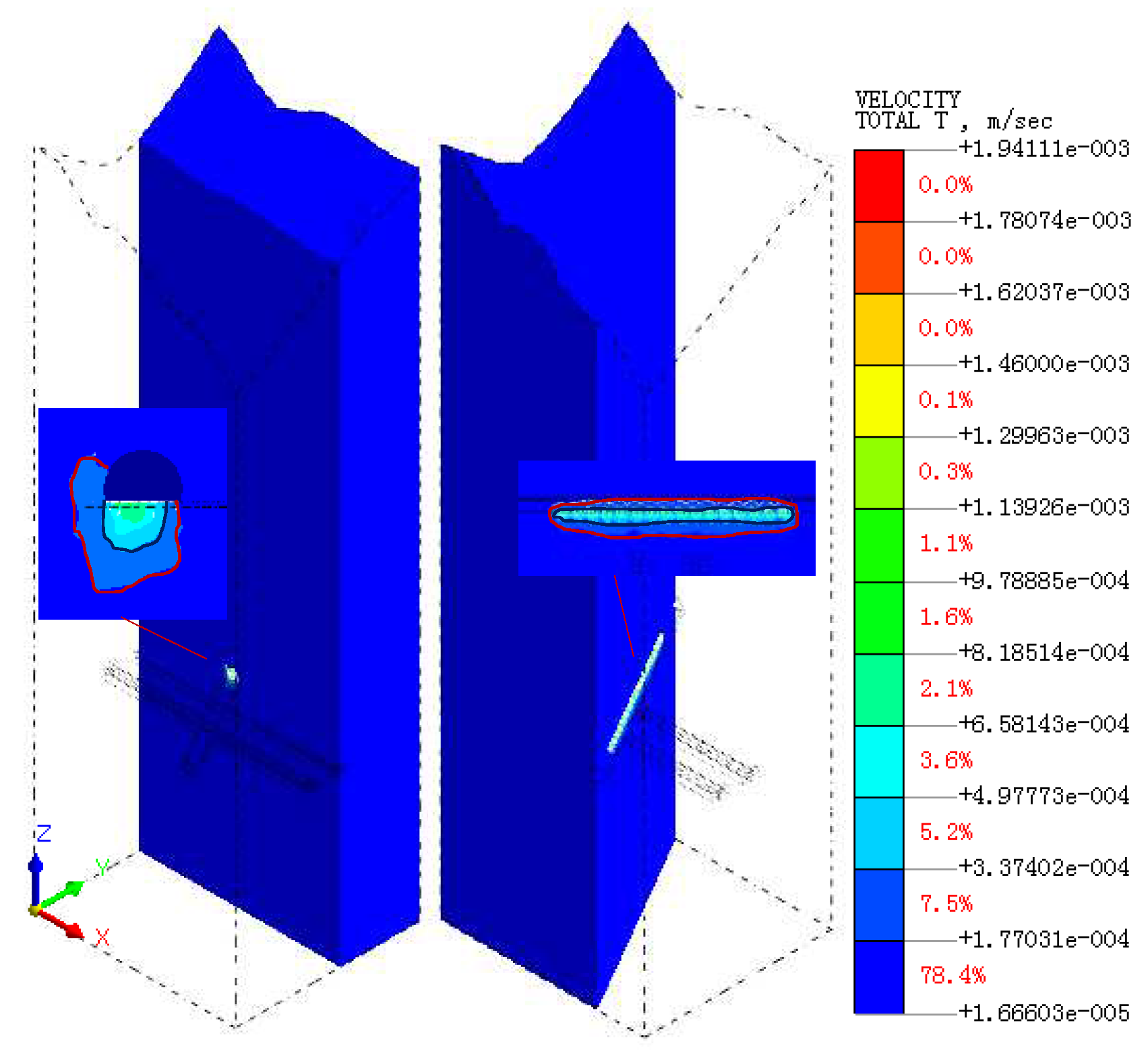
- New tunnel excavation blasting dynamic load impact area. Tunnel section in the center of the reference point, 25.63m diameter circle for the new tunnel excavation blasting dynamic load impact area.
- (3)
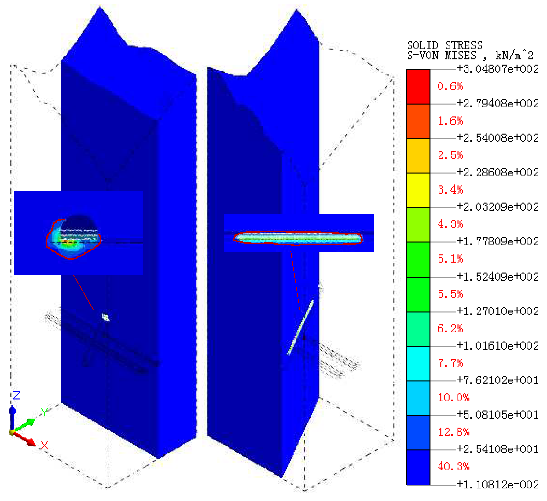
- the existing tunnel train running dynamic load impact area. The center of the existing tunnel track surface as a reference, the impact area is oval, the long axis of 54.75m, the short axis of 44.96m.
- (4)
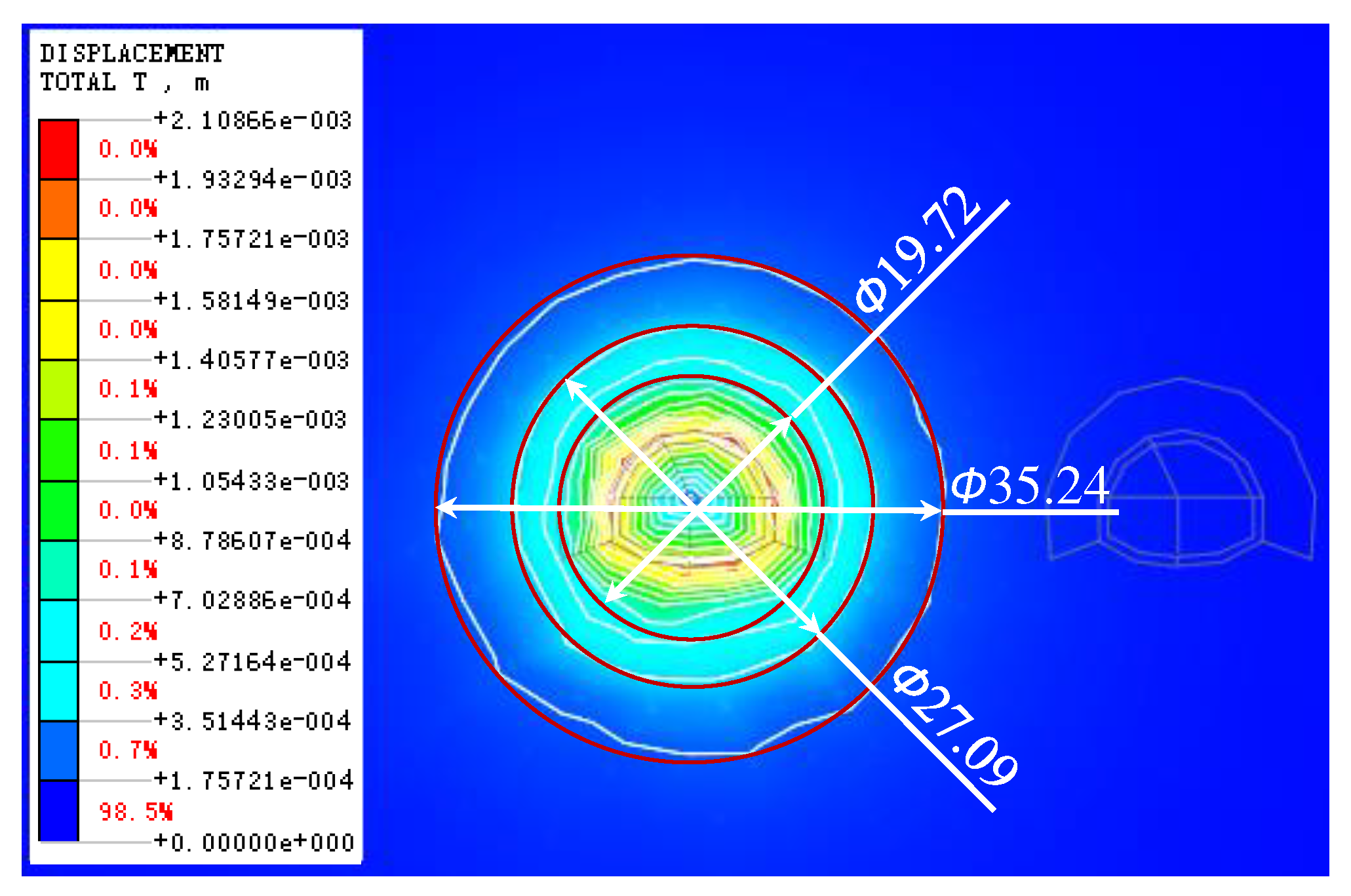
- Overlapping influence area. The dynamic load impact area of the new tunnel blasting excavation and the dynamic load impact area of the existing tunnel train operation have a heteromorphic superimposed impact area of 25.30m in length, 18.30m in width and 499.73m3 in volume.
Author Contributions
Funding
Institutional Review Board Statement
Informed Consent Statement
Data Availability Statement
Conflicts of Interest
References
- CHEN Z L, CHEN J Y, LIU H, et al. Present status and development trends of underground space in Chinese cities: Evaluation and analysis [J]. Tunnelling and Underground Space Technology, 2018, 71: 253-70. [CrossRef]
- DEBROCK S, VAN ACKER M, ADMIRAAL H. Design recommendations for sustainable urban underground spaces [J]. Tunnelling and Underground Space Technology, 2023, 140. [CrossRef]
- VON DER TANN L, STERLING R, ZHOU Y X, et al. Systems approaches to urban underground space planning and management - A review [J]. Underground Space, 2020, 5(2): 144-66. [CrossRef]
- CHENG H Z, CHEN J, CHEN G L. Analysis of ground surface settlement induced by a large EPB shield tunnelling: a case study in Beijing, China [J]. Environmental Earth Sciences, 2019, 78(20). [CrossRef]
- ISLAM M S, ISKANDER M. Twin tunnelling induced ground settlements: A review [J]. Tunnelling and Underground Space Technology, 2021, 110. [CrossRef]
- SHI J W, NG C W W, CHEN Y H. A simplified method to estimate three-dimensional tunnel responses to basement excavation [J]. Tunnelling and Underground Space Technology, 2017, 62: 53-63. [CrossRef]
- XIE X Y, YANG Y B, JI M. Analysis of ground surface settlement induced by the construction of a large-diameter shield-driven tunnel in Shanghai, China [J]. Tunnelling and Underground Space Technology, 2016, 51: 120-32. [CrossRef]
- WENG X L, SUN Y F, YAN B H, et al. Centrifuge testing and numerical modeling of tunnel face stability considering longitudinal slope angle and steady state seepage in soft clay [J]. Tunnelling and Underground Space Technology, 2020, 101. [CrossRef]
- YIN X S, CHEN R P, MENG F Y. Influence of seepage and tunnel face opening on face support pressure of EPB shield [J]. Computers and Geotechnics, 2021, 135. [CrossRef]
- ZOU J F, QIAN Z H. Face-Stability Analysis of Tunnels Excavated below Groundwater Considering Coupled Flow Deformation [J]. International Journal of Geomechanics, 2018, 18(8). [CrossRef]
- LI Y Q, ZHANG W G. Investigation on passive pile responses subject to adjacent tunnelling in anisotropic clay [J]. Computers and Geotechnics, 2020, 127. [CrossRef]
- NEMATOLLAHI M, DIAS D. Three-dimensional numerical simulation of pile-twin tunnels interaction - Case of the Shiraz subway line [J]. Tunnelling and Underground Space Technology, 2019, 86: 75-88. [CrossRef]
- PHUTTHANANON C, LERTKULTANON S, JONGPRADIST P, et al. Numerical investigation on the responses of existing single piles due to adjacent twin tunneling considering the lagging distance [J]. Underground Space, 2023, 11: 171-88. [CrossRef]
- FANG Q, ZHANG D L, LI Q Q, et al. Effects of twin tunnels construction beneath existing shield-driven twin tunnels [J]. Tunnelling and Underground Space Technology, 2015, 45: 128-37. [CrossRef]
- NG C W W, FONG K Y, LIU H L. The effects of existing horseshoe-shaped tunnel sizes on circular crossing tunnel interactions: Three-dimensional numerical analyses [J]. Tunnelling and Underground Space Technology, 2018, 77: 68-79. [CrossRef]
- YIN M L, JIANG H, JIANG Y S, et al. Effect of the excavation clearance of an under-crossing shield tunnel on existing shield tunnels [J]. Tunnelling and Underground Space Technology, 2018, 78: 245-58. [CrossRef]
- CHAKERI H, OZCELIK Y, UNVER B. Effects of important factors on surface settlement prediction for metro tunnel excavated by EPB [J]. Tunnelling and Underground Space Technology, 2013, 36: 14-23. [CrossRef]
- GUE C Y, WILCOCK M J, ALHADDAD M M, et al. Tunnelling close beneath an existing tunnel in clay - perpendicular undercrossing [J]. Geotechnique, 2017, 67(9): 795-807. [CrossRef]
- AVGERINOS V, POTTS D M, STANDING J R. Numerical investigation of the effects of tunnelling on existing tunnels [J]. Geotechnique, 2017, 67(9): 808-22. [CrossRef]
- CHEN R P, LIN X T, KANG X, et al. Deformation and stress characteristics of existing twin tunnels induced by close-distance EPBS under-crossing [J]. Tunnelling and Underground Space Technology, 2018, 82: 468-81. [CrossRef]
- SHI J W, WANG Y, NG C W W. Three-Dimensional Centrifuge Modeling of Ground and Pipeline Response to Tunnel Excavation [J]. Journal of Geotechnical and Geoenvironmental Engineering, 2016, 142(11). [CrossRef]
- LIN X T, CHEN R P, WU H N, et al. Deformation behaviors of existing tunnels caused by shield tunneling undercrossing with oblique angle [J]. Tunnelling and Underground Space Technology, 2019, 89: 78-90. [CrossRef]
- NG C W W, WONG Y Y A, SHAKEEL M. Effects of the skew angle of new tunneling on an existing tunnel: three-dimensional centrifuge and numerical modeling [J]. Canadian Geotechnical Journal, 2022. [CrossRef]
- SHIN J H, MOON H G, CHAE S E. Effect of blast-induced vibration on existing tunnels in soft rocks [J]. Tunnelling and Underground Space Technology, 2011, 26(1): 51-61. [CrossRef]
- ZHAO H B, LONG Y, LI X H, et al. Experimental and numerical investigation of the effect of blast-induced vibration from adjacent tunnel on existing tunnel [J]. Ksce Journal of Civil Engineering, 2016, 20(1): 431-9. [CrossRef]
- TIAN X X, SONG Z P, WANG J B. Study on the propagation law of tunnel blasting vibration in stratum and blasting vibration reduction technology [J]. Soil Dynamics and Earthquake Engineering, 2019, 126. [CrossRef]
- DUAN B F, GONG W Z, TA G S, et al. Influence of Small, Clear Distance Cross-Tunnel Blasting Excavation on Existing Tunnel below [J]. Advances in Civil Engineering, 2019, 2019. [CrossRef]
- CAO F, ZHANG S, LING T H. Blasting-Induced Vibration Response of the Transition Section in a Branching-Out Tunnel and Vibration Control Measures [J]. Advances in Civil Engineering, 2020, 2020. [CrossRef]
- RUAN J B, WANG T H, ZHAO Z K, et al. Discussion on Blasting Vibration Velocity of Deep Rock Mass Considering Thickness of Overlying Soil Layer [J]. Periodica Polytechnica-Civil Engineering, 2023. [CrossRef]
- GHAREHDASH S, BARZEGAR M. Numerical modeling of the dynamic behaviour of tunnel lining in shield tunneling [J]. Ksce Journal of Civil Engineering, 2015, 19(6): 1626-36. [CrossRef]
- MA M, LIU W N, QIAN C Y, et al. Study of the train-induced vibration impact on a historic Bell Tower above two spatially overlapping metro lines [J]. Soil Dynamics and Earthquake Engineering, 2016, 81: 58-74. [CrossRef]
- LAI J X, WANG K Y, QIU J L, et al. Vibration Response Characteristics of the Cross Tunnel Structure [J]. Shock and Vibration, 2016, 2016. [CrossRef]
- HUANG Q, HUANG H W, YE B, et al. Dynamic response and long-term settlement of a metro tunnel in saturated clay due to moving train load [J]. Soils and Foundations, 2017, 57(6): 1059-75. [CrossRef]
- YAN Q X, SONG L Y, CHEN H, et al. Dynamic Response of Segment Lining of Overlapped Shield Tunnels Under Train-Induced Vibration Loads [J]. Arabian Journal for Science and Engineering, 2018, 43(10): 5439-55. [CrossRef]
- DONG J, ZHONG S, WANG H L, et al. Dynamic response characteristics of crossing tunnels under heavy-haul train loads [J]. Geomechanics and Engineering, 2020, 20(2): 103-12. [CrossRef]
- ZHANG X, ZHANG M X, JAVADI A A. Influence of a Super-Large Diameter Shield Tunnel Excavation on the Lining Structure of the Metro Lines in Operation [J]. Iranian Journal of Science and Technology-Transactions of Civil Engineering, 2023. [CrossRef]
- GALLI G, GRIMALDI A, LEONARDI A. Three-dimensional modelling of tunnel excavation and lining [J]. Computers and Geotechnics, 2004, 31(3): 171-83. [CrossRef]
- WANG W H, WANG L L, DU Y Z, et al. Numerical and experimental analysis on motion performance of new sandglass-type floating body in waves [J]. Marine Structures, 2016, 46: 56-77. [CrossRef]
- YANG C S, MO H H, CHEN J S, et al. Influence of Seismic Loading on Segment Opening of a Shield Tunnel [J]. Scientific World Journal, 2014. [CrossRef]
- LAI J X, GUO C X, QIU J L, et al. Static Analytical Approach of Moderately Thick Cylindrical Ribbed Shells Based on First-Order Shear Deformation Theory [J]. Mathematical Problems in Engineering, 2015, 2015. [CrossRef]
- NEJATI H R, AHMADI M, HASHEMOLHOSSEINI H. Numerical analysis of ground surface vibration induced by underground train movement [J]. Tunnelling and Underground Space Technology, 2012, 29: 1-9. [CrossRef]
- SHI C H, ZHAO Y W, ZHAO C Y, et al. Water-Sealed Blasting Control Measures of the Metro Station Undercrossing Existing Structures in Ultra-Close Distances: A Case Study [J]. Frontiers in Earth Science, 2022, 10. [CrossRef]
- WU X D, GONG M, WU H J, et al. Vibration reduction technology and the mechanisms of surrounding rock damage from blasting in neighborhood tunnels with small clearance [J]. International Journal of Mining Science and Technology, 2023, 33(5): 625-37. [CrossRef]
- YE F, HE C, WANG S M, et al. Landscape design of mountain highway tunnel portals in China [J]. Tunnelling and Underground Space Technology, 2012, 29: 52-68. [CrossRef]
- LAI J X, MAO S, QIU J L, et al. Investigation Progresses and Applications of Fractional Derivative Model in Geotechnical Engineering [J]. Mathematical Problems in Engineering, 2016, 2016. [CrossRef]
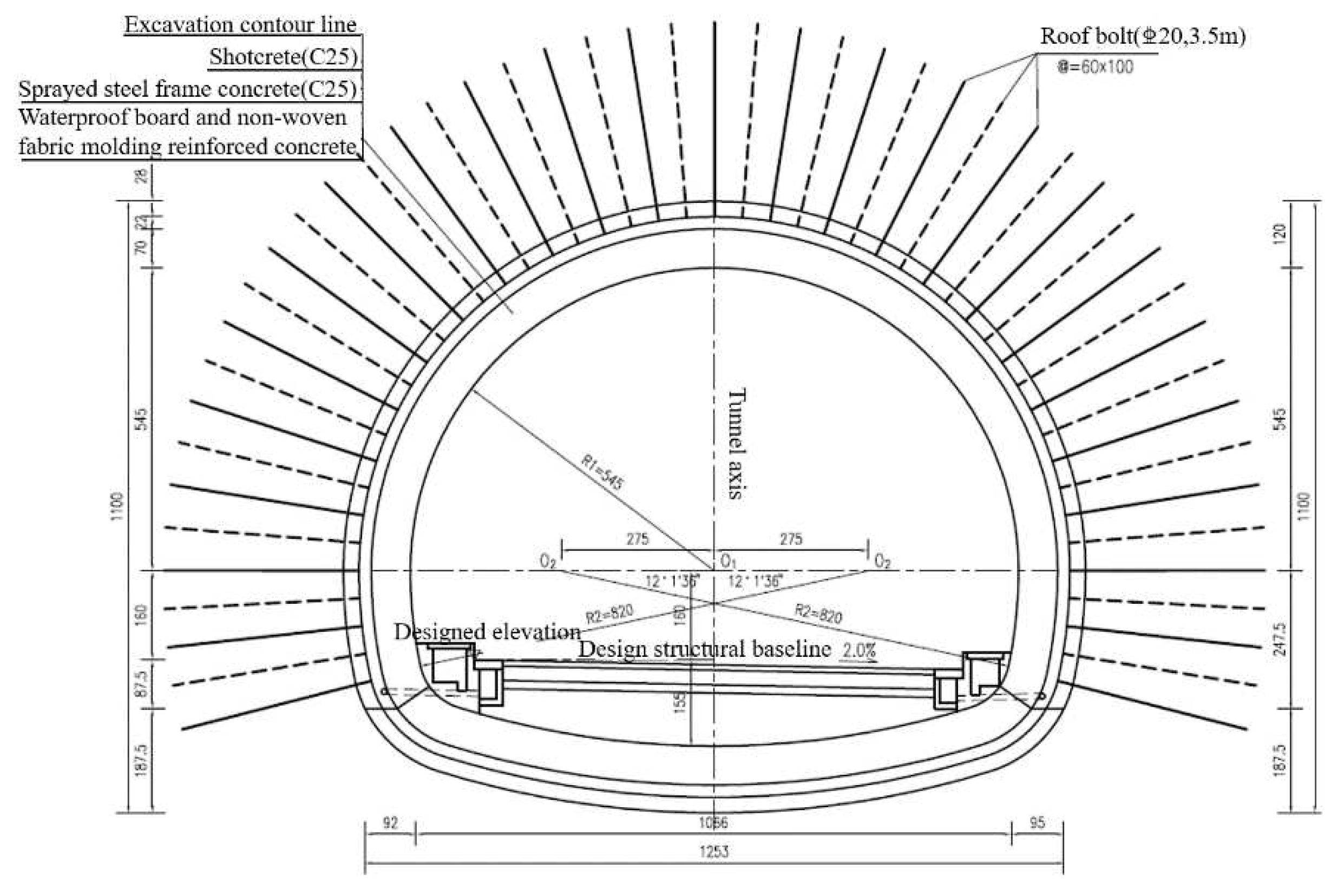


| Sports Event | Tunnel Support Parameters of Shiqian Expressway | Hurong Railway Tunnel Support Parameters | |
|---|---|---|---|
| Initial support | C25 spray concrete | 28cm | 23cm |
| Φ6.5 steel mesh | @20×20cm | @20×20cm | |
| Initial support reinforcement measures | 22a I-beam @60cm closed into a ring | 22a I-beam @60cm closed into a ring | |
| Sprayed steel-framed concrete | System anchor | @60×100cm, L=3.5m, C20 flux-coiled anchors | @120×100cm, L=3.5m, C20 flux-coiled anchors |
| C25 spray concrete | 22cm | 20cm | |
| Steel frame | 16a I-beam @60cm closed into a ring | 16a I-beam @100cm closed into a ring | |
| Secondary lining | 70cm C30 reinforced concrete | 45cm C35 reinforced concrete | |
| Vault | 70cm C30 reinforced concrete | 50cm C35 reinforced concrete | |
| Ancillary construction measures | T76L self-propelled anchor + small conduit in advance | T76L self-propelled anchor + small conduit in advance | |
| Enterprise | Materials | E(GPa) | μ | γ(kN/m3) | c(MPa) | φ(°) | σ(MPa) |
|---|---|---|---|---|---|---|---|
| Stratum | Malmstone | 5.09 | 0.31 | 23.13 | 2.25 | 35.82 | 8.90 |
| Mudstone | 2.15 | 0.33 | 23.89 | 1.03 | 33.48 | 3.84 | |
| Highway tunnel | anchor support | 42 | 0.2 | ||||
| steel-frame grating support | 52 | 0.2 | |||||
| Railway tunnel | anchor support | 31 | 0.2 | ||||
| steel-frame grating support | 43 | 0.2 |
| Rock layers (top to bottom) | Model X, Y, Z direction rock reaction coefficient (t/m3) | ||||
|---|---|---|---|---|---|
| kLXh | kRXh | kFYh | kBYh | kZv | |
| Mudstone | 2665.52 | 4387.63 | 3145.71 | 2432.20 | |
| Malmstone | 7244.13 | 8970.20 | 7759.39 | 7153.64 | |
| Mudstone | 3000.16 | 3126.16 | 2946.43 | 2907.13 | |
| Malmstone | 5915.44 | 5884.53 | 5710.24 | 5710.24 | |
| Mudstone | 4530.42 | 4527.31 | 4384.49 | 4384.49 | |
| Malmstone | 9279.97 | 9156.92 | 8921.78 | 8921.78 | |
| Mudstone | 3433.82 | 3471.77 | 3330.95 | 3330.95 | |
| Malmstone | 9418.76 | 9440.04 | 9170.55 | 9170.55 | |
| Mudstone | 3778.67 | 4061.60 | 3665.52 | 3665.52 | |
| Malmstone | 12121.47 | 12114.00 | 11728.72 | 11728.72 | |
| Mudstone | 2872.95 | 2876.63 | 2781.49 | 2781.49 | |
| Malmstone | 8071.31 | 8006.92 | 7782.58 | 7782.58 | |
| Mudstone | 2849.02 | 3341.86 | 2944.74 | 2944.74 | |
| Malmstone | 10695.17 | 11704.80 | 10214.62 | 10214.62 | |
| Mudstone | 5055.50 | 3273.70 | 3833.84 | 3833.84 | |
| Malmstone | 16257.58 | 17026.51 | 16334.96 | 16334.96 | |
| Mudstone | 4388.29 | 4656.22 | 4334.61 | 4334.61 | |
| Malmstone | 14776.82 | 14146.10 | 14016.62 | 14016.62 | |
| Mudstone | 7913.75 | 8064.80 | 8000.96 | 8000.96 | |
| Malmstone | 7416.49 | 7348.26 | 7214.18 | 7214.18 | |
| Mudstone | 4157.90 | 4093.52 | 3915.15 | 3915.15 | |
| Malmstone | 10895.32 | 11533.88 | 10782.67 | 10782.67 | |
| Mudstone | 3940.98 | 3941.80 | 3755.93 | 3755.93 | |
| Malmstone | 11277.14 | 10721.60 | 10633.81 | 10633.81 | |
| Mudstone | 6106.59 | 6398.02 | 6045.57 | 6045.57 | |
| Malmstone | 6596.91 | 6338.03 | 6255.26 | 6255.26 | |
| Mudstone | 2212.34 | 2078.98 | 2073.10 | 2073.10 | 1556.58 |
| Rock Stratum | cp | cs |
|---|---|---|
| Mudstone | 278.584 | 140.3275 |
| Malmstone | 407.594 | 212.2705 |
| Distance from the Centerline R (M) |
The Maximum Amount of Explosive Charge at a Time Q (Kg) |
Circular Footage (M) | Mass Vibration Velocity V (cm/S) |
|---|---|---|---|
| 30 | 1.7 | 0.6 | 2.00 |
| 40 | 4.0 | 0.6 | 2.00 |
| 50 | 8.0 | 1.0 | 2.00 |
| 60 | 8.0 | 1.0 | 1.52 |
| 70 | 12 | 1.0 | 1.48 |
| 80 | 18 | 1.0 | 1.48 |
| 90 | 26 | 2.0 | 1.49 |
| 100 | 36 | 2.0 | 1.50 |
| 110 | 48 | 3.0 | 1.50 |
| 120 | 62 | 3.0 | 1.48 |
| Name of Shell Hole | Number of Millisecond Detonator Segments | Depth of Hole (m) |
Hole | Single Hole Charge (kg) |
Charge of Single Section (kg) |
|---|---|---|---|---|---|
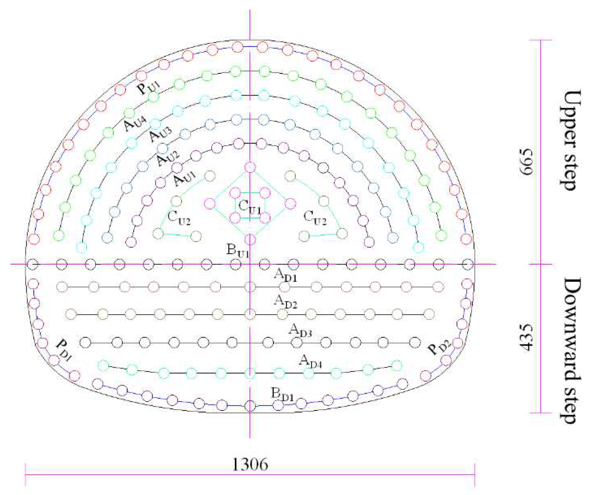
| CU1 | 1 | 1.4 | 8 | 0.8 | 6.4 |
| CU2 | 3 | 1.3 | 8 | 0.6 | 4.8 |
| AU1 | 5 | 1.1 | 16 | 0.4 | 6.4 |
| AU2 | 7 | 1.1 | 16 | 0.4 | 6.4 |
| AU3 | 9 | 1.1 | 18 | 0.4 | 7.2 |
| AU4 | 11 | 1.1 | 20 | 0.4 | 8.0 |
| PU1 | 13 | 1.1 | 26 | 0.3 | 7.8 |
| BU1 | 15 | 1.1 | 16 | 0.5 | 8.0 |
| AD1 | 1 | 1.1 | 12 | 0.6 | 7.2 |
| AD2 | 3 | 1.1 | 12 | 0.6 | 7.2 |
| AD3 | 5 | 1.1 | 13 | 0.6 | 7.8 |
| AD4 | 7 | 1.1 | 13 | 0.6 | 7.8 |
| PD1 | 9 | 1.1 | 12 | 0.4 | 4.8 |
| BD1 | 11 | 1.3 | 13 | 0.6 | 7.8 |
| subtotal | 203 | 97.6 |
Disclaimer/Publisher’s Note: The statements, opinions and data contained in all publications are solely those of the individual author(s) and contributor(s) and not of MDPI and/or the editor(s). MDPI and/or the editor(s) disclaim responsibility for any injury to people or property resulting from any ideas, methods, instructions or products referred to in the content. |
© 2023 by the authors. Licensee MDPI, Basel, Switzerland. This article is an open access article distributed under the terms and conditions of the Creative Commons Attribution (CC BY) license (http://creativecommons.org/licenses/by/4.0/).


