1. Introduction
The most commonly used procedures for determining the value of the profile shift coefficient are the so-called "equalizations", when at two characteristic points of the path of contact the values are made equal to each other, namely those are equalized.
According to Niemann's proposal, the equalization of sliding velocities means that the profile shift coefficients are determined in such a way that the sliding velocities at the boundary points of the path of contact are equal to each other [
1].
The equalization the specific slidings based on Diker's proposal means that the profile shift coefficients are determined in such a way that the specific sliding values at the limit points of the path of contact are equal to each other [
2,
3].
With regard to the mentioned methods, it can be stated that they only take into account the kinematic characteristics of the movement of the tooth profiles. The load bearing capacity has no influence on the calculations.
The calculation based on the equalization of the two-factor Almen products aspires to eliminate this problem. The method involves equalizing the product of the sliding velocity and the resulting Hertzian stress [
4].
The main problem with equalizations is that instead of testing the entire length of the path of contact, only the values of point characteristics have been tested.
This cannot ensure the finding of the extreme value or values of the examined characteristic, nor, in general, whether the value of the examined characteristic is an extreme value at path of contact limit points.
2. Method
On the basis of all this, a new method for the selection of the profile shift coefficients has been presented, with the application of which the preferred results in terms of the stresses on the teeth can be clearly determined [
5].
It is important to mention that during the examination of the manufacturing and operational problems of gears, it is not the first time that in the case of processes with spatial and temporal extension, values are not calculated with often arbitrarily selected values from the process, but the entire process is analyzed uniformly.
Such cases can be presented, among other things, in the case of a method developed to follow the spatial change of tool edge wear during operation [
6]. The cameras have been positioned in a mathematically calculated way [
7] in order to be able to perform the reconstruction from the two digitized images using the descriptive geometric method [
8]. For the adjustment of the hob of the gear connected with the curved profile worm in the resharpened state, during the examination of the relationship between the changeable axis distance and axis angle [
9], a function for the mathematically correct setting of the worm gear hob has been written at the Worm Scientific School in Miskolc [
10].
Similarly, comprehensive research has been described for the uniform determination of contact [
11], which is suitable in case of the conical worm gear drive pairs [
12] and the cylindrical curved worm gear drive pairs [
13] bearing pattern for the examination and adjustment, depending on the geometrical parameters.
The enveloping surfaces of the connected pairs of toothed elements were modelled with CAD design software [
14] and determined by self-made computer program [
15].
The accuracy of the production of cylindrical and conical helicoidal surfaces depends on the correctness of the description of the process [
16], and on additional factors, such as the wear of the machining grinding wheel [
17]. The wear of the grinding wheel during operation causes profile distortion, which makes re-profiling necessary, but this results to a decreasing centre distance and with it a changing characteristic curve [
18], which causes the necessary change of the profile of the wheel. Through all of this, with the relation between the characteristic curve and the geometric parameters, the limit of the necessary re-profiling and the inflection point of the undercut can be determined [
19].
The reverse of the procedure was also investigated, in which case the surface of the cylindrical worm with a circular arc profile is back-enveloped to create the operating surface of the grinding wheel [
20].
In order to eliminate the pitch fluctuation in the case of machining the conical worm with axis displacement, it was examined with the affine geometrical relations demonstrated with the descriptive geometry toolbox [
21]. The goal was to determine the equation of the profile curve of the drive pin in an explicit form in order to correct the pitch error [
22].
In addition to all this, the procedure presented in this article is the result of gap-filling work regarding the optimization of the profile shift factor from several points of view.
In the case of the newly developed method, the examination of the characteristics of the tooth connection was replaced by an examination covering the entire path of contact, instead of comparing point values. During the tests, the values of the special stresses (Hertzian stress, flash temperature, bending stress) were examined over the entire length of the path of contact.
The purpose of the newly developed method is to avoid typical damage and ensure preferable efficiency through the choice of profile shift coefficients.
The examination was extended to the following gear failures: bending stress (detailed calculations are presented in point 2), pitting, seizing, linear wear. The good efficiency has been achieved by minimizing the friction loss on the tooth profile, or reaching a conducive lubrication condition.
The profile shift coefficients chosen within the framework of the new method have been considered optimal if those provide the most favourable result in relation to a given criterion. The latter can be the maximum or minimum of the given characteristic.
The optimal profile shift coefficient should be interpreted as the pair of values x1, x2, which depending on the individual test criteria, can be:
the minimum of the maximum of the variable characteristic along the path of contact (bending stress, Hertzian stress, flash temperature),
the maximum of the minimum of the variable characteristic along the path of contact (lubricant film thickness),
the minimum of the given characteristic, that is, it is sufficient to generate the criterion in the form of the function f() and then determine the optimal value in the form (friction loss on the tooth profile, linear wear).
By applying the method, already in the planning period, the opportunity to determine the examined cylindrical gear geometry, that can withstand the greatest possible stress in the case of the examined cylindrical gear.
By applying the method, already in the planning period, the opportunity to determine the examined cylindrical gear geometry, that can withstand the greatest possible stress in the case of the examined cylindrical gear.
Mathematical method of tests according to various criteria: local extreme value search using the method of finite increments, in a given interpretation area.
The interpretation area of the tests is the area delimited by the undercut and tooth pointing in the case of the given gear.
3. Method of production of the bending stress function
From the point of view of presenting and evaluating the results of the calculations, it is advisable to record the data of a sample pair of gears.
After carrying out the tests according to the various objective functions for a sample gear pair (
Table 1), the profile shift coefficient value pairs that can be determined based on these principles become comparable.
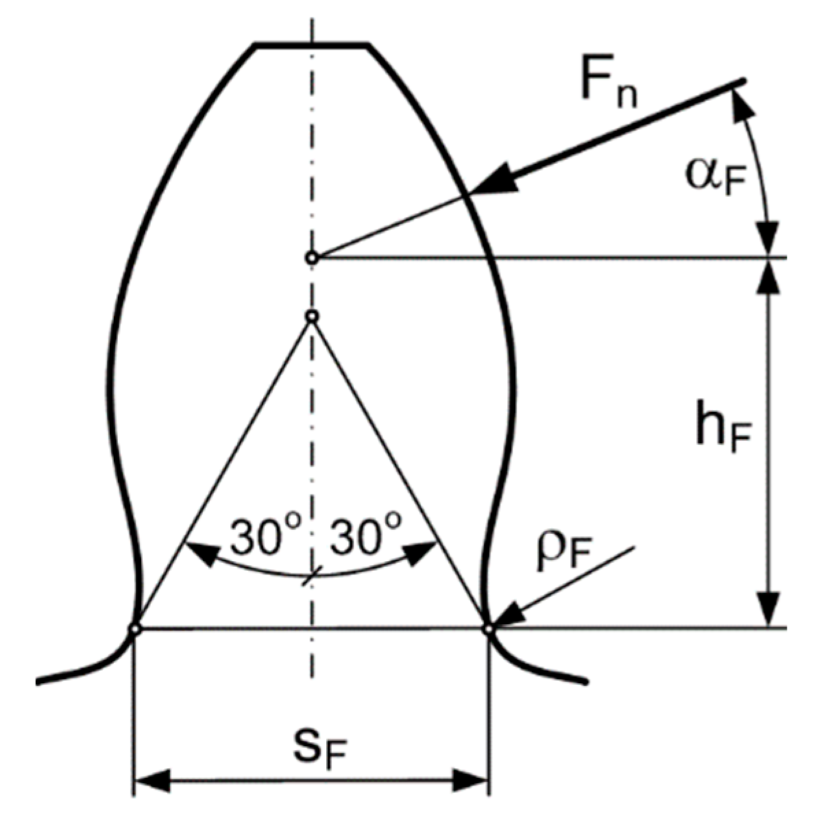
In this case, the change in the magnitude of the bending stress was examined, while the point of attack of the normal tooth force Fn moves along the entire length of the path of contact. The approximation of Hofer [
23] generally accepted and widely used today has been used for our calculations.
Figure 1 shows the Hofer model used in our calculations presenting the load on the tooth.
The bending stress in the root can be determined as follows:
where
is the value of the bending stress as a function of the linear parameter „
”,
is the change of the load along the path of contact,
is the angle determining the direction of the normal tooth force, which is the angle between the line of action of the normal tooth force
and the center line of the tooth,
is the arm of bending as a function of the linear parameter „
”,
is the thickness of the root in the critical cross-section in terms of the bowing, b is the tooth width.
For the traceability of changes along the path of contact, we introduce the linear parameter „”, which can be interpreted as its value at the limit point „A” of the path of contact, that , while at the path of contact limit point „E”: . Where and are the instantaneous radii of curvature of the pinion at the limit points of the path of contact, and, is the path of contact length.
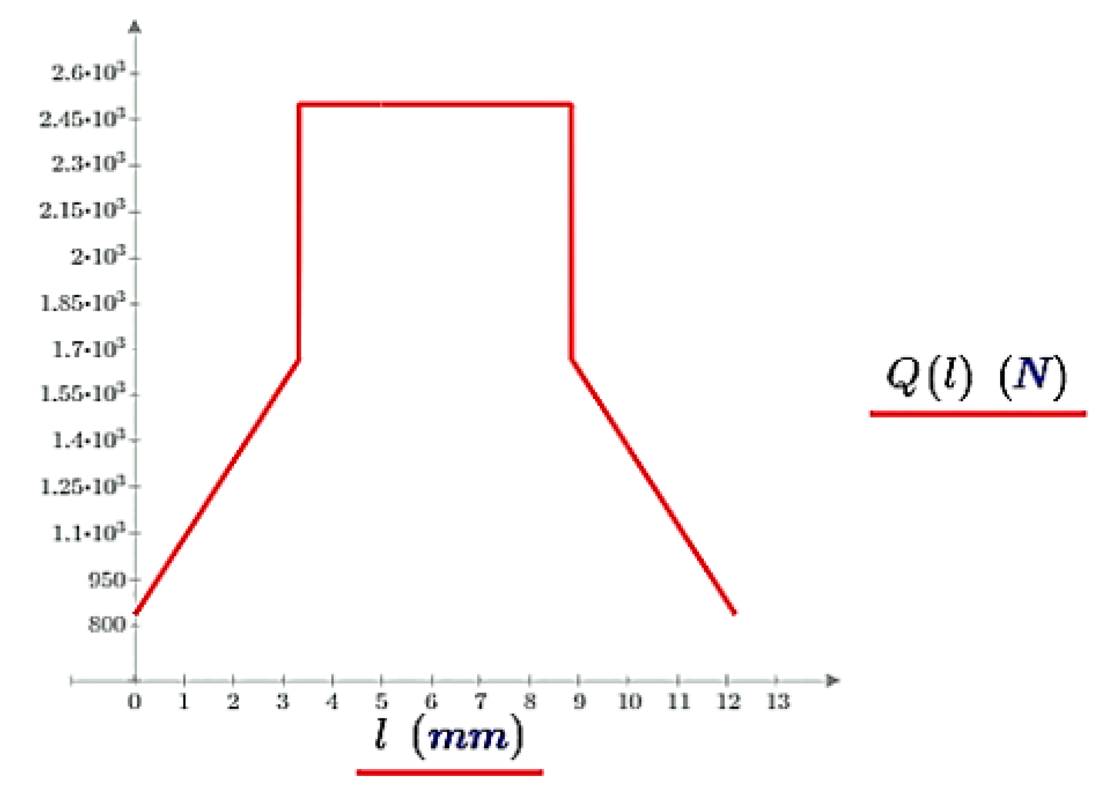
During the examinations, the following load distribution model is applicated:
At the section of connection stages of the two pairs of teeth are used:
and
while at the section of connection stage of a pair of teeth:
Figure 2.
Based on the presented load model, the load change along the path of the contact.
Figure 2.
Based on the presented load model, the load change along the path of the contact.
The angle marking the direction of the load can be defined as follows:
where
is the instantaneous profile angle as a function of the linear parameter „
”,
is the tooth angle as a function of the linear parameter „
”.
The following relationship can be used to determine the instantaneous profile angle:
where
is the basic circle radius of the small gear,
is the radius of the instantaneous contact point as a function of the linear parameter „
”.
The radius of the instantaneous contact point can be determined from the following equation:
where
is the instantaneous radius of the pinion as a function of the linear parameter „
”.
The tooth angle can be determined from the following relation:
where
is the tooth width on the pitch circle of the small gear,
is the radius of the pitch circle of the pinion,
is the pressure angle.
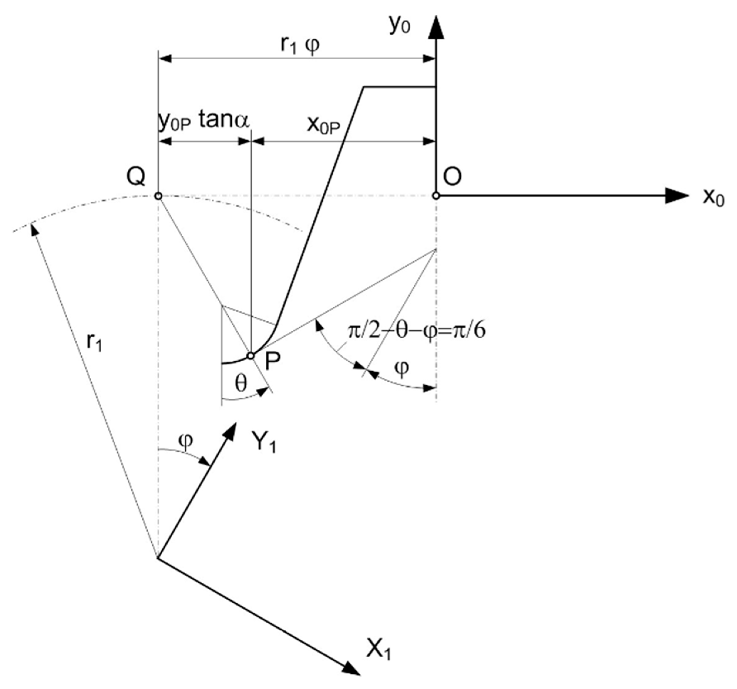
The determination of the bending arm can be written based on the spatial geometric conditions that can be interpreted in
Figure 3.
Location of the critical cross-section at the root:
where
is the central angle of the instantaneous position of point P measured from the centre of the corner radius of the base profile.
Width of the critical cross-section:
The distance of the critical cross-section from the pitch circle:
Using the above, the bending arm can be determined as follows:
The coordinates of the critical cross section must also be known on the base profile. The determination this can be done with the help of
Figure 4, as follows:
where
is the dedendum,
is the radius of the root,
is the module,
is the tooth clearance
. It can be seen from equation (15) that
is transcendental to
, therefore some numerical method must be used to determine the solution. The solution of equation (15) will provides the angle value where the value of the angle
is exactly equal to 30
0. Because the 30
0 straight line tangents the root curve at this point, which is the location of the critical cross-section in terms of bending stress.
4. Results
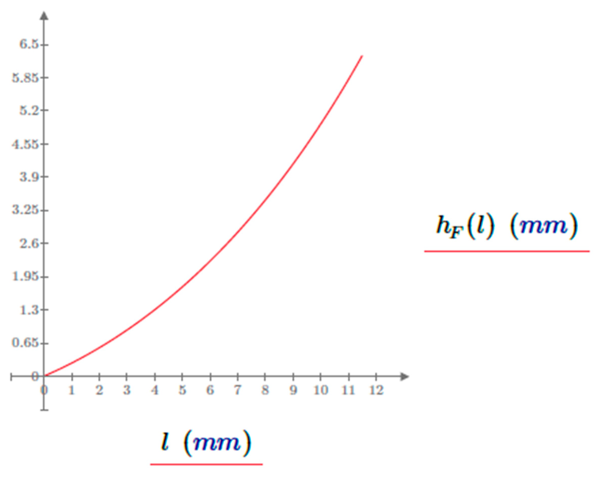
If the length of the bending arm (
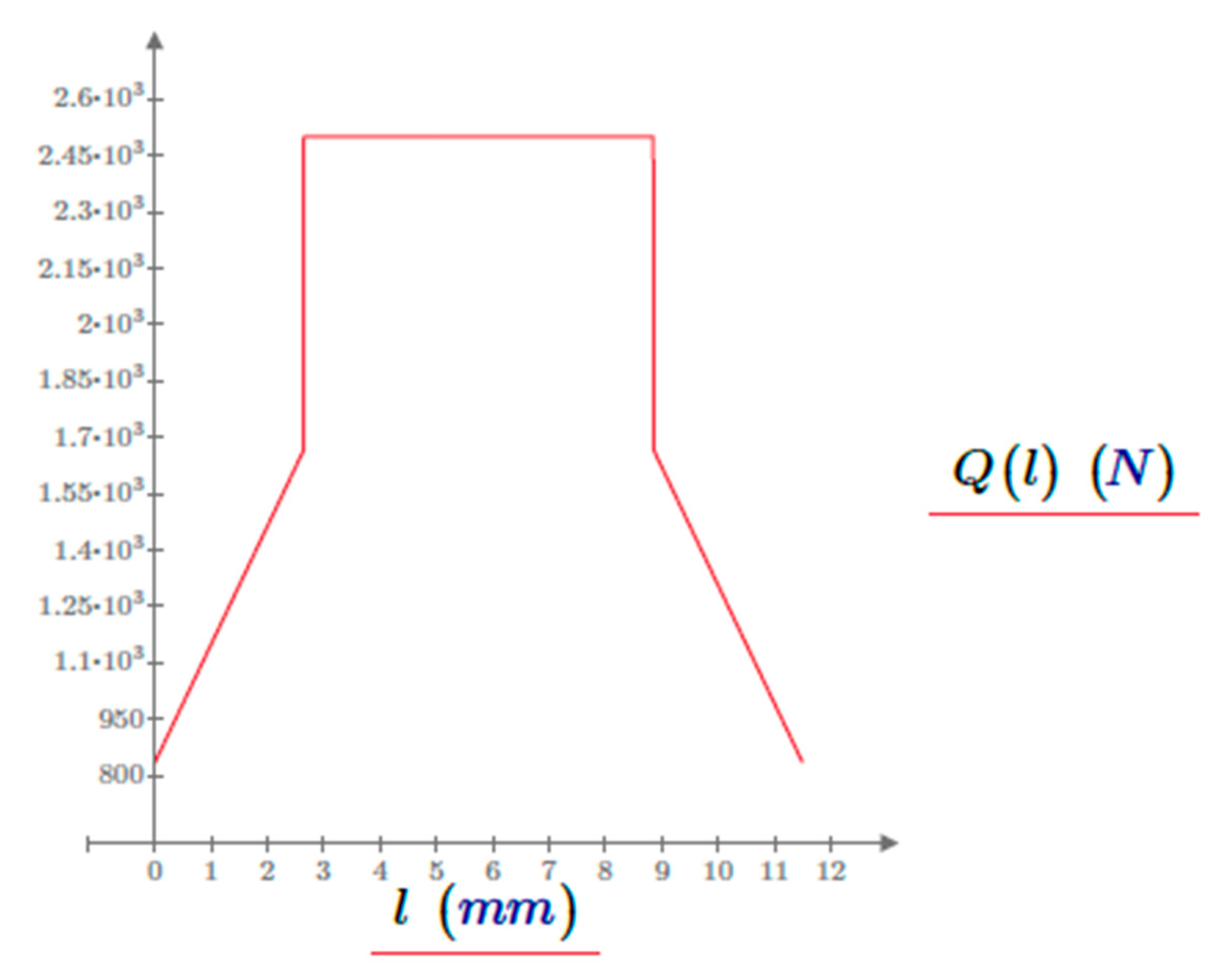
Figure 5) and the change in load (
Figure 6) along the path of contact are described at the
value, then using the sample example data, the following functions will be the results
Figure 7 shows the change in the bending stress along the path of contact with the data of the sample gear pair.
From
Figure 7, it is clear that the highest value of the bending stress that develops is located at the limit point of the section of connection stage of a pair of teeth, this is the limit point D of the exit from the section of connection stage of a pair of teeth, calculated with the data of the sample gear pair. However, the location of the highest possible values is also influenced by the geometrical conditions, so the determination of which point of path of contact is dangerous in terms of blending stress in the case of a specific gear can only be decided on the basis of an examination covering the entire length of the path of contact.
The bending stress that develops in the path of contact is influenced by the profile shift coefficients in their addendum circle radii and . Accordingly, their effect is valid in the quantities , and in relation (1), because the change of the profile shift coefficients causes the AE section of path of contact to shift along the path of contact, which affects both the load distribution and the geometric position of the load.
After performing the test described above for each value of , the set of objective function is obtained, from which each value can be assigned the extreme value, in this case the maximum, of the corresponding criterion function . The minimum of these maxima will provide the optimal solution according to the sought criterion, in our case the bending stress.
5. Conclusions
In the case of processes that extend in space and time, it is more correct and more favorable to carry out tests that cover the entire process, instead of comparing characteristics at arbitrarily chosen points.
By applying the proposed new method, potential tooth damage can be predicted already at the planning stage.
The new process can also be extended to helical and bevel gear types.
Funding
This research received no external funding.
Institutional Review Board Statement
Not applicable.
Informed Consent Statement
Not applicable.
Acknowledgments
Special thanks to András Eleöd, University of Budapest, and József Szente, University of Miskolc, retired university professors for their support providing ideas, encouragement and advise.
Conflicts of Interest
The authors declare no conflict of interest.
References
- Niemann, G. Maschinenelemente, B., II. ed.; Springer Verlag.; Berlin/Heidelberg, Germany, 1965.
- Diker, J. I. Evolventnije zaceplenyije sz uprjamimi zubcami. Organmetal. 1935. (In Russian). Available online: https://scholar.google.com/scholar_lookup?title=Evolventnije+zaceplenyije+sz+uprjamimi+zubcami&author=Diker,+J.I.&publication_year=1935&journal=Organmetal.
- Abderazek, H.; Ferhat, D.; Atamasovska, I.; Boualem, K. A differential evolution algorithm for tooth profile optimization with respect to balancing specific sliding coefficients of involute cylindrical and helical gears. Adv. Mech. Eng. 2015, 7, 1–11. [Google Scholar] [CrossRef]
- Almen, J. O. Surface Deterioration of Gear Teeth. Mechanical Wear, 1950, Cleveland, OH, USA, 229-288. Available online: https://cir.nii.ac.jp/crid/1572824499452760448.
- Tomori, Z. An Optimal Choice of Profile Shift Coefficients for Spur Gears. Machines, 2021, 9(6), 106. [CrossRef]
- Balajti, Z.; Ábel, J. Edge geometry test method with correctly positioned CCD cameras for production geometrical development of a worm gear hob with arched profile, Procedia Manufacturing, 2020, 51, 365-372. [CrossRef]
- Ábel, J.; Balajti, Z. Examination of Tool Wear of Teeth with Descriptive Geometry, XXVI. International Conference on Mechanical Engineering OGÉT 2018, Targu Mures, Romania, 26-29 April 2018, ISSN 2068-1267, 12-15. (In Hungarian). Available online: https://www.researchgate.net/publication/376186173_OGET_2018_EXAMlNATlON_OF_TOOL_WEAR_OF_TEETH_WlTH_THE_METHOD_OF_THE_DESCIPTIVE_GEOMETRY.
- Balajti, Z.; Dudás, I. The Monge Theorem and Its Application in Engineering Practice. Int. J. Adv. Manuf. Technol. 2017, 91, 739–749. [Google Scholar] [CrossRef]
- Ábel, J.; Balajti, Z. New aspects for post-sharpening adjustment of a cylindrical worm gear hob, XXIX. International Conference on Mechanical Engineering OGÉT 2021, Székelyudvarhely (Odorheiu Secuiesc), Romania, 25 April 2021, ISSN 2068-1267, 175-178. (In Hungarian). Available online: https://ojs.emt.ro/oget/article/view/499.
- Balajti, Z.; Ábel, J.; Dudás, I. Examination for post-sharpening adjustment of cutting edge of a worm gear hob with circle arched profile in axial section. Procedia Manuf. 2021, 55, 260–265. Available online: https://www.sciencedirect.com/science/article/pii/S2351978921002341?via%3Dihub. [CrossRef]
- Dudás, I.; Balajti, Z. Analysis of Bearing Pattern with New Mathematical Model, In proceeding of 13th International Scientific Conference, Cluj, Romania, 14-15, march, 2008, 73-76. (In Hungarian). Available online: http://real.mtak.hu/46084/.
- Dudás, I.; Balajti, Z. Modelling and development for describing bearing pattern of spiroid drives. Proceedings of the Sixth IASTED International Conference on” Robotics and Applications, Cambridge, USA, Oct. 31. – Nov. 02. 2005., 203-208, ISBN 0-88986-521-3. Available online: https://www.actapress.com/Abstract.aspx?paperId=22994.
- Balajti, Z. Examination and adjustment of bearing pattern in case of helicoid drives. Procedia CIRP 2018, 77, 267–270. [Google Scholar] [CrossRef]
- Dudás, I.; Bodzás, S.; Balajti, Z. Geometric analysis and computer aided design of cylindrical worm gear drive having arched profile. International Journal of Innovative Research in Engineering and Management (IJIREM), 2015, 2, 5, 10-14. ISSN: 2347-5552. Available online: https://www.ijirem.org/view_abstract.php?year=&vol=2&primary=QVJULTQ3.
- Ábel, J. Determination of Worm Gear Tooth Surface with Own Developed Computer Program. Multidisciplinary Sciences, 2021, 11, 4, 301-308. [CrossRef]
- Dudás, I.; Balajti, Z.; Bányai, K. Accurate Production of Helicoid Surfaces, III. International Congress of Precision Machining Vienna-Austria (ICPM 2005), 18-19. October 2005, 27-32. Available online: https://www.researchgate.net/publication/376186324_EXACT_PRODUCTION_OF_HELICOID_SURFACES.
- Varga, G.; Balajti, Z.; Dudás, I. Advantages of CCD Camera Measurements for Profile and Wear of Cutting Tools. Journal of Physics Institute of Physics Publishing in London, 2005, Conference Series 13, 159-162. [CrossRef]
- Dudás, I.; Balajti, Z. Analysis of Characteristic Curve in Case of the Wearing of the Grinding Wheel, In proceeding of microCAD 2009 International Scientific Conference, Section M: Production Engineering and Manufacturing Systems, Miskolc, Hungary, 19-20 March 2009, 269-276, ISBN 978-963-661-866-7 Ö, 978-963-661-877-0. Available online: https://www.researchgate.net/publication/375923591_ANALYSE_OF_CHARACTERISTIC_CURVE_IN_CASE_OF_THE_WEARING_OF_THE_GRINDING_WHEEL.
- Dudás, I.; Leirath, F.; Balajti, Z. Analysis of the Production Process of the Arched Worm Profile, In proceeding of 12th International Conference on Tools, Miskolc, Hungary, 6-8. September 2007. 169-174. Available online: https://www.researchgate.net/publication/376186327_Analaysis_of_the_Production_Process_of_the_Arched_worm_profile_In_Proceeding_of_12th_INTERNATIONAL_CONFERENCE_on_TOOLS_2007_Miskolc_Hungary.
- Mándy, Z.; Dudás, I.; Balajti, Z. Solving the Pitch Fluctuation Problem Using Affinity in Case of Manufacturing of the Conical Screw Surface with Apex Setting, In proceeding of 27th International Conference on Mechanical Engineering, ISSN 2068-1267 2668-9685, Oradea, Romania, 2019, 336-339. (In Hungarian). Available online: https://www.researchgate.net/publication/375923591_ANALYSE_OF_CHARACTERISTIC_CURVE_IN_CASE_OF_THE_WEARING_OF_THE_GRINDING_WHEEL.
- Dudás, I.; Balajti, Z. Analyzing of Helicoid Surfaces Having the Same Axis by Mathematical Model, In Proceeding of 10th International Research/Expert Conference „Trends in the Development of Machinery and Associated Technology” TMT 2006, Barcelona-Lloret de Mar, Spain, 11-15 September, 2006, ISBN 978-9958-617-28-5. Available online: https://www.tmt.unze.ba/proceedings2006.php.
- Balajti, Z.; Mándy, Z. Proposed solution to eliminate pitch fluctuation in case of conical screw surface machining by apex adjustment. Procedia Manufacturing, 2021, 2351-9789, 55, 266-273. Available online: https://www.sciencedirect.com/journal/procedia-manufacturing/vol/55/suppl/C.
- Hofer, H. Die Reibungs- und Abnützungverhaltnisse an Evolventenverzahnungen Mitt. d. Bodensee Bezirkvereins, 1922, 1, 1-5. (In German).
|
Disclaimer/Publisher’s Note: The statements, opinions and data contained in all publications are solely those of the individual author(s) and contributor(s) and not of MDPI and/or the editor(s). MDPI and/or the editor(s) disclaim responsibility for any injury to people or property resulting from any ideas, methods, instructions or products referred to in the content. |
© 2023 by the authors. Licensee MDPI, Basel, Switzerland. This article is an open access article distributed under the terms and conditions of the Creative Commons Attribution (CC BY) license (http://creativecommons.org/licenses/by/4.0/).
