1. Introduction
Direction of arrival (DOA) estimation using array processing has focused much attention in these years and has been widely applied in many fields, such as wireless communication, radar, sonar, medicine and other engineering applications [
1,
2,
3,
4,
5,
6,
7,
8,
9]. In the past decades, numerous subspace based DOA estimation algorithms, e.g., multiple signals classification (MUSIC) [
10,
11,
12,
13,
14,
15,
16,
17] and estimation of signal parameters via rotational invariance techniques (ESPRIT) [
18,
19,
20,
21,
22], have been proposed for uniform linear arrays (ULA) [
23,
24] and attracted much attention due to their high resolution and performance. However, the adjacent antenna element spacing is required to be less than half wavelength so that the phase ambiguity problem [
25] is avoided. But it limits the array aperture and consequently influences the mutual coupling [
26] between the elements and the estimation performance. Therefore, a non-uniform linear array has been recently proposed to increase the degrees of freedom (DOF) of the array, known as a sparse array. The sparse array breaks the limit of half wavelength. Coprime arrays [
27,
28] have aroused wide attention due to the improvement of DOA estimation performance. Meanwhile, due to the larger array aperture, less mutual coupling effect arises. A coprime linear array (CLA) consists of two ULAs with the inter element spacing larger than half-wavelength, so a higher resolution, larger array aperture and less mutual coupling effect can be attained [
29,
30]. Recently, the coprime arrays have been thoroughly investigated. A subarray-based method to solve the ambiguity problem is proposed in [
31]. The algorithm considers the total array as two subarrays and processes the two subarrays separately. By combining the estimates and finding the nearest spectral peaks from MUSIC spectrums of two subarrays, the phase ambiguity problem can be eliminated. However, this method suffers the severe computational complexity due to the global angular searching. Concerning this, a partial spectral search method is proposed in [
32] to decrease the computational complexity, which employs the linear relationship among ambiguous DOA estimates and searches over a small sector. However, these mentioned methods estimate the DOAs by combing the results of the two subarrays of the CLA, so some problems result in:
(i)DOF is limited by the subarray which has the smaller number of elements; (ii)only self information of two subarrays is exploited but mutual information is wasted, as a result, DOA estimation performance is affected and optimal DOA estimates can not be achieved; (iii)these methods need further process to eliminate the ambiguous angles.
To solve these problem, an unfolded coprime linear array (UCLA) is proposed, which unfolds the two subarrays in two opposite directions so that the array aperture is extended [
33]. For the UCLA, the array is processed as one total array. In this way, both self information and mutual information is utilized. Ambiguity problem is suppressed by stacking the two directional matrices of two subarrays. Also, the method can achieve the full DOFs due to the employment of the whole array. Nevertheless, this technique is not always true. When the source signals satisfy some relations, the method will not work. In the case of three signals, for the two subarrays, when it exists two different signals having the same steering vectors as the given DOA, the phase ambiguity still exists. Aiming to tackle the problem, Yang et. al. proposed a beamforming based technique by defining a decision variable [
34] to eliminate the phase ambiguity. However, this method employs other technique to distinguish the real DOAs besides MUSIC spectral searching, which can increase the computational complexity. Meanwhile, this method does not always work and it usually depends on the decision variable. When the decision variable is small, phase ambiguity problem still occurs.
To solve the ambiguity problem, increase the detecting accuracy and decrease the computational complexity, we design to rearrange the position of the reference sensor so that the linear relation of the directional vectors is broken. Therefore, the MUSIC algorithm can be employed directly without ambiguous angles arising. Meanwhile, we can get the DOAs estimation and do not need any other technique to estimate. The method can achieve the full DOFs of the array. We compared the proposed method and the original methods and we notice that the proposed method can effectively tackle the phase ambiguity problem.
The paper is organized as follows: Section II introduces the array configuration and the data model of the received signals. Section III, we detailed derive the ambiguity problem and present the proposed method, and analyze the DOFs and Cramer-Rao Bound (CRB) of the proposed method. In Section IV, it shows extensive simulation results and demonstrates the superiority of the proposed algorithm. And finally, we give the conclusions in Section VI.
The main contribution of this paper can be concluded as follows.
(1)The proposed method can effectively eliminate the phase ambiguity problem by rearranging the reference element spacing and breaking the spectral function with the directional matrix.
(2)The designed array treats the array as a whole so that it can achieve the full DOFs hence improves estimation performance.
(3)CRB, as the lower bound for unbiased estimation, is provided as a standard to measure the estimation performance. And it is validated that the designed array can achieve the lower CRB.
(4)The designed array can achieve DOA estimation with an excellent DOA estimation performance and it does not need additional algorithms.
Notations: Throughout this paper, we use uppercase (lowercase) bold characters to denote matrices (vectors). , and represent the transpose, conjugate and transpose conjugate operators, respectively. And represents the expectation operator.
2. Array Signal Model
As depicted in
Figure 1, we consider an UCLA with
sensors. For the array, it is composed of two uniform linear subarrays. One subarray has
sensors and the other one has
sensors, respectively. And
and
are a pair of coprime integers. Meanwhile, it has
. It can be noticed that the two subarrays are overlapping at the position of
, so we can compute the total sensors of the array as
. In the
Figure 1, the inter element spacing of the subarray 1 can be denoted as
. And the inter element spacing of the subarray 2 can be denoted as
, where
and
means the wavelength.
Assume that there are
K narrowband sources impinging on the array which locates at
with signal powers
.
denotes the
k-th signal where
and
. Also, we suppose that these signals are far-field uncorrelated. The received signal at time
is denoted as [
10]
where . and are steering matrices of the two subarrays, respectively. and . is steering vector for the subarray 1, and is steering vector for the subarray 2, respectively. is the signal emitted by the -th target at time , where and means the sampling number. stands for the additive white Gaussian noise and obeys the normal distribution and is independent from source signals. is the noise vectors of subarray 1. And denotes the noise vectors of subarray 2.
3. Ambiguity Problem Demonstration and Resolution
This section introduces the cause of phase ambiguity problem and illustrates the existing methods. Then the proposed improved array is presented and the full DOFs are achieved.
Preview
Generally, to avoid ambiguity problem, the inter element spacing is usually set to be no larger than half-wavelength, however, in this way, the array aperture is restricted. Coprime array, which is made up of two uniform linear arrays and the inter element spacing is larger than half wavelength.
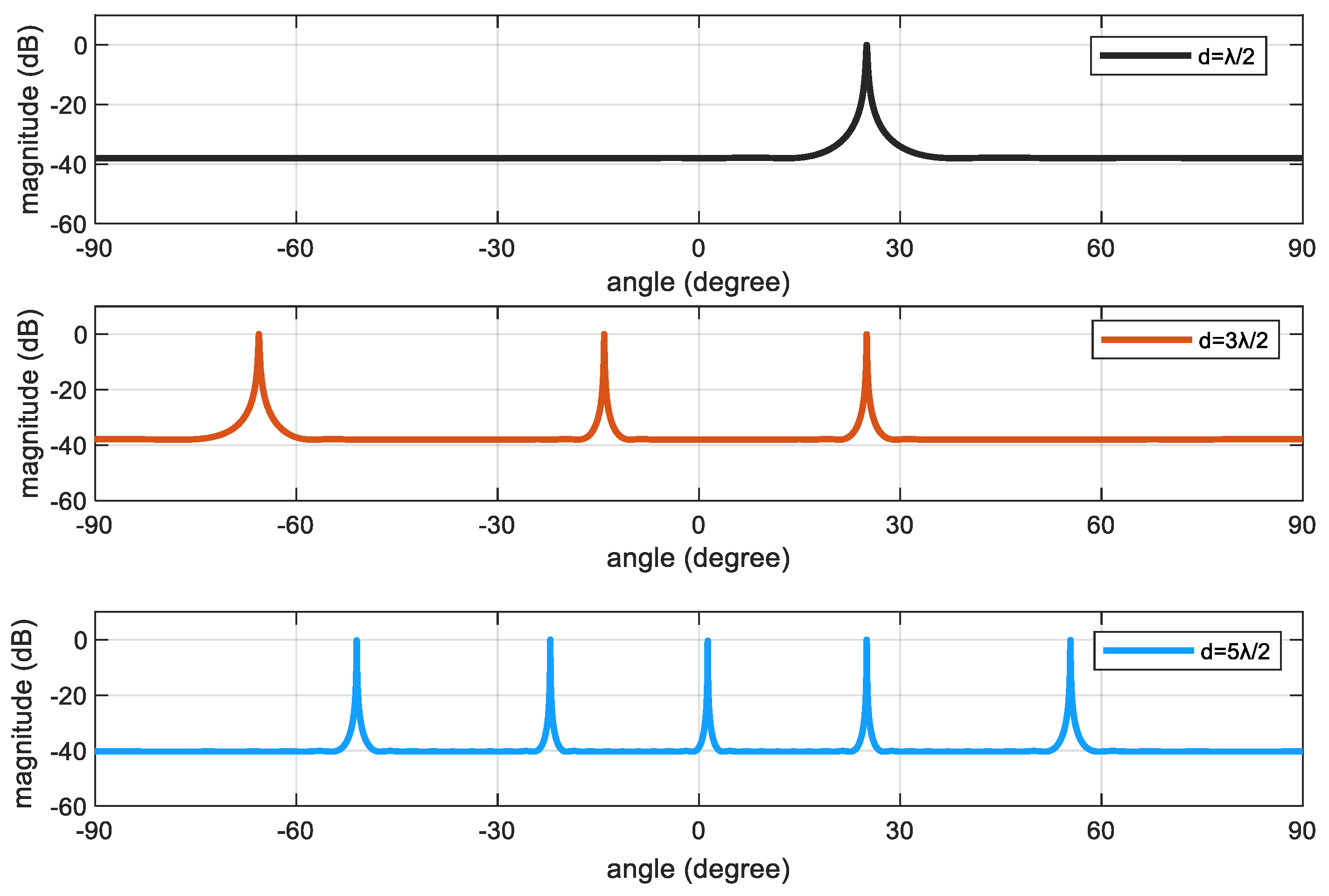
Figure 2 depicts the relationship between the element spacing and the number of DOA estimation. It considers that there is one signal coming from
. From the picture, we can get that when the element spacing is set to be
no ambiguous angle results in. And when
or
, the ambiguous angles result in.
Case 1
In the case 1, we consider that there are two signals coming from .
Assume that there are two signals
and
which are real angles. The corresponding directional vectors
and
can be attained. And we can get
Assume
and
are ambiguous angles of
and
.Therefore, corresponding steering vectors
and
can be attained. Then we can get
where and .
Due to the coprime property of and , the Eq. (9) is not satisfied. That is to say, in the case of two signals of and , phase ambiguity problem does not occur.
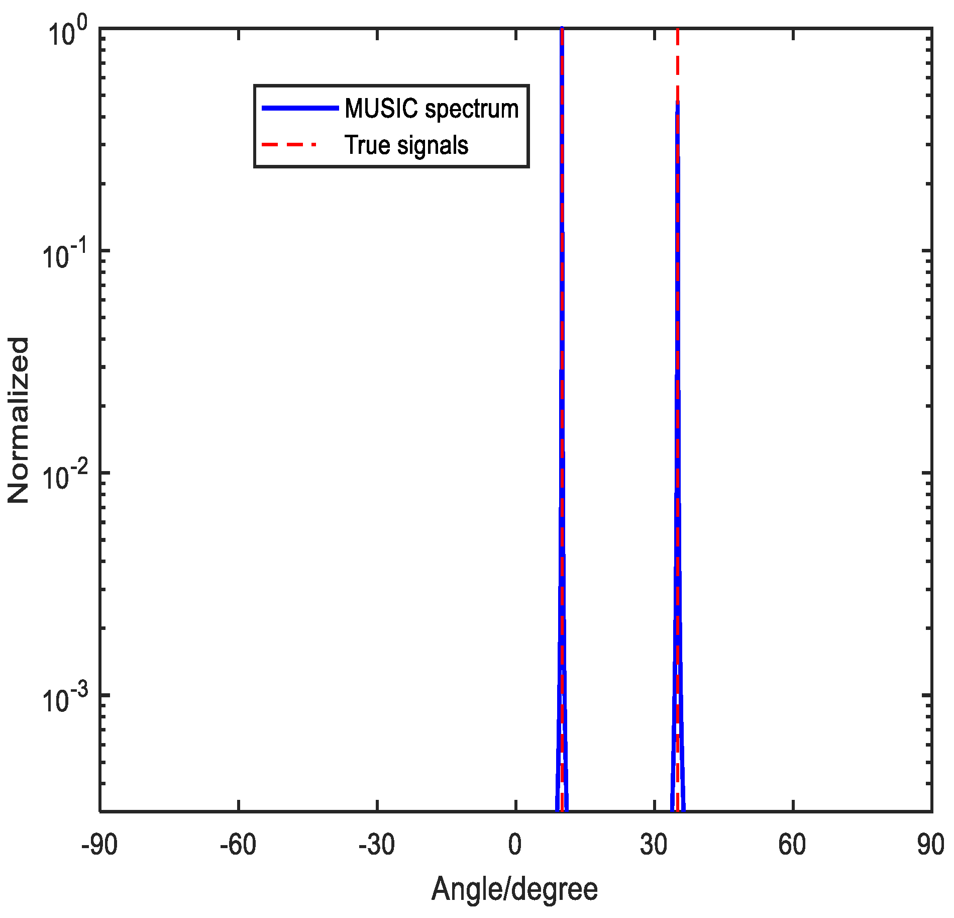
Figure 3 depicts spectrums without ambiguity by the method proposed in [
33]. The two signals are
. SNR and the snapshots are set to be
and
, respectively. We can draw a conclusion that the method proposed in [
33] can tackle the phase ambiguity problem with case 1.
Case 2
In the case 2, consider three signals with
. Similarly, we suppose
and
to be ambiguous angles of
and
, respectively. Corresponding directional vectors can be denoted as
and
. If the relationship that the sine function of the third signal
equals to
and
is satisfied, the phase ambiguity problem results in.
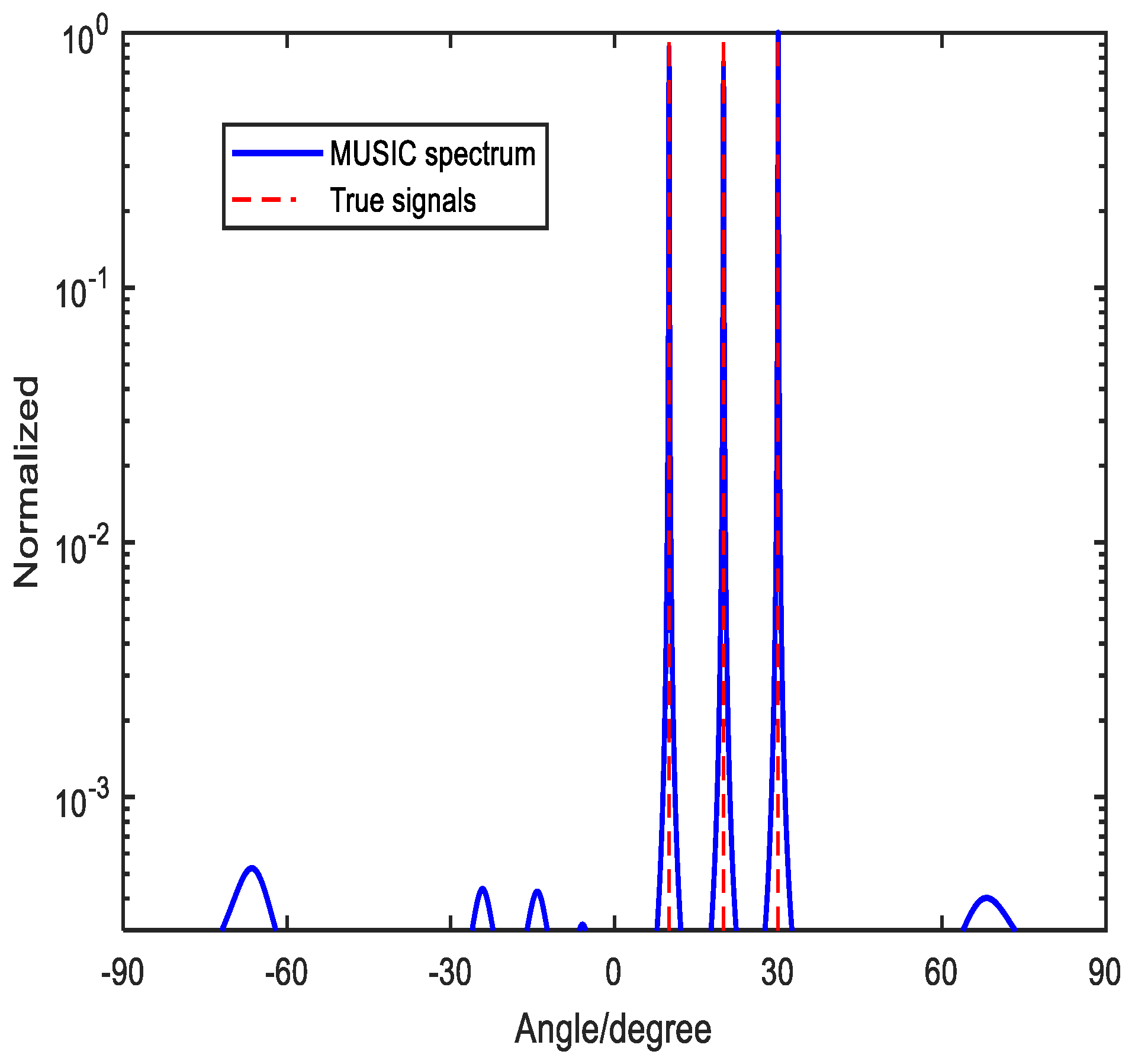
Figure 4 shows the spectrums of the method in [
33], where it has three target signals with
and
We set the number of snapshot to be
and
. It is depicted clearly in
Figure 3 that the method proposed in [
33] still has no difficulty to resolve the three source signals. However, this method is not always true. When these three source signals satisfy relationship that the sine function of third signal
equals to
and
, the method in [
33] will not work and we will illustrate in case 3.
Figure 3.
No ambiguous angle arises with 2 source signals, where
Figure 3.
No ambiguous angle arises with 2 source signals, where
Figure 4.
No ambiguous angle arises with the given 3 source signals, where
Figure 4.
No ambiguous angle arises with the given 3 source signals, where
Case 3
From the case 2, we notice that the method in [
33] can effectively detect three signals without the ambiguous angles, whereas it is not always working. Then we illustrate the case 3 in the following.
Consider three target signals impinging the array with . Similar to case 2, we suppose and to be ambiguous angles of and , respectively. Corresponding directional vectors can be denoted as and . When it satisfies that the sine function of the third signal equals to and , the ambiguous angle will arise. In other words, phase ambiguity problem results in, which is invalidated in the following.
Suppose that the third angle
whose corresponding sine function equals to
and
. It has
Then we can get the relationship which exists among
,
and
where and .
It is obvious that the forth angle arises. That is to say, phase ambiguity problem results in. Simulation is presented to demonstrate the analysis.
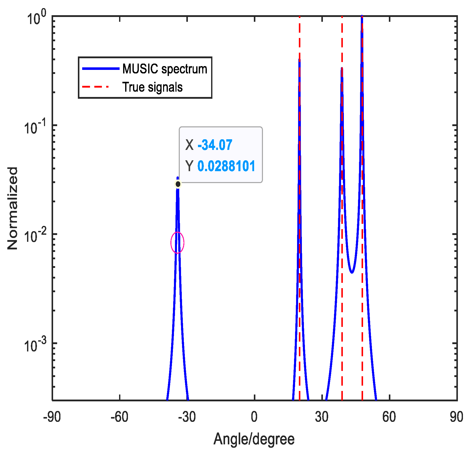
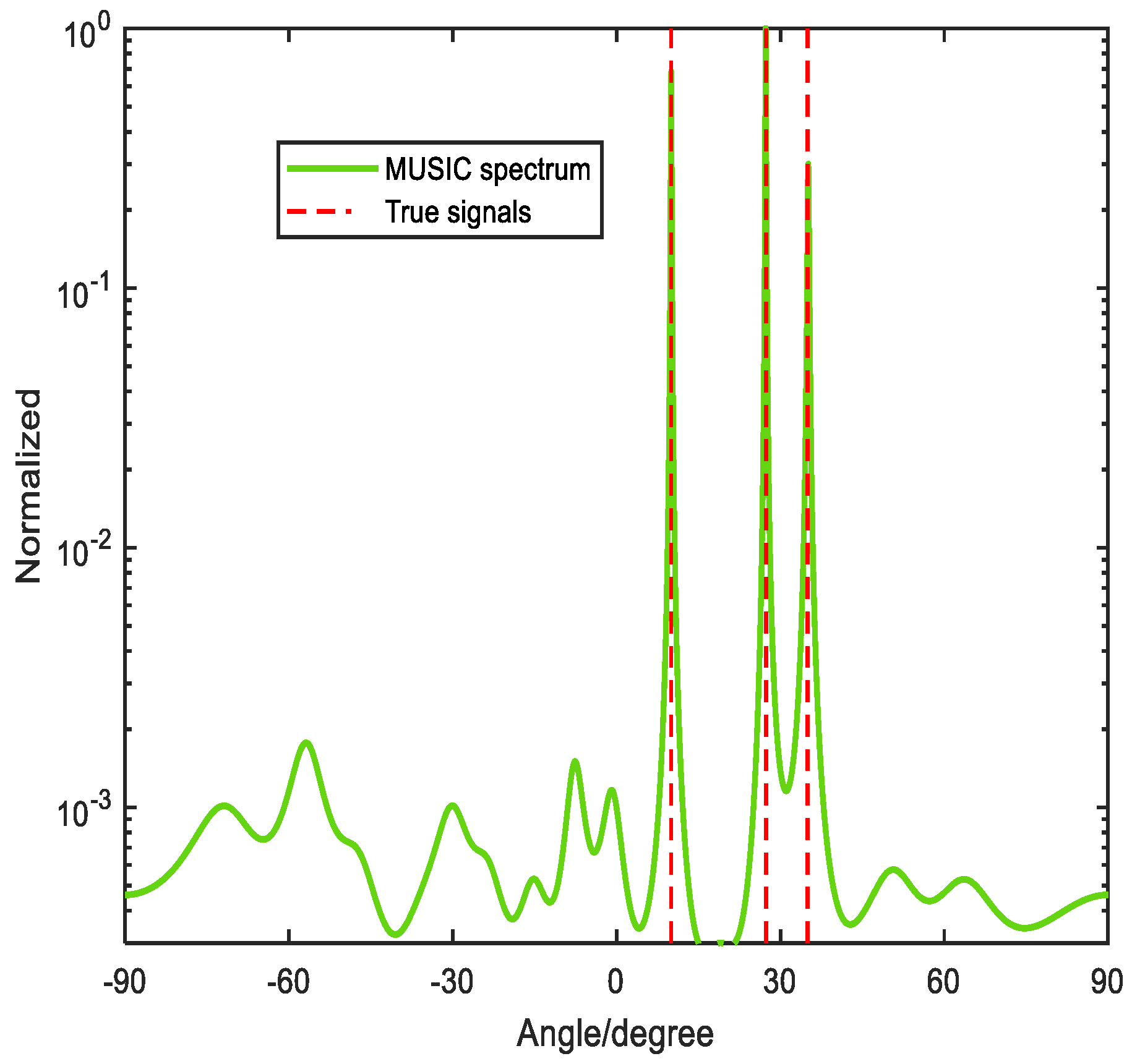
Figure 5 depicts the scenery that three signals
and
come to the array. The SNR and the number of the snapshots are set to be
and
, respectively. It can be found that these three signals satisfy
and
. And it is validated that the method in [
33] is not effective. From
Figure 5, we can notice that other than the three signals are detected while it exists the forth spectrum. Aiming at solving the ambiguity problem, Yang et. al. proposed a modified method by defining a decision variable[
34]. Meanwhile, the method combines the beamforming technique with MUSIC. However, this method is not always effective.
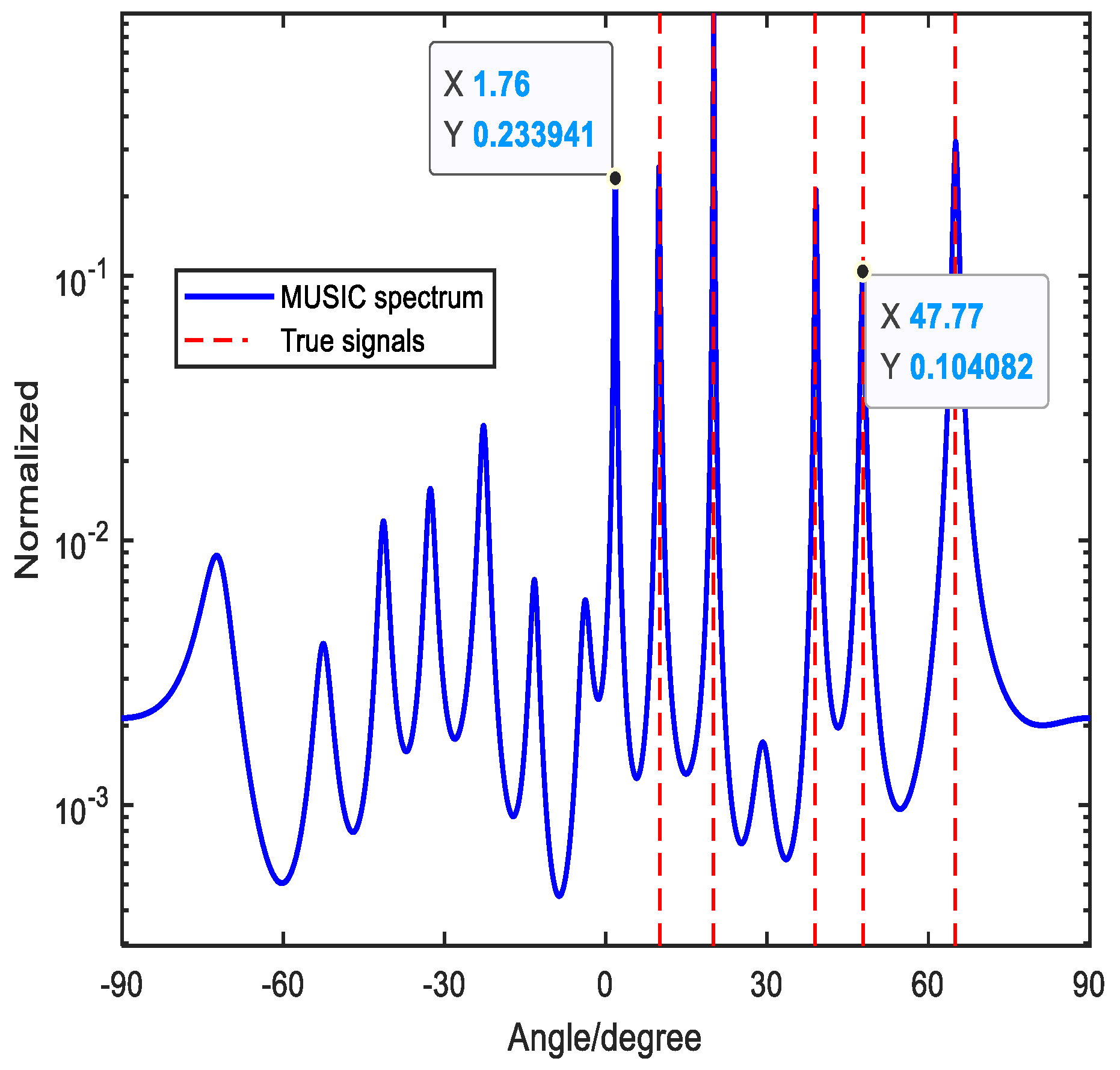
Figure 6 depicts that five signals come to the array. And by using the method in [
34], the five signals can be detected successfully, but it still has ambiguous angle, which can increase the ineffectiveness of the DOA estimation performance. To tackle this problem, we design an improved ambiguity–free array, where there are three coprime integers. By moving the reference element, the linear combination relation of the steering vectors can be broken. In this way, MUSIC algorithm can be applied directly and no additional algorithm needs. The method is illustrated in the following part.
4. Proposed Method for DOA Estimation
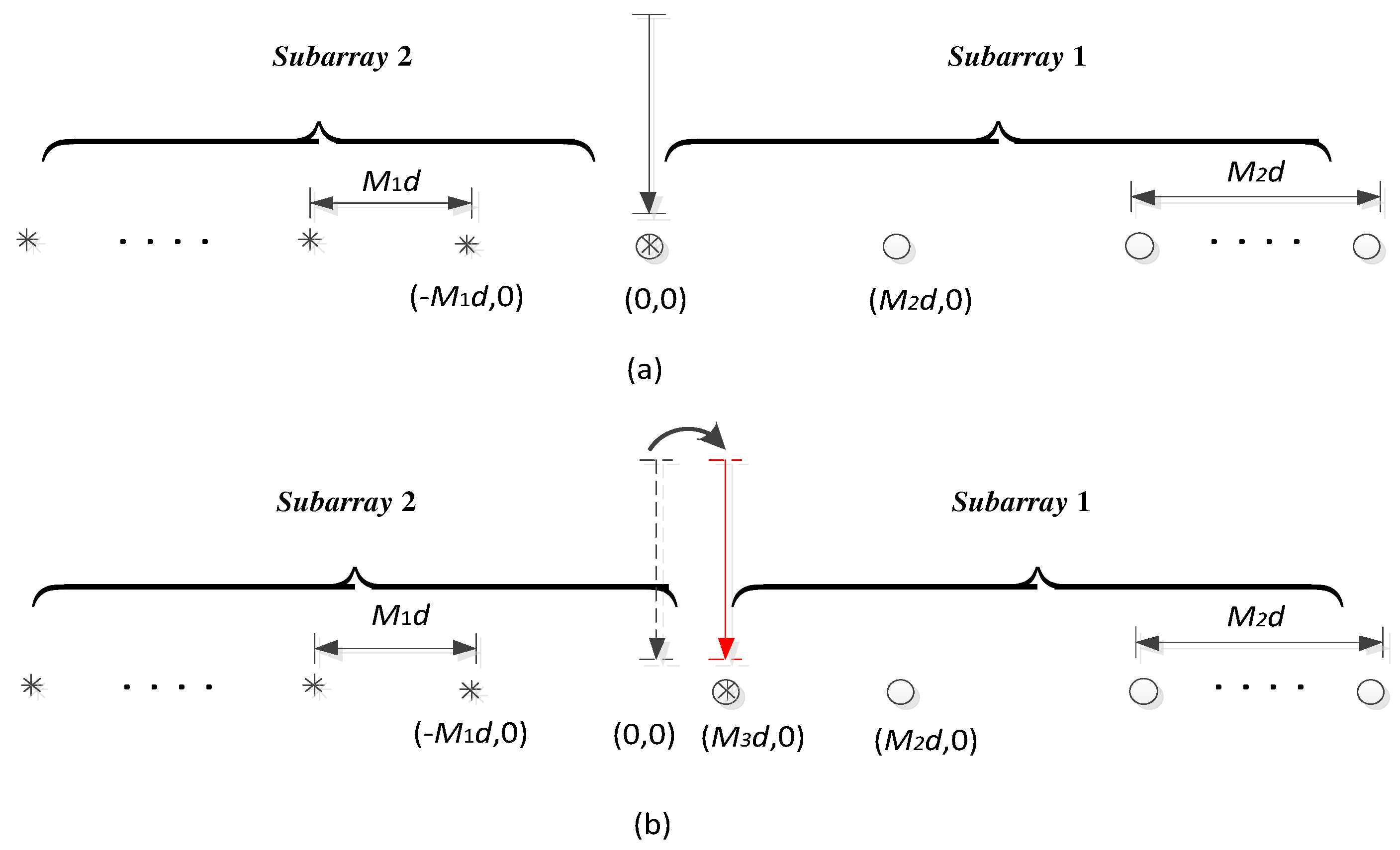
This section presents the proposed method to tackle the phase ambiguity problem with case 3. In the proposed method, we consider to rearrange reference sensor.
Figure 7(a) presents an UCLA, which is composed of two subarrays, including subarray 1 with
sensors and subarray 2 with
sensors.
Figure 7(b) presents a rearranged reference point instead of (0, 0). From the
Figure 7(b), for the new array, it still consists of two subarrays which contain
and
sensors, respectively. And position of the reference element is changed from (0, 0) to
, where
is the third coprime integer besides
and
. Due to the change of the reference sensor, it can be found that the steering vectors have changed correspondingly. In this way, two different directional vectors can be attained. By using this property, the resulted ambiguity can be broken.
In the rearranged array, denote the directional vectors of two subarrays with the
k-th signal as
So we can ger the steering vectors of source signal
denotes the directional vector of the total array .
Similar to Eq. (1), we can get the received signal
where . and are steering matrices of the two subarrays for IUCLA, respectively. and where and are denoted as Eq. (16) and Eq. (17). is the total array noise vector.
The corresponding total covariance matrix can be computed with
snapshots
The eigenvalue decomposition result of the total covariance matrix
can be denoted as
where and are the signal subspave and noise subspace matrix. And and include the eigenvalues.
Referring to the orthogonality between the signal subspace and the noise subspace, the spectral peak function of MUSIC can be denoted as [
10]
where .
Referring to the derivation above, when there are three sinals coming to the array and they satisfy and , phase ambiguity problem arises. In the following, we focus on proving and resolving the ambiguity problem.
Proof: Assume
.
and
represent the steering vectors of
and
with subarray 1, respectively. It has
where . So it exists .
Similarly, we can get that , where and represent the steering vectors of and with subarray 2, respectively. And we can get that spectral peak function is broken, in this way, we can get the accurate DOAs estimation without ambiguous angle , which means that the phase ambiguity problem is solved.
DOF Analysis
In this part, we will provide the DOF performance of the proposed method. The method can achieve the full DOFs. The
Figure 8 depicts there are three signals coming to the array with
. And the signals are
and
.
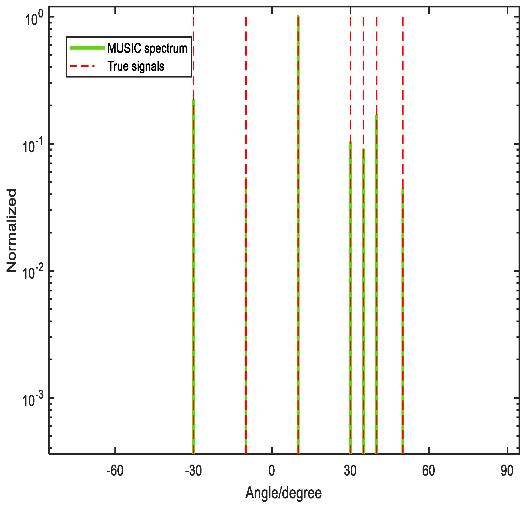
The
Figure 9 depicts there are seven signals coming to the array with
. And the signals are denoted as
and
. From the
Figure 8 and the
Figure 9, we can see the proposed method can achieve the full DOF.
Cramer-Rao Bound
The Cramer-Rao Bound (CRB), which is the lower bound for unbiased estimation, is provided as a standard to measure the estimation performance [
35,
36]. In this section, we derive the CRB of the designed IUCLA.
Construct the steering matrix of IUCLA as
where represents a sub-matrix containing the second row to the last one of since these two subarrays of IUCLA share the same element at the original point.
Referring to [
36], we can get the CRB as
where , and denotes the k-th column of .
5. Simulation Results And Discussion
In the simulation section, we validate the reliability of the proposed method compared with the methods in [
33] and [
34], where we employ an UCLA. And subarray 1 is with
sensors. And subarray 2 is with
sensors. Also, we present the computational complexity comparison of the methods mentioned above and CRB comparison of UCLA, CLA and the designed IUCLA.
A. Reliability Comparison
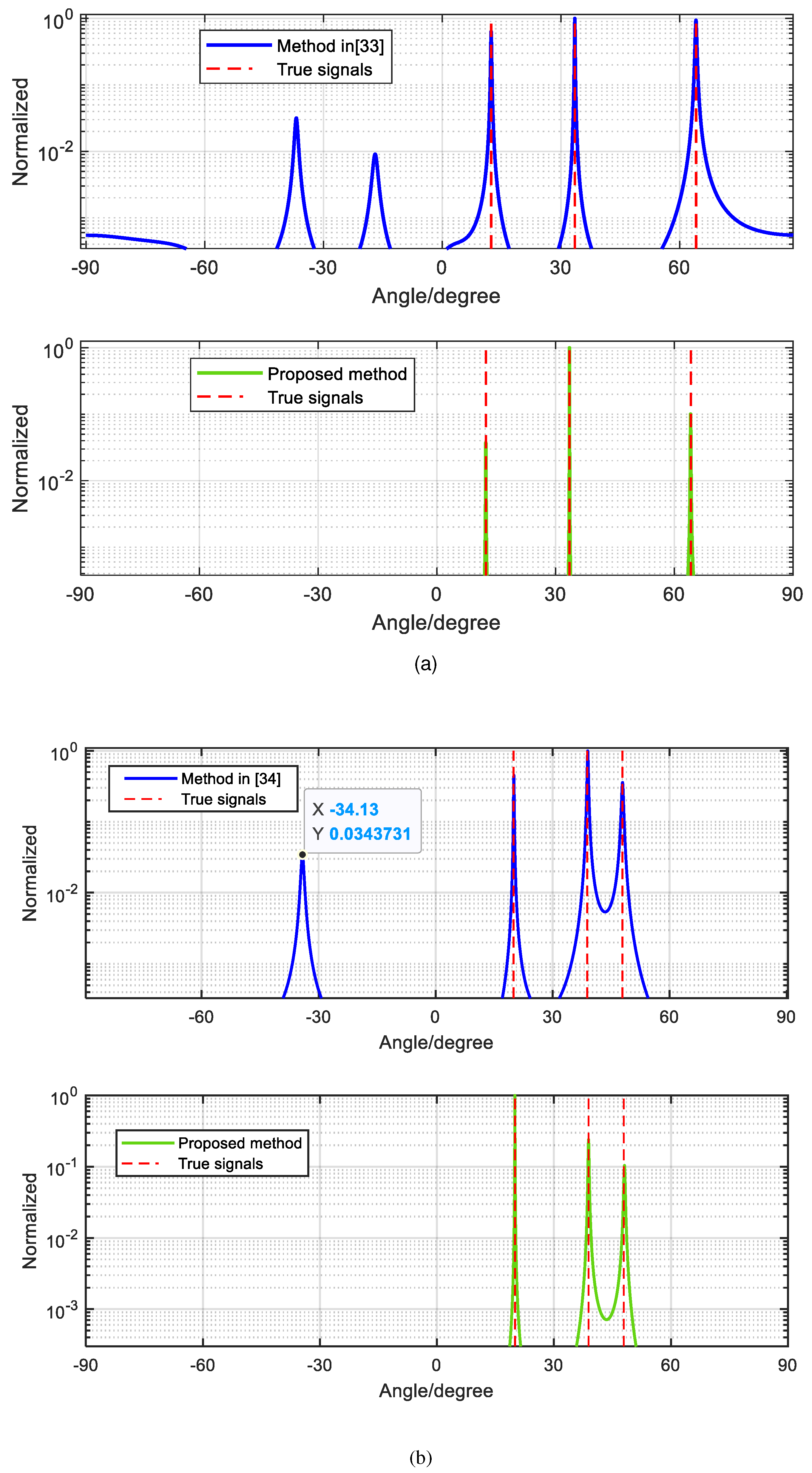
Example 1: Assume three signals
and
coming to the array. It can be noticed that these signals satisfy the Eq. (10). In the simulation, we set
and the number of snapshot
. We provide the simulation result of method in [
33] with the proposed method. From
Figure 10(a), we can see that using the designed method has no ambiguity when three sources satisfy the Eq. (10), whereas the ambiguity-free method still has ambiguity problem. It concludes that the proposed method can tackle the phase ambiguity problem of case2.
Example 2: Assume three signals
and
coming to the array. It can be noticed that these signals satisfy the Eq. (10). In the simulation, we set
and the number of snapshot
. We provide the simulation result of method in [
34] with the proposed method. From
Figure 10(b), we can see that method in [
34] is not that effective and the designed array using the spectral peak search algorithm has no ambiguity.
Estimation Properties Analysis
For the same simulation scenario mentioned above, we utilize the Root Mean Square Error (RMSE) to validate the estimation accuracy of the proposed method, which is defined as [37]
where
is the number of Monte Carlo simulations,
stands for the estimate of the
-th trial for the
-th theoretical angle
. And in this paper, we set
=1000.
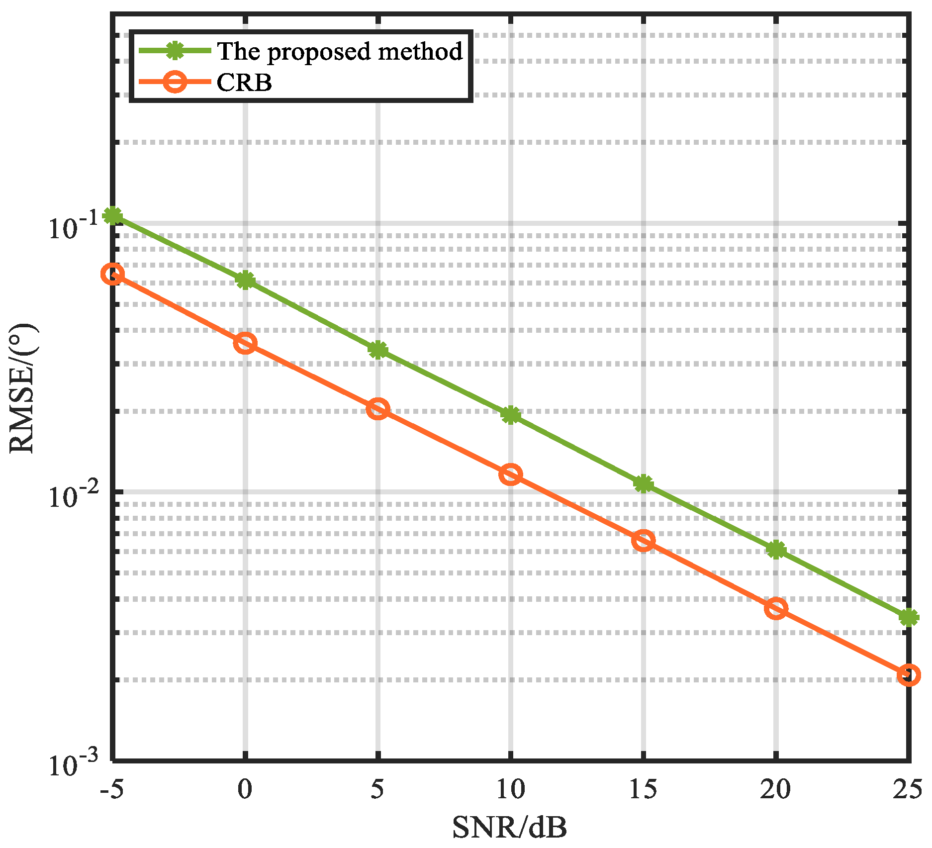
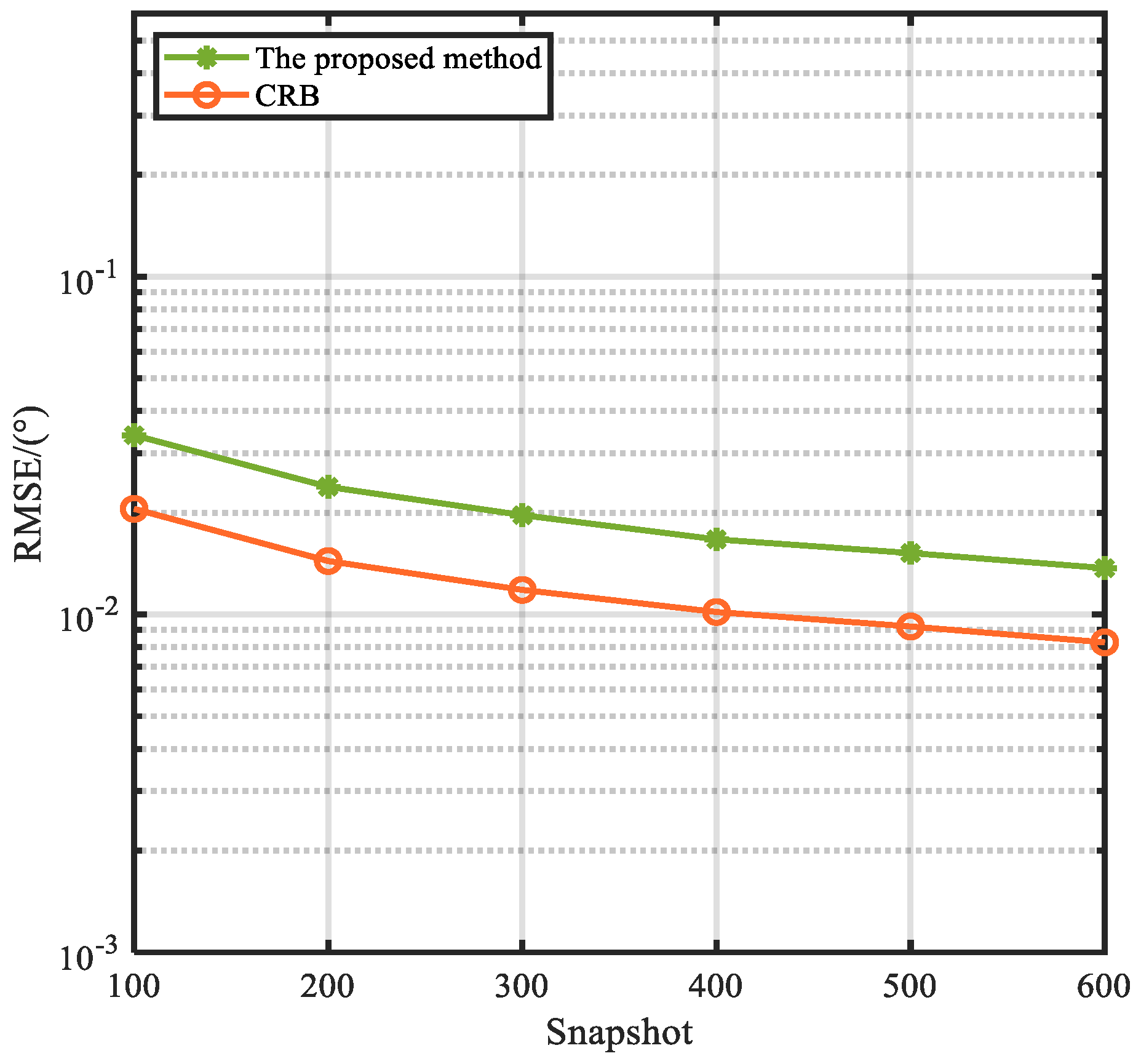
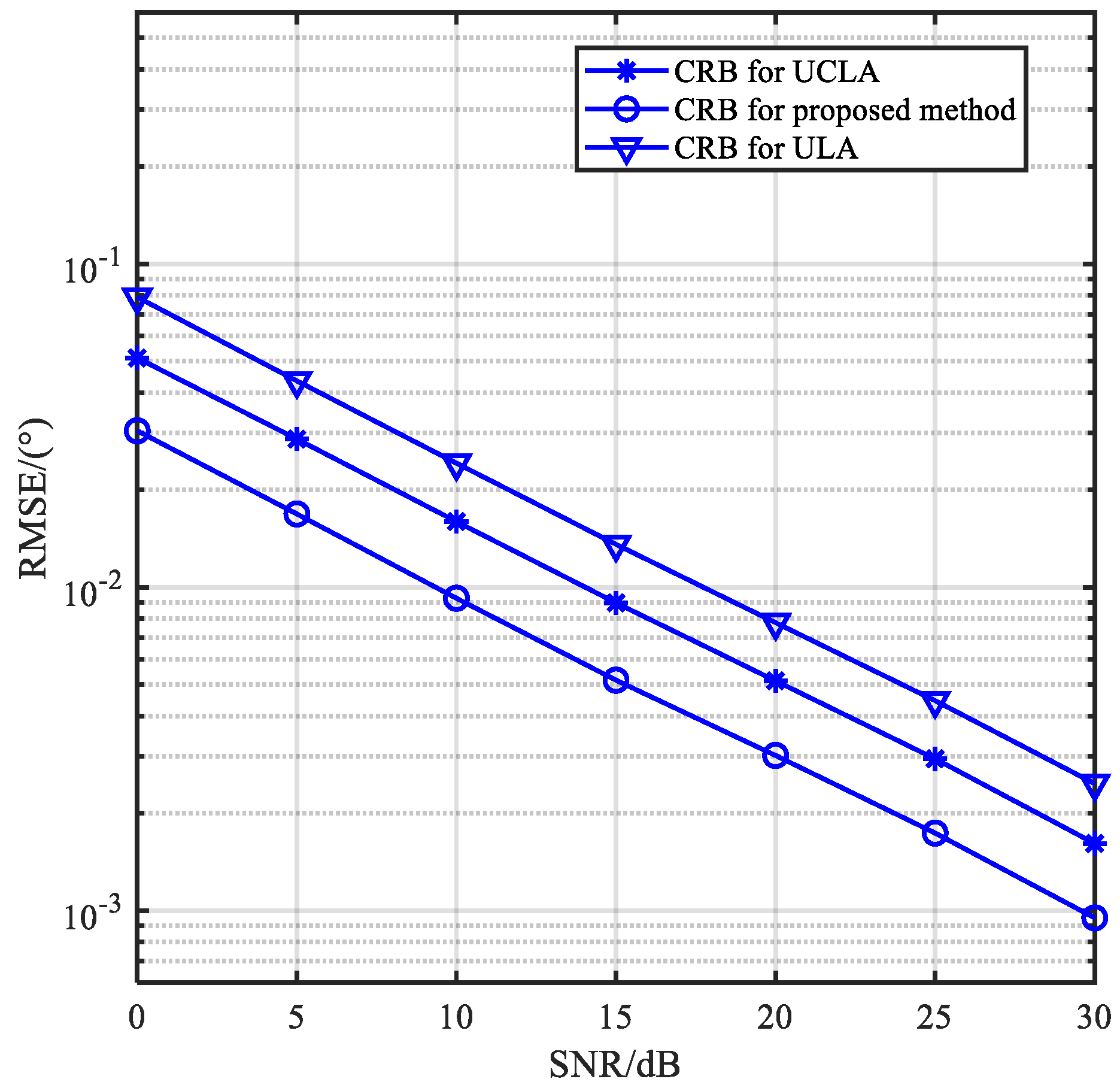
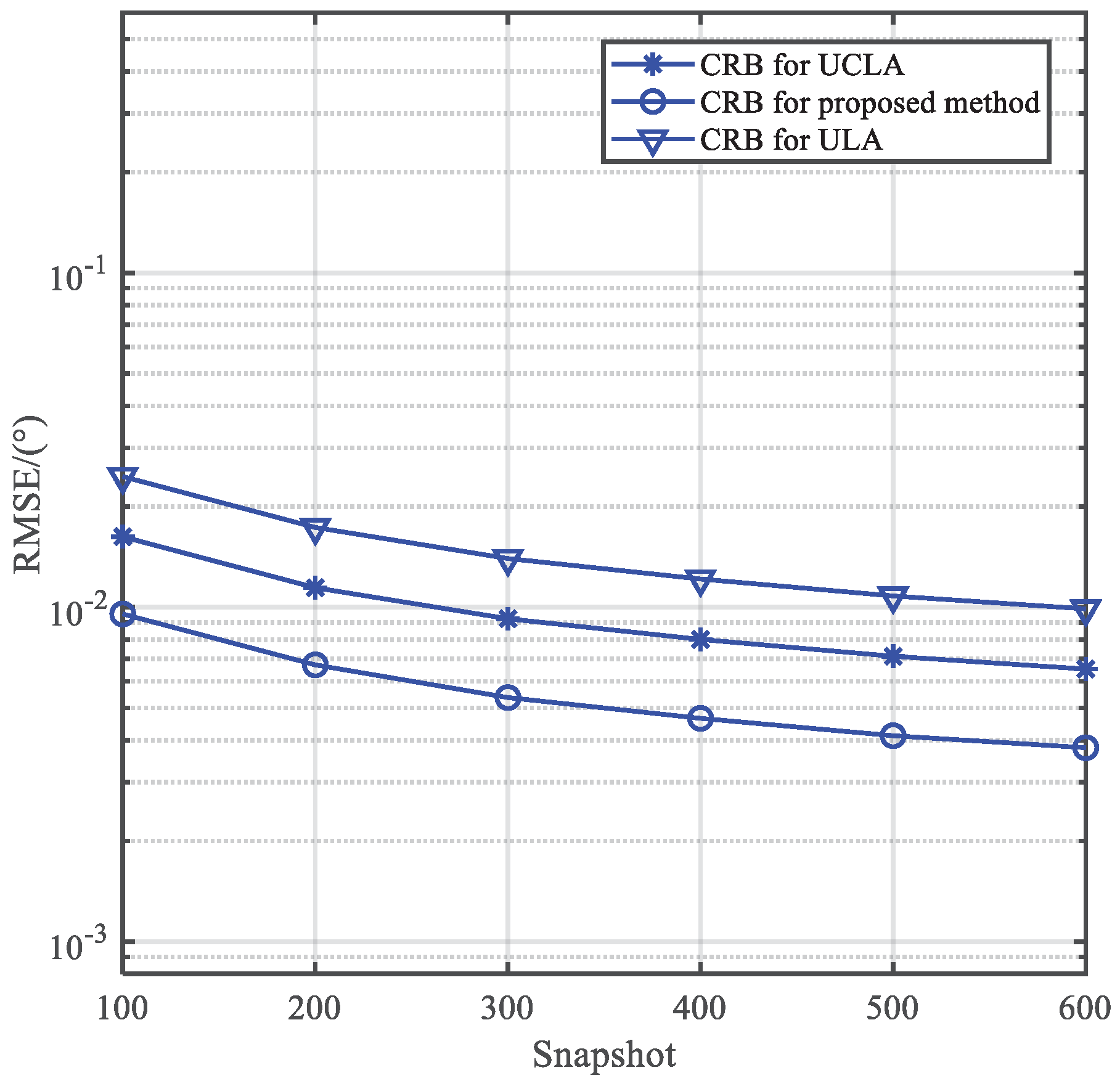
Figure 11 and
Figure 12 show the RMSE versus SNR and the number of snapshots, respectively. And the CRB is provided. It is observed that the estimaiton accuracy of the proposed method improves with the increase in SNR and the number of snapshots owing to its robustness against noise. And it is close to the CRB.
Computational Complexity Analysis
We compute the complexity of the proposed method. And compare the complexity with methods in [
33] and [
34]. The complexity of the propoded method is similar as the method in [
33], which is denoted as is
, where
. And
is the number of spectrum searching, where
is the searching step and we usually set
.
is the number of the snapshots. And the method in [
34] needs additional algorithm to distinguish the true DOAs besides MUSIC spectrum. So the complexity exceeds the method in [
33] and the proposed method, which is
.
is the number of searching of the additional beamforming technique.
Table 1 presents the computational complexity comparison and the running time of the methods above, which is computed by the MATLAB R2015b under the condition of Intel (R) Xeon (R) CPU E430 @3.10GHz and 8GB random access memory, where
which presents clearly that the proposed method is similar to the method in [
33], and outperforms the method in [
34].
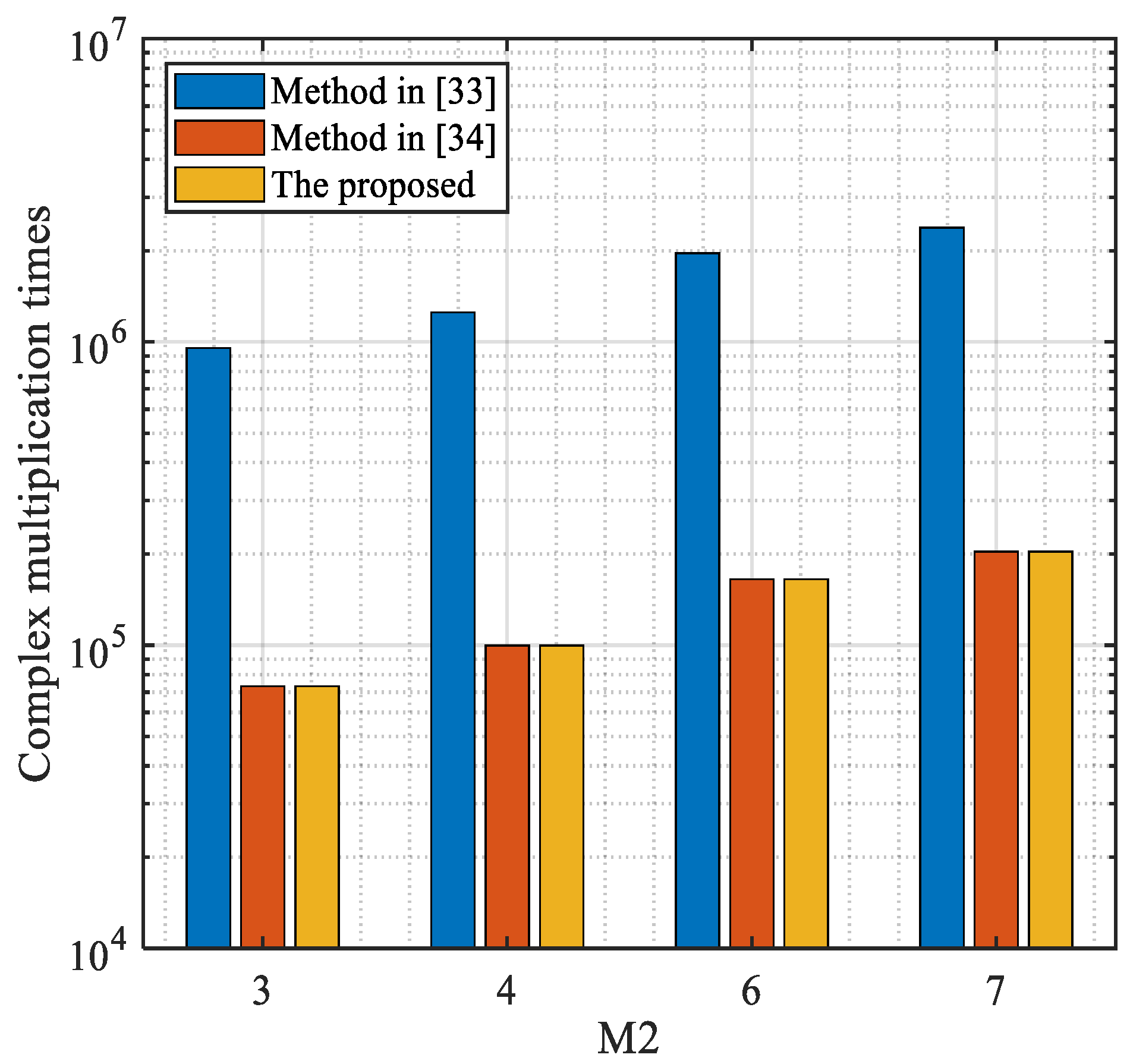
Figure 13 depicts the complexity comparison versus the number of the subarray 2, where the number of the subarray 1 is
. As the proposed method does not need additional procedure to identify the targets, it shows clearly that its complexity is much lower than the method in [
34] and near to the method in [
33].
CRB Analysis
We compare the estimation performance of the proposed method with IUCLA, UCLA and conventional ULA. In the simulation, for fair comparison, assume all arrays with the same number of sensors. We can conclude from
Figure 14 and
Figure 15 that the CRB and estimation performance of the proposed method with the 10 sensors is superior than the other two arrays.
6. Conclusions
Coprime array, due to its advantages, attracts much attention in recent years. Since the element spacing is larger than half wavelength, the phase ambiguity problem results in. An ambiguity-free method is proposed in [
33], which can tackle the ambiguity problem. In the case of two signals, this method can detect the targets effectively, neverthless, this method is not always true. In the case of three signals of which two signals have the same directional vector as the third DOA, ambiguous angle will arise. Aiming at resolving this problem, Yang. et. al proposed a modified method [
34] which defines a decision variable and combines the classic beamforming technique and MUSCI to eliminate the ambiguous angle. However, the accuracy of this method depends on the decision variable, and sometimes it is not true. Meanwhile, this method should need additional algorithm to detect the real DOAs other than MUSIC spectrum. So we design an improved ambiguity-free method by rearrangeing the reference sensor to change the relation of the directional vectors of subarrays. And MUSIC algorithm can be applied directly with no additional algorithm. Simulation results demonstrate that the proposed method can estimate DOAs effectively without ambiguous angles compared with the original methods.
Author Contributions
The main idea was proposed by Pan Gong and Xiaofei Zhang. Xiaofei Zhang conceived the experiments and provided many valuable suggestions. Pan Gong conducted experiments and collected data. Pan Gong wrote the manuscript and all the authors participated in amending the manuscript.
Acknowledgments
This work is supported by National Natural Science Foundation of China (No. 61371169, No.61601167, No.61601504, and No. 62004100), and Natural Science Research of Jiangsu Higher Education Institutions of China (No. 22KJD140004)and University level scientific research grant number (YK20-02-11, YK22-02-04).
Conflicts of Interest
The authors declare no conflict of interest.
References
- Gorcin A, Arslan H. A two-antenna single RF front-end DOA estimation system for wireless communications signals [J]. IEEE Transactions on Antennas and Propagation, 2014, 62(10): 5321-5333. [CrossRef]
- Krim H, Viberg M. Two decades of array signal processing research: the parametric approach [J]. IEEE signal processing magazine, 1996, 13(4): 67-94. [CrossRef]
- Chen P, Chen Z, Zheng B, et al. Efficient DOA estimation method for reconfigurable intelligent surfaces aided UAV swarm [J]. IEEE Transactions on Signal Processing, 2022, 70: 743-755. [CrossRef]
- Mei R, Tian Y, Huang Y, et al. 2D-DOA Estimation in Switching UCA Using Deep Learning-Based Covariance Matrix Completion [J]. Sensors, 2022, 22(10): 3754. [CrossRef]
- Zhao F, Hu G, Zhou H, et al. Research on Underdetermined DOA Estimation Method with Unknown Number of Sources Based on Improved CNN [J]. Sensors, 2023, 23(6): 3100. [CrossRef]
- Qiu S, Ma X, Zhang R, et al. A dual-resolution unitary ESPRIT method for DOA estimation based on sparse co-prime MIMO radar [J]. Signal Processing, 2023, 202: 108753. [CrossRef]
- Ma T, Du J, Shao H. A Nyström-Based Low-Complexity Algorithm with Improved Effective Array Aperture for Coherent DOA Estimation in Monostatic MIMO Radar [J]. Remote Sensing, 2022, 14(11): 2646. [CrossRef]
- Hamid U, Wyne S, Butt N R. Joint Model-Order and Robust DOA Estimation for Underwater Sensor Arrays [J]. Sensors, 2023, 23(12): 5731. [CrossRef]
- Wang X., Wang W., Li X., Liu J. Real-Valued Covariance Vector Sparsity-Inducing DOA Estimation for Monostatic MIMO Radar [J]. Sensors. 2015; 15: 28271–28286. [CrossRef]
- Schmidt R. Multiple Emitter Location and Signal Parameter Estimation [J]. IEEE Transactions on Antennas and Propagation, 1986, (34): 276-280. [CrossRef]
- Sun F, Gao B, Chen L, et al. A low-complexity ESPRIT-based DOA estimation method for co-prime linear arrays [J]. Sensors, 2016, 16(9):1367. [CrossRef]
- Wang Y Y, Chen J T, Fang W H. TST-MUSIC for joint DOA-delay estimation [J]. IEEE Transactions on Signal Processing, 2001, 49(4): 721-729. [CrossRef]
- Zhang Y, Ng B P. MUSIC-like DOA estimation without estimating the number of sources [J]. IEEE Transactions on Signal Processing, 2009, 58(3): 1668-1676. [CrossRef]
- Vallet P, Mestre X, Loubaton P. Performance analysis of an improved MUSIC DOA estimator [J]. IEEE Transactions on Signal Processing, 2015, 63(23): 6407-6422. [CrossRef]
- Merkofer J P, Revach G, Shlezinger N, et al. DA-MUSIC: Data-driven DOA estimation via deep augmented MUSIC algorithm [J]. IEEE Transactions on Vehicular Technology, 2023. [CrossRef]
- Lin J D, Fang W H, Wang Y Y, et al. FSF MUSIC for joint DOA and frequency estimation and its performance analysis [J]. IEEE Transactions on Signal Processing, 2006, 54(12): 4529-4542. [CrossRef]
- Qian C, Huang L, So H C. Improved unitary root-MUSIC for DOA estimation based on pseudo-noise resampling [J]. IEEE Signal Processing Letters, 2013, 21(2): 140-144. [CrossRef]
- Chen F J, Kwong S, Kok C W. ESPRIT-like two-dimensional DOA estimation for coherent signals [J]. IEEE Transactions on Aerospace and Electronic Systems, 2010, 46(3): 1477-1484. [CrossRef]
- Herzog A, Habets E A P. Eigenbeam-ESPRIT for DOA-vector estimation [J]. IEEE signal processing letters, 2019, 26(4): 572-576. [CrossRef]
- Lin J, Ma X, Yan S, et al. Time-frequency multi-invariance ESPRIT for DOA estimation [J]. IEEE Antennas and Wireless Propagation Letters, 2015, 15: 770-773. [CrossRef]
- Li J, Jiang D, Zhang X. DOA estimation based on combined unitary ESPRIT for coprime MIMO radar [J]. IEEE Communications Letters, 2016, 21(1): 96-99. [CrossRef]
- Wu N, Qu Z, Si W, et al. DOA and polarization estimation using an electromagnetic vector sensor uniform circular array based on the ESPRIT algorithm [J]. Sensors, 2016, 16(12): 2109. [CrossRef]
- Bai L, Peng C Y, Biswas S. Association of DOA estimation from two ULAs [J]. IEEE Transactions on Instrumentation and Measurement, 2008, 57(6): 1094-1101. [CrossRef]
- Wu J X, Wang T, Suo Z Y, et al. DOA estimation for ULA by spectral Capon rooting method [J]. Electronics Letters, 2009, 45(1): 1.
- Ballal T, Bleakley C J. Phase-difference ambiguity resolution for a single-frequency signal [J]. IEEE Signal Processing Letters, 2008, 15: 853-856. [CrossRef]
- Liao B, Zhang Z G, Chan S C. DOA estimation and tracking of ULAs with mutual coupling [J]. IEEE Transactions on Aerospace and Electronic Systems, 2012, 48(1): 891-905. [CrossRef]
- Pal P, Vaidyanathan P P. Nested arrays: A novel approach to array processing with enhanced degrees of freedom [J]. IEEE Transactions on Signal Processing, 2010, 58(8): 4167–4181. [CrossRef]
- Pal P, Vaidyanathan P P. Coprime sampling and the MUSIC algorithm [C]. IEEE Digital Signal Proc. Workshop and IEEE Signal Proc. Ed¬tion Workshop (DSP/SPE), 2011: 289-294. [CrossRef]
- Qin S, Zhang Y D, Amin M G. Generalized coprime array configurations for direction-of-arrival estimation [J]. IEEE Transactions on Signal Processing, 2015, 63(6): 1377-1390. [CrossRef]
- Raza A, Liu W, Shen Q. Thinned coprime array for second-order difference co-array generation with reduced mutual coupling [J]. IEEE Transactions on Signal Processing, 2019, 67(8): 2052-2065. [CrossRef]
- Zhou C, Shi Z, Gu Y, Shen X. DECOM: DOA estimation with combined MUSIC for coprime array [C]. IEEE International Conference on Wireless Communications and Signal Processing (WCSP), Oct. 2013:1–5. [CrossRef]
- Sun F, Lan P, Gao B. Partial spectral search-based DOA estimation method for co-prime linear arrays [J]. Electronics Letters, 2015, 51(24): 2053-2055. [CrossRef]
- Zheng W, Zhang X, Gong P, et al. DOA Estimation for Coprime Linear Arrays: An Ambiguity-Free Method Involving Full DOFs [J]. IEEE Communications Letters, 2017, 22(3): 562-565. [CrossRef]
- Yang X, Wang Y, Chargé P. Modified DOA estimation with an un¬folded co-prime linear array [J]. IEEE Communications Letters, 2019, 23(5): 859-862. [CrossRef]
- Stoica, P.; Nehorai, A. Performance study of conditional and unconditional direction-of-arrival estimation [J]. IEEE Trans. Acoust. Speech Signal Process. 1990, 38, 1783–1795. [CrossRef]
- Stoica, P.; Gershman, A.B. Maximum-likelihood DOA estimation by data-supported grid search [J]. IEEE Signal Process. Lett. 1999, 6, 273–275. [CrossRef]
|
Disclaimer/Publisher’s Note: The statements, opinions and data contained in all publications are solely those of the individual author(s) and contributor(s) and not of MDPI and/or the editor(s). MDPI and/or the editor(s) disclaim responsibility for any injury to people or property resulting from any ideas, methods, instructions or products referred to in the content. |
© 2023 by the authors. Licensee MDPI, Basel, Switzerland. This article is an open access article distributed under the terms and conditions of the Creative Commons Attribution (CC BY) license (http://creativecommons.org/licenses/by/4.0/).
