1. Introduction and Background
Shear behavior in structural components is complex and has been the subject of extensive research for decades – both for steel reinforcement [
1,
2,
3,
4,
5,
6,
7,
8,
9] or non-metallic reinforcement, such as carbon fiber reinforced polymer (CFRP) reinforcement [
10,
11,
12]. Despite numerous experimental investigations, there is still a lively discussion about the interplay of shear transfer actions, such as shear stresses of the uncracked compression zone, residual tensile stresses in the fracture process zone, aggregate interlock, dowel action, shear reinforcement (if existing) and direct strutting. While in principle there is consensus on the existence of these shear transfer actions, there is controversy about their contribution to the total shear capacity, the influence of various parameters on the shear transfer actions, and their interaction.
This lack of agreement results from the complexity of shear transfer actions and the variety of influencing parameter, e.g., from cross-sectional geometries, material properties, support and loading conditions. In addition, only in recent years novel measurement methods, such as digital image correlation (DIC), and measurement sensors, such as fiber optical sensors (FOS), have been used to a greater extent. The accuracy of the measurement of deformation and strain states could be highly enhanced and is not restricted to small areas, and as a result the detailed analysis of crack kinematics and investigations of the shear transfer actions are possible, e.g. [
8,
11,
13]. However, the exact procedure of measurement (e.g. definition of local coordinate systems, location of measured displacements, number of measurements) used to analyze crack kinematics with DIC also influences the results, which means that some of the results are maybe not directly comparable.
However, there is still a great need for further research, construction projects have already been implemented with project-related or national technical approvals [
15,
16,
17]. The future successful use of this composite material in practice depends mainly on the availability of design models [
12]. Currently, there is no existing standard for the design of concrete structures with non-metallic reinforcement in Germany, although a draft guideline has already been developed [
14]. The prerequisite for an economic design ensuring the efficient use of raw materials is a high prediction accuracy, coupled with an easy applicability of the design formulas for the structural engineer. In other countries, there are already existing standards for the design of structural CFRP reinforced members, e.g. [
18,
19,
20,
21]. In all design equations for shear capacity, the support and load conditions are insufficiently considered. However, it is already known from experiments on (steel) reinforced concrete members that, for example, members with distributed loading achieve higher shear capacities compared to members with single loads. The shear capacity of continuous systems is also greater than that of single-span members featuring the same span length (e.g. [
8,
22]). The previous investigations on shear behavior of concrete members reinforced with non-metallic reinforcement were primarily carried out on single-span beams with single loads. A recent comprehensive overview of the test data is given in [
11].
To contribute to the complete understanding of the shear transfer, further shear tests were carried out in the project C02* of the Collaborative Research Centre/Transregio 280 (CRC/TRR280). The aim of this CRC is to create new foundations for the construction of the future. Therefore, extensive investigations were carried out on structural elements primarily used in the construction industry. The test results described in this paper show the positive effect on the shear capacity of CFRP reinforced concrete members without shear reinforcement that are continuously supported and loaded by distributed loading compared to simply supported members with concentrated loads. A smaller study of four shear tests on members with shear reinforcement was performed to enhance the experimental investigations in project C02*, which is published in [
23].
2. Experimental Study
2.1. Experimental Concept and Test Program
For the experimental study sixteen CFRP reinforced concrete members without shear reinforcement were tested. In addition to the data on shear capacity as a function of support condition and loading type, the tests are intended to be used for future extensive investigations on the shear transfer and failure mechanisms. For this reason, state-of-the-art photogrammetric and optical measurement methods were also used in order to obtain detailed knowledge of the crack kinematics and the deformation and strain states of the component and the reinforcement.
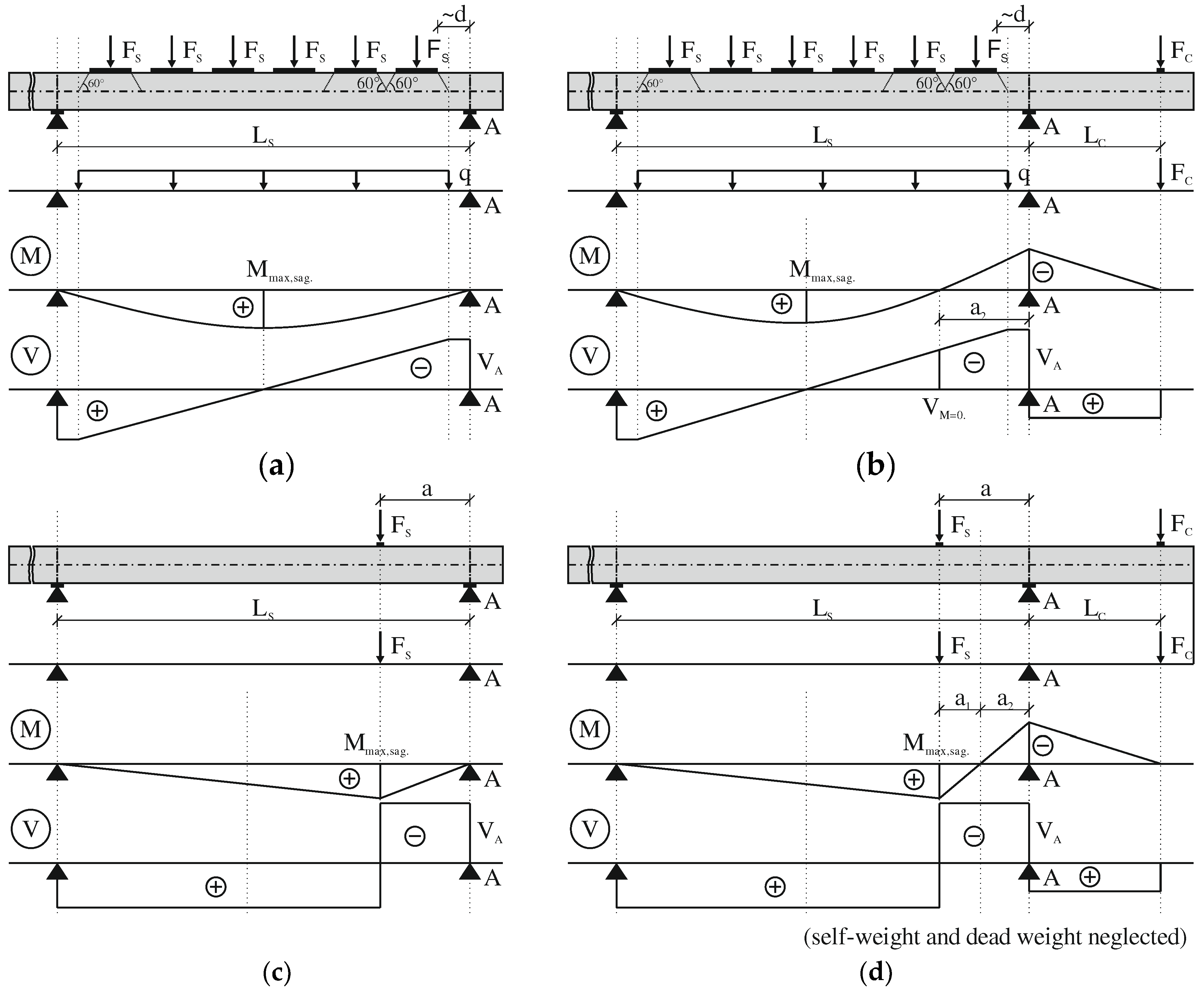
The shear tests differ in terms of support and load conditions. The type of static system (S1 to S4) is defined as follows:
System 1 (S1): simply supported member with a concentrated load (CL);
System 2 (S2): simply supported member with a cantilever (intermediate support on one side) and CL;
System 3 (S3): simply supported member with uniformly distributed load (DL);
System 4 (S4): simply supported member with a cantilever (intermediate support on one side) and with DL.
Systems 2 and 4 are substitute systems to simulate a continuously supported member. The cantilever was subjected to a concentrated load, generating a hogging moment at the intermediate support axis. The degree of rotational restraint, and thus the location of the point of contraflexure of the bending moment in the span can then be controlled by the ratio between cantilever load
and the load between the supports
or
, i.e.
. The schematic test setup of the systems S1 to S4 as well as the corresponding bending moment and shear diagram are shown in
Figure 1.
Apart from varying the degree of rotational restraint, the span length was varied, as well leading to a variation of shear slenderness .
Generally, the shear slenderness
is described as:
where
is the acting moment,
the acting shear force and
the effective depth of the member. In this paper, the self-weight of the specimens and the dead weight of the test setup are considered.
All specimens were tested in two subsequent partial tests. Both ends of each specimen were used for one test. During the first partial test, the area of interest of the second partial test remained unloaded. This eliminates any negative effect of the first partial test on the second partial test due to previous damage. This procedure led to specimens with a length up to 11.5 m. However, it saved a lot of material and was therefore preferable for economic and ecological reasons. If each specimen had been tested only once, the material consumption would have been 31.5 % higher in relation to the actual consumption.
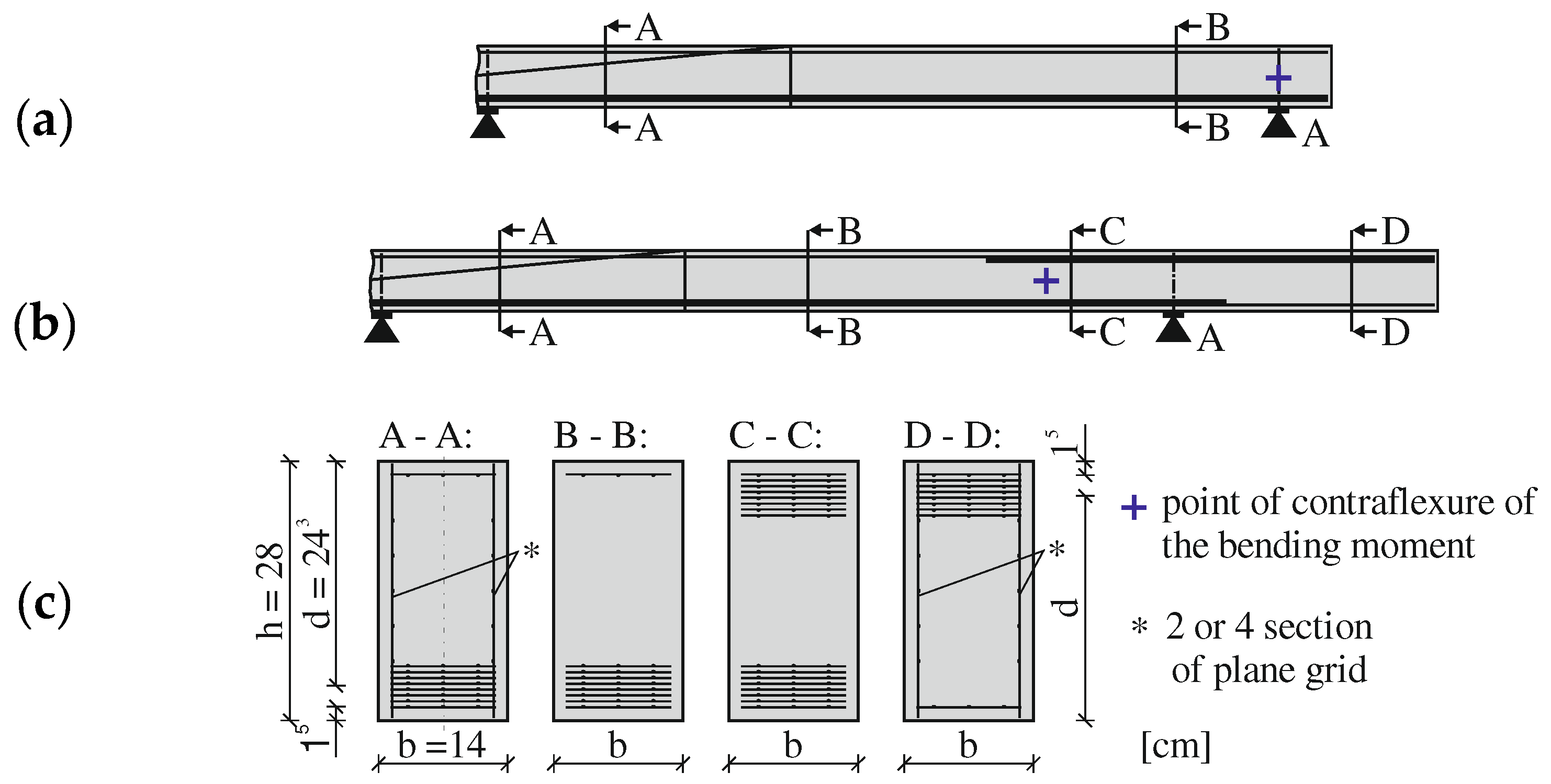
All specimens had a constant rectangular cross section with a width
of 0.14 m and a height
of 0.28 m (see
Figure 2 (
b)). Both, the flexural reinforcement in the area of the sagging and hogging moment consisted of eight layers of a grid-like CFRP reinforcement (see
Figure 2 (
a)). Each layer contained three yarns in warp direction. The layers were installed with a small distance between each other in accordance with the maximum aggregate size
of 4 mm. The staggered laps of the longitudinal reinforcement were placed outside the investigated area and were 0.2 m. The bottom multilayer flexural reinforcement was always extended over the support axes and the cantilever flexural reinforcement was well anchored in the sagging moment area. One layer was chosen as secondary reinforcement in the compression zone. The effective depth was about 0.24 m. The concrete cover was 15 mm on all sides. The specimens did not contain any shear reinforcement in the area of interest. Only the middle area of the specimens, which was loaded in the first and second partial test, and partly also the cantilevers, were shear reinforced with two or four sections of plane CFRP reinforcement.
Table 1 gives an overview of the test program, including main system parameters. The naming convention of the tests consists of the series (S1 to S4), the span length
and a consecutive number for each series-span combination.
2.2. Materials
For all test specimens the same composite materials were used. The concrete was a self-compacting, high strength concrete with a compressive strength class of C100/115 and consistency class F6 in accordance with [
25,
26]. The concrete mix design is shown in
Table 2. The maximum aggregate size
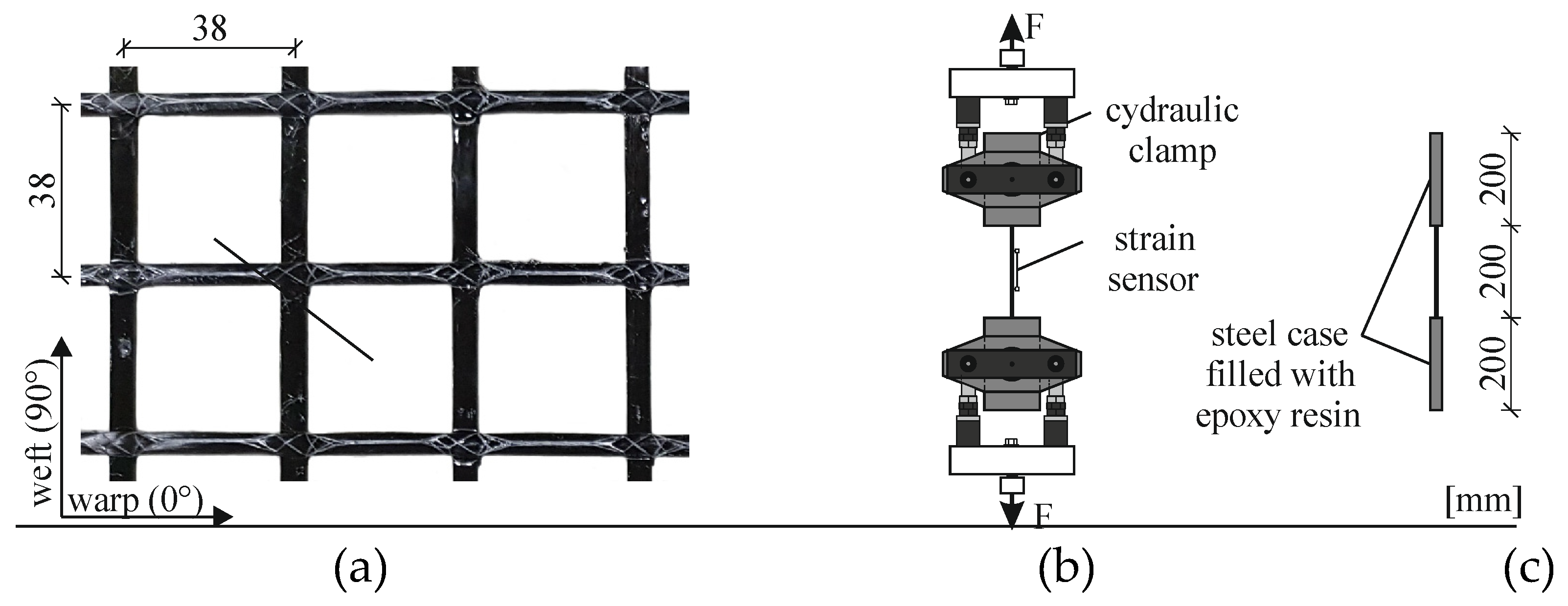
dg was 4 mm and was thus suitable for the use in combination with the used grid reinforcement with the mesh sizes given in
Figure 3 (a), in order to avoid a sieving effect during concreting and to ensure the compaction of the concrete. Material tests were carried out using cylinders (Ø 150 mm, h = 300 mm) and cubes (150 x 150 x 150 mm
3) according to DIN EN 196-1 [
26] on the day of the large-scale tests (cf.
Table 4).
Figure 3 (
a) shows the used CRFP reinforcement. It is an epoxy impregnated planar grid with two rovings per yarn in weft and warp direction. The grids had a standard size of 6 m x 3.2 m and were cut by an electric circular saw or band saw. Tensile tests on single yarns were carried out to determine the uniaxial material property such as tensile strength
fnm,u and the Young’s moduls
Enm of the reinforcement (subscript nm – non-metallic). Due to the anisotropy of CFRP, it is sensitive to transverse pressure. To avoid damage, the yarn’s ends were cast in steel sleeves with epoxy resin instead of directly clamped. The geometrical parameters and material properties are listed in
Table 3.
2.3. Test Setup
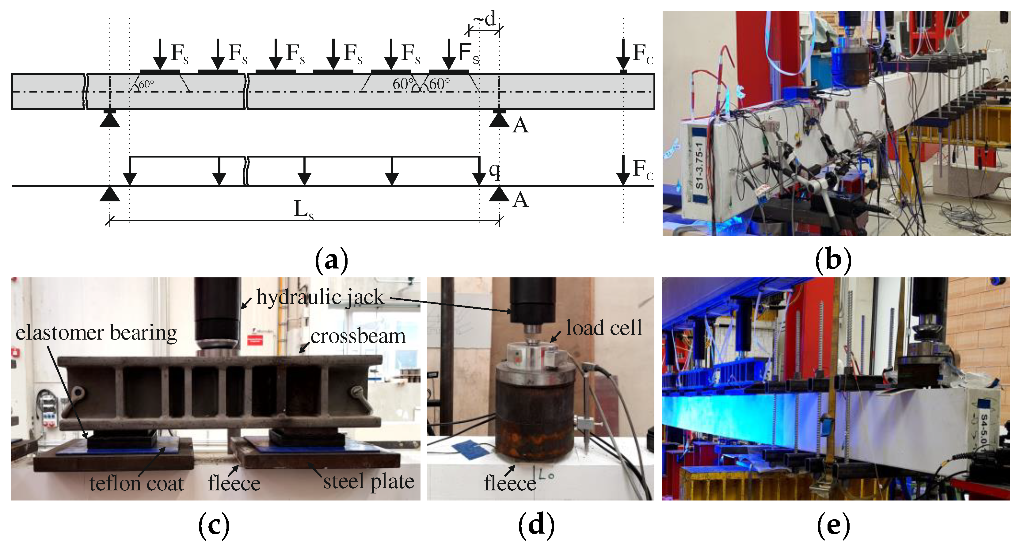
The experimental setups are shown in
Figure 4 with the examples of a simply supported member with a concentrated load (S1) and a simply supported member with intermeditate support and distributed loading (S4). All tests were performed force-controlled. That was essential for the specimens with a load between the supports and at the cantilever (i.e. S2, S4) and for the distributed loading (i.e. S3, S4) due to the used type of load introduction. The distributed loading was realized via equidistant concentrated loads (c.f.
Figure 4 (
a)), whereby a force of a hydraulic jack was always distributed via a crossbeam to two load introduction plates (c.f.
Figure 4 (
c)). The hydraulic jacks for the loading in the span were connected in one hydraulic cicruit, while the cantilever load was in a separate hydraulic circuit. As a result, for distributed loading, a uniform distribution of pressure despite variable deflections along the span was realized. The distance between the loads
was chosen so that their load dispersion lines overlapped on the neutral axis assuming a conservative load spread angle of 60° (see
Figure 4 (
a)). Moreover, the load application plate closest to the intermediate support was placed at a distance of approximately the effective depth
, to consider the direct load transfer to this support. Due to the setup of the load introduction of the distributed loading (c.f.
Figure 4 (
c)) horizontal displacements were possible and the vertical alignment of the single-acting hydraulic jacks were maintained. As shown in
Figure 4 (
e) the cantilever was externally strengthend to avoid early shear failure or heavy crack propagation in any case.
During the test, the deflection of the specimen was measured using inductive displacement transducers. In addition, in the area of expected shear failure, horizontal and diagonal displacement transducers as well as strain gauges were applied to one side to measure deformations and strains locally. This allowed the deflection and crack development to be observed during the test. On the opposite side, the strain states as well as crack formation were photogrammetrically captured using digital cameras with 6000 x 4000 pixels. Moreover, fiber optic sensors (FOS) were applied to the longitudinal reinforcement in selected tests to measure the longitudinal strain over the loading process.
3. Results
3.1. Shear Strength
The test results are summarized in
Table 4. The concrete properties as well as the acting forces are included. The ultimate shear force at the support A
closest to failure includes the self-weight of the test specimen and the dead load of the test setup, i.e., the load introduction. At this point, there is no reduction of the shear force due to direct strutting in case of distributed load. Depending on the degree of rotational restraint, and the areas of hogging and sagging moment, the critical shear crack formed from a flexural crack and propagated either from the top of the specimen towards the intermediate support or from the bottom of the specimen to the load introduction or midspan. The position of the initial point of the critical flexural crack (B – bottom, T – top) is also included in
Table 4.
Table 4.
Experimental results of shear tests.
In
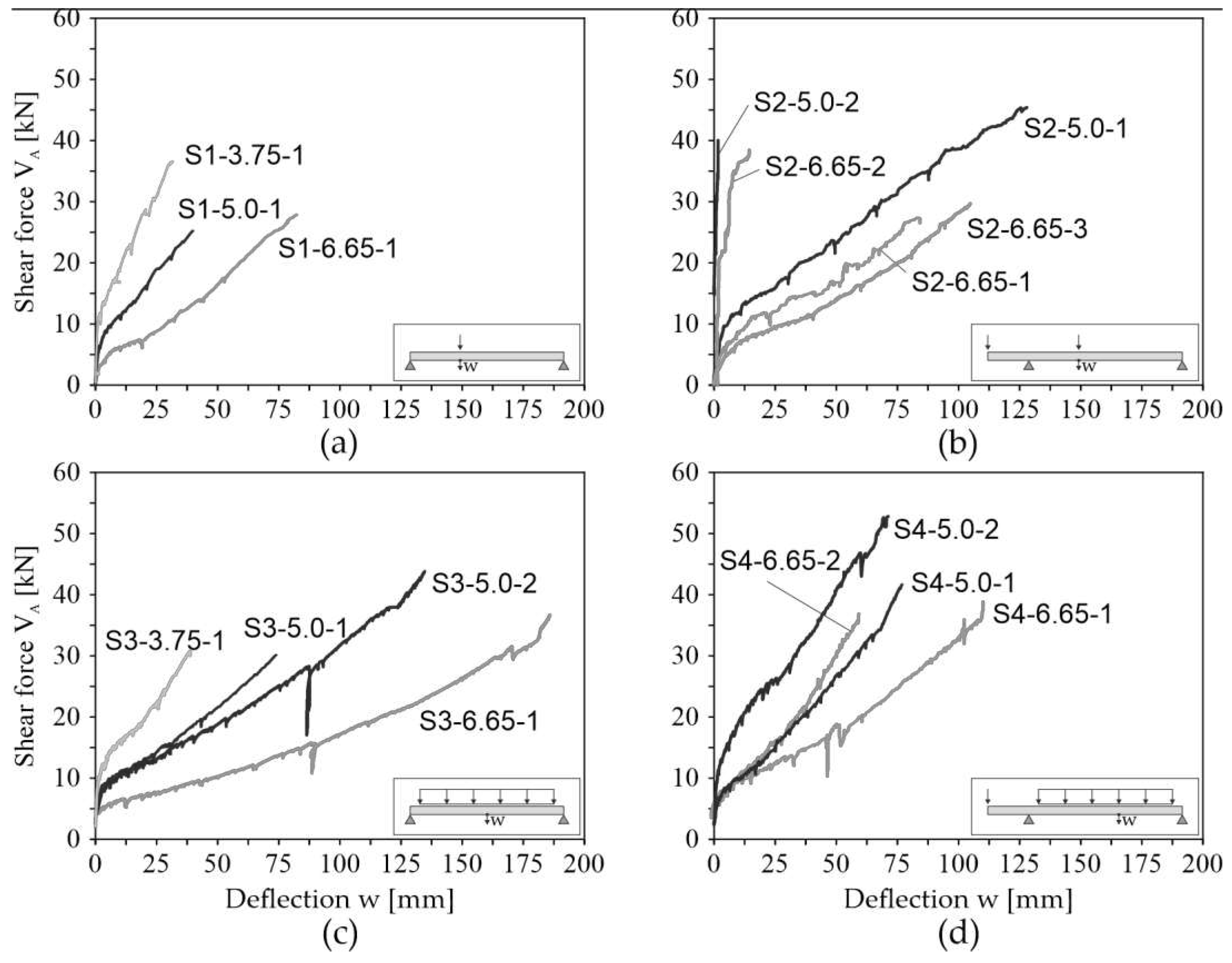
Figure 5 Figure 1the load-deflection curves of all tests are shown. The indicated shear forces
result from the applied loading
and
, respectively
, the self-weights of the specimens and the dead weights of the test setup. The indicated deflections were measured with LVDT placed underneath the specimens. For system S1 and S2, the deflection was measured in load axis, for S3 in midspan and for in the area of maximum bending moment. In general, it can be observed that smaller sagging moment segments result in to stiffer deformation behavior. The load drop in partial tests S3-5.0-1 and S3-6.65-1 (
90 mm) and S4-6.66-1 (
44 mm) can be explained by the fact that the tests were stopped for a short time. During the break, distance pieces were placed under the cylinders to be able to apply the expected deflection with the defined maximum stroke of the cylinders.
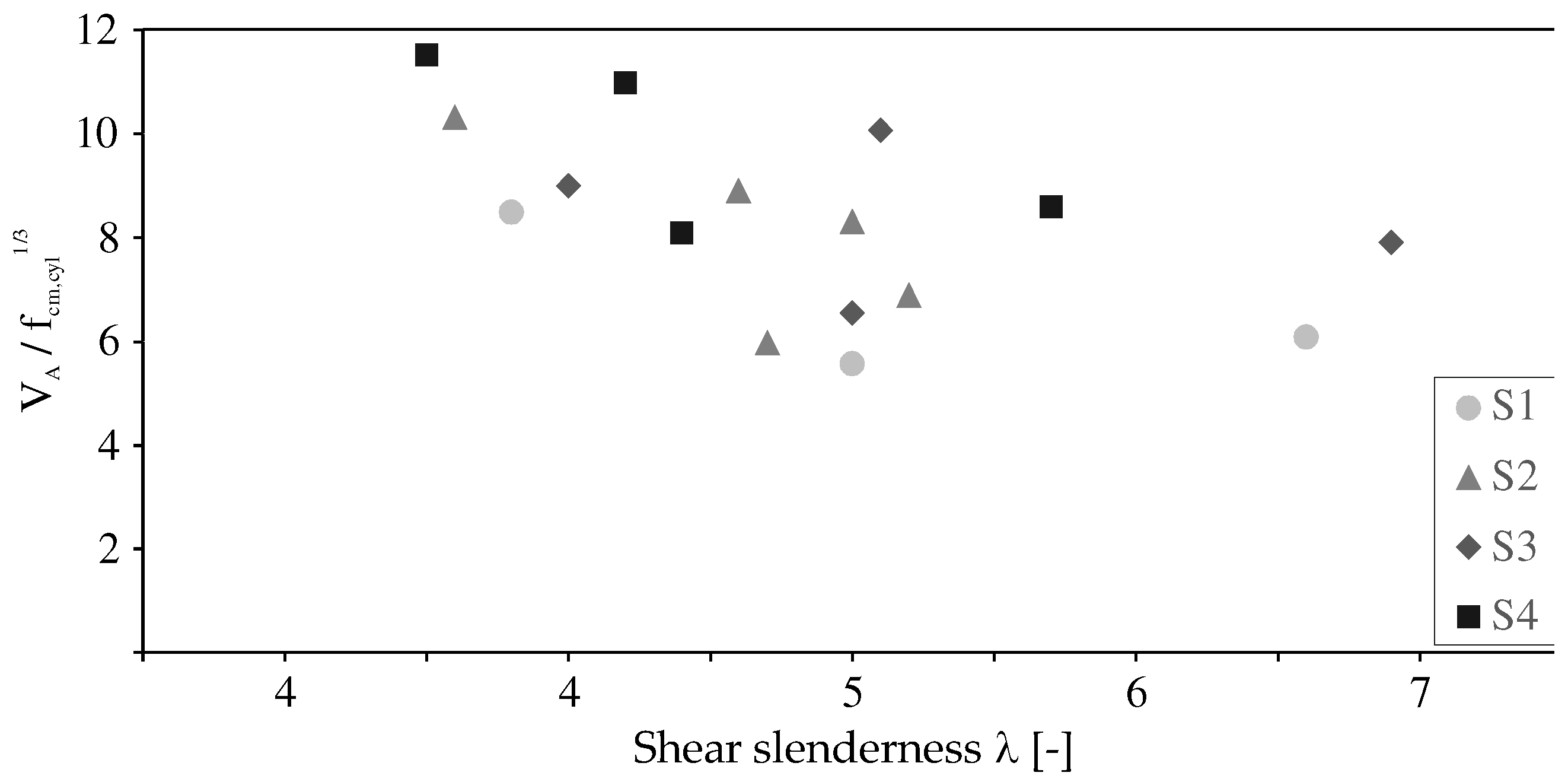
Figure 6 shows the influence of shear slenderness on the shear force at the support A in relation to the concrete compressive strength. As expected, low shear slenderness results in higher shear capacity, regardless of the load and support conditions. A comparison of the test results of series S2 and 24 with the series S1 and S3 shows that, on average, members with intermediate supports on one side (S2 and S4) and similar shear slenderness have higher shear capacities than simply supported members (S1 and S3). In addition, distributed loads have a positive effect on the shear capacity, provided that the support conditions are the same.
3.2. Failure Mode and Crack Pattern
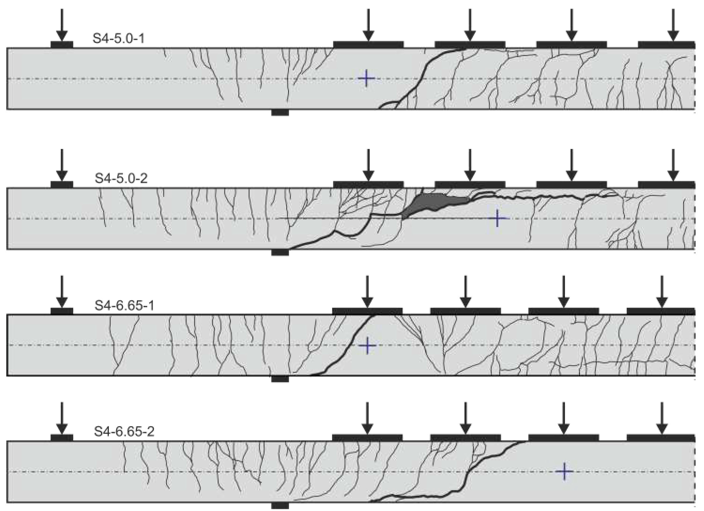
The desired flexural shear failure was observed in all 16 tests. The critical shear crack formed from an existing flexural shear crack, which ultimately extended rapidly into the compression zone, leading to a sudden shear failure by crushing of the concrete compression zone. However, failure was announced before ultimate failure by very large deflections and a disproportional increase in crack width. Crack propagation was documented at the side with conventional measuring technique at each loading step by keeping the deflection of the specimen constant and marking the cracks on the specimen’s surface.
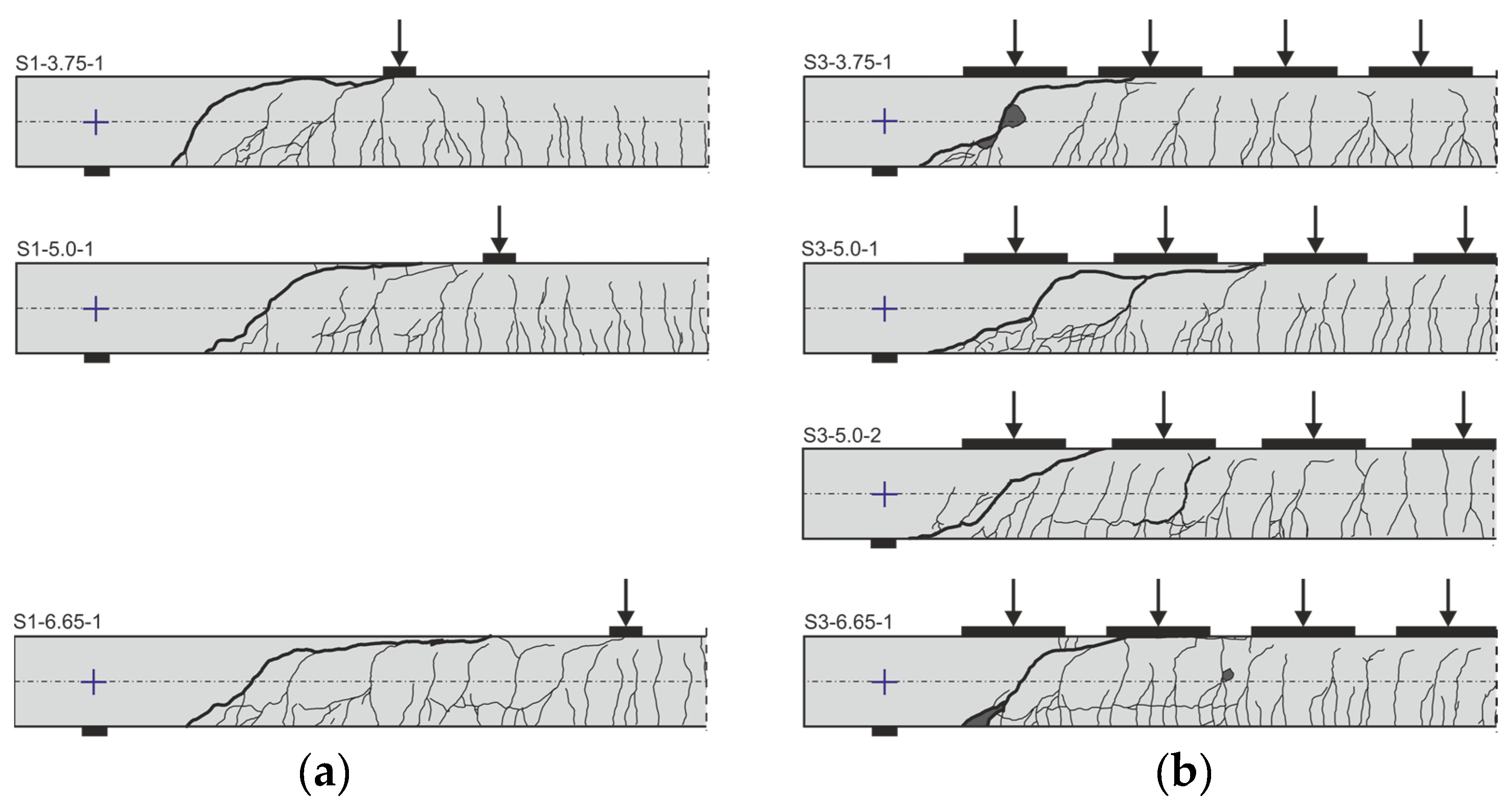
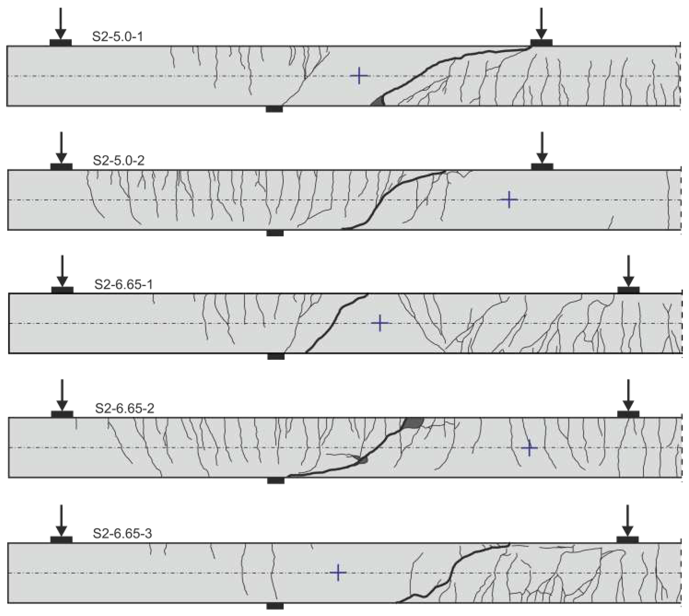
Figure 7,
Figure 8 and
Figure 9 show the crack pattern after shear failure for all 16 tests. The point of contraflexure of the bending moment is marked with a purple cross. In all tests, the crack pattern was characterized by small crack distances and therefore relatively small crack widths.
The distance of the intersection of the critical shear crack with the neutral axis to the support axis is nearly the same for simply supported members with concentrated and distributed load (c.f.
Figure 9). The flat angle of the shear crack in the tensile zone is clearly pronounced for members with distributed loads. Recent tests on the influence of the crack angle on dowel action for CFRP reinforced concrete members showed that this influences the contribution of the dowel action [
27].
The tests S3-5.0-1 and S3-5.0-2 show that the crack pattern can differ significantly although the test parameters are kept constant (
, DL). This also explains the different capacities of the tests (c.f.
Table 4).
Figure 8 shows the crack patterns of the simply supported members with cantilever and concentrated loads. Basically, the cracking is as expected and the critical shear crack forms depending on the hogging or sagging moment. Comparing the crack patterns of S2-6.65-1 and S2-6.65-3, the point of contraflexure of the bending moment differs only slightly, but the location and form of the shear cracks are very different. This is also expected to have a significant impact on several shear transfer actions.
Figure 9 shows the crack pattern of the simply supported members with cantilever and distributed loading. The critical shear crack of test S4-5.0-2 is particularly prominent in terms of its shape. Moreover, in no other test the critical shear crack has grown so far along the top longitudinal reinforcement into the compression zone.
4. Conclusion and Outlook
In this paper, sixteen CFRP reinforced concrete members were investigated in large-scale tests under shear load. The focus was on the influence of the support conditions, i.e. simply supported members with and without intermediate support, and load condition, i.e. concentrated and distributed loading, on the shear behavior. All test specimens failed due to flexural shear and had fine crack patterns as well as fine crack width. The critical shear cracks were identified by a disproportionate increase of the crack width at very high load levels. The brittle failure was announced by very large deformations. Moreover, the shape of the critical shear crack varied depending on support conditions and load arrangements as well as the span length. It can be assumed that this has a great influence on the shear transfer and failure mechanisms.
In summary, the assumptions derived from (steel) reinforced concrete members regarding the positive influence of continuous systems and distributed loads on the shear behavior could be confirmed. This is of great importance as it underlines the need to consider system parameters in design regulations. Based on the extended experimental database, appropriate models can be developed to better predict the shear strength. This is accompanied by more economical dimensioning and more efficient use of materials.
In current investigations of the presented shear tests, digital image correlation is used to analyze crack kinematics as well as the strain states of the uncracked compression zone during the loading process. Based on the analyses, the shear transfer actions, such as aggregate interlock, strength of the uncracked compression zone and dowel action will be investigated.
Author Contributions
Sarah Bergmann is a Research Associate at the Institute of Structural Concrete of the Faculty of Civil Engineering at RWTH Aachen University, Germany. She received her master’s degree in civil engineering from RWTH Aachen University in 2016. Her main field of research is the shear behavior of CFRP reinforced concrete structures and the strengthening of reinforced concrete structures with carbon reinforced concrete. Martin Claßen is the director of the Institute of Structural Concrete at RWTH Aachen University since 2021. His research interests include the steel-concrete composite systems, 3D-concrete printing as well as the load and deformation behavior of steel, carbon reinforced and prestressed concrete structures. He is a member of the International Federation for Structural Concrete (fib) and the International Association for Life-Cycle Civil Engineering (IALCCE). Since 2021, he has been member of the Belgian working committee BBRI-SECO/E25002. Josef Hegger was the director of the Institute of Structural Concrete at the RWTH Aachen University from 1993 to 2023. His fields of research include load-bearing and deformation behavior as well as steel and textile reinforced concrete, prestressed concrete, and composite concrete construction. He is member of several expert committees within the Deutsches Institut für Bautechnik (DIBt) and the International Federation for Structural Concrete. Since 2009, he is a convenor of CEN/TC 250/SC 2/WG1/TG4 ‘Design of concrete structures’ (Eurocode 2).
Funding
This research was funded by the Deutsche Forschungsgemeinschaft (DFG, German Research Foundation) – Project-ID 417002380 – TRR 280.
Acknowledgments
The authors thank the solidian GmbH for providing the CFRP reinforcement.
Conflicts of Interest
The authors declare no conflict of interest. The funders and sponsors had no role in the design of the study; in the collection, analyses, or interpretation of data; in the writing of the manuscript; or in the decision to publish the results.
References
- Leonhardt, F.; Walther, R. Shear tests on simply supported RC beams with and without shear reinforcement (in German: Schubversuche an einfeldrigen Stahlbetonbalken mit und ohne Schubbewehrung). 1962, vol. 151. Berlin (Germany), Ernst & Sohn.
- Kani, G.N.J. The Riddle of Shear Failure and Its Solution. Journal of the American Concrete Institute, 1964, 61(4), pp. 441-467. [CrossRef]
- Islam, M.S.; Pam, H.J.; Kwan, A.K.H. Shear Capacity of High-Strength Concrete Beams with Their Point of Inflection within the Shear Span. Proceedings of the Institution of Civil Engineers – Structures and Buildings, 1998, 128(2), pp. 91-99. [CrossRef]
- Campana, S.; Fernández Ruiz, M.; Anastasi, A.; Muttoni, A. Analysis of shear transfer actions on one-way RC members based on measured cracking pattern and failure kinematics. Magazine of Concrete Research 2013, 65(6), pp. 386–404. [CrossRef]
- Cavagnis, F., Fernández Ruiz, M., Muttoni, A. Shear failures in reinforced concrete members without transverse reinforcement: An analysis of the critical shear crack development on the basis of test results. Engineering Structure 2015, 103, pp. 157–73. [CrossRef]
- Huber P, Huber T, Kollegger J. Investigation of the shear behavior of RC beams on the basis of measured crack kinematics., Engineering Structure 2016, 113, pp. 41–58. [CrossRef]
- Adam, V.; Classen, M.; Hillebrand, M.; Hegger, J. Shear in Continuous Slab Segments without Shear Reinforcement under Distributed Loads. Proceedings of the fib Symposium 2019: Concrete - Innovations in Materials, Design and Structures, 2019, Krakow, Poland.
- Adam, V. Shear in Reinforced Concrete Structures – Analysis and Design. Dissertation, 2021, RWTH Aachen University, Germany.
- Trindade, J.C.; Garcia, S.L.G.; Lacerda, T. N; Resende, T. L. Analysis of the shear behavior of reinforced recycled aggregate concrete beams based on shear transfer mechanisms, Engineering Structures 2023; 293:116616. [CrossRef]
- Gomes, T.; Resende, T.; Cardoso, D. Shear-transfer mechanisms in reinforced concrete beams with GFRP bars and basalt fibers. Engineering Structures 2023, 289:116299. [CrossRef]
- Bielak, J. Shear in slabs with non-metallic reinforcement. Dissertation, Institute of Structural Concrete, RWTH Aachen University, 2021.
- Bielak, J.; Hegger, J.; Chudoba, R. Towards Standardization. Testing and Design of Carbon Concrete Composites. In High Tech Concrete. Where Technology and Engineering Meet, Proceedings of the 2017 fib Symposium; Maastricht, The Netherlands, 12–14 June 2017, Hordijk, D.A., Lukovi´c, M., Eds.; Springer International Publishing: Cham, Switzerland, 2017; pp. 313–320. ISBN 3319594710. [Google Scholar]
- Liebold, F.; Bergmann, S.; Bosbach, S.; Adam, V.; Marx, S.; Claßen, M.; Hegger, J.; Maas, H.-G. Photogrammetric Image Sequence Analysis for Deformation Measurement and Crack Detection Applied to a Shear Test on a Carbon Reinforced Concrete Member in: Ilki, A.; Çavunt, D.; Çavunt, Y. S. [eds.] Building for the Future: Durable, Sustainable, Resilient – Proc. of fib Symposium 2023, 05.–07.06.2023 in Istanbul (Turkey), publ. in: Lecture Notes in Civil Engineering 350, Cham: Springer, 2023, pp. 1273–1282. [CrossRef]
- DAfStb-Richtline. Beton mit nichtmetallischer Bewehrung, 2023, Weißdruck, Beuth, Berlin.
- Scholzen, A.; Chudoba, R.; Hegger, J. Dünnwandiges Schalentragwerk aus textilbewehrtem Beton – Entwurf, Bemessung und baupraktische Umsetzung in: Beton- und Stahlbetonbau, volume 107, issue 11, 2012, pp. 767–776.
- Helbig, T.; Unterer, K.; Kulas, C.; Rempel, S.; Hegger, J. Fuß- und Radwegbrücke aus Carbonbeton in Albstadt-Ebingen. Beton- und Stahlbetonbau, vol. 111, issue 10, 2016, pp. 676–685. [CrossRef]
- Ehlig, D.; Schladitz, F.; Frenzel, M.; Curbach, M. Textilbeton – Ausgeführte Projekte im Überblick. Beton- und Stahlbetonbau 107, Issue 11, 2012. [CrossRef]
- ACI 440.1R-15. Guide for the Design and Construction of Structural Concrete Reinforced with Fiber-Reinforced Polymer (FRP) Bars. American Concrete Institute, 2015, Farmington Hills, Michigan, U.S.A.
- CSA S806-12:2017. Design and construction of building structures with fibre-reinforced polymers, Reaffirmed 2017, Canadian Standards Association, 2012, Mississauga, Ontario, Canada.
- Machida, A. Recommendation for design and construction of concrete structures using continuous fiber reinforcing materials. 1997, Tokyo: Japan society of civil engineers.
- CNR-DT 203/2006. Guide for the Design and Construction of Concrete Structures Reinforced with Fiber-Reinforced Polymer Bars, 2007.
- Tung, N.D.; Tue, N.V. Effect of support condition and load arrangement on the shear response of reinforced concrete beams without transverse reinforcement. Engineering Structures, 2016, vol. 111, pp. 370-381. [CrossRef]
- Bergmann, S., Claßen, M., Hegger, J. Experimental study on the shear behavior of CFRP reinforced beams with shear reinforcement and intermediate support subjected to concentrated and distributed loading. Buildings 2023, ISSN 2075-5309. (submitted).
- Schneider, K., Butler, M., Mechtcherine, V. Carbon Concrete Composites C3—Nachhaltige Bindemittel und Betone für die Zukunft. Beton- und Stahlbetonbau 2017, 112, 784–794. [CrossRef]
- DIN EN 206. Beton—Festlegung, Eigenschaften, Herstellung und Konformität. Deutsches Institut für Normung e.V., Deutsche Fassung EN 206:2013+A1:2016; ICS 91.100.30; Beuth Verlag GmbH: Berlin, Germany, 2017.
- DIN EN 196-1. Methods of testing cement: Part 1: Determination of strength. Deutsches Institut für Normung e.V., German Version EN 196-1:2016, Beuth, Berlin.
- Bosbach, S. C.; Schmidt, M.; Claßen, M.; Hegger, J. Investigations on Dowel Action in Carbon Reinforced Concrete. In: Stokkeland, S.; Braarud, H. C. [eds.] Concrete Innovation for Sustainability – Proc. for the 6th fib International Congress 2022, 12.–16.06.2022 in Oslo (Norway), Oslo: Novus Press, 2022, p. 1809–1819.
|
Disclaimer/Publisher’s Note: The statements, opinions and data contained in all publications are solely those of the individual author(s) and contributor(s) and not of MDPI and/or the editor(s). MDPI and/or the editor(s) disclaim responsibility for any injury to people or property resulting from any ideas, methods, instructions or products referred to in the content. |
© 2023 by the authors. Licensee MDPI, Basel, Switzerland. This article is an open access article distributed under the terms and conditions of the Creative Commons Attribution (CC BY) license (http://creativecommons.org/licenses/by/4.0/).


