Preprint
Article

Precise Microwave Welding Induced by Localized Surface Plasmon: A Novel Way for Large-Scale Non-Metallic Material Joining with High Quality and Low Consumption

Altmetrics

Downloads

83

Views

23

Comments

0

This version is not peer-reviewed

Submitted:

10 December 2023

Posted:

12 December 2023

You are already at the latest version

Alerts
Abstract
Traditional methods of non-metallic materials joining for industrial uses are limited to lasers, or induction or conduction heating. The precision and efficiency for large-scale applications are difficult to be achieved at the same time. Here in this paper, we report a precise microwave welding method induced by localized surface plasmon of metallic macro-gaps under microwave excitation. The proposed method utilizes energy from well-developed commercial microwaver, and benefits from the precision of localized surface plasmon, an oscillating electron cloud excited by electromagnetic waves, which is currently under hot investigation only at micro- or nano-scales. The method is applied to the welding of polymers to solve the problems of complex processing equipment and high processing energy consumption in the traditional welding process, so as to cope with the growing energy and environmental crisis. Finite element numerical simulations are used to study the distribution characteristics of electric fields and temperature fields. The results show that the process is a high quality, efficient, low consumption and environmentally friendly green process compared to traditional polymer welding methods.
Keywords: 
Subject: Engineering  -   Industrial and Manufacturing Engineering

1. Introduction

With the growing energy crisis, the lightweight has become an important consensus on the development of the mechanical manufacturing industry, thermoplastic polymers because of its light quality, simple processing and forming, strong mechanical properties, good corrosion resistance and low cost advantages(Ries et al., 2021; Song et al., 2019; Xu and Zhang, 2016), has been widely used in food, medical care, aerospace, petrochemical, packaging and other fields. The use of thermoplastic polymers to replace metal products has become one of the most important lightweight methods (Chen et al., 2022; Park et al., 2020; van Grootel et al., 2020). Since 1950, it has been estimated that 8.3 billion tons of polymers have been produced in the world and have continued to grow at a high speed, the material stratum almost exists in all aspects of human life (Jehanno et al., 2022; Walker and Rothman, 2020). However, because polymers are difficult to degrade, unengaged waste polymers will inevitably cause damage to the environment and ecology, and polymers that are decomposed into micro plastics will even enter the food chain, seriously affecting human life and health (Bank and Hansson, 2019; Zhu et al., 2018; Zhu, 2021).
Rising energy prices and public environmental awareness have prompted governments and enterprises to realize that resource and environmental sustainability is a priority in product manufacturing and recycling processes, which requires the search for more efficient and environmentally friendly new means of polymer processing and recycling (Chen et al., 2012; Gagliardi et al., 2019; Sweeney et al., 2020). Within this framework, the objective of this paper is to find new means of more efficient and convenient polymer linking for low energy consumption and high efficiency recovery while saving energy and protecting the environment.
All along, welding technology has been pursuing to reduce welding heat input and improve machining efficiency on the premise of satisfying the connection quality, which has promoted the development of modern welding technologies such as friction stir welding (Rathinasuriyan et al., 2021), ultrasonic welding (Bhudolia et al., 2020) and laser welding (Li et al., 2022). Although these technologies have significantly improved processing efficiency and processing quality compared with the traditional hot plate welding, they are still typical welding methods based on heat conduction, which make the molecules diffuse to form entangled molecular chains by heating the interface, so as to realize the connection of polymers (Cunha and Robbins, 2020; Huang et al., 2018; Li et al., 2018). Due to the low thermal conductivity of polymers, heat transfer in the welding process is a slow process, which determines that the shortcomings of high heat input and low welding efficiency are difficult to be fundamentally solved (Lambiase and Genna, 2020; Mehra et al., 2018; Sheikh-Ahmad et al., 2022). The laser transmission welding technology makes the heat directly act on the welding interface through the combination design of materials with different light transmittance, which solves the problem of low welding efficiency caused by low thermal conductivity of polymer to a certain extent(Acherjee, 2020; Chen et al., 2018; Schmailzl et al., 2020; Wang et al., 2021). However, the limitation of the process still leads to the problem of low welding efficiency of high light transmittance materials, which restricts the wide application of laser welding (Acherjee et al., 2011). Therefore, it is still an important challenge for the current manufacturing industry to seek for polymer welding methods with higher efficiency, higher quality and wider material applicability.
Microwave has unique characteristics different from other electromagnetic waves, such as short wavelength, high frequency and strong penetrability(El Khaled et al., 2018; Hattermann et al., 2017; Robinson et al., 2022). Besides being widely used in food heating and telecommunications industries, in recent years, people have paid more and more attention to its remarkable advantages in the fields of material processing such as drying, curing, casting and sintering, such as improving mechanical properties, reducing defects, economy and environmental protection, etc. (Potente et al., 2002; Yarlagadda and Chai, 1998; Yussuf et al., 2005). When a material is polarized in an alternating field, some energy will be lost in the form of heat, and the ratio of energy lost in each inversion process is dielectric loss. According to the characteristics of different dielectric loss materials with different microwave adsorption degrees, the dielectric polymer can be controllably heated by reasonably adjusting the matching relationship between microwave energy and material dielectric parameters(Lackinger, n.d.; Lutkenhaus, 2018; Yu et al., 2023; Zeng et al., 2020). Compared with convection heating, microwave heating consumes 10-100 times less energy and requires 10-200 times less time. As a new processing method with high quality, high efficiency and environment friendly, microwave welding is expected to replace laser transmission welding technology in polymer welding(Majdzadeh-Ardakani and Banaszak Holl, 2017). However, the non-uniform distribution of microwave power in the heating medium caused by factors such as the thermophysical characteristics of polymer and the non-uniform distribution of electromagnetic field intensity in the heating cavity will lead to local overheating problems such as thermal runaway (Bhattacharya and Basak, 2017; Sahota et al., 2020). In addition, the microwave frequency band that can be applied in the industrial field is only 915 MHz and 2450 MHz, which has a relatively long wavelength compared with the laser frequency segment, which leads to the difficulty of accurately focusing the microwave on the material to be processed in microwave welding to improve the machining accuracy and efficiency (Green et al., 2018; Hill and Jennings, 1993; Shao and Wang, 2019).
The plasmon effect of nanoparticles can make the light wave break through its diffraction limit and focus in the range smaller than its wavelength. In recent years, more and more researchers hope to apply the focusing property of plasmon effect to microwave and millimeter wave frequency, but unfortunately, the plasma frequency of metal is in infrared and optical bands, while in microwave and millimeter wave bands, the characteristics of metal are closer to ideal conductor than electric plasma, so there is no plasmon mode in microwave band (Li et al., 2020). In order to generate plasmons at microwave or terahertz frequency, researchers proposed in 2004 that plasma metamaterials with subwavelength structure should be made on metal surface to excite plasmons at microwave or terahertz frequency band. Artificial surface plasmons excited by plasma metamaterials inherit the field confinement and subwavelength resolution of natural plasmons (Pendry et al., 2004). Because the artificial surface materials excited by plasmons are very sensitive to the dielectric environment near the structure(Jun et al., 2021; Ni et al., 2020; Qian et al., 2021; Sun et al., 2019), it is expected to be applied in microwave welding, and provide a new solution in improving the efficiency, precision, freedom of machining and reducing the energy consumption of the microwave welding(Li et al., 2015; Olofinjana et al., 2001).
Based on this, this paper creatively applies the plasmon local field enhancement effect to the microwave welding field of dielectric polymer, and proposed a method of plasmon local field enhancement assisted microwave welding (PLFEMW), that is, by designing a specific metal macro-gap, the localized surface plasmon effect of microwaves is excited, so that the electromagnetic field intensity of microwaves is highly enhanced in localized areas, and the purpose of "focusing" microwaves is achieved. The "focused" microwave energy is applied to the welding area of the dielectric material, and the dielectric material itself loses the electric field energy in the alternating electric field and generates heat to melt the weld area and achieve the purpose of welding. In this paper, the local field enhancement characteristics of microwave energy and the heating characteristics of materials are studied by the finite element numerical simulation method. The feasibility of PLFEMW technology and the reliability of the model are verified by the welding test of PA66. Finally, the factors affecting the local field enhancement characteristics of microwave and the electromagnetic thermal characteristics of dielectric materials are analyzed by the finite element numerical simulation. The feasibility of PLFEMW under various working conditions was explored. The results have important guiding significance for the precise control of welding energy, position and size in the process of microwave welding.

2. Methodology

2.1. PLFEMW Processing Mode

Figure 1 shows the schematic diagram of PLFEMW welding processing. Figure 1a is the temperature distribution diagram of traditional microwave heating process, it can be seen that this self-heating mode, which relies on the polar functional groups inside dielectric materials to spontaneously generate heat with the change of high frequency of electric field, has a higher overall heating efficiency compared with traditional heating methods based on heat conduction (Ren et al., 2023). However, the self-heating mode of the "body heat source" which depends on the microwave energy field is also limited by the difficulty of focusing the microwave energy of long wavelength, and it is difficult to heat the large polar polymer in the microwave field locally. The proposed bimetallic sphere gap structure with sub-microwave wavelength can effectively inherit the field constraint and subwavelength resolution characteristics of natural plasmons, and can make microwave energy focus on precise sites far smaller than its original microwave wavelength. Moreover, the distribution of microwave energy in space can be controlled by changing the material, size and gap of the metal sphere (Figure 1b). Combining this simple microwave energy "focusing" mode with the "bulk heating" mode of polar polymer can effectively solve the problem that large polar polymer cannot be heated locally at fixed point in microwave field.
Figure 1c shows a schematic diagram of a precision microwave welding method combining the bimetallic sphere microwave energy "focusing" mode with the polar polymer "bulk heating" mode, i.e., the PLFEMW welding method. As shown in the figure, polymer gripped by bimetal ball is exposed to microwave environment, due to the local focusing effect of bimetal on microwave energy field, the electric field intensity inside polymer shows that the middle region is much higher than the surrounding region, so that only the central region of polymer can produce high temperature enough to melt itself due to dielectric loss, so as to achieve the purpose of fixed-point heating.

2.2. Electromagnetic—Thermal Coupling Model and Local Field Enhancement Characteristics

Based on the PLFEMW welding principle, a polymer microwave welding model is established, which utilizes the local field enhancement effect of plasmon excited by bimetallic balls. The model calculates the spatial distribution of the background electric field (Ea), the enhanced electric field (Eb) excited by the bimetallic balls, and the total electric field intensity (Ec) resulting from their superposition. Furthermore, employing the electromagnetic-thermal multi-physical field module, the model simulates the redistribution of heat between the polymer and the two metal balls through transient heat transfer simulation. Therefore, the polymer microwave welding model based on the local field enhancement effect of plasmon involves simultaneously solving the Maxwell electromagnetic equation coupled with the thermal equation. In order to investigate the effect of the dielectric constant of the material on the local field enhancement, and to simplify the calculation, the model assumes that the dielectric constant of the polymer does not change with the change of temperature. The equation to solve the electric field vector E in space is as follows:
× ( μ r 1 × E ) k 0 2 ( ε r j σ ω ε 0 ) E = 0
Where μr represents relative permeability, j represents imaginary unit, σ represents electrical conductivity, ω represents angular frequency, εr represents relative permittivity, and ε0 represents free space permittivity. The model uses material parameters for air: σ=0, μrr=1.
During the propagation of electromagnetic wave, part of the energy will be absorbed by the dielectric material, and the microwave power absorbed by the medium is equal to the electromagnetic power loss (dissipated power) in the medium during the microwave heating process. The dissipated power can be obtained by electromagnetic wave equation and Poynting theorem. When considering time-harmonic electromagnetic fields, the integral form of Poynting's theorem is as follows:
S S d s = 1 2 ω ε V E E * d v + i ω 2 V ( μ 0 H H * + ε E E * ) d v
In the formula, E* and H* represent conjugated electric and magnetic fields respectively, S is the closed boundary surface of the medium, and V is the space region of the medium. Poynting's theorem shows that when electromagnetic wave propagates in a medium, the dissipation of electromagnetic wave power, that is, the absorbed power of the medium, is related to the characteristics of the electromagnetic field and the dielectric properties of the medium.
The electromagnetic energy is dissipated inside the medium and converted into the heat energy of the medium. Combining the principle of conservation of energy and Fourier heat conduction law, the heat balance equation in the heating process of the medium can be described by the thermal diffusion equation in which the dissipated power is the internal heat source term as follows:
ρ ( T ) C P ( T ) = · ( k ( T ) · T ) + P ( r , T )
In the formula, T is the temperature of the medium at t time during the heating process,ρ(T), CP (T) and k(T) are the density, specific heat capacity and heat conduction coefficient of the heating medium, respectively, the heat transfer mechanism of the medium itself is mainly described by the dispersion ∇∙(∇∙T), P(r, T) is the internal heat source term, that is, the instantaneous dissipation power of electromagnetic wave.
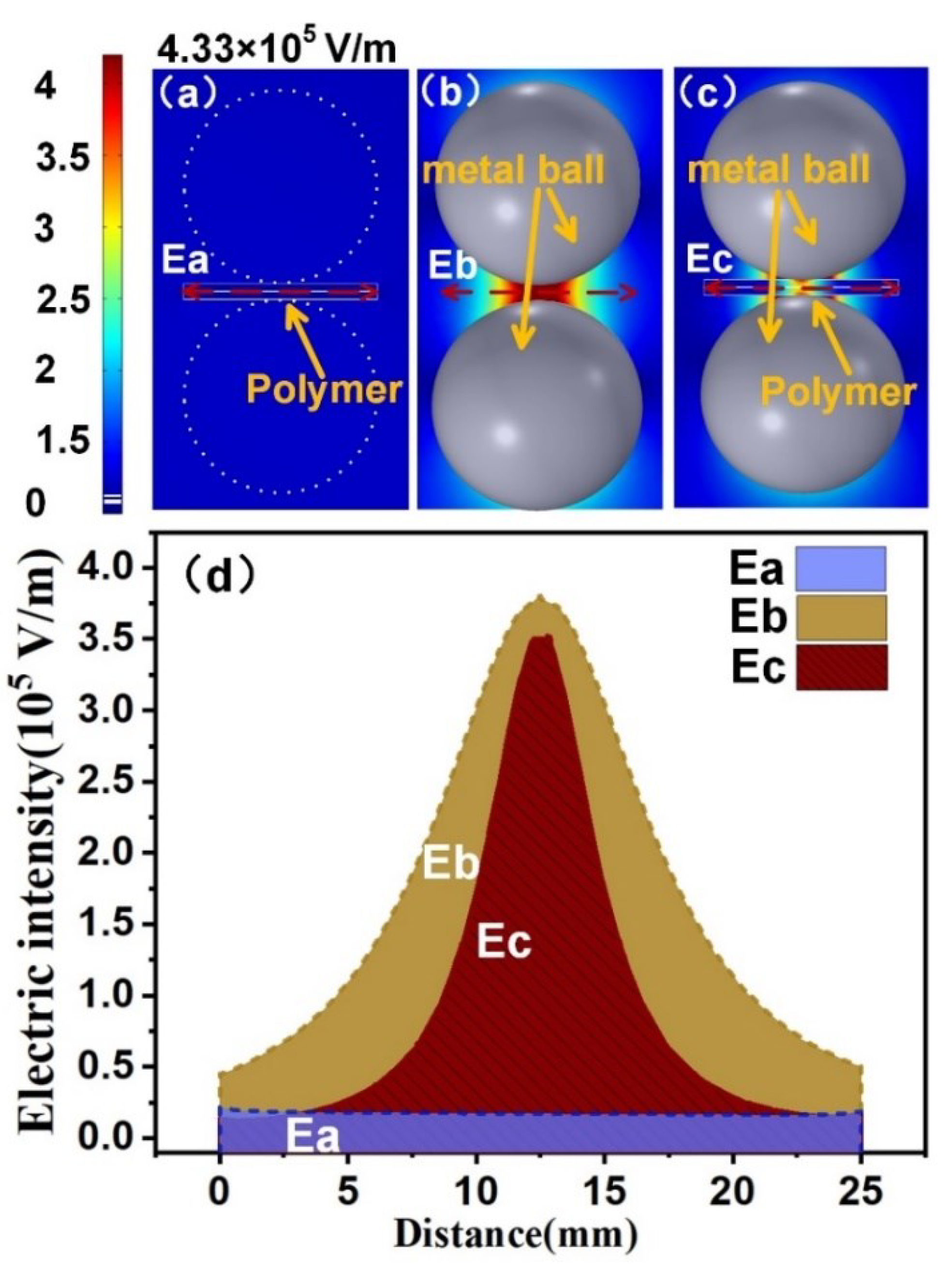
The distribution characteristics of background electric field Ea, enhanced electric field Eb, and total electric field strength Ec were compared (Figure 2a–c), and the distribution characteristics of electric field, total power density, and temperature inside the polymer were analyzed (Figure 2d). Compared with the background electric field Ea with lower intensity and more uniform distribution, Eb showed a significant electric field "focusing" effect, and the enhancement area was in the gap part of the bimetallic sphere, showing a trend of high intensity in the middle and low intensity around. The total electric field Ec indicates that the "focusing" effect of the microwave energy field of the bimetallic sphere can well focus the microwave energy in the internal region of the polymer, and realize the fixed-point microwave energy enhancement inside the polymer. Figure 2 (d) shows the distribution curve of the electric field intensity on the dotted line inside the polymer. It can be seen that the total electric field Ec inside the polymer has the same distribution trend as the enhanced electric field Eb, which increases by ten times compared with the background electric field Ea.
Factors such as the physical characteristics of the polymer and the uneven distribution of electromagnetic field intensity will cause the uneven polarization degree of the polymer, resulting in Thermal runaway and uneven heat distribution in the heating process, and then resulting in incomplete interface blending, weld cracking, edge scorching and stress concentration of the welding parts. Therefore, it is important to explore the electric field intensity, total power density and temperature distribution characteristics in the polymer to guide the PLFEMW process.
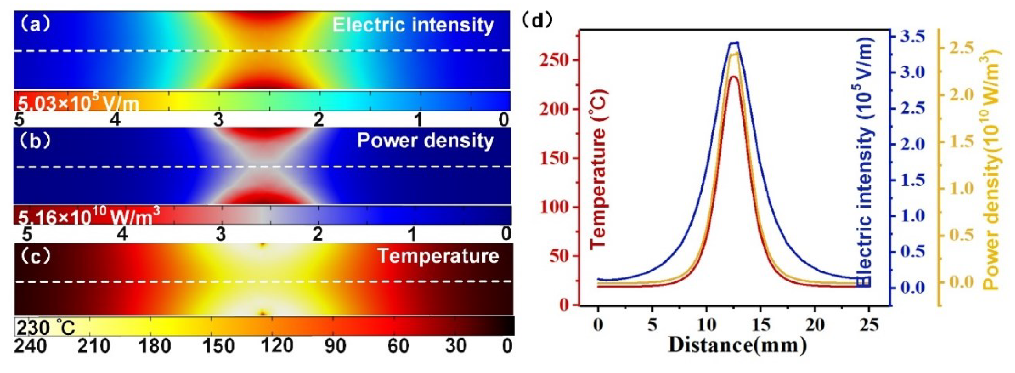
Figure 3a–c respectively show the distribution of electric field intensity, total power density and temperature inside the polymer film calculated by finite element numerical simulation. (d) shows the distribution curve of electric field intensity, power density and temperature in the transverse direction of the solder joint. It can be seen that with the increase of depth of the polymer, the intensity of electric field has the exponential attenuation trend, this is because the electromagnetic wave from the polymer surface enters and spread in them, are constantly absorbing and translated into heat energy, the energy they carry it will with further distance on the surface of the polymer, the exponentially decay, its penetration depth is given by the following formula:
D = λ 0 2 π ε 0 · tan δ
As can be seen from equation (4), the penetration depth of microwave to dielectric material is positively correlated with the wavelength. Since the wavelength of microwave is long, which is nearly one thousand times that of infrared band, the heating depth of microwave is much larger than that of infrared band. Compared with the traditional surface heating method, the in-situ heating method deep into the material has a smaller temperature gradient inside the material, which can better control the melting degree of the material in the process of polymer welding and promote the uniformity of welding. The intensity distribution of the temperature field has the same trend as the electric field intensity and power consumption density, indicating that compared with the heat conduction, the heat generated by the electromagnetic loss of the material itself is the main factor causing the melting of the welding interface, which provides the possibility to accurately control the position and size of the solder joint.

3. Experimental Procedure for PLFEMW Welding Trials

This section takes PLFEMW welding of engineering plastic PA66 as an example, based on the above ideal model, the test and finite element numerical simulation model (actual model) are redesigned: A pair of glass sheets is placed between a polymer and a bimetallic sphere to cool the polymer surface, Cu metal barrier and waveguide are installed to improve energy efficiency, a microwave source is added through a rectangular waveguide at the uppermost position in the middle of the left side of the metal barrier, the microwave is a rectangular waveguide operating in TE10 mode, and the rectangular port is excited by transverse wave (TE) with a frequency of 2450 MHz and a power of 800 W. The main physical parameters of PA66, metal ball and glass are shown in Table 1.
The experiment explored the heating effect of metal balls with different curvature radii (12.5, 17.5, 22.5, 27.5mm) on PA66 and carried out corresponding finite element numerical simulation. Real-time monitoring of temperature during processing was carried out by infrared thermal imager (600C, Fotric Inc., CHN) to verify the reliability of simulation results of temperature field. Finally, a universal testing machine (5956, Instron Inc., USA) was used to test the tensile properties of the welded samples under different curvature radius conditions, and the field emission scanning electron microscope (MIRA 3, TESCAN Brno, s.r.o. Inc., Czech Republic) was used to observe the microstructure of the stretched samples, so as to evaluate the solder joint properties of PLFEMW welded samples.

4. Results and Discussions

4.1. Temperature

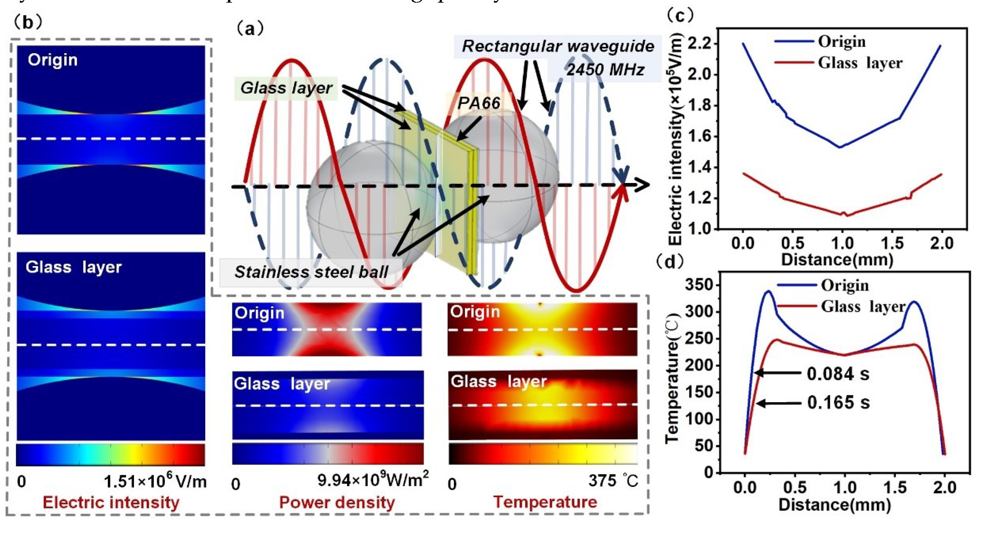
Figure 4a is the schematic diagram of PLFEMW welding process of PA66 after glass film is added; Figure 4b shows the distribution of electric field, total power consumption density and temperature inside polymer before and after glass film is added; Figure 4c,d are the comparison of electric field and temperature field curves in the depth direction of solder joint before and after glass film is added. It can be seen that the addition of the glass film layer effectively reduces the electric field intensity in the polymer surface area, and the temperature of the polymer surface layer is significantly lower than the center temperature of the solder joint due to the cooling effect of the glass layer with high thermal conductivity, thus avoiding the external burn of the welding sample. At the same time, the glass film layer will also make the metal ball exert uniform pressure on the polymer sheet, and improve the welding quality.
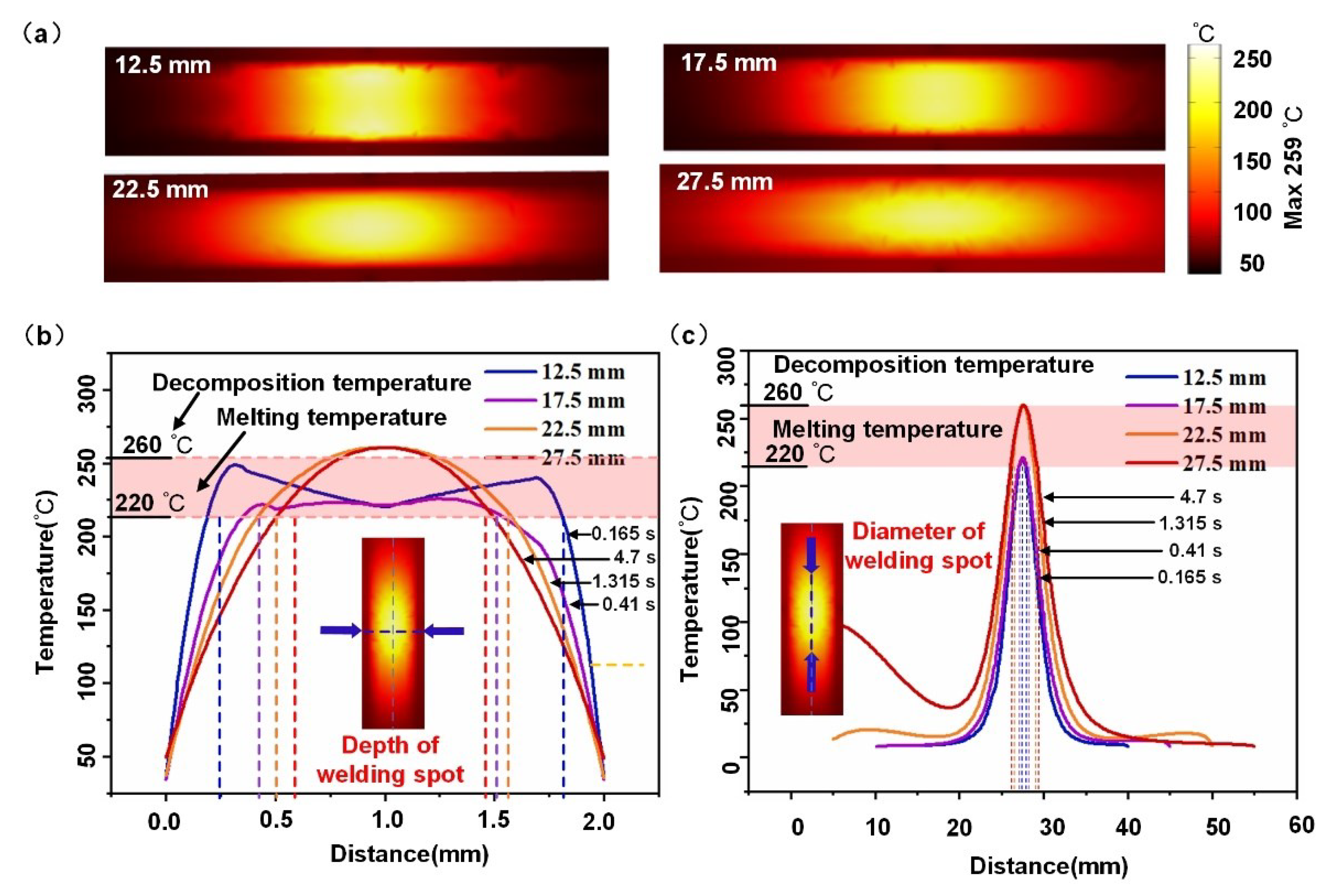
Figure 5(a), (b) and (c), respectively show the cross sections of temperature fields inside the polymer corresponding to models with different curvature radii, as well as the temperature curves in the depth and width directions of the solder joint. Among them, the temperature curves in the depth direction reflect the depth of the solder joint, and the temperature curves in the width direction reflect the diameter of the solder joint. It can be seen that under the condition of small curvature radius (12.5mm), the solder joint area is small, the temperature rises quickly, but the surface is easy to be damaged by heat; Although increasing the curvature radius will reduce the heating rate, it has the advantages of large solder joint area and low surface temperature (when the melting depth of the welding center area is about 1 mm, the surface temperature of the polymer is less than 50 ℃, far less than the melting temperature of the polymer).
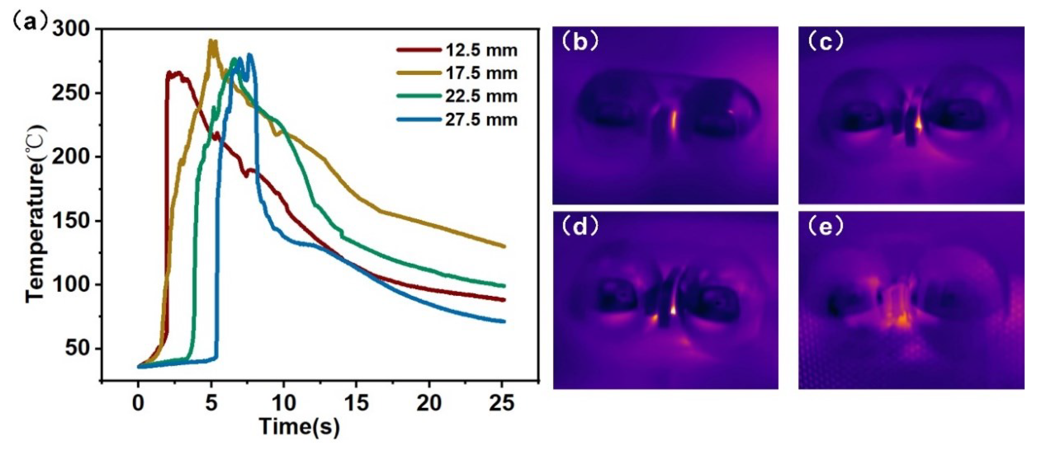
Figure 6a shows the change curve of solder joint temperature with time in the welding process under different curvature radii collected by infrared thermal imager. Figure 6(b), (c), (d) and (e), respectively show the temperature images under different radii. It can be seen that the solder joint is in a circular shape in the joint area of the two metal spheres, and the temperature in the center is the highest, and the gradient decreases from the center to the surrounding area, which is consistent with the temperature distribution trend obtained by finite element numerical simulation. When the curvature radius of the metal sphere is 12.5 mm, the welding spot has a very fast heating rate, with the increase of the curvature of the metal sphere, the heating rate slows down, which is consistent with the electric field intensity and temperature distribution obtained by finite element numerical simulation.

4.2. Mechanical Properties

Thermal loss caused by excessive or uneven electric field strength inside the polymer will cause pores and surface depression in local areas inside the material, and the solder joint morphology under different curvature radii is significantly different. Therefore, the tensile properties of the samples obtained under different curvature radii can be evaluated by tensile test.
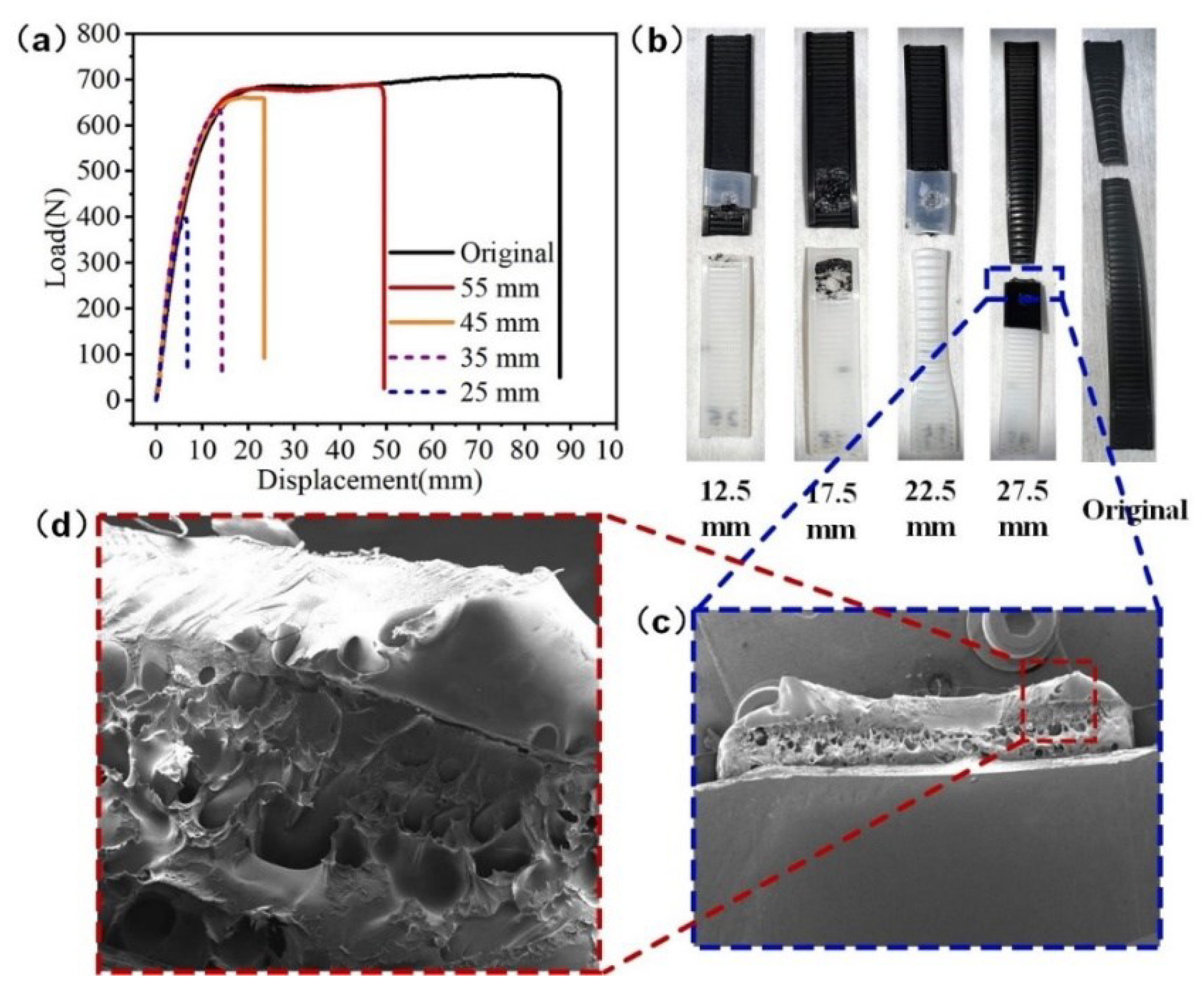
Figure 7a shows the tensile curves of welded samples and PA66 base material under different curvature radii, and shows the fracture morphologies of different samples after fracture (Figure 7b). It can be seen that the fracture behavior of samples obtained under different curvature radii is significantly different. Under the curvature radius of 12.5 mm and 17.5 mm, there is no obvious material yield stage in the tensile curves of the samples, the fracture locations are all in the interface area, and the maximum load of shear force at the fracture point is 397 N and 633 N, respectively, this is because the electric field with a small radius of curvature has a strong local enhancement effect. Although this condition has a very fast welding speed and a small diameter of solder joints, it also has the problems of thermal runaway and a large heat affected zone in the direction of welding depth. Excessive temperature will lead to the degradation of the bonding property of polymer due to high-temperature decomposition, and finally lead to the reduction of shear resistance of solder joints.
The tensile curves of samples with radii of 22.5 mm and 27.5 mm showed an obvious material yield stage, during the tensile process, the sample showed a shrinking neck at one side of the substrate, and then the deformation gradually expanded to the interface, finally, the fracture occurred at the connection position between the substrate and the welding interface under the action of tension. The maximum tensile strength of the 27.5 mm sample reached 688 N, which was similar to that of the base material. The above results are due to the fact that in the welding process of metal ball with large curvature radius, the electric field distribution inside the polymer is more uniform, the heat affected zone in the direction of welding depth is small and the solder joint area is large. These characteristics make the adhesion between the two samples strong and the solder joint has greater shear strength.
The strong electric field intensity also causes the polymer around the solder joint to have a certain thermal effect, resulting in slight pyrolysis of this part of the material in the welding process. Figure 7(c) and (d) respectively show the fracture morphology of the sample with a curvature radius of 27.5 mm and the local enlarged image of the fracture. It can be seen that there is an obvious necking phenomenon at the fracture, and there are slight defects and holes at the edge and inside of the fracture, which reduce the yield strength of the material to a certain extent. However, the ultimate tensile strength of PLFEMW welded samples has basically reached the level of the base material, and can meet the basic requirements of the quality standards for polymer welds in industrial applications.

4.3. Influencing Factors of Welding Performance of PLFEMW

In order to give full play to the unique advantages of PLFEMW welding and broaden the application range of PLFEMW in industrial welding, it is necessary to conduct numerical simulation analysis on the influencing factors of electric field and temperature field of the Electromagnetic - thermal coupling model. The heat of microwave welding is generated by the loss of the electric field energy of the polymer itself in the alternating electric field, the intensity of the electric field in space and the physical parameters of the polymer and their mutual influence jointly determine the generation and distribution of the heat in the process of polymer welding. Therefore, the study of the influence of different ball and polymer materials, ball curvature radius, microwave incident Angle and its frequency on the electric field and temperature field has important guiding significance for guiding the precise control of welding spot location and size in the process of microwave welding.
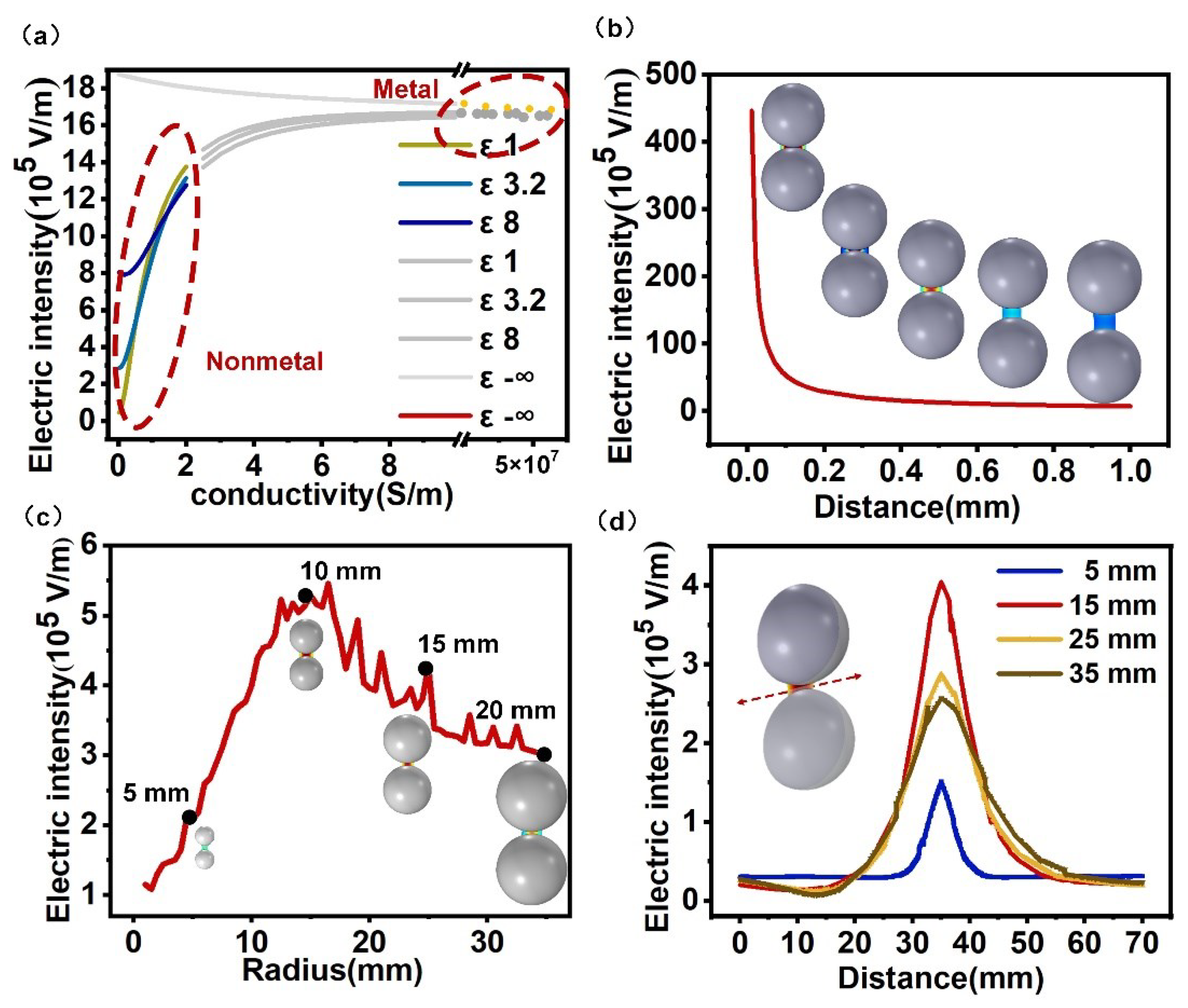
Figure 8 shows the influence characteristics of ball material, gap size and size on electric field intensity. Figure 8a shows that under different dielectric constants (ε=1, 3.2, 8, -∞, which are the typical representatives of non-polar, weakly polar, strongly polar and metal, respectively), the variation of electric field intensity in space with the conductivity shows that metal materials with high conductivity can play a significant "focusing" effect of microwave energy field. When the radius of the metal ball is 12.5 mm and the gap between the bimetallic balls is 0-0.2 mm, the "focusing" effect is strong, and the intensity decreases with the increase of the gap (Figure 8b). The variation curve of electric field intensity with the curvature radius of the metal ball is shown in Figure 8c. Figure 8d shows the electric field intensity curve on the dotted line under several typical spacing. It can be seen that the electric field intensity first increases and then decreases with the increase of the curvature radius of the metal ball, reaching the highest point when the curvature radius is 12.5-15mm. Under the condition of large curvature radius, the internal polymer has a lower gradient of electric field intensity.
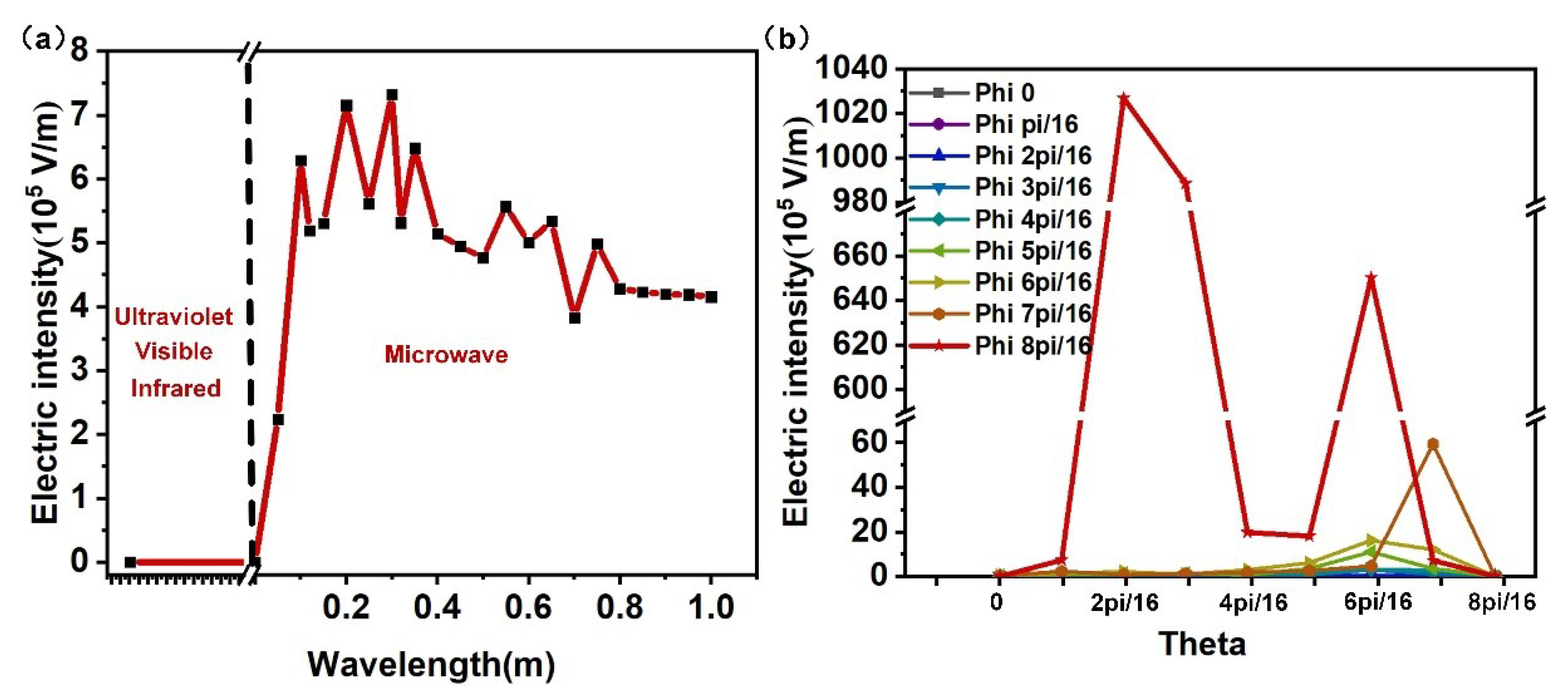
Figure 9 shows the influence of electromagnetic wave wavelength and incident Angle on electric field intensity when the curvature radius of the metal sphere is 12.5mm and the gap between the two spheres is 2 mm. The curve of electric field intensity with wavelength shown in Figure 9a shows that the wavelength range of ultraviolet wave, visible wave and infrared wave does not meet the subwavelength structure matching relation of the metal macro gap constructed in this paper. Therefore, the local field enhancement effect only occurs in the microwave wavelength band, and has a significant enhancement effect when the wavelength is greater than 0.05m, which indicates that, the industrial microwave energy of 2450 MHz and 915MHz has good "focusing" effect. Figure 9b shows that the matching relationship of different incident elevation angles and azimuth angles also plays a key role in the field enhancement effect. In industrial production, it is necessary to reasonably match the incident angle of microwave according to specific welding conditions.
By adding carbon nanotubes or graphene into nonpolar or weakly polar polymers, the dielectric properties of the polymers can be adjusted and controlled, making them composite polymers that can be heated by microwave. Therefore, exploring the influence of polymer dielectric constant and conductivity on the electric field, power consumption density and temperature field of polymer in microwave field can promote the application of PLFEMW welding in the field of composite polymer connection.
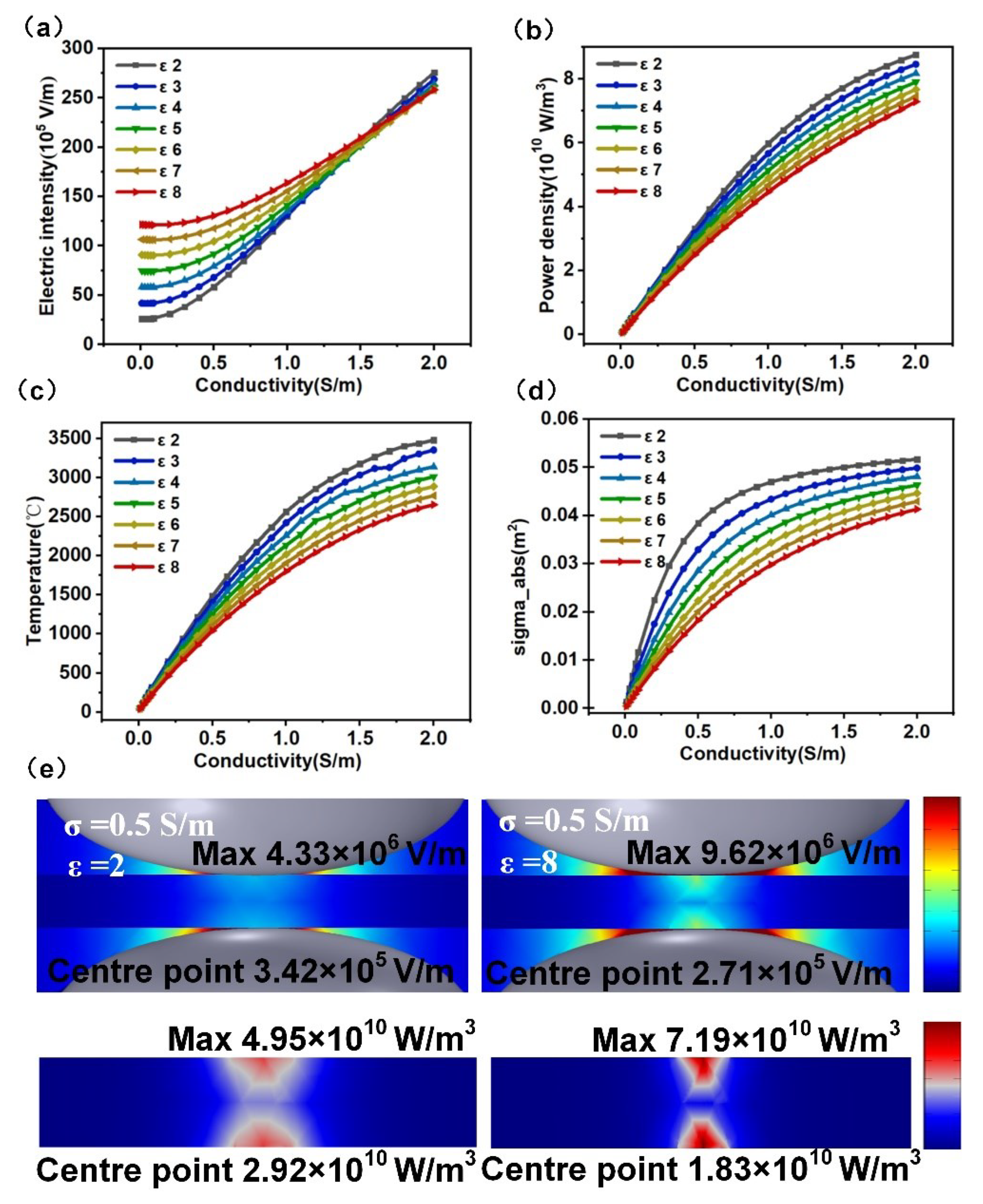
Figure 10 shows the effect of dielectric constant and conductivity of polymer on the strength of electric field. Figure 10a shows the change curve of maximum electric field strength in space with conductivity under different permittivity (real part). Figure 10b,c are the change curve of total power density and temperature of solder joint center with conductivity under different permittivity; Figure 10d is the change curve of absorption cross section of polymer with conductivity. It can be seen that polymers with different dielectric properties can also have a certain disturbance effect on microwave energy field in space, just like metal balls, and the increase of electrical conductivity and dielectric constant can significantly enhance the intensity of electric field in space. According to the variation trend of the total power density and temperature of the solder joint center with the conductivity and dielectric constant, combined with the absorption cross section of the polymer and the distribution diagram of the electric field intensity and power consumption density shown in Figure 10e, it can be concluded that the improvement of the conductivity and dielectric constant will improve the heating efficiency of the polymer, but also limit the transmittance of microwave energy. Therefore, according to the actual welding requirements, the dielectric properties of polymer should be controlled reasonably in industrial application, and the relationship between microwave loss and transmission of polymer should be balanced, so as to control the distribution of microwave energy and heat in polymer.

4.4. Exploration of PLFEMW Composite Welding Mode

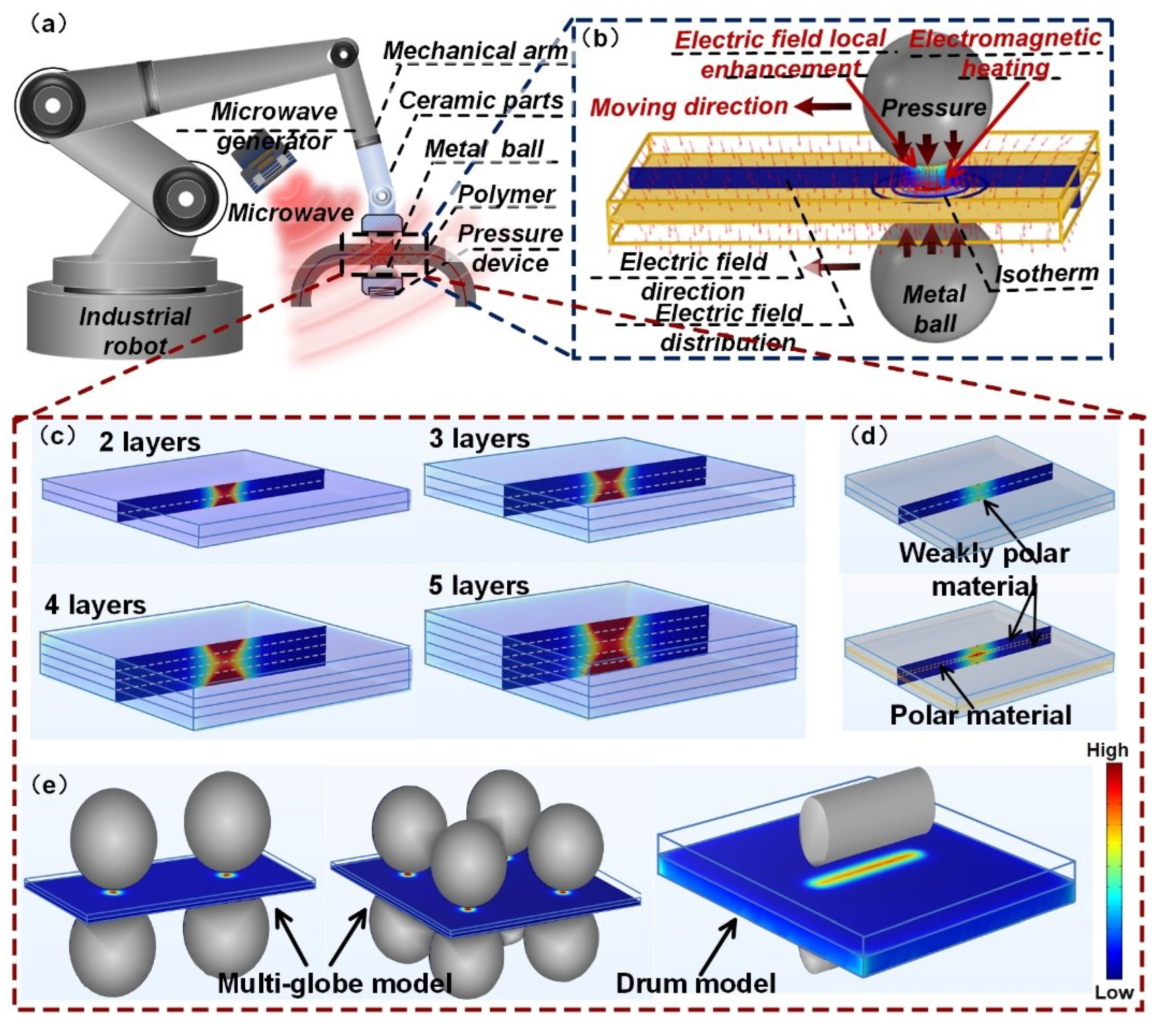
The PLFEMW welding method uses only a pair of simple metal spheres to excite microwave energy, the spheres also have the dual function of clamping the polymer, so they can replace traditional mechanical fixtures and be easily integrated with automated equipment. Figure 11a is a PLFEMW industrial welding robot designed based on PLFEMW welding method, and its working principle is shown in Figure 11b. The metal ball is driven by the robot arm to roll almost frictionless along the polymer surface to complete the welding work. Since the metal ball plays the dual role of "focusing" microwave and clamping polymer at the same time, The "focusing" position of microwave energy and the clamping position of welding materials are always synchronized in the welding process, which can not only take care of the welding quality, but also have certain welding flexibility, which can be used for welding three-dimensional complex samples.
High thickness welding of polymer and high efficiency welding of low dielectric loss materials put forward many technical requirements for traditional welding, but also greatly increased the energy consumption in the welding process. By virtue of the high penetration characteristics of microwave to dielectric materials, combined with the characteristics of PLFEMW method to enhance the local high strength of electric field, it can effectively solve the problems of high difficulty and high-power consumption in traditional welding. Figure 11c–e show the temperature distribution of welding models with different layers, composite welding models with non-polar substances, and multi-ball and roller welding models, respectively. It can be seen that, although the temperature difference between the polymer surface and the center of the solder joint increases significantly with the increase of polymer thickness, the center of the solder joint can still be heated to the melting temperature rapidly. By including strong polar polymer in the middle of non-polar or weak polar polymer, the target position can be heated and fused to achieve the purpose of welding. Based on this feature, it can be seen that the precise point heating inside the welding sample can be realized by the lap of polar polymer and non-polar polymer or by using polar polymer as the absorption layer. In addition, by combining this technology with automation technology, it can be convenient to realize the continuous welding of multiple points, lines and surfaces, and achieve the green welding requirements of high efficiency and low consumption.

5. Conclusions

This paper presents a novel and precise microwave welding method that utilizes the localized surface plasmon effect in metal macrogaps when exposed to microwave excitation. The proposed method successfully resolves the challenging issue of achieving accurate energy "focusing" during microwave welding. Through finite element numerical simulations of the electric and temperature fields, as well as welding tests conducted on PA66, the significant potential of the PLFEMW welding method in the field of clean microwave welding is demonstrated. The key contributions of this research can be summarized as follows:
(1)
This study has effectively developed and implemented a PLFEMW welding device, featuring a bimetallic ball that plays a dual role in both focusing microwave radiation and clamping the sample. This innovative design ensures that the heating and clamping sites remain fully synchronized during the entire welding process, thereby achieving optimal welding outcomes.
(2)
The localized surface plasmon effect of metal macro gaps has enabled precise focusing of microwave energy onto a considerably smaller area than its wavelength range. This capability allows for the precise and efficient heating of the polymer in the PLFEMW method, providing precision and accuracy.
(3)
The feasibility of PLFEMW processing has been successfully demonstrated through a welding experiment utilizing PA66. The welded joint exhibited a maximum tensile strength comparable to that of the base metal, accompanied by an aesthetically pleasing appearance and minimal material damage. These results demonstrate the great potential of PLFEMW as an efficient and reliable method for welding polymer materials.
(4)
By conducting finite element numerical simulations, this study investigated the primary process parameters that influence PLFEMW welding. The findings demonstrate that employing a rational process allocation strategy can effectively meet the demanding high-precision and low-energy welding requirements for various materials and complex shapes. These insights highlight the significant potential of PLFEMW welding technology in enabling efficient and accurate welding outcomes under diverse working conditions.

Acknowledgments

This work is supported by the National Natural Science Foundation of China (Grant No. 51901162). The authors thank the support of the Chinese National Talent Program.

References

  1. Acherjee, B. Laser transmission welding of polymers – A review on process fundamentals, material attributes, weldability, and welding techniques. J. Manuf. Process. 2020, 60, 227–246. [CrossRef]
  2. Acherjee, B., Mondal, S., Tudu, B., Misra, D. Application of artificial neural network for predicting weld quality in laser transmission welding of thermoplastics. Appl. Soft Comput. J. 2011, 11, 2548–2555. [CrossRef]
  3. Bank, M.S., Hansson, S. V. The Plastic Cycle: A Novel and Holistic Paradigm for the Anthropocene. Environ. Sci. Technol. 2019, 53, 7177–7179. [CrossRef] [PubMed]
  4. Bhattacharya, M., Basak, T. Susceptor-Assisted Enhanced Microwave Processing of Ceramics - A Review. Crit. Rev. Solid State Mater. Sci. 2017, 42, 433–469. [CrossRef]
  5. Bhudolia, S.K., Gohel, G., Leong, K.F. Advances in Ultrasonic Welding of Thermoplastic Composites : A Review. Materials 2020, 13, 1284. [CrossRef]
  6. Chen, B., Riche, C.T., Lehmann, M., Gupta, M. Responsive polymer welds via solution casting for stabilized self-assembly. ACS Appl. Mater. Interfaces 2012, 4, 6911–6916. [CrossRef]
  7. Chen, D., Wang, Y., Zhou, Helezi, Huang, Z., Zhang, Y., Guo, C.F., Zhou, Huamin. Current and Future Trends for Polymer Micro/Nanoprocessing in Industrial Applications. Adv. Mater. 2020, 2200903, 1–19. [CrossRef] [PubMed]
  8. Chen, Z., Huang, Y., Han, F., Tang, D. Numerical and experimental investigation on laser transmission welding of fiberglass-doped PP and ABS. J. Manuf. Process. 2018, 31, 1–8. [CrossRef]
  9. Cunha, M.A.G., Robbins, M.O. Effect of Flow-Induced Molecular Alignment on Welding and Strength of Polymer Interfaces. Macromolecules 2020, 53, 8417–8427. [CrossRef]
  10. El Khaled, D., Novas, N., Gazquez, J.A., Manzano-Agugliaro, F. Microwave dielectric heating: Applications on metals processing. Renew. Sustain. Energy Rev. 2018, 82, 2880–2892. [CrossRef]
  11. Gagliardi, F., Palaia, D., Ambrogio, G. Energy consumption and CO2 emissions of joining processes for manufacturing hybrid structures. J. Clean. Prod. 2019, 228, 425–436. [CrossRef]
  12. Green, M., Liu, Z., Xiang, P., Liu, Y., Zhou, M., Tan, X., Huang, F., Liu, L., Chen, X. Doped, conductive SiO2 nanoparticles for large microwave absorption. Light Sci. Appl. 2018, 7. [CrossRef] [PubMed]
  13. Hattermann, H., Bothner, D., Ley, L.Y., Ferdinand, B., Wiedmaier, D., Sárkány, L., Kleiner, R., Koelle, D., Fortágh, J. Coupling ultracold atoms to a superconducting coplanar waveguide resonator. Nat. Commun. 2018, 8. [CrossRef]
  14. Hill, J.M., Jennings, M.J. Formulation of model equations for heating by microwave radiation. Appl. Math. Model. 1993, 17, 369–379. [CrossRef]
  15. Huang, Y., Meng, X., Xie, Y., Wan, L., Lv, Z., Cao, J., Feng, J. Friction stir welding/processing of polymers and polymer matrix composites. Compos. Part A Appl. Sci. Manuf. 2018, 105, 235–257. [CrossRef]
  16. Jehanno, C., Alty, J.W., Roosen, M., De Meester, S., Dove, A.P., Chen, E.Y.X., Leibfarth, F.A., Sardon, H. Critical advances and future opportunities in upcycling commodity polymers. Nature 2022, 603, 803–814. [CrossRef]
  17. Jun, Y. seok, Habibpour, S., Hamidinejad, M., Park, M.G., Ahn, W., Yu, A., Park, C.B. Enhanced electrical and mechanical properties of graphene nano-ribbon/thermoplastic polyurethane composites. Carbon N. Y. 2021, 174, 305–316. [CrossRef]
  18. Lackinger, M., n.d. 50 Years Ago A tip for 2D polymer formation Fishing boats leave few safe havens for sharks 8–9.
  19. Lambiase, F., Genna, S. Homogenization of temperature distribution at metal-polymer interface during Laser Direct Joining. Opt. Laser Technol. 2020, 128, 106226. [CrossRef]
  20. Li, N., Li, Y., Zhou, J., He, Y., Hao, X. Drilling delamination and thermal damage of carbon nanotube/carbon fiber reinforced epoxy composites processed by microwave curing. Int. J. Mach. Tools Manuf. 2018, 97, 11–17. [CrossRef]
  21. Li, Y., Arinez, J., Liu, Z., Hwa Lee, T., Fan, H.T., Xiao, G., Banu, M., Jack Hu, S. Ultrasonic Welding of Carbon Fiber Reinforced Composite with Variable Blank Holding Force. J. Manuf. Sci. Eng. Trans. ASME 2018, 140, 1–11. [CrossRef]
  22. Li, Y., Hu, H., Jiang, W., Shi, J., Halas, N.J., Nordlander, P., Zhang, S., Xu, H. Duplicating plasmonic hotspots by matched nanoantenna pairs for remote nanogap enhanced spectroscopy. Nano Lett. 2020, 20, 3499–3505. [CrossRef] [PubMed]
  23. Li, Y., Xiong, M., He, Y., Xiong, J., Tian, X., Mativenga, P. Multi-objective optimization of laser welding process parameters: The trade-offs between energy consumption and welding quality. Opt. Laser Technol. 2022, 149, 107861. [CrossRef]
  24. Lutkenhaus, J. A radical advance for conducting polymers. Science 2018, 359, 1334–1335. [Google Scholar] [CrossRef] [PubMed]
  25. Majdzadeh-Ardakani, K., Banaszak Holl, M.M. Nanostructured materials for microwave receptors. Prog. Mater. Sci. 2017, 87, 221–245. [CrossRef]
  26. Mehra, N., Mu, L., Ji, T., Yang, X., Kong, J., Gu, J., Zhu, J. Thermal transport in polymeric materials and across composite interfaces. Appl. Mater. Today 2018, 12, 92–130. [CrossRef]
  27. Ni, J., Zhan, R., Qiu, J., Fan, J., Dong, B., Guo, Z. Multi-interfaced graphene aerogel/polydimethylsiloxane metacomposites with tunable electrical conductivity for enhanced electromagnetic interference shielding. J. Mater. Chem. C 2020, 8, 11748–11759. [CrossRef]
  28. Olofinjana, A., Yarlagadda, P.K.D.V., Oloyede, A. Microwave processing of adhesive joints using a temperature controlled feedback system. Int. J. Mach. Tools Manuf. 2001, 41, 209–225. [CrossRef]
  29. Park, M., Yoon, S., Park, J., Park, N.H., Ju, S.Y. Flavin Mononucleotide-Mediated Formation of Highly Electrically Conductive Hierarchical Monoclinic Multiwalled Carbon Nanotube-Polyamide 6 Nanocomposites. ACS Nano 2020, 14, 10655. [CrossRef]
  30. Pendry, J.B., Martín-Moreno, L., Garcia-Vidal, F.J. Mimicking surface plasmons with structured surfaces. Science 2004, 305, 847–848. [CrossRef]
  31. Potente, H., Karger, O., Fiegler, G. Laser and microwave welding - The applicability of new process principles. Macromol. Mater. Eng. 2002, 287, 743–744. [CrossRef]
  32. Qian, X.; Han, D.; Zheng, L.; Chen, J.; Tyagi, M.; Li, Q.; Du, F.; Zheng, S.; Huang, X.; Zhang, S.; et al. High-entropy polymer produces a giant electrocaloric effect at low fields. Nature 2021, 600, 664–669. [Google Scholar] [CrossRef] [PubMed]
  33. Rathinasuriyan, C., Pavithra, E., Sankar, R., Kumar, V.S.S. Current Status and Development of Submerged Friction Stir Welding: A Review. Int. J. Precis. Eng. Manuf. - Green Technol. 2021, 8, 687–701. [CrossRef]
  34. Ren, L., Zhang, K., Zhang, Y., Wang, F., Yang, F., Cheng, F. Mechanism of gas production under microwave/conventional pyrolysis of sewage sludge: Mechanism of microwave energy action on oxygen-containing functional groups. Chem. Eng. J. 2023, 464, 142511. [CrossRef]
  35. Ries, M., Possart, G., Steinmann, P., Pfaller, S. A coupled MD-FE methodology to characterize mechanical interphases in polymeric nanocomposites. Int. J. Mech. Sci. 2021, 204, 106564. [CrossRef]
  36. Robinson, J., Binner, E., Vallejo, D.B., Perez, N.D., Al Mughairi, K., Ryan, J., Shepherd, B., Adam, M., Budarin, V., Fan, J., Gronnow, M., Peneranda-Foix, F. Unravelling the mechanisms of microwave pyrolysis of biomass. Chem. Eng. J. 2022, 430, 132975. [CrossRef]
  37. Sahota, D.S., Bansal, A., Kumar, V. Application of microwave in welding of metallic materials - A review. Mater. Today Proc. 2020, 43, 466–470. [CrossRef]
  38. Schmailzl, A., Käsbauer, J., Martan, J., Honnerová, P., Schäfer, F., Fichtl, M., Lehrer, T., Tesař, J., Honner, M., Hierl, S. Measurement of core temperature through semi-transparent polyamide 6 using scanner-integrated pyrometer in laser welding. Int. J. Heat Mass Transf. 2020, 146. [CrossRef]
  39. Shao, Q., Wang, K.L. Heat-assisted microwave amplifier. Nat. Nanotechnol. 2019, 14, 9–11. [CrossRef]
  40. Sheikh-Ahmad, J.Y., Deveci, S., Almaskari, F., Rehman, R.U. Effect of process temperatures on material flow and weld quality in the friction stir welding of high density polyethylene. J. Mater. Res. Technol. 2022, 18, 1692–1703. [CrossRef]
  41. Song, R., Muliana, A., Rajagopal, K. A thermodynamically consistent model for viscoelastic polymers undergoing microstructural changes. Int. J. Eng. Sci. 2019, 142, 106–124. [CrossRef]
  42. Sun, Y., Sinev, I., Zalogina, A., Ageev, E., Shamkhi, H., Komissarenko, F., Morozov, I., Lepeshov, S., Milichko, V., Makarov, S., Mukhin, I., Zuev, D. Reconfigurable Near-field Enhancement with Hybrid Metal-Dielectric Oligomers. Laser Photonics Rev. 2019, 13, 1–6. [CrossRef]
  43. Sweeney, C.B., Burnette, M.L., Pospisil, M.J., Shah, S.A., Anas, M., Teipel, B.R., Zahner, B.S., Staack, D., Green, M.J. Dielectric Barrier Discharge Applicator for Heating Carbon Nanotube-Loaded Interfaces and Enhancing 3D-Printed Bond Strength. ACS Appl. Mater. Interfaces. 2020. [CrossRef] [PubMed]
  44. van Grootel, A., Chang, J., Wardle, B.L., Olivetti, E. Manufacturing variability drives significant environmental and economic impact: The case of carbon fiber reinforced polymer composites in the aerospace industry. J. Clean. Prod. 2020, 261, 121087. [CrossRef]
  45. Walker, S., Rothman, R. Life cycle assessment of bio-based and fossil-based plastic: A review. J. Clean. Prod. 2020, 261, 121158. [CrossRef]
  46. Wang, Chuanyang, Liu, H., Chen, Z., Zhao, D., Wang, Chengdong A new finite element model accounting for thermal contact conductance in laser transmission welding of thermoplastics. Infrared Phys. Technol. 2021, 112, 103598. [CrossRef]
  47. Xu, W., Zhang, L. Mechanics of fibre deformation and fracture in vibration-assisted cutting of unidirectional fibre-reinforced polymer composites. Int. J. Mach. Tools Manuf. 2016, 103, 40–52. [CrossRef]
  48. Yarlagadda, P.K.D.V., Chai, T.C. An investigation into welding of engineering thermoplastics using focused microwave energy. J. Mater. Process. Technol. 1998, 74, 199–212. [CrossRef]
  49. Yu, X.; Lyu, M.; Ou, X.; Liu, W.; Yang, X.; Ma, X.; Zhang, T.; Wang, L.; Zhang, Y.C.; Chen, S.; et al. AIEgens/Mitochondria Nanohybrids as Bioactive Microwave Sensitizers for Non-Thermal Microwave Cancer Therapy. Adv. Healthc. Mater. 2023, 2202907, 1–10. [Google Scholar] [CrossRef] [PubMed]
  50. Yussuf, A.A., Sbarski, I., Hayes, J.P., Solomon, M., Tran, N. Microwave welding of polymeric-microfluidic devices. J. Micromechanics Microengineering 2005, 15, 1692–1699. [CrossRef]
  51. Zeng, X., Cheng, X., Yu, R., Stucky, G.D. Electromagnetic microwave absorption theory and recent achievements in microwave absorbers. Carbon N. Y. 2020, 168, 606–623. [CrossRef]
  52. Zhu, J.B., Watson, E.M., Tang, J., Chen, E.Y.X.A synthetic polymer system with repeatable chemical recyclability. Science 2018, 360, 398–403. [CrossRef] [PubMed]
  53. Zhu, X. The Plastic Cycle – An Unknown Branch of the Carbon Cycle. Front. Mar. Sci. 2021, 7, 2019–2022. [Google Scholar] [CrossRef]
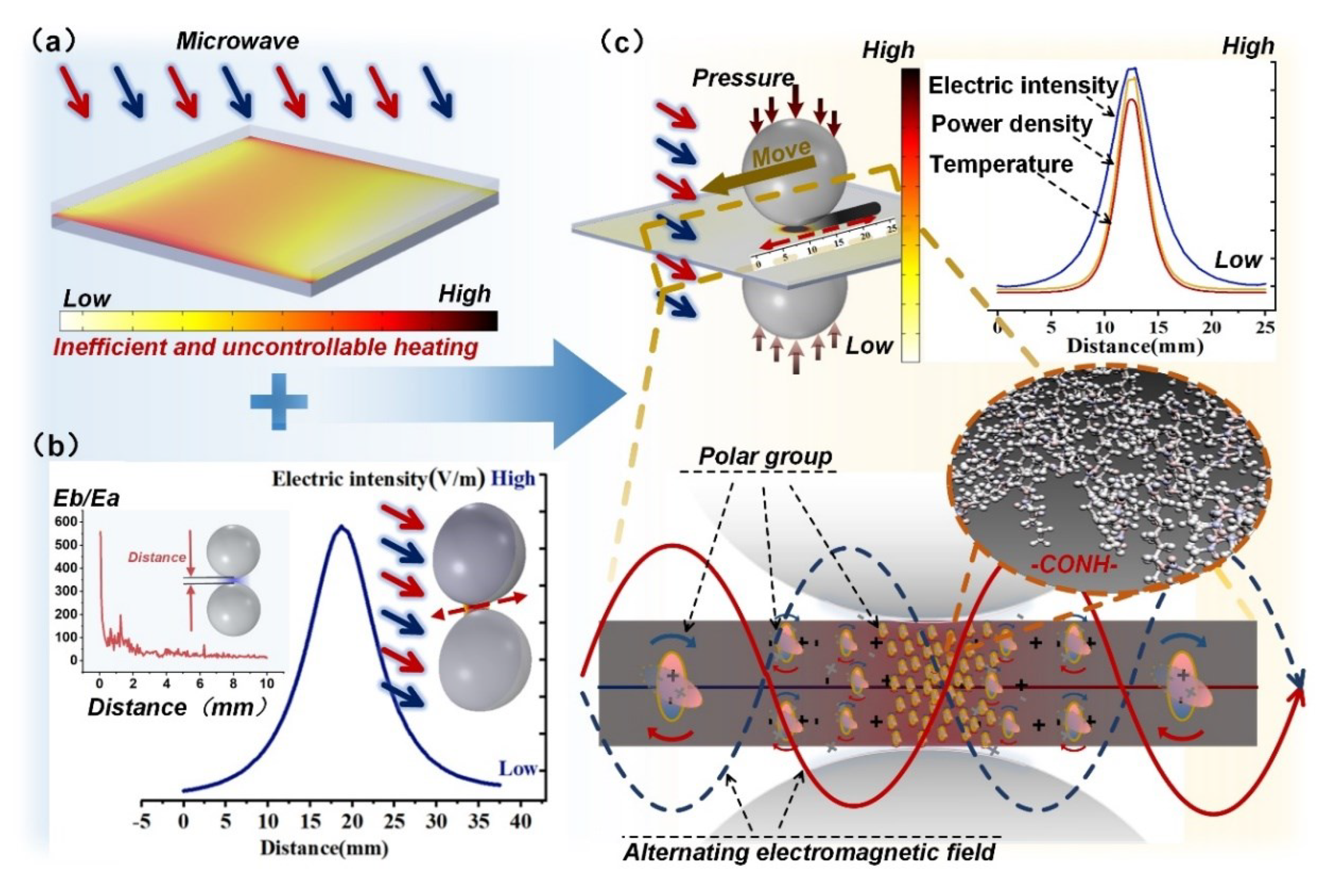
Figure 1. PLFEMW welding method. (a) Temperature distribution of traditional microwave heating processes. (b) Local “focusing” enhancement of microwave field excited by bimetallic spheres. (c) The schematic diagram of polymer precision welding based on the local "focusing" enhancement effect of microwave field excited by bimetallic ball includes the distribution curves of electric field, power density and temperature in weld zone and the schematic diagram of Electromagnetic-heating inside polymer.
Preprints 92870 g001
Figure 2. Electric field distribution under different modes of excitation with the same microwave energy. Among them, (a) traditional microwave heating mode, (b) local enhancement mode of bimetallic excited microwave field, and (c) local enhancement heating mode of bimetallic excited microwave field. (d) The electric field intensity distribution curve at the dotted line in Figure (a), (b) and (c) under different modes.
Preprints 92870 g002
Figure 3. (ac) respectively show the distribution of electric field, total power density and temperature inside the polymer. (d) is the distribution curve of electric field, power consumption density and temperature at the position of dotted line in Figure (ac).
Preprints 92870 g003
Figure 4. (a) Schematic diagram of PLFEMW welding process of PA66. (b) Electric field, total power consumption density and temperature distribution before and after adding glass film. (c) and (d) are the distribution of electric field and temperature field in the depth direction of solder joint inside the polymer.
Preprints 92870 g004
Figure 5. (a) shows the temperature distribution of polymer cross sections under different curvature radii. (b,c) are temperature distribution curves of solder joint depth and width under different curvature radius conditions.
Preprints 92870 g005
Figure 6. (a) Temperature rise curves of PA66 welding process under different curvature radii. (b) Temperature distribution of PA66 welding process under different curvature radius conditions.
Preprints 92870 g006
Figure 7. Mechanical properties of different PLFEMW samples. (a) Force-displacement curves of base material and different specimens. (b) Morphology of base material and different specimens after tensile fracture. (c) Fracture morphology of 27.5mm sample. (d) Local magnification of the fracture.
Preprints 92870 g007
Figure 8. Influence characteristics of ball material, gap size and size on electric field strength. (a) the curve of the maximum electric field intensity with the conductivity of the ball under different dielectric constants. (b) When the radius of metal sphere is 12.5 mm, the electric field intensity changes with the distance between two metal spheres. (c) When the distance between the two metal spheres is 2 mm, the variation curve of the electric field intensity with the curvature radius of the metal sphere. (d) When the curvature radius of the metal ball is 5mm, 15 mm, 25 mm and 35mm, the electric field intensity distribution curve on the dotted line is shown in the figure.
Preprints 92870 g008
Figure 9. Effect of electromagnetic wave wavelength and incidence Angle on electric field intensity. (a) Variation curve of electric field intensity with wavelength. (b) Variation curve of maximum electric field intensity with incidence elevation under different incident azimuth conditions.
Preprints 92870 g009
Figure 10. Effect of permittivity and conductivity of polymer on electric field strength. (a) Curve of maximum electric field intensity with polymer conductivity under different dielectric constants. (b,c) Change curves of electric field intensity and temperature at the center of solder joint with conductivity under different dielectric constants. (d) Curve of absorption cross section of polymer with conductivity under different dielectric constant conditions. (e) electric field intensity and power consumption density distribution for ε = 0.5 S /m, ε =2 and ε =8 conditions.
Preprints 92870 g010
Figure 11. (a) Schematic diagram of PLFEMW industrial welding robot and (b) schematic diagram of machining principle. (ce) respectively show the temperature distribution of multi-layer welding model, composite welding model and multi-ball and roller welding model.
Preprints 92870 g011
Table 1. Parameters of PA66, metal ball and glass.
Thermal Conductivity
W/(m·K)
Density

Kg·m-3
Constant Pressure Heat Capacity
J/(kg·K)
Relative Permeability
1
Conductivity
S·m-1
Relative Permittivity
1
PA66 0.3 1150 1700 1 0.4 4.5-0.056j
Metal ball 44.5 7850 475 1 4.032×10⁶ piecewise
Glass 1.4 2210 730 1 41×10-14 2.55
Disclaimer/Publisher’s Note: The statements, opinions and data contained in all publications are solely those of the individual author(s) and contributor(s) and not of MDPI and/or the editor(s). MDPI and/or the editor(s) disclaim responsibility for any injury to people or property resulting from any ideas, methods, instructions or products referred to in the content.
Copyright: This open access article is published under a Creative Commons CC BY 4.0 license, which permit the free download, distribution, and reuse, provided that the author and preprint are cited in any reuse.
Prerpints.org logo

Preprints.org is a free preprint server supported by MDPI in Basel, Switzerland.

Subscribe

© 2024 MDPI (Basel, Switzerland) unless otherwise stated