1. Introduction
Microwave radio astronomy has been actively developing since the 60s (an overview of this stage of development is presented, for example, in [1]). The first large antennas of this range were built, for example, the 11-meter radio telescope of the NRAO USA, RT-22 FIAN, RT-22 KrAO, etc. Quite sensitive uncooled detectors have been created, followed by cryogenic detectors (as an example, let us cite such leading concepts as a Transition Edge Sensor (TES) [2,3] and Kinetic Inductance Detectors (KID) [4,5]. In subsequent years, impressive progress was observed in improving the reception technology of millimeter waves, stimulated to a large extent precisely by the needs of radio astronomy. The noise temperature of receiving systems — the main parameter that characterizing their sensitivity — has decreased by about 2 orders of magnitude since the late 60s and has come close to the so-called quantum limit. Many new radio telescopes of this range were built, including several antenna arrays.
Currently, there are many important astrophysical problems that can be solved by millimeter (MM) and subMM astronomy [6,7,8]. Many of them are related to the study of the “cold” Universe. These are mainly dense interstellar gas-dust clouds, both in our Galaxy and in distant objects. They are interesting, first of all, because the process of star formation takes place in them, many aspects of which are still not fully understood. The temperature of these clouds is from several to tens of Kelvins. The peak of their emission at this temperature is in the MM-subMM range. This range is also extremely rich in spectral lines, mainly corresponding to transition between rotational levels of molecules with relatively low excitation energy. A lot of various molecules have been found in interstellar clouds. In addition, lines are observed that arise during transitions between levels of the fine structure of some atoms and ions. Observations of spectral lines make it possible to study the physical conditions and processes in interstellar clouds, as well as their chemical composition. In addition, the heating of dust and gas is carried out by ultraviolet radiation from stars and other factors related ultimately to the processes of energy release in protostars and young stars. It is important that interstellar clouds are practically transparent for MM and subMM waves, in contrast to the optical range, where absorption can reach 100m or more. Thus, observations in this range represent a unique tool for studying the inner regions of dense interstellar clouds, which are the “cradles” of new stars and are inaccessible to other methods of astronomical research. Studies of the formation of stars and galaxies are one of the main incentives for the development of millimeter and submillimeter astronomy. The “cold” objects of study also include the microwave “relict” background, the peak intensity of which falls in the millimeter range.
Along with the study of the cold Universe, MM and subMM, astronomy makes an invaluable contribution to the study of objects characterized by extremely high energy release – such as active galactic nuclei, which, apparently, are accreting supermassive black holes. It is in this range that it is possible to realize the required ultra-high angular resolution, as well as reduce the influence of scattering effects along the line of sight.
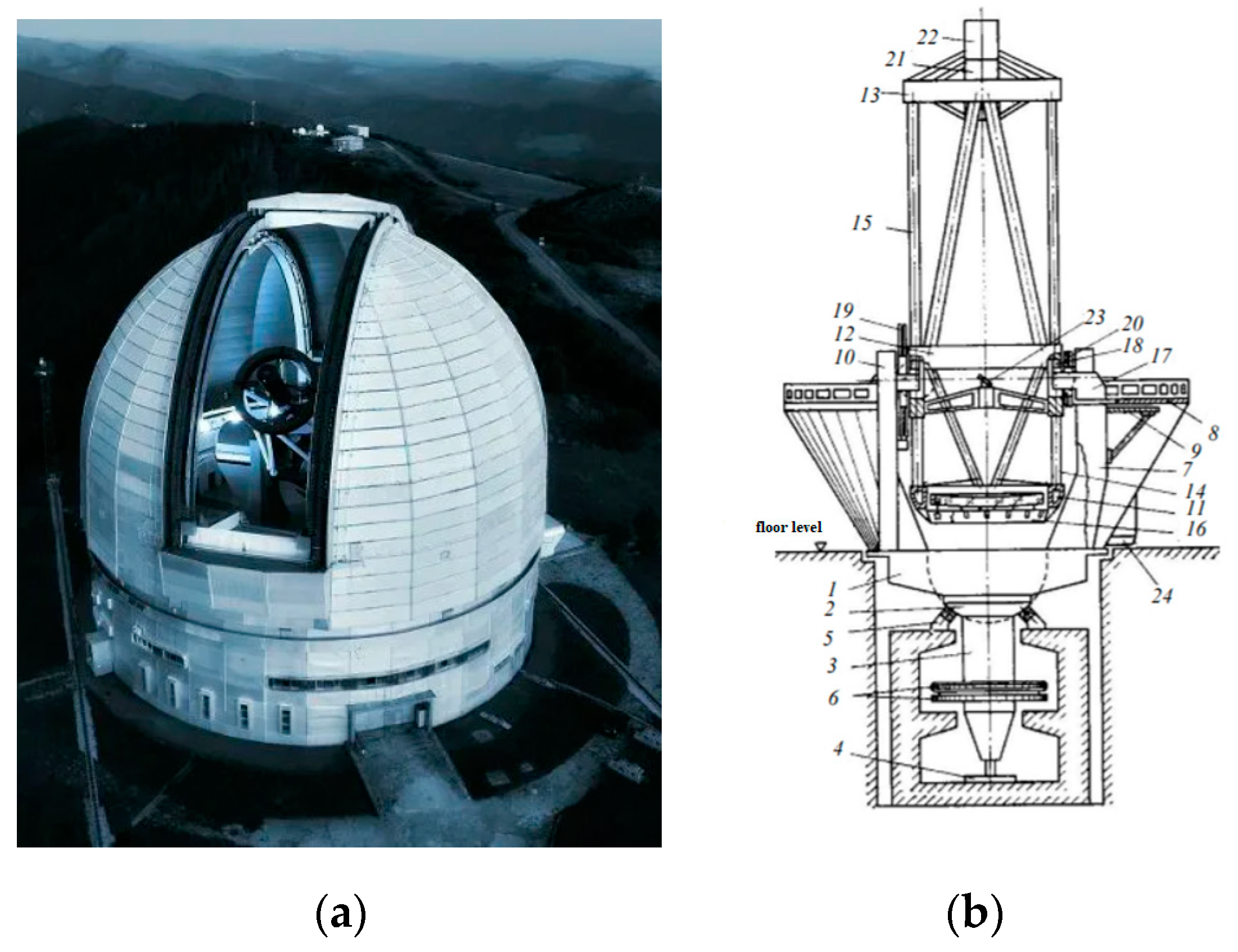
In Russia, there are practically no tools for effective observations in the short-wave part of MM and in the subMM wavelength ranges. Of the antennas available in Russia, only RT-13 IPA RAS [9] have a surface accuracy sufficient for effective operation at wavelengths of ~1 mm. The quality of the 7.5 m antennas of the Bauman Moscow State Technical University in Dmitrov is positioned slightly worse [10]. However, the astroclimate in their locations will most likely not allow them to be used any effectively at wavelengths shorter than ~2 mm. Russia’s entry into the European Southern Observatory could partially correct the situation, however, despite many years of efforts in this direction, the prospects for this remain very vague, and over the past year they seem to have been completely lost for a long time. Among the ground-based instruments being designed with Russian participation, the central place is occupied by the International Russian-Uzbek megaproject “Suffa” for the construction of an observatory [11] on the Suffa plateau in Uzbekistan. The BTA optical telescope (Big Telescope Alt-Azimuth, (see
Figure 1) in the SAO RAS [12] may well be used for working out the techniques and receiving devices of this range (as well as a number of urgent tasks of modern MM and subMM astronomy). The surface quality of the optical telescope mirror will certainly (by two orders of magnitude) satisfy the requirements for research in the subterahertz range. Observations in the MM and subMM ranges can be carried out in the early morning or late evening, in contrast to observations in the optical range, which are carried out only at night in the absence of background illumination of the sky.
Potentially, daylight time, which is not used for optical observations, is also quite suitable for MM observations, but opening the visor of the telescope dome in the daylight time, as a rule, is not allowed from the point of view of thermalization of the mirror and the dome space, which is actively stabilized for night mode. In the afternoon, after sunrise, dramatic thermal processes are possible, calling into question the success of thermalization in the evening, which will negatively affect the quality of subsequent night optical observations. Thus, expanding the functionality of the telescope into the MM region is some addition to the functionality and the main observation program and does not interfere with it, unless the dome is opened significantly beyond the twilight period. This is an absolute advantage of the proposed scheme for supplementing the BTA with a MM receiver.
2. Astroclimate Conditions at the BTA Site of the SAO RAS
To select the frequency range of the receiving system, it is necessary to assess the astroclimate conditions in the windows of atmospheric transparency. An active study of the astroclimate in the vicinity of the BTA was carried out with the participation of the authors of the article; a review of the results of astroclimate measurements at various sites is given in [13].
To monitor the transparency of the atmosphere, the MIAP-2 device (a two-channel microwave atmospheric absorption meter) was used, [14],
Figure 2. In detail, the methodology for processing measured data is given in the publication [15].
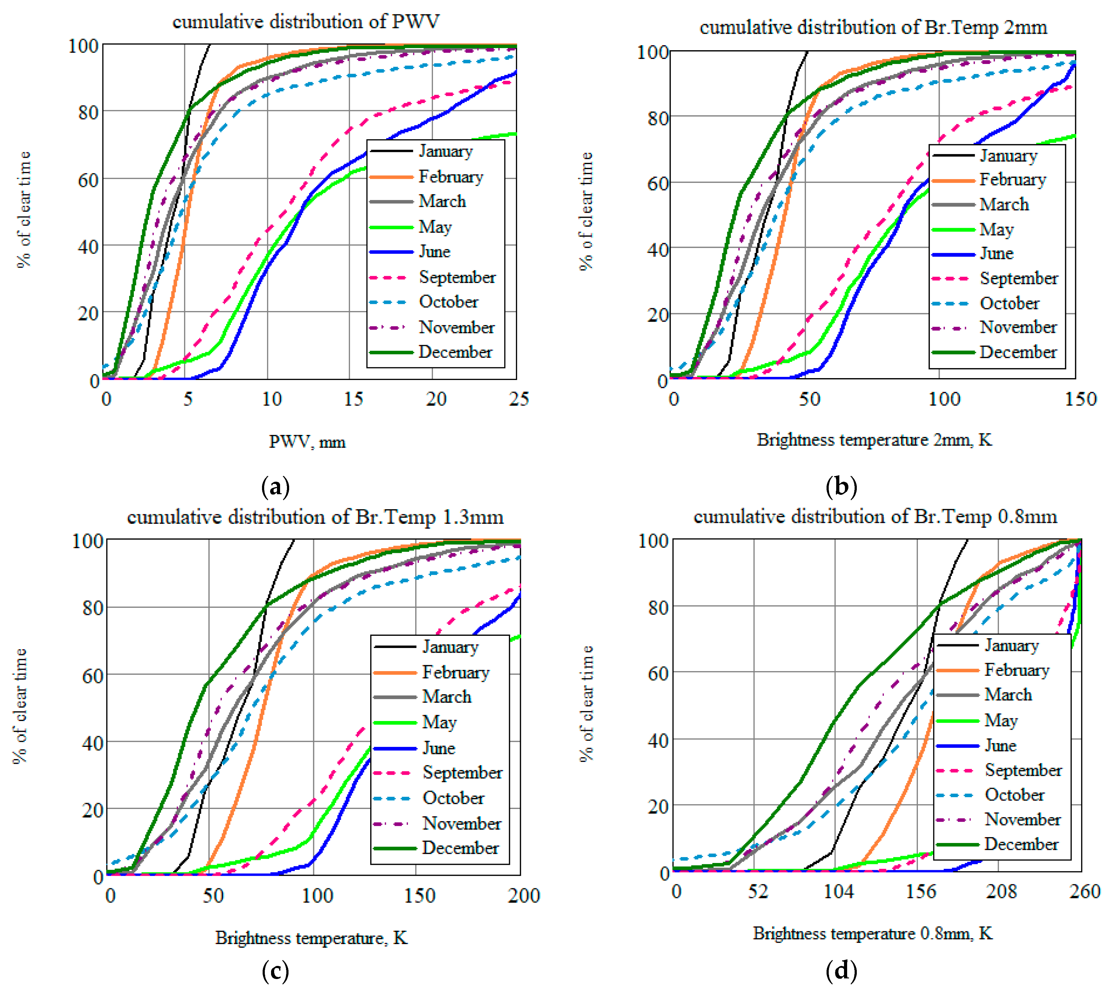
Cumulative distributions of brightness temperature for transparency windows of 3, 2, 1.3 and 0.8 mm from the work [16] are shown in
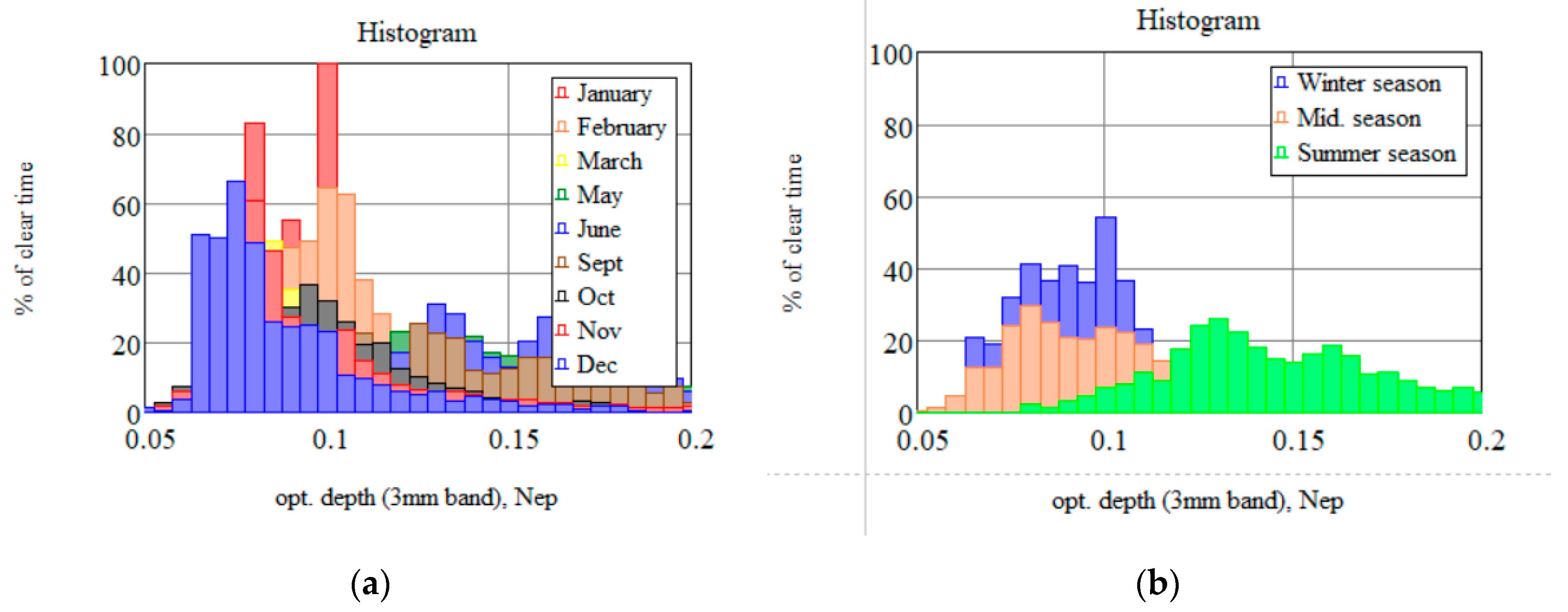
Figure 3, histograms by month and season in
Figure 4.
The key conclusion from long-term cycles of observations of the microwave astroclimate directly from the BTA telescope (photo of the device on the window, Fig. 2b) is the following: observations in the (~100 and ~150 GHz) transparency windows undoubtedly do not have significant atmospheric restrictions, observations in the transparency window of ~230 GHz require the selection of certain periods of time; clear, frosty winter days are quite suitable. The use of the BTA in subsequent (350 GHz and higher) windows of atmospheric transparency is practically unpromising due to the high humidity of the atmosphere and the insufficiently high altitude of the telescope above sea level.
2. Receiving System for the BTA
Despite the extensive list of current astronomical tasks in the MM frequency range, there are various limitations on a ready-made instrument (especially for the BTA designed for the optical range). Therefore, in this section, a preliminary assessment will be made of the possibilities of creating and mounting a MM receiver on the site of the BTA telescope, and then, based on the results obtained, a set of relevant astronomical problems proposed for research based on the optical telescope will be considered.
Initially, it is proposed to study the surface of the telescope mirror (see
Section 3.1). If the surface quality (roughness value) of the optical mirror certainly meets the requirements of the MM range, then the aluminum coating (its thickness is less than the skin layer in this wavelength) requires additional research.
Another issue is the proposed location of the receiving system and the estimation of the width of the Gaussian beam (detailed in
Section 3.2). As can be seen from
Figure 1, there are three possible locations for the detection module: primary focus and I or II Nasmith focus. Setting to primary focus is impossible, because this will interfere with the telescope’s main program. However, installing a cooled receiver in the Nasmith II or I circuit is a real possibility.
From October 23 to October 29, 2019, an expedition was conducted to the Special Astrophysical Observatory of the Russian Academy of Sciences to discuss the collaboration on the installation of a MM receiving system. Some photographs are shown in
Figure 5.
3.1. Surface of the BTA’s Mirror
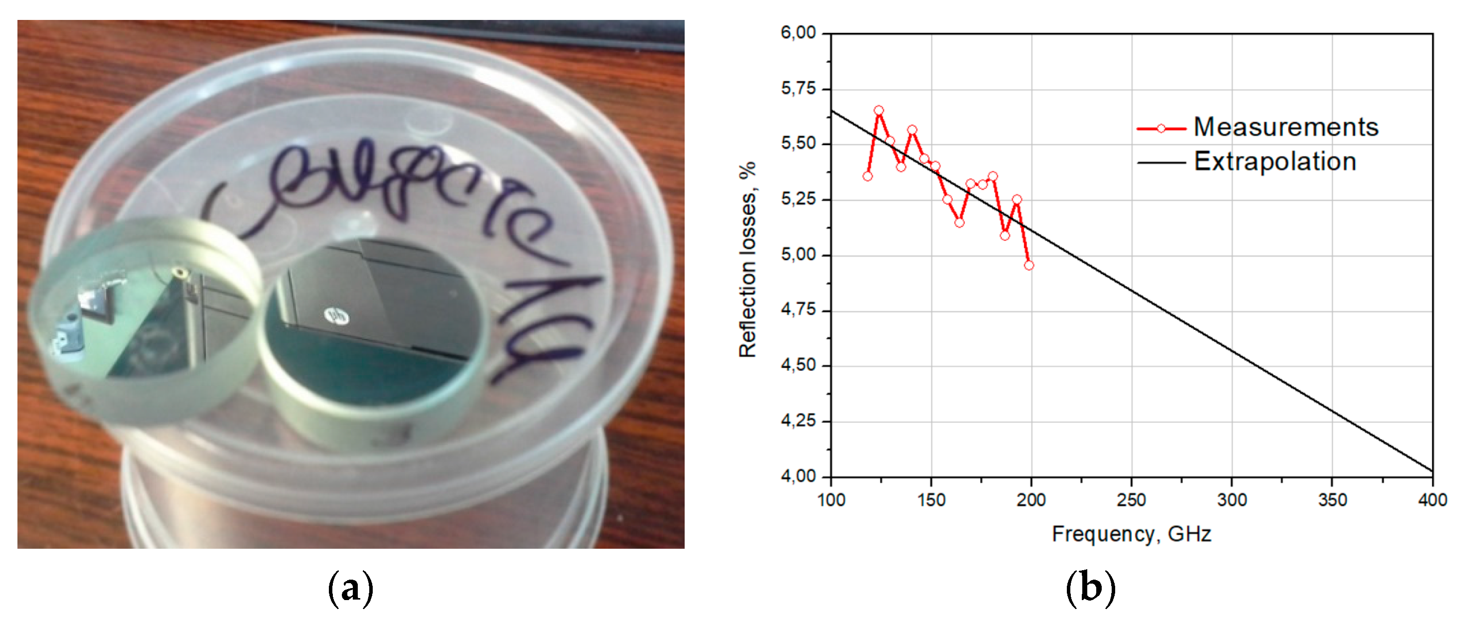
The mirror of the BTA telescope is a monolithic glass with a diameter of 605 cm with an aluminum coating of ~100 nm and a weight of about 42 tons. In 2018, the surface of the telescope’s main mirror was replaced (redeposition) [17]. A special vacuum equipment located inside the observatory is used to cover the surface of the mirror with aluminum. In the process of deposition of the main mirror, special “witness” samples were made — test samples that were deposited in the same vacuum cycle with the main mirror. They are necessary for studying the characteristics of the mirror surface. Experimental studies of the reflection losses of two samples of “witnesses” were conducted on the basis of the IAP RAS (
Figure 6). The sample (
Figure 6a) is a polished glass disk with a diameter of 30 mm with a 100 nm thick aluminum film deposited on it. Reflectivity measurements were carried out in a cryovacuum resonator complex [18]. The experimental stand from [18] is based on a high-quality (Q~106) Fabry-Perot resonator, which is located in a vacuum chamber. A symmetrical resonator is used as a reference, and a test sample of the reflector is installed on a flat copper mirror of an asymmetric resonator. Reflection losses from samples at normal radiation incidence are determined based on the results of measurements of the resonator response width.
According to the measurement results (
Figure 6b), it can be seen that the measured reflection loss is 5-6% in the frequency range 120-200 GHz at room temperature. The efficiency of the mirror as a MM and subMM wave reflector (better than 94%) is no worse than the measured reflection coefficient in the “native” optical range (400-1200 nm [
Figure 2 and
Figure 3 in [17]]).
3.2. The Nasmith System of the BTA Telescope
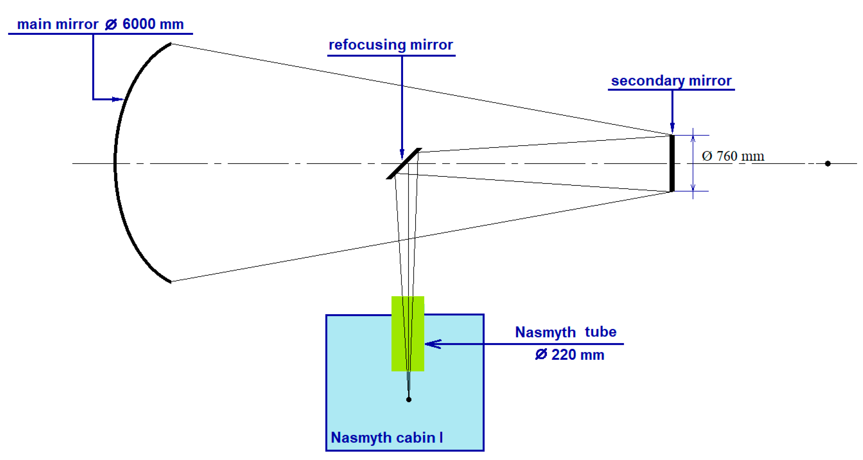
A schematic representation of the Nasmith I system of the BTA telescope is shown in
Figure 7. The signal from the main mirror gets to the secondary mirror, and then to the focusing, deflecting beam mirror to the first or second Nasmith focus of the telescope. Two methods for calculating the width of the Gaussian beam will be considered: quasi-optical and using standard software for optical calculations Zemax OpticStudio.
Quasi-Optical Calculation Method
The calculation method is given in detail in [19].
Calculation of the Gaussian beam radius in the Nasmith 1 scheme of the BTA telescope
The matrix of propagation of a Gaussian beam through two free spaces and a mirror:
L1 is the distance from the aperture of the horn to the refocusing mirror
Fmirr is the focal length of the focusing mirror
L2 is the effective focal length of the main mirror
where
is an auxiliary coefficient (
ws is the radius of the Gaussian beam on the secondary mirror,
ha is the size of the aperture of the horn,
k is the Gaussian coefficient).
hf is the magnitude of the curvature of the phase front after the horn (∞).
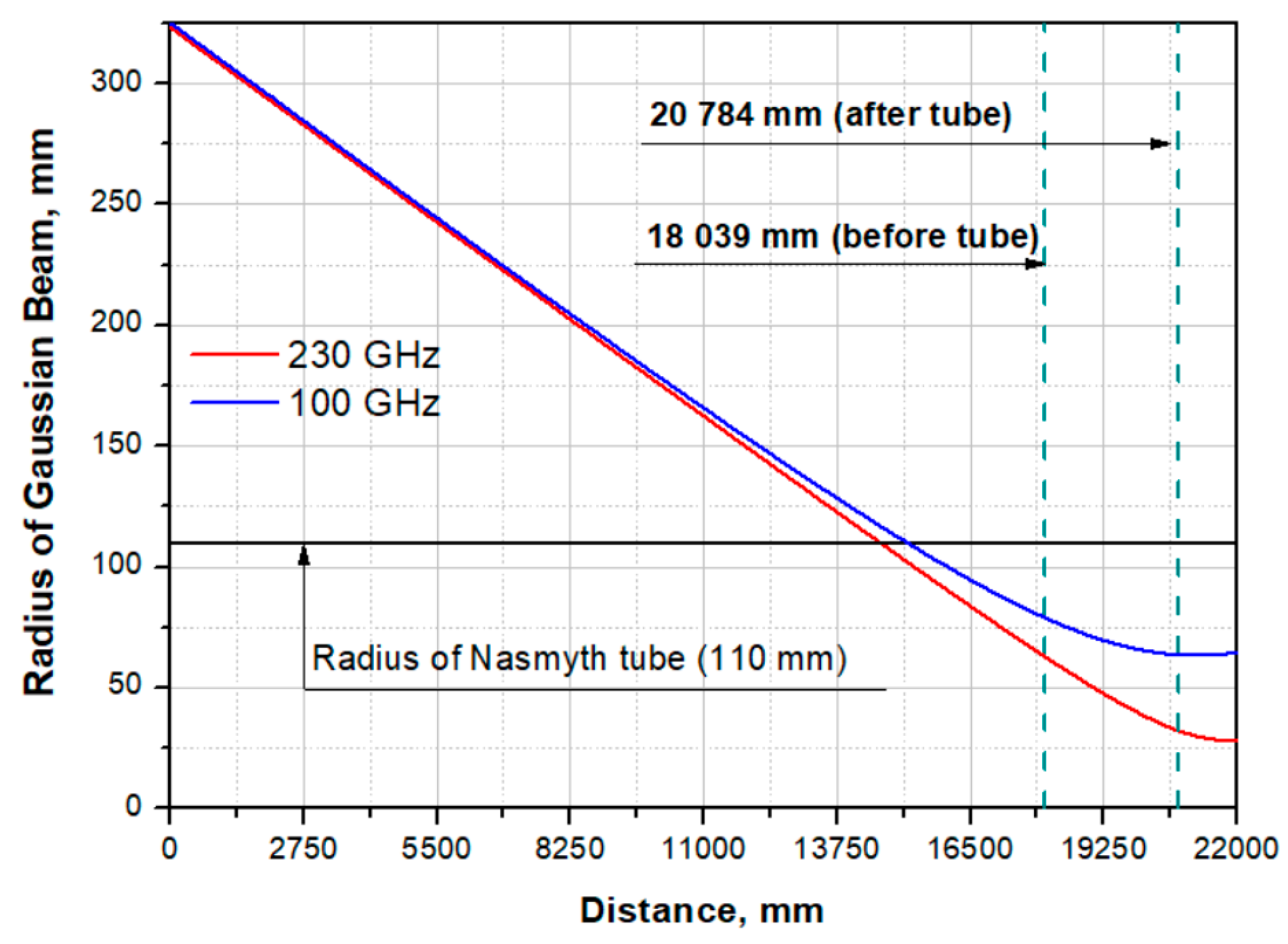
The radius of the Gaussian beam during propagation in the Nasmith I system of the BTA telescope:
z is the Gaussian beam propagation distance (from 0 to 22014 mm).
Losses during Propagation of a Gaussian Beam Through the “Tube”
When propagating a Gaussian beam in the Nasmith I scheme, for determining of the losses when passing through the “Nasmith tube”, it is necessary to consider the truncation of the beam and the following formula can be used [19]:
where
rt is the radius of the beam truncation (in our case it is equal to the radius of the pipe – 110 mm). Accordingly, the share of passing power in % is (1 –
fout)*100.
Calculation in Zemax OpticStudio
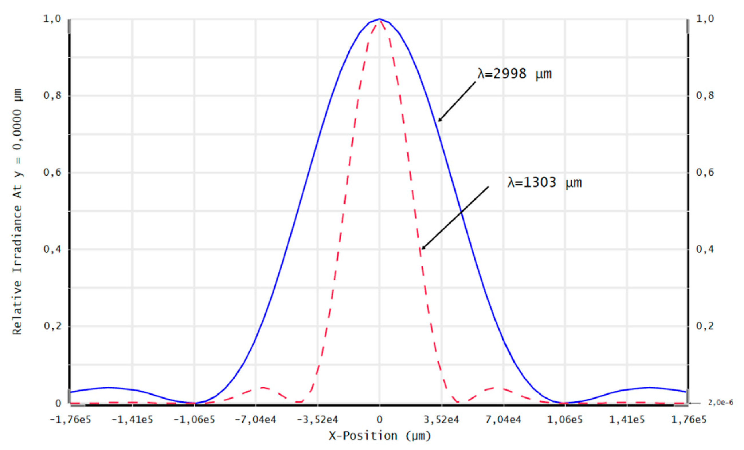
Standard software for optical calculations Zemax OpticStudio was also used to estimate the beam size in the Nasmith focus of the BTA telescope. Despite the fact that the operating spectral range of the detector goes beyond the limits of the optical radiation range, the analysis of the diffraction image diameter can be performed using the wave effect analysis tools in Zemax OpticStudio (PSF, MTF, etc.), [20,21].
Figure 9 shows graphs of Huygens PSF scattering spots in the XY plane at the Nasmith focus for the wavelengths λ=1303 µm (230 GHz) and λ=2998 µm (100 GHz). The Huygens PSF method was used as more accurate because it takes into account the discrepancy between the position of the planes of the geometric focus and the image of the optical system. Diameter of the first diffraction maximum at λ=1303 µm (230 GHz) made up D(λ=1303 µm)1-st dif.max.≈ 88 mm, at λ=2998 µm (230 GHz) D(λ=2998 µm)1-st dif.max. ≈ 200 mm. The results of estimating the Gaussian beam radius in Zemax OpticStudio using the “Gaussian paraxial beam” with a Gaussian beam apodization coefficient k = 0.644 are presented in
Table 1
This section provides information only to determine the possibility of a Gaussian beam passing into the Nasmith I focus of the BTA telescope and the need to create corrective elements before arriving at the Nasmith tube at frequencies of 90 and 230 GHz (as shown in the calculations above, it is not required, which greatly simplifies the problem since corrective elements will only be required after passing through the Nasmith tube). For more detailed calculations and calculations of additional elements for supplying a signal to the detecting device, it is necessary to clarify the following points:
selection of an astronomical task (depending on this, the central frequency of the signal and the reception bandwidth will be determined, as well as the choice of matching horn, lens, mirror or horn-lens (mirror) structures);
selection of a cryogenic system and determination of its exact overall dimensions (depending on the size and location of the cryostat system, additional mirrors for “transferring” the signal to the cryostat window will be calculated);
determination of the maximum permissible diameter of the window in the cryostat through which the signal will be supplied to the detecting device (depending on this size, corrective elements for beam narrowing will be modeled).
Since the maximum diameter of the cryostat window is significantly smaller than the beam diameter in the Nasmith focus, it is planned to use a matching optical system of off-axis parabolic mirrors for scaling of the output numerical aperture of the telescope. The relative aperture of the telescope in the Nasmith focus is 1/30 (F#=30), which corresponds to the diameter of the first diffraction maximum for λ=2998 μm D1-st dif.max. ≈ 200 mm. Preliminary calculations of the matching optics showed that the optimal diameter of the horn is 20 mm. Hence the linear magnification of the optical system of two paraboloids is V=. The main limitation on the maximum achievable increase in matching optics are the dimensions of the Nasmith platform and the design features of the receiver. The image size depends on the ratio of the focal lengths of the paraboloids. An increase in the focal length of the first paraboloid will lead to an increase in the diameter of the collimated beam and the length of the system; a decrease in the focal length of the second paraboloid will lead to a decrease in the rear segment of the system, which will not allow the cryostat horn to be placed in the correct position.
3.3. Cryogenic System
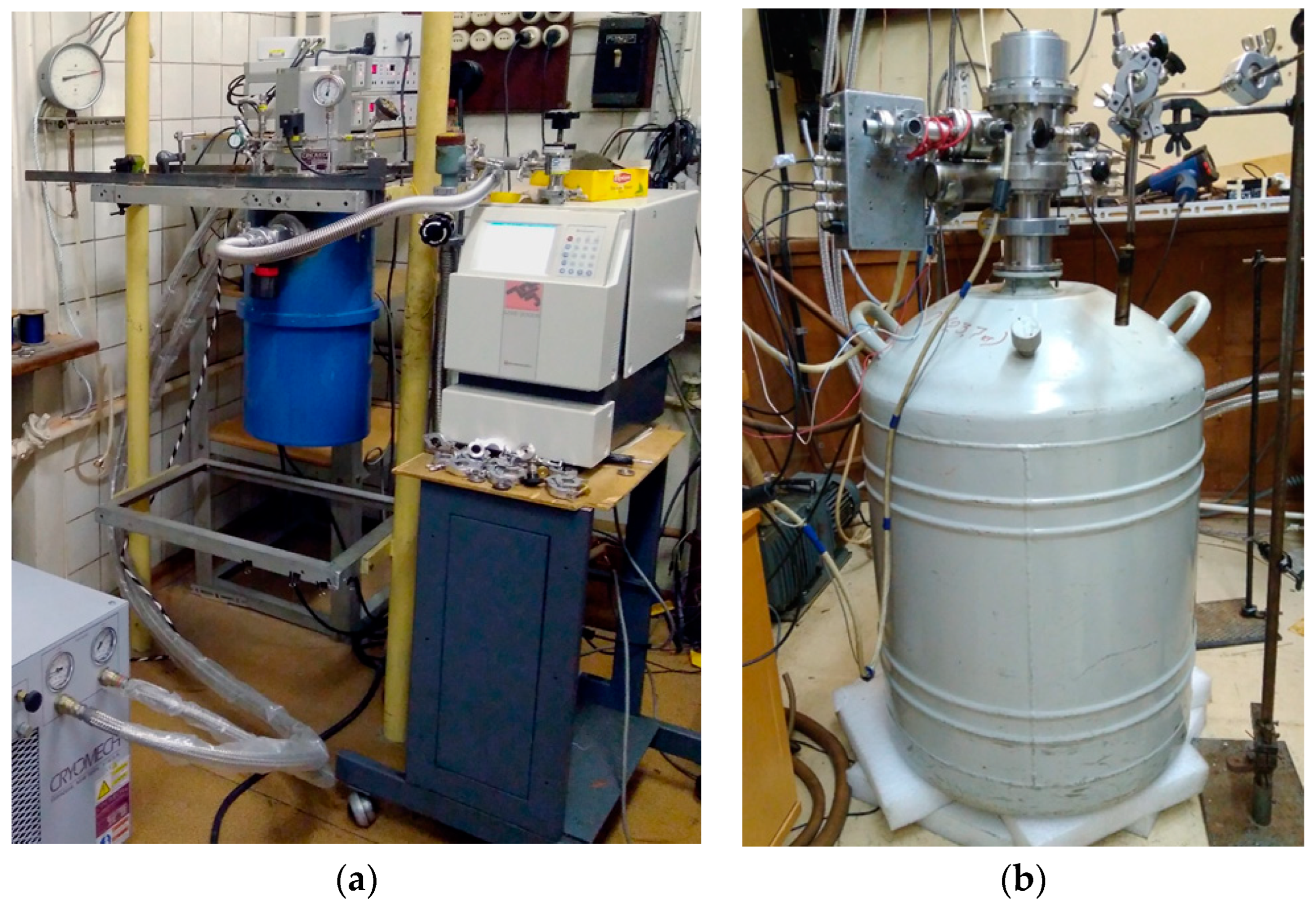
Initially, two options were considered as a cryostat system
Figure 10: a system based on pulse tubes and a filler cryostat-insert, on which experimental studies of the developed samples were carried out (these cryosystem are used to conduct experimental samples of detecting arrays based on SINIS detectors in the laboratory).
1. Cryostat with pumping out liquid helium vapor 3He Heliox AC-V (
Figure 10a). The achievable minimum operating temperature is 273 mK. The advantages of such cryogenic system include the following: the presence of a closed–cycle cryocooler on pulse tubes, i.e. there is no need to pour liquid helium (but this is also the disadvantage of such a system – the presence of “parasitic” noise from the pulsation system), a large volume for mounting samples (the pad diameter is 147 mm, the height is 100 mm), high operating temperature stability (± 3 mK at temperatures below 2 K).
2. Filler cryostat-insert (
Figure 10b) that was developed at the P.L. Kapitsa Institute of Physical Problems of the Russian Academy of Sciences [22]. The minimum achievable operating temperature is 80 mK. In addition to achieving an ultra-low temperature, such a cryostat does not require external pumps, which significantly reduces vibration noise and interference (which increases the sensitivity of the entire receiving system), however, this requires pouring liquid helium and the cycle of continuous operation at a temperature of 0.1 K is quite short.
Both options can be used depending on the chosen task for research at the BTA telescope.
Currently, in connection with receiving funding under the Russian Science Foundation project No. 23-62-10013 “Development of a prototype of a domestic subterahertz observatory as part of an optical telescope,” various options for creating various cryosystems are being considered. The details of these proposals are given in publication [23] in Section 3.4.
3.4. Detecting Device
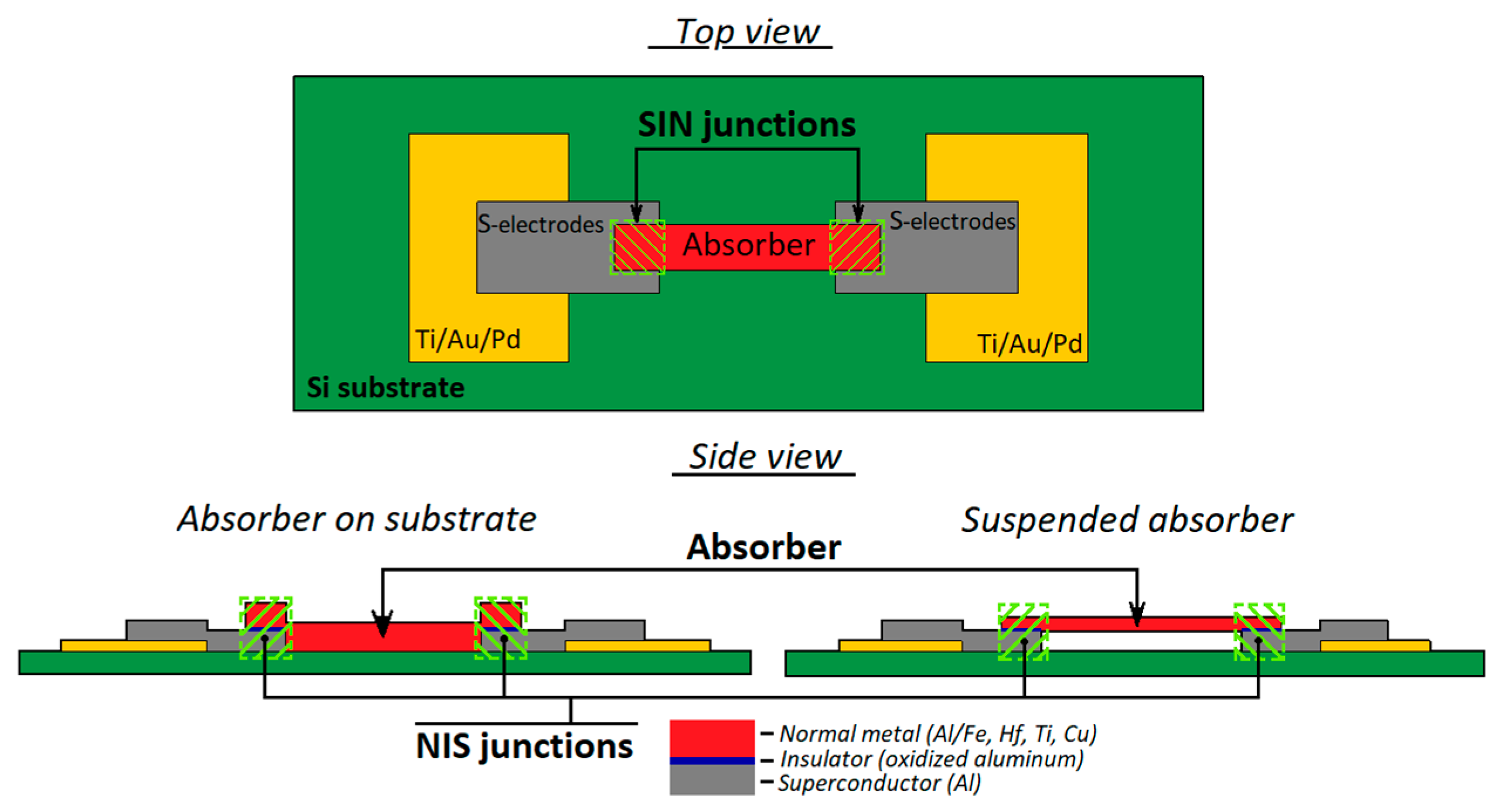
As a high sensitive receiving device, the implementation of a receiving cell based on detectors of the superconductor-insulator-normal metal-insulator-superconductor structure is proposed (a schematic image is shown in
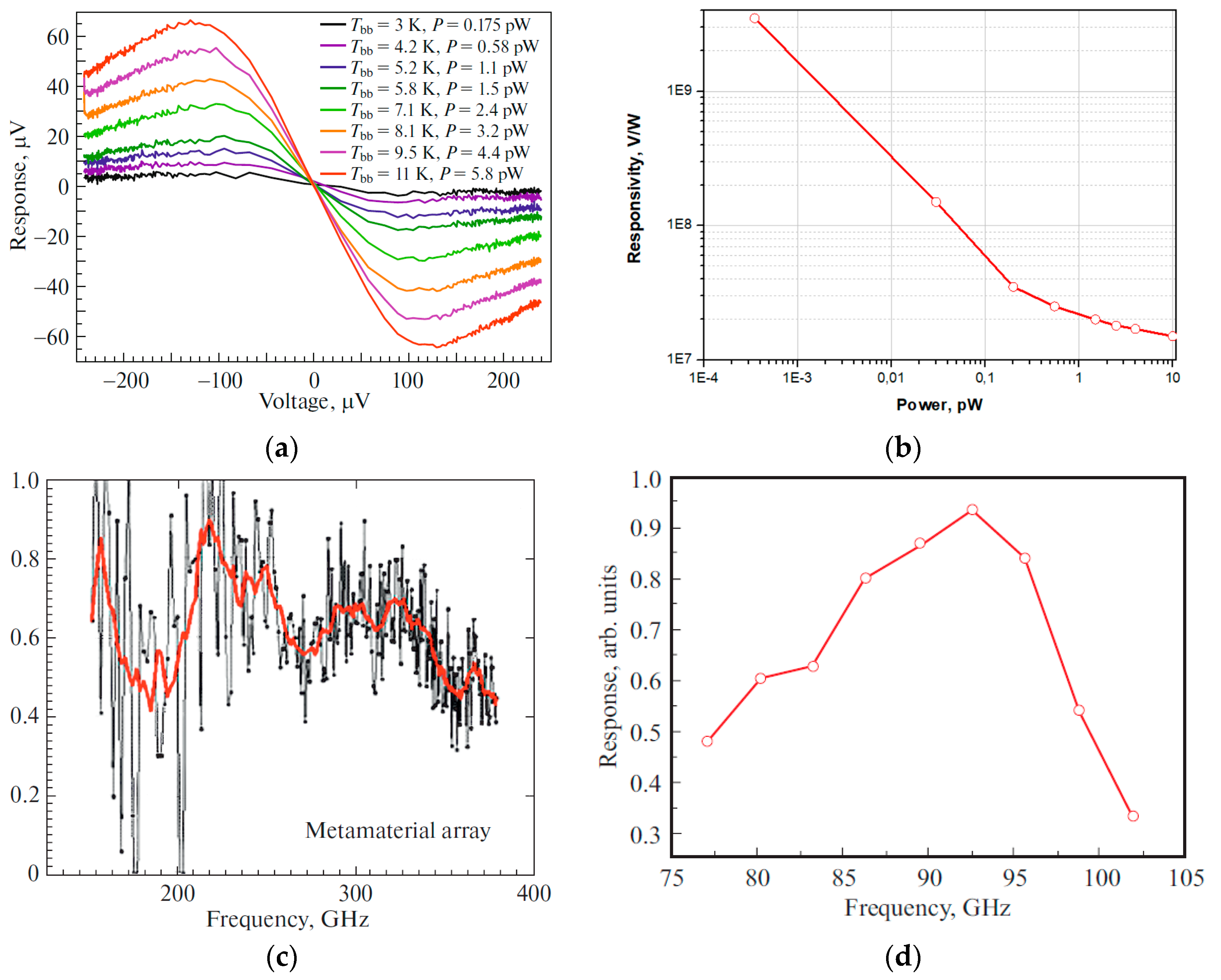
Figure 11). The sensitive element of such a structure is a submicron absorber made of normal metal (for example, depending on the available technology, aluminum with a sublayer of iron, copper, hafnium, palladium, etc. can be used), which is heated by incoming electromagnetic radiation. Two tunnel junctions of the normal metal-insulator-superconductor (NIS) structure act as thermometers. As it was theoretically shown in publication [24], SINIS detectors can operate in different modes (depending on the chosen topology) – from a photon counter to a bolometric mode with high quantum efficiency. For example, publications [25,26] present the implementation of a SINIS detector with a quantum efficiency of 15 electrons per quant of radiation with a frequency of 350 GHz. The saturation power of a single SINIS detector is of the order of 1 pW. By combining such structures into arrays, it is possible to significantly increase the saturation level of the detecting cell, which is fundamentally important for working in ground-based observatories in conditions of high background load (tens of picowatts). Typical characteristics of the arrays of such detectors are: volt-watt sensitivity up to 10
9 V/W, noise equivalent power is no worse than 10
-16 W/Hz
0,5 (and can be improved by replacing the warm readout electronics with frequency multiplexing with a cold HEMT amplifier). The frequency response of detecting devices based on SINIS structures is determined by the antenna/array of antennas into which detectors are integrated. In detail, the principle of operation of such detectors is given in publications [27,28]. Some typical measured characteristics of SINIS detectors are shown in
Figure 12.
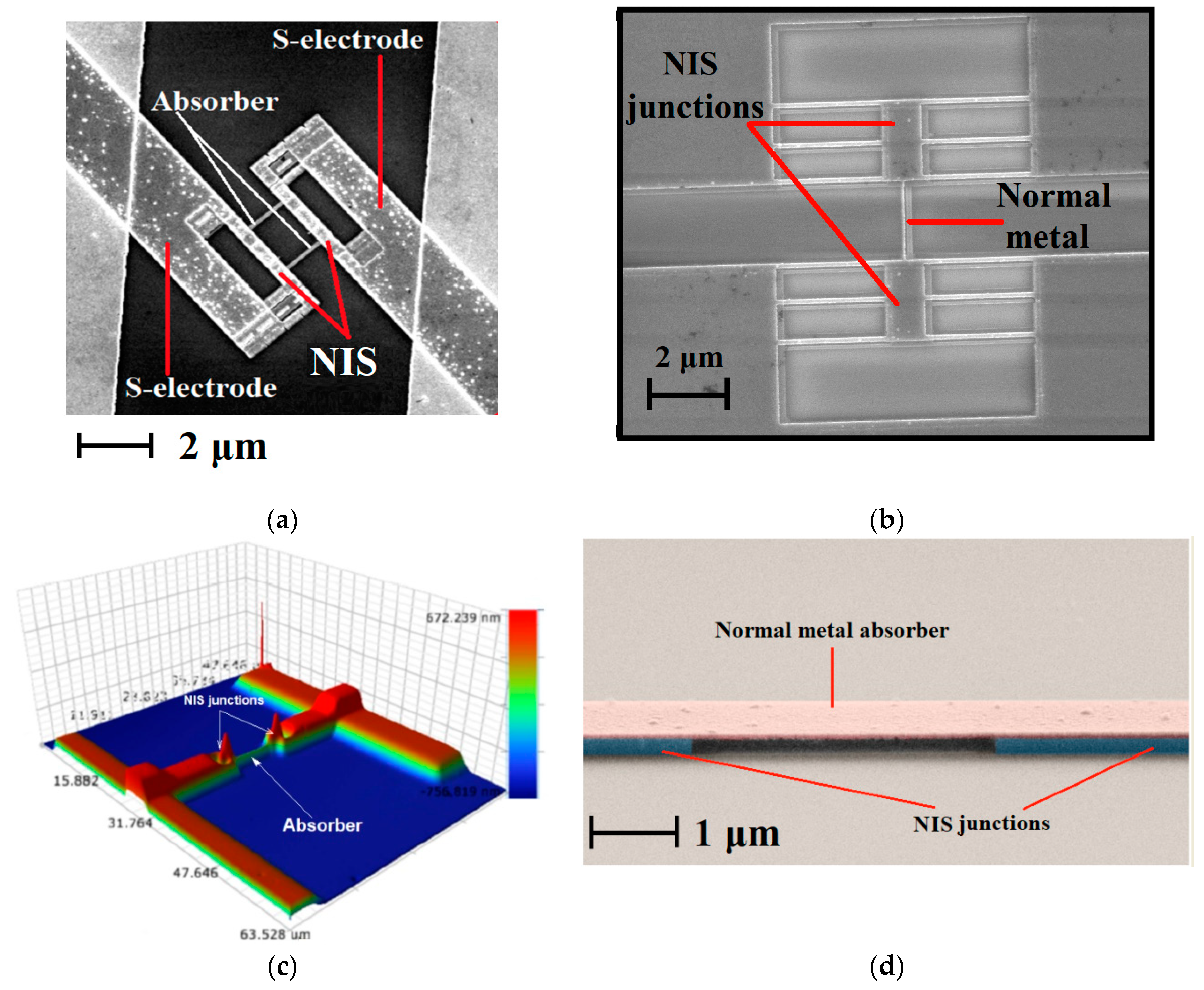
For the fabrication of such detection devices, various technologies can be used (depending on the topology and available technological equipment): shadow evaporation technique, bridge-free technology, technology with separate lithography and magnetron sputtering. In detail, different methods and approaches to the fabricate of such structures are given in the publication [29], photographs of SINIS bolometers fabricated using various technologies are shown in
Figure 13.
SINIS detectors themselves are non-selective structures – the frequency range and bandwidth are primarily determined by the planar antennas into which they are integrated, as well as by the nodes of the quasi-optical receiving path, various filtering elements, etc., installed on the source-detecting cell path. Due to the miniature size of the detectors, they can be easily integrated into various planar structures: single antennas, various frequency-selective surfaces, electrically small antennas, etc. Accordingly, there is no problem of switching to a higher frequency range: 1.3 and 0.8 mm (not only for the BTA, but also with the prospect of installation on instruments specifically designed for the subTHz range).
The assessment of the prospects and possibilities of working in these transparency windows will be carried out after the next cycle of atmospheric absorption research. But if we consider the prospects of using the BTA as part of the EHT, then it should be borne in mind that the SINIS structures are not suitable for an interferometer, the SIS receivers actively developed at the IRE RAS are suitable here. (for example, presented in [33,34]).
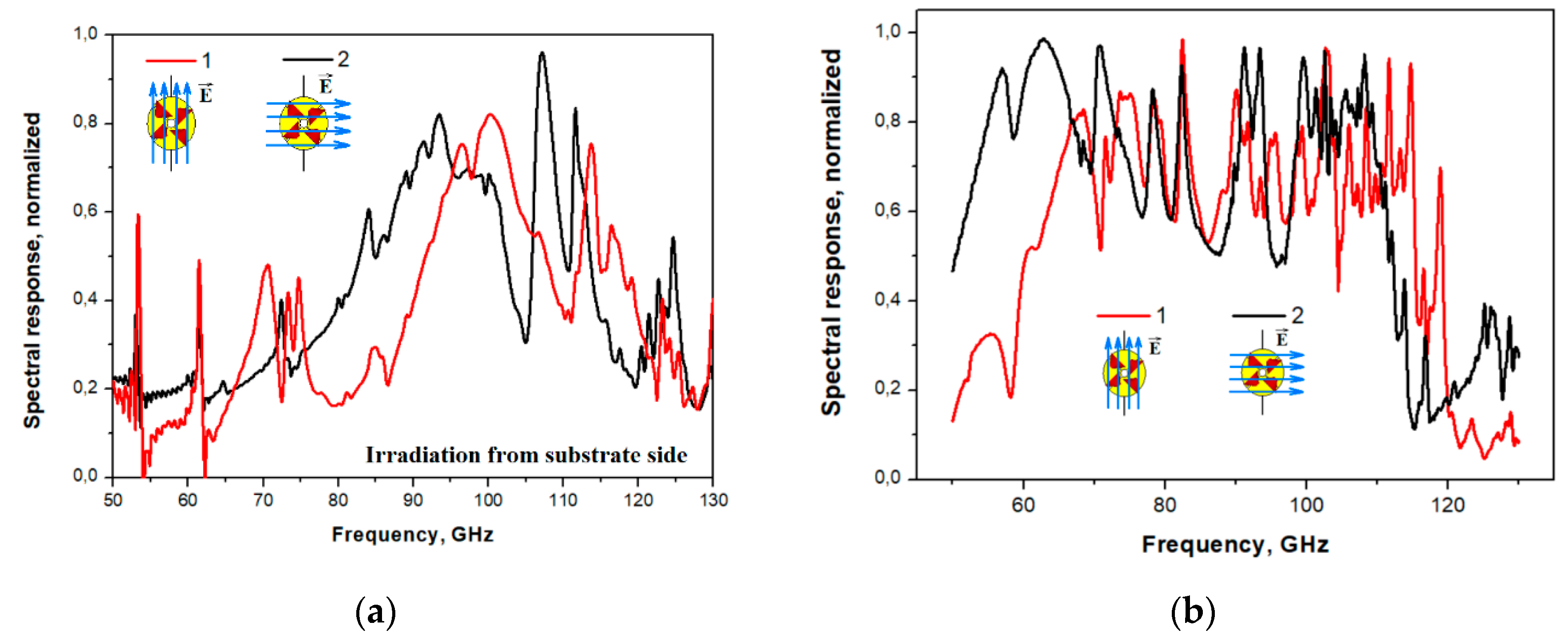
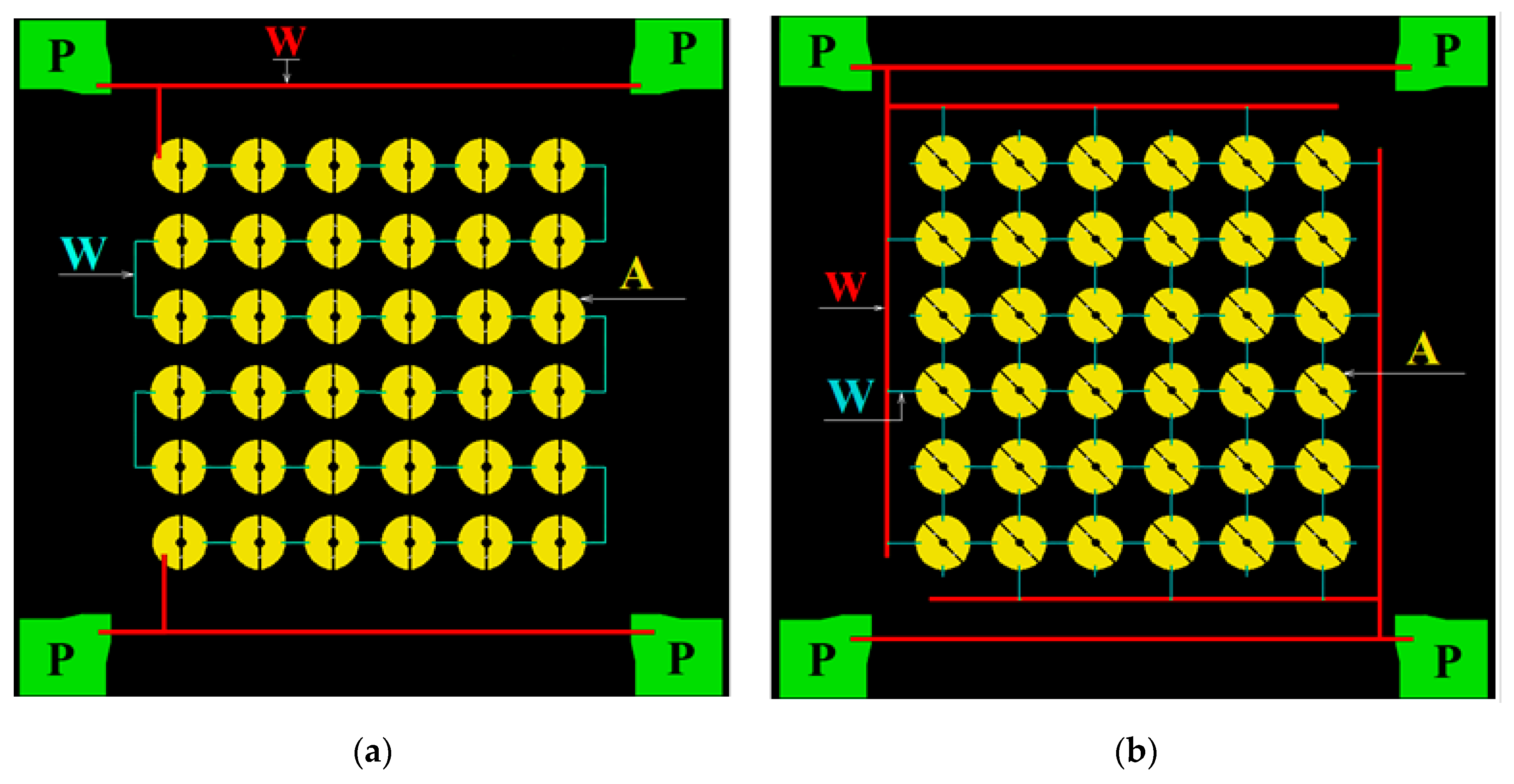
As noted above, for primary test studies, the 90 GHz range is assumed, which is the most convenient from the point of view of astroclimate conditions (observations can be carried out at any time of the year). Publication [28] presents the results of modeling arrays of receiving annular antennas in the 90 GHz range with irradiation from the substrate side and from the antenna side
Figure 14. The topology of such a structure was developed with two types of connection of array elements (serial and parallel),
Figure 15. Different types of connection of elements provide different resistance: about 36 kOhm and 15 Ohm, respectively. Different resistances of receiving matrices are considered for the possible use of different readout systems: high-resistance based on JFET transistors or low-resistance with SQUID amplifiers.
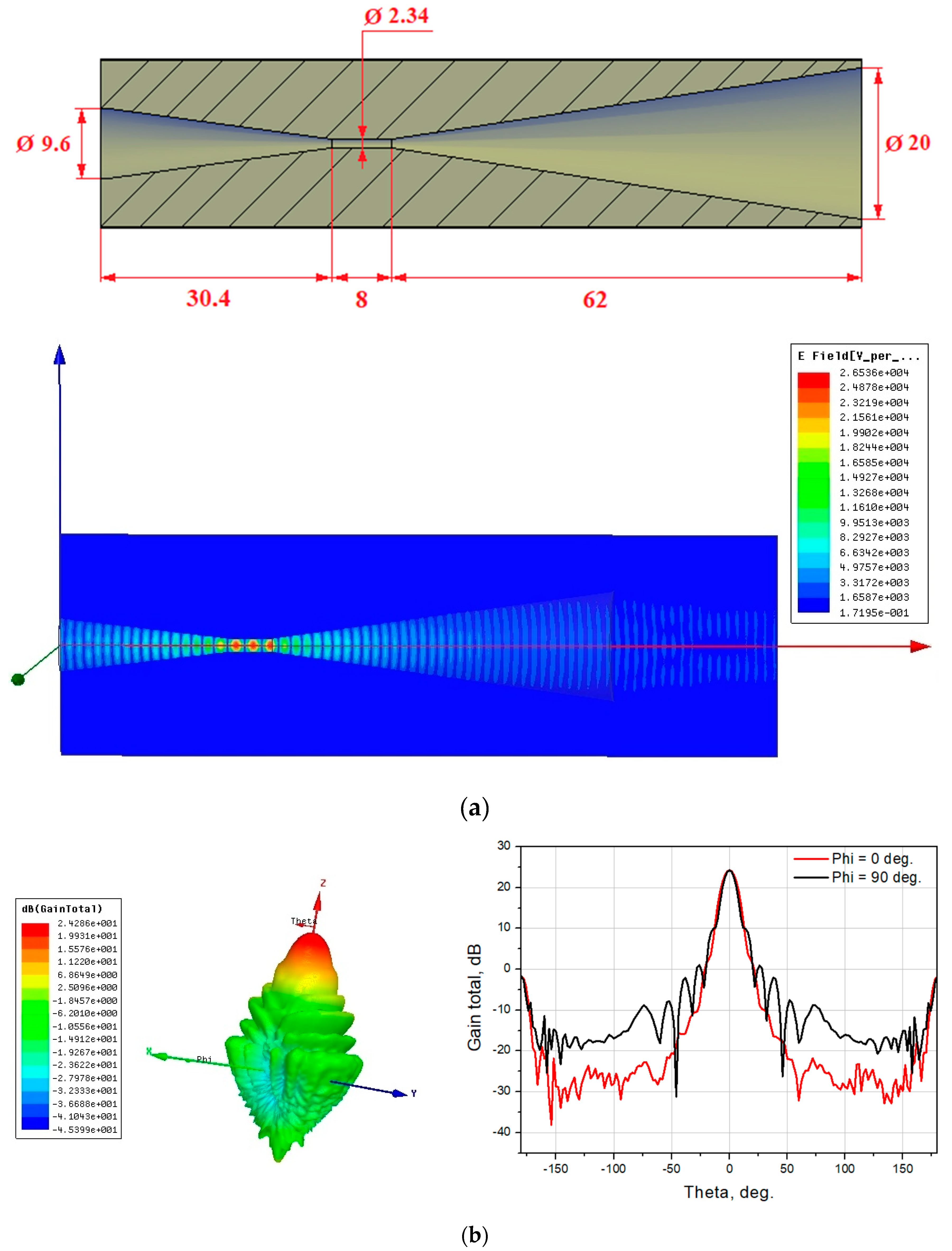
To match the incoming radiation with the receiving array, it is proposed to use the back-to-back horn. The choice of this design is due to the following: the best way to “cut” the frequency from below (in this case, 75 GHz) is to use a waveguide of a given diameter. The diameter of the waveguide with a critical frequency of 75 GHz is 2.34 mm. The developed receiving array fits into a circle with a diameter of 9.2 mm and it is impossible to place it directly in the waveguide. In this regard, an additional “transmitting” horn is used, located after the waveguide. A schematic representation of the back-to-back horn with dimensions and its radiation pattern is shown in
Figure 16.
3.4. Possible Relevant Astronomical Tasks in the subTHz Range for the BTA Telescope
Possible actual tasks at the BTA site:
The range is about 3 mm (convenient from the point of view of the astroclimate – studies can be carried out all year round), observations can be carried out for such tasks as:
Millimeter and submillimeter astronomy makes an invaluable contribution to the study of objects characterized by extremely high energy release – such as active galactic nuclei, which, apparently, are accreting supermassive black holes.
studies of lacertids (objects of the BL Lac type);
studies of distant quasars (for example, ULIRG QSO);
conducting observations of extragalactic objects and molecular clouds in our Galaxy in the CO J1-0 115.27 GHz line;
estimation of the fluxes of very distant galaxies recently discovered by the JWST Space Telescope (joint optical observation programs with BTA are possible).
4. Conclusions
The article proposes a project to use the capabilities of the BTA of the SAO RAS for radio astronomical observations in the MM and subMM range, which will potentially expand the capabilities of the BTA optical telescope. The results of preliminary assessments and studies presented in the article showed that the implementation of such a project is possible, and the team of co-authors of this work demonstrated here their readiness to solve rather unusual task of incorporation of a radio wave receiver as the sensor into the BTA optical telescope of the SAO RAS. This site can be used quite effectively both for testing receiving systems under the conditions of a real ground-based instrument, and for conducting radioastronomical researches on some current astrophysical problems of millimeter-wave astronomy, including to be an element of EHT.
In memory of the departed colleagues: the history of the project of mounting subTHz receivers on the site of the BTA optical telescope of the SAO RAS
In reality, the history of the project proposed for implementation in cooperation between SAO RAS, IAP RAS, IRE RAS and IPP RAS has a fairly long duration and has been extremely productive and fruitful. Initially, the idea was formulated and the first attempt was made to install an uncooled DBS receiver back in the late 80s - early 90s. With the help of a joint team, three of whom are the authors, a relatively successful experiment in installing a DBS receiver was carried out. But it was not possible to measure real astronomical objects; it was not clear whether the problem of quasi-optics was successfully solved, whether a glass optical mirror coated with a metal layer obviously thinner than the skin layer at mm waves reflects the mm signal well enough, etc. In the same years, the joint work of IRE and IAP was actively and successfully developed on the basis of the extensive competencies of IRE in superconducting receivers and IAP in cryogenic astronomical mm devices, on the creation of superconducting astronomical receivers. As a result, the first domestic receiver was launched on the RT-25*2 telescope in Zimenki near Nizhny Novgorod in 1991. But the dramatic turning point of 1991 prevented the continuation of these works. There was no money for them. However, the united team found new directions and means. The IAP team was invited by SAO specialists to work on cryogenic cooling of optical receivers for the BTA and other applications; as a result an extensive series (several dozen) of successfully operating cooled photodetectors was born, becoming a monopolist in this field for many years. Superconductor receivers created at IRE and IAP turned out to be in demand for foreign instruments RT-22 at KrAO, which became Ukrainian, and the Metsahovi Observatory (Finland). It is clear that over the years, no sub-THz antennas have appeared in Russia, and the RT25*2 radio telescope has ceased to exist. A new stage in the development of the topic was opened in the mid-2000s by A.N. Vystavkin, who proposed installing not a superheterodyne, but a bolometric subTHz receiver on the BTA. The topic of superconducting subTHz bolometers was actively advanced within the framework of this project, but alas, it was again not completed by installing the device at the focus of the telescope.
Finally, a new generation of researchers from the IAP and IRE have actively taken on this task. Prototype receivers have already been developed and tested in the laboratory. The problem of ultra-deep (up to 0.3 K) cooling of such a receiver at the telescope focus is being solved, which is also non-trivial. A Dewar with helium is not an easy thing, and the refrigerator has a compressor that generates vibrations at an unacceptable level for a telescope. However, both ideologies of subkelvin cooling presented above have been developed by a team of authors to a device that can be fully implemented on a telescope.
The authors are grateful to their colleagues and comrades who have invested their labor in this long-term work and believe that it will be successfully completed, dedicate it to our departed colleagues: D. Korolkov, G. Chuntonov, A.Berlin, A. Vystavkin, Yu. Lebsky, Yu.Dryagin, who were at the origins of the development of the idea of using a sub-THz radio receiver in an optical telescope.
Author Contributions
Conceptualization, Y.B.; methodology, V.D. and V.V.; software, G.B. and T.H; validation, P.Z.; formal analysis, A.R.; investigation, A.C., A.G, V.E., S.K, D.K, I.L., M.M., A.M, V.P., M.T.,G.Y. and R.Y.; resources, Y.B.; data curation, G.B., A.G and A.M.; writing—original draft preparation, A.G and V.V.; writing—review and editing, A.G, V.V, P.Z and I.Z..; project administration, V.V . All authors have read and agreed to the published version of the manuscript.
Funding
The development of cryogenic systems for cooling of the subTHz receiving device on the BTA telescope of SAO RAS is supported by the grant of the Russian Science Foundation # 23-62-10013“" Development of Russian subterahertz observatory prototype as part of an optical telescop”". The equipment of USU “Cryointegral” was used for fabrication of receiving structures; USU is supported by a grant from the Ministry of Science and Higher Education of the Russian Federation, agreement No. 075-15-2021-667. The study of reflection losses of the “witness”, the development and manufacture of various electrical and mechanical interfaces for the studying of receiving structures, as well as the development of cryogenic systems were carried out on the basis of Large-scale research facilities “Center of Microwave Research of Materials and Substances” (CKP-7, USU # 3589084)..
Conflicts of Interest
The authors declare no conflict of interest”.
References
- Kislyakov, A.G. Radioastronomical investigations in the millimeter and submillimeter bands. Sov. Phys. Usp 1971, 13, 495–521. [CrossRef]
- Day, P.; Leduc , H.G.; Dowell, C.D.; Lee, R.A.; Turner, A.; Zmuidzinas, J. Distributed Antenna-Coupled TES for FIR Detector Arrays. Journal of Low Temperature Physics 2008, 151, 477-482. [CrossRef]
- Westbrook, B.; Cukierman, A.; Lee, A.; Suzuki, A.; Raum, C.; Holzapfel, W. Development of the Next Generation of Multi-chroic Antenna-Coupled Transition Edge Sensor Detectors for CMB Polarimetry. Journal of Low Temperature Physics 2016, 184, 74-81. [CrossRef]
- Day, P.K.; LeDuk, H.G.; Mazin, B.A.; Vayonakis, A.; Zmuidzinas, J. A broadband superconducting detector suitable for use in large arrays. Nature 2003, 425, 817-821. [CrossRef]
- Paiella, A.; Ade, P.A.R.; Battistelli, E.S.; et.al. In Flight Performance of the LEKIDs of the OLIMPO Experiment. Journal of Low Temperature Physics 2020, 199, 491-501. [CrossRef]
- Zinchenko, I.I. Contemporary millimeter and submillimeter-wave astronomy. Radiophysics and Quantum Electronics 2003, 46, 577-593.
- Kardashev, N. S.; Novikov, I.D.; Lukash, V.N.; et.al. Review of scientific topics for Millimetron space observatory. Phys. Usp. 2014, 57, 1199-1228. [CrossRef]
- Novikov, I.D.; Likhachev, S.F.; Shchekinov, Yu.A.; et.al. Objectives of the Millimetron Space Observatory science program and technical capabilities of its realization. Phys. Usp. 2021, 64, 386-419. [CrossRef]
- 9. Institute of Applied Astronomy Russian Academy of Science. Available online: https://iaaras.ru/en/quasar/ (accessed on 30 October 2023).
- 10. Dmitrov Branch of the Bauman Moscow State Technical University. Available online: https://df.bmstu.ru/?p=rt7.5 [in Russian] (accessed on 30 October 2023).
- Vdovin, V.F.; Artemenko. Y.N.; Balega, Y.Y.; et.al. New stage of the Suffa Submm Observatory in Uzbekistan Project. In Proceedings of the 30th International Symposium on Space THz Technology (ISSTT2019), Gothenburg, Sweden, April 15-17, 2019.
- 12. Special Astrophysical Observatory of Russian Academy of Science. Available online: https://www.sao.ru/Doc-en/Telescopes/bta/descrip.html (accessed on 30 October 2023).
- Bubnov, G.M..; Grigorev, V.F.; Vdovin, V.F.; Zemlyanukha, P.M.; Zinchenko, I.I. Zinchenko. 30th International Symposium on Space THz Technology (ISSTT2019), Gothenburg, Sweden, April 15-17, 2019.
- Nosov, V.I.; Bolshakov, O.S.; Bubnov, G.M.; Vdovin, V.F.; Zinchenko, I.I.; Nikiforov, P.L.; Fedoseev, L.I.; Shvetsov, A.A.; Marukhno, A.S. A Dual-Wave Atmosphere Transparency Radiometer of the Millimeter Wave Range. Instruments and Experimental Techniques 2016, 59, 374-380. [CrossRef]
- Bubnov, G.M.; Grigor'ev, V.F.; Zinchenko, I.I.; Zemlyanukha, P.M.; Il'in, G.N.; Kabanov, D.M.; Nosov, V.I.; Vdovin, V.F.; Consistent determination of the integral humidity and effective optical depth of the atmosphere in the millimeter wavelength range using wideband radiometers. Consistent determination of the integral humidity and effective optical depth of the atmosphere in the millimeter wavelength range using wideband radiometers 2020, 62, 820-829. DOI: 10.1007/s11141-020-10027-x.
- Bubnov, G.M.; Abashin, E.B.; Balega, Yu.Yu.; Bolshakov, O.S..; Dryagin, S. Yu; Dubrovich, V.K.; Marukhno, A.S.; Nocov, V.I.; Vdovin, V.F.; Zinchenko, I.I.; Searching for New Sites for THz Observations in Eurasia. IEEE Transactions on Terahertz Science and Technology 2015, 5, 54-72. [CrossRef]
- 17. Special Astrophysical Observatory of Russian Academy of Science/ MirrorChronicle. Available online: https://www.sao.ru/Doc-en/Events/2018/MirrorChronicle/index.html (accessed on 30 October 2023).
- Parshin, V.V; Serov, E.A.; Bubnov, G.M.; Vdovin, V.F.; Koshelev, M.A.; Tretyakov, M.Yu. C.D. Cryogenic Resonator Complex. Radiophysics and Quantum Electronics 2014, 56, 554-560. [CrossRef]
- Goldsmith, P.F. Quasi-Optical Techniques. PROCEEDINGS OF THE IEEE 1992, 80, 1729-1747. [CrossRef]
- Brückner, C.; Pradarutti, B.; Müller, R.; Riehemann, S.; Notni, G.; Tünnermann, A. Design and evaluation of a THz time domain imaging system using standard optical design software. Appl. Opt. 2008, 47, 4994-5006. [CrossRef]
- Jördens, C.; Thorwirth, G.; Koch, M. An optical design for real-time terahertz imaging. In Proceedings of the German Microwave Conference 2006, Karlsruhe, Germany, 2006.
- Edelman, V.S. A DILUTION MICROCRYOSTAT-INSERT. Instruments and Experimental Techniques 2009, 52, 301-307. [CrossRef]
- Balega, Yu.Yu.; Bolshakov, O.S.; Chernikov, A. Cryogenic systems for astronomical research in SAO RAS. To be publish in MDPI Photonics in Special Issue “Optical Systems for Astronomy” 2023. [CrossRef]
- Devyatov, I.A.; Krutitskiĭ, P.A.; Kupriyanov M.Yu. Investigation of various operation modes of a miniature superconducting detector of microwave radiation. JETP Letters 2006, 84, 57-61. [CrossRef]
- Tarasov, M.; Edelman, V.; Mahashabde, S.; Fominsky, M.; Lemzyakov, S.; Chekushkin, A; Yusupov, R.; Winkler, D.; Yurgens, A; Electrical and optical properties of a bolometer with a suspended absorber and tunneling-current thermometers. APPLIED PHYSICS LETTERS 2017, 110, article number: 242601. [CrossRef]
- Yusupov, R.A.; Gunbina, A.A; Chekushkin, A.M.; Naginaya, D.V; Lemzyakov, S.A.; Edelman, V.S.; Tarasov, M.A. Quantum Response of a Bolometer Based on the SINIS Structure with a Suspended Absorber. Physics of the Solid State 2020, 62. [CrossRef]
- Tarasov, M.; Gunbina, A.; Chekushkin, A.; Ysupov, R.; Edelman, V.; Koshelets, V. Microwave SINIS Detector. Applied Science 2022, 12, article number: 10525. [CrossRef]
- Tarasov, M.; Gunbina, A.; Chekushkin, A.; Ysupov, R.; Edelman, V.; Vdovin, V. SINIS detectors: 30 years of achievements and delusions. IEEE 8th All-Russian Microwave Conference 2023, RMC.
- Gunbina, A.; Tarasov, M.; Fominsky, M.; Chekushkin, A.; Yusupov, R.; Nagirnaya, D. Fabrication of Aluminium Nanostructures for Microwave Detectors Based on Tunnel Junctions. In Book In Advances in Microelectronics Reviews, Yurish, S.Y. Eds.; IFSA Publishing, S.L.: Barcelona, Spain. 2021; Volume 3, pp. 183–212.
- Tarasov, M.; Gunbina, A.; Mahashabde, S.; Ysupov, R.; Chekushkin, A.; Nagirnaya, D.; Edelman, V.; Yakopov, G.; Vdovin, V. Arrays of Annular Antennas With SINIS Bolometers. Abbreviated Journal Name Year, Volume, page range. [CrossRef]
- Gunbina, A.A; Tarasov, M.A.; Lemzyakov, S.A.; Chekushkin, A.M.; Ysupov, R.A.; Nagirnaya, D.V.; Mansfeld, M.A.; Vdovin, V.F; Winkler, D.; Kalaboukhov, A.S.; Edelman, V.S. Spectral Response of Arrays of Half-wave and Electrically Small Antennas with SINIS Bolometers. Physics of the Solid Stat 2020, 62, 1604-1611. [CrossRef]
- Gunbina, A.; Mahashabde, S.; Tarasov, M.; Yakopov, G.; Ysupov, R.; Chekushkin, A.; Nagirnaya, D.; Lemzyakov, S.; Vdovin, V.; Kalaboukhov, A.; Winkler, D. A 90 GHz SINIS Detector With 2 GHz Readout. IEEE TRANSACTIONS ON APPLIED SUPERCONDUCTIVITY 2021, 31 article number: 1500805. [CrossRef]
- Dmitriev, P. N.; Filippenko, L.V.; Koshelets, V.P. Josephson Junctions. History, Devices, and Applications. In Book Title, New York : Jenny Stanford Publishing; 2007, pp. 185-244. [CrossRef]
- Rudakov, K.I.; Khudchenko, A.V.; Filippenko, L.V.; et al. THz Range Low-Noise SIS Receivers for Space and Ground-Based Radio Astronomy. Appl. Sci. 2021, 11, Art.#10087. [CrossRef]
Figure 1.
BTA: (a) – The photo of telescope; (b) – Design scheme: 1 – platform, 2 – spherical ring, 3 – axis, 4 – radial bearing, 5 – liquid friction support, 6 – wheel block, 7 – rack, 8 – working balconies, 9 – balcony bracket, 10 – elevator, 11 – lower ring, 12 – “mullion”, 13 – upper ring, 14 – lower rod, 15 – upper rod, 16 – main mirror frame with unloading device, 17 – cantilever beams, 18 – hydrostatic cushions, 19 – worm gear, 20 – cable drum, 21 – primary focus cup, 22 – observer’s cabin, 23 – fixed mirror focus, 24 – main stellar spectrograph.
Figure 2.
Radiometer MIAP-2: (a) Functional scheme of the receiver unit and (b) a photo of the device.
Figure 2.
Radiometer MIAP-2: (a) Functional scheme of the receiver unit and (b) a photo of the device.
Figure 3.
Cumulative distributions of brightness temperature (for 1.3 and 0.8 mm, the data were recalculated through water) in various atmospheric transparency windows: (a) 3 mm, (b) 2 mm, (c) – 1.3 mm and (d) 0.8 mm.
Figure 3.
Cumulative distributions of brightness temperature (for 1.3 and 0.8 mm, the data were recalculated through water) in various atmospheric transparency windows: (a) 3 mm, (b) 2 mm, (c) – 1.3 mm and (d) 0.8 mm.
Figure 4.
Histograms of the distribution of observation time at the BTA site by monthes (a) and seasons (b).
Figure 4.
Histograms of the distribution of observation time at the BTA site by monthes (a) and seasons (b).
Figure 5.
Photos from the expedition to the SAO RAS: (a) Photo of the observatory, (b) Photo of the six–meter mirror of the BTA telescope, (c) Photo of the primary focus of the BTA, (d) Measurement of landing sites in the second Nasmith focus of the BTA telescope.
Figure 5.
Photos from the expedition to the SAO RAS: (a) Photo of the observatory, (b) Photo of the six–meter mirror of the BTA telescope, (c) Photo of the primary focus of the BTA, (d) Measurement of landing sites in the second Nasmith focus of the BTA telescope.
Figure 6.
The “witness” sample: A photo of the samples (a) and measured reflection losses (b): the red graph shows measurements, the black line is extrapolation.
Figure 6.
The “witness” sample: A photo of the samples (a) and measured reflection losses (b): the red graph shows measurements, the black line is extrapolation.
Figure 7.
Schematic representation of the Nasmith I scheme of the BTA telescope of SAO RAS.
Figure 7.
Schematic representation of the Nasmith I scheme of the BTA telescope of SAO RAS.
Figure 8.
The radius of a Gaussian beam propagating in the Nasmith I scheme of the BTA telescope of the SAO RAS.
Figure 8.
The radius of a Gaussian beam propagating in the Nasmith I scheme of the BTA telescope of the SAO RAS.
Figure 9.
Huygens PSF cross section X for λ=1303 μm (230 GHz) and λ=2998 μm (100 GHz).
Figure 9.
Huygens PSF cross section X for λ=1303 μm (230 GHz) and λ=2998 μm (100 GHz).
Figure 10.
Various cryostat systems in which studies of the developed detection devices were carried out: (a) a cryostat with 3He vapor pumping Heliox AC-V manufactured by Oxford Instruments; (b) a filler cryostat-insert developed at the P.L. Kapitsa Institute of Physical Problems of the Russian Academy of Sciences.
Figure 11.
Schematic image of the SINIS structure: top view and side view of different designs of the SINIS detector– with an absorber on a substrate (left) and with a suspended absorber (right).
Figure 11.
Schematic image of the SINIS structure: top view and side view of different designs of the SINIS detector– with an absorber on a substrate (left) and with a suspended absorber (right).
Figure 12.
Typical measured characteristics of SINIS detectors: (a) voltage responses of a single SINIS detector with a suspended absorber at a temperature of 120 mK to black body radiation of different power [26]. (b) Responsivity dependence on power for single bolometer in the series array measured at 100mK with cryogenic blackbody source (graph from the publication [30]); (c) Spectral response of an array of electrically small antennas with integrated SINIS detectors of the 350 GHz range [31]; (d) Spectral response of a single double-slot antenna of the 90 GHz band with an integrated SINIS detector [32].
Figure 13.
Photos of fabricated SINIS detectors: (a) a photograph from a scanning electron microscope of a SINIS structure made by shadow evaporation; (b) SINIS detector made by a bridge–free technology; (c) SINIS detector made by separate lithography with magnetron sputtering; (d) a SINIS detector with a suspended absorber. Photos a,b, and d are taken from the publication [29].
Figure 14.
Simulation results of the spectral response of an array of annular antennas with integrated 90 GHz SINIS detectors: irradiation from the substrate (a) and irradiation from the antennas (b). Figure from the publication [28].
Figure 14.
Simulation results of the spectral response of an array of annular antennas with integrated 90 GHz SINIS detectors: irradiation from the substrate (a) and irradiation from the antennas (b). Figure from the publication [28].
Figure 15.
Topology of arrays with integrated SINIS detectors of the 90 GHz range: series connection of elements (a) and parallel connection (b). P – contact pads for picking up and sending a signal from/to the array; W – connecting wires (red – wide (50 µm) wires from the array, connecting to the contact pads; blue – narrow (2 µm) for connecting elements to each other); A – antennas, each of which has two SINIS detectors integrated.
Figure 16.
Calculated back-to-back horn for matching the receiving array with the incoming signal, dimensions are given in millimeters: (a) Schematic representation of the horn with dimensions and (b) Directional pattern of the horn.
Figure 16.
Calculated back-to-back horn for matching the receiving array with the incoming signal, dimensions are given in millimeters: (a) Schematic representation of the horn with dimensions and (b) Directional pattern of the horn.
Table 1.
The radius of the Gaussian beam before and after the Nasmith tube and the fraction of the passing power.
Table 1.
The radius of the Gaussian beam before and after the Nasmith tube and the fraction of the passing power.
| |
100 GHz |
230 GHz |
| Before tube (18039 mm) |
79,036 mm |
63,08 mm |
| After tube (20784 mm) |
63,638 mm |
32,148 mm |
| At Nasmyth focus according to Zemax OpticStudio |
80,29 mm |
56,04 mm |
| Percentage of transmitted power |
97,9 % |
99,8% |
|
Disclaimer/Publisher’s Note: The statements, opinions and data contained in all publications are solely those of the individual author(s) and contributor(s) and not of MDPI and/or the editor(s). MDPI and/or the editor(s) disclaim responsibility for any injury to people or property resulting from any ideas, methods, instructions or products referred to in the content. |
© 2023 by the authors. Licensee MDPI, Basel, Switzerland. This article is an open access article distributed under the terms and conditions of the Creative Commons Attribution (CC BY) license (http://creativecommons.org/licenses/by/4.0/).
