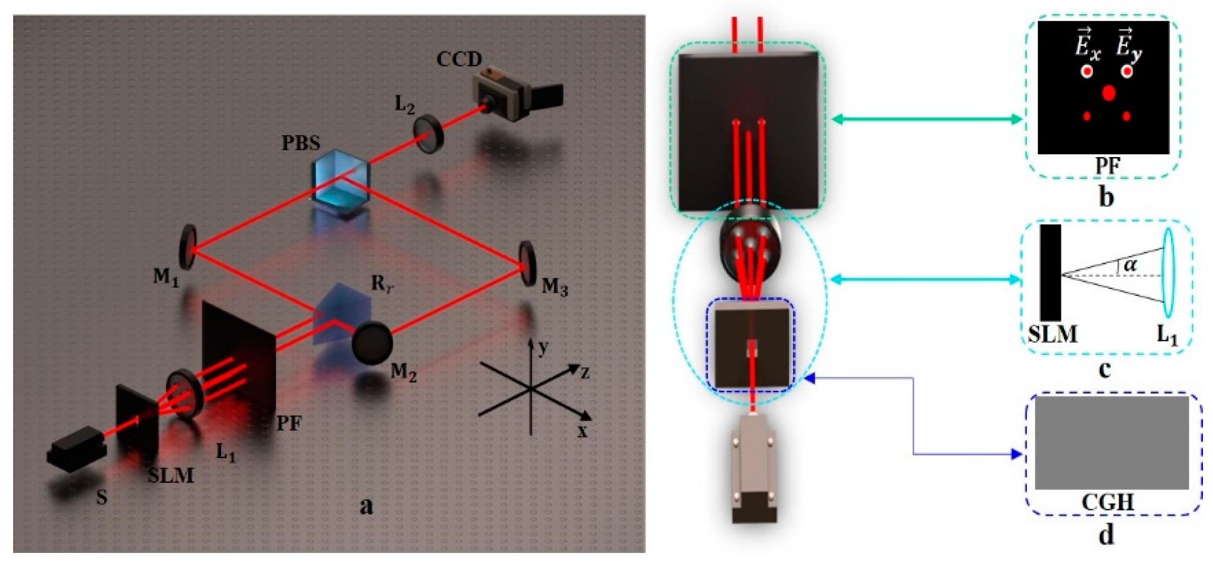
1. Introduction
Presently, nearly all applications involving light rely on the dimensional resources of photons. It is common knowledge that electrons possess extremely restricted dimensions, such as electron spin. Photons, on the other hand, are distinguished by their multiple dimensions. Photons' fundamental dimensions consist of wavelength/frequency, time, complex amplitude, polarization, and spatial domain. By modifying the photons' spatial domain, one can generate a vector light field. The polarization characteristics of the vector field make it have broad application prospects in the fields of transverse or longitudinal super-resolution [
1,
2], optical needle [
3,
4], optical information transmission [
5], optical chain [
6], optical channel [
7], particle capture, and manipulation [
8,
9].
Obviously, the generation of a vector light field is the premise of studying its novel characteristics and developing its new applications. In previous reports, the known generation techniques were mainly divided into the intracavity method and the extra-cavity method. The intracavity method not only requires a specific design of the resonant cavity but also only generates a vector light field with a specific polarization distribution. In contrast, the extra-cavity method is very flexible. Different vector light fields can be obtained by adjusting the optical path or element, which makes the generation of vector light fields diverse. The main devices involved are the optical metasurface [
10,
11,
12], q plate [
13], cylindrical lens [
14,
15], bifurcated grating [
16], spiral phase plate [
17,
18] and SLM [
19]. Among them, the polarization state and complex amplitude distribution of the vector light field can be adjusted in real time by means of SLM, which highlights the flexibility of the extra-cavity method. Therefore, the vector light field generation method based on SLM is widely used. For example, Ding 's research group [
20] divided the incident beam into two beams from the computer-generated hologram (CGH) written to the SLM. Each beam is encoded using the specified complex field, and then effectively combined into a single vector beam through the Wollaston prism. In the triangular co-pass interferometer system proposed by Zhao Jianlin 's research group [
21], a beam of light passes through the beam splitting system first, and then two orthogonal polarization components are reflected by a right-angle prism to the left and right regions on the screen of the SLM, respectively. And then coupled through the combined beam system to form a single vector beam. Carmelo et al. [
22] can simultaneously generate multiple vector beams with different spatial shapes and polarization distributions by using the interference method and the optical superposition principle. Compared with the former two, this greatly improves the generation efficiency of vector beams and increases the types of generation. However, it is limited to the generation of vector beams with cylindrical symmetry. In the path, it is necessary to use wave plates to adjust, and the requirements for optical path construction are strict, which will increase the difficulty of actual operation.
In this paper, a modulation method based on liquid crystal SLM is proposed. By using the coding method based on the modified off-axis interference hologram, combined with the transmission liquid crystal SLM and a shunt coupling system, the multimode vector light field with an arbitrary complex amplitude distribution is finally generated. Complex optical components are not involved in the whole experiment. The optical system is small in size, which reduces the complexity of the experimental optical path, and the vector beam quality is high. As a proof of principle, the experimental results show that this method can not only generate multiple types of vector beams at the same time, but also that the beam waist radius, topological charge number, polarization order, and additional phase of each beam are independently controllable. In addition, although we only show 12 cylindrically symmetric vector beams, the actual number is much larger than this, which is mainly limited by the resolution of SLM. If the resolution region of SLM is idealized, infinite vector beams can be generated.
Section 2 introduces the experimental methods and theoretical analysis of this work.
Section 3 shows the experimental results and discussion.
3. Results and discussion
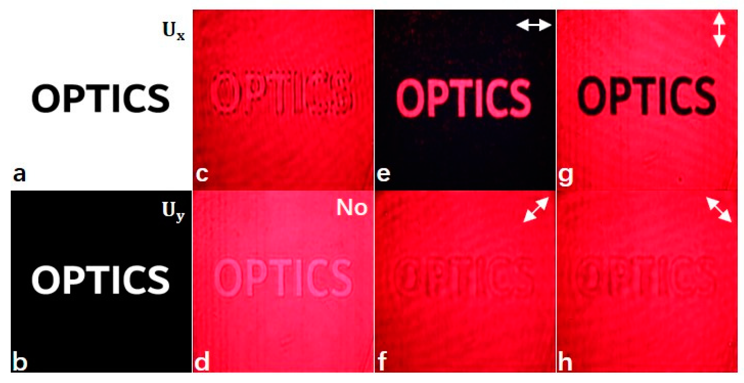
In order to ensure that the two orthogonal polarization components have independent imaging capabilities and determine the system parameters, two binary grayscale images with black and white in
Figures 2a,b are substituted into Equation (2) as the
component and the
component, respectively, to control the additional phase of the vector light field. The period and distribution of the moiré fringes (as shown in
Figure 2c) generated during the control process can explain the periodic difference between the two orthogonal polarization components and the direction of relative tilt. The system parameters can be defined by eliminating the moiré fringes (as shown in
Figure 2d), which is known by the formula (1) that controlling a vector beam requires the modulation of its four degrees of freedom, respectively; that is, the two vertical partitions of a vector beam will have their respective spatial frequency parameters
in the x and y directions, and by modulating the four spatially-frequency partition parameters separately, the
component and
component are finally common and coplanar. The background gray values in
Figure 2a,b are 1 and 0, respectively, and the gray values of ' O ', ' P ', ' T ', ' I ', ' C ' and ' S ' are 0 and 1, respectively. The additional phases corresponding to the image gray values of 0 and 1 are 0 and
, respectively.
Figure 2d shows that the intensity of the light field is evenly distributed without the polarizer, because the amplitude of the light field is not additionally regulated. When the polarization direction of the polarizer is horizontal, the light intensity of the background light is the smallest, and the light intensity of the four characters of ' O ', ' P ', ' T ', ' I ', ' C ' and ' S ' of horizontal linear polarization is the largest. The experimental results are shown in
Figure 2e. When the polarization direction of the polarizer is 45°, the light intensity of characters' O ', ' P ', ' T ', ' I ', ' C ' and ' S ' is the same as that of the background light. The experimental results are shown in
Figure 2f. When the polarization direction of the polarizer is vertical, the light intensity of the background light is the largest, and the light intensity of the four characters of ' O ', ' P ', ' T ', ' I ', ' C ' and ' S ' is the smallest. The experimental results are shown in
Figure 2g. When the polarization direction of the polarizer is 135°, the intensity of the four characters of ' O ', ' P ', ' T ', ' I ', ' C ' and ' S ' is the same as that of the background light. The experimental results are shown in
Figure 2h. Through the above experimental results, it can be seen that in the case of a polarizer, due to the background and the different polarization directions of different words, different light intensity distribution effects will be presented. It is verified that the two orthogonal polarization components of the vector beam in this method have good imaging ability, and the additional phase is controllable.
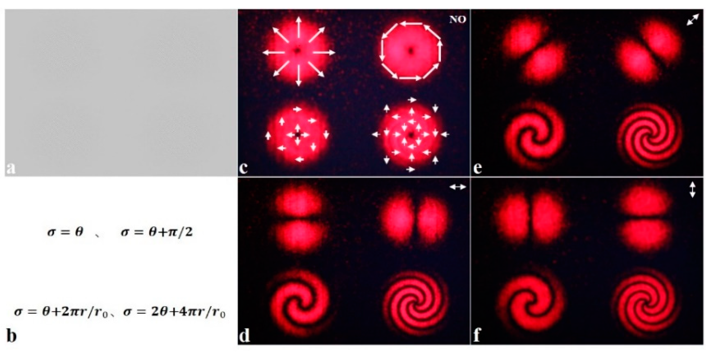
In order to verify that this method can produce multiple vector light fields simultaneously, a special calculated holography is produced. The first row of the figure, from left to right, is the diameter of the vector beam, the rotating vectorial beam of light, and the second row is the vibrant beam, as shown in
Figure 3a.
The additional phase of the column-symmetric vector light field can be synthesized with the rotating variable and the diameter variable in both cases, so that its additional phase can be expressed as:
Among them, (,) is the polar coordinate of the input plane, satisfying: , , is the radius on the cross section of the light wave, is the spot radius of the Hermitian Gaussian beam, is the initial phase, integer is the topological charge of the required vector beam, and is the radial index of the required vector beam.
Figure 3c is the light field intensity distribution map without the polarizer, and the polarization direction of each point is marked in the map.
Figure 3d-f shows the intensity distribution of the light field when the polarizer is at 0°, 45° and 90° respectively. It can be seen from these three figures that when the angle of the polarizer changes, the radial vector beam and the azimuth vector beam will change accordingly. In this process, the extinction direction of the radial vector beam is always perpendicular to the polarizer, while the azimuth vector beam rotates counterclockwise at the same angle. In summary, this method can produce multiple vector light fields at the same time and improve image quality.
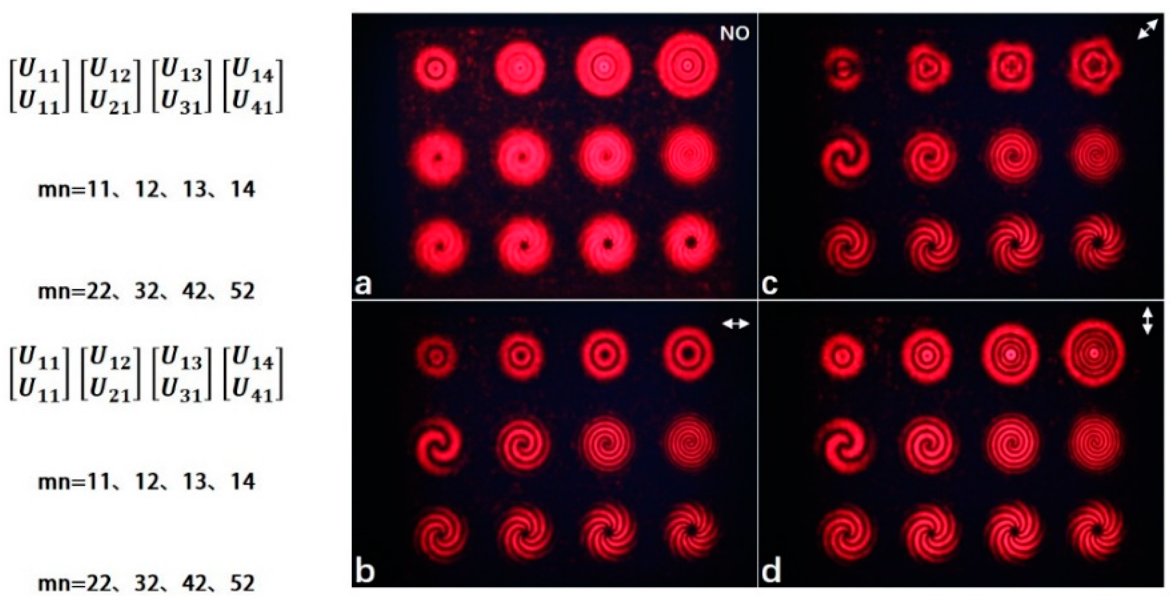
In order to ultimately determine that this method can produce several different types of vector beams simultaneously and that each beam can be independently controlled by its waist radius, topological charge number, polarization order, and additional phase, a special design of a multi-vector light field holography shows a total of 12 different patterns (take
=3,
=4): the first row is four kinds of Laguerre-Gaussian vector light beams, and vector beams with different radial exponents and topological charges in the second and third rows, as shown in
Figure 4a.
Among them, the Laguerre-Gaussian beam, a typical spiral phase distribution of uneven turbulent vector beams, can be rewritten (1) as:
Where is the normalized constant, is the beam width, and is the Laguerre polynomial. A scalar Laguerre-Gaussian beam is a typical optical vortex whose topological charge is equal to an integer . For Laguerre-Gaussian vector beams, due to the existence of the orthogonal polarization state, the topological charge has different vectors.
The results shown in
Figure 4a–d are the experimental results of a multimode vector light field without polarizer, 0°, 45° and 90° respectively.
Figure 4a shows the sampling of the total intensity distribution of the output multi-mode vector beam by CCD when the polarizer is not placed. Due to the lack of additional regulation of the complex amplitude of the light field, the light intensity of each spot is evenly distributed in this state. There are central dark spots in the 12 patterns in the figure. The central dark spot in the first row is caused by the fact that the center of the Laguerre-Gaussian beam is a dark core, that is, the central light intensity here is zero. In the second row, when the topological charge
is constant, the area of the central dark spot will decrease with the increase of the radial index
. In the third row, when the radial index
is constant, the area of the central dark point will increase with the increase in the topological load
. The central dark point in the second row and the third row is collectively referred to as the phase singularity. The reason for the phase singularity is that the phase of the light wave field becomes uncertain and the amplitude of the field is zero. Another reason is that the polarization distribution of the polarized light at the center point is the same, but the phase is opposite, so the interference condition is satisfied and the destructive interference dark spot is formed.
Figure 4b shows the intensity distribution of the multimode vector beam when the polarizer is 0°. It can be seen from the diagram that when the first row,
is constant, the radius of the extinction ring increases gradually with the increase of the topological charge
. The second row, with the increase of the radial index
, the radius of the spiral extinction gradually decreases; The third row says, “with the increase of topological charge
, the spiral extinction of the vector beam increases gradually, and the number is 2|
|. The intensity distribution rotates counterclockwise with the polarizer, and the extinction is a left-handed spiral.”
Figure 4c is the intensity distribution of a multimode vector beam when the polarizer is 45°. By observing the first row of the diagram, it can be seen that the shape of the Laguerre-Gaussian spot is changed into linear, triangular, quadrilateral and pentagon, respectively.
Figure 4d shows the intensity distribution of the multimode vector beam when the polarizer is 90°. It can be seen from the first row of the figure that when the topological charge
is constant, the number of extinction rings increases with the increase of
and the number is |
|. In the second and third rows in
Figure 4c, and 4d, the same phenomenon occurs as in the second and third rows in
Figure 4b, the only difference is that they are equivalent to rotating 45° and 90°, respectively, on the basis of
Figure 4b. Based on the above experimental results, it can be seen that the beam waist radius, topological charge number, polarization order, and additional phase of each beam can be independently controlled using this method. The first and second columns of the second row in
Figure 3 d-f correspond to the second and third rows of the first column of
Figure 4 b-d, respectively, and the image quality in
Figure 4 is inferior to that of
Figure 3. In other words, the light spots are more uniform and the noise is less in
Figure 3. The fundamental reason is that the pixel size of SLM is constant, and there are many types of vector beams generated in
Figure 4, so the number of samples in
Figure 4 is relatively small, which eventually leads to the fact that the more types of vector light fields, the worse the imaging quality.


