Preprint
Article

Design of Type-IV Composite Pressure Vessel Based on Comparative Analysis of Numerical Methods for Modeling Type-III Vessels

Altmetrics

Downloads

240

Views

74

Comments

0

A peer-reviewed article of this preprint also exists.

Submitted:

14 December 2023

Posted:

14 December 2023

You are already at the latest version

Alerts
Abstract
Compressed gas storage of hydrogen has emerged as the preferred choice for fuel cell vehicle man- ufacturers, as well as for various applications like road transport, and aviation. However, designers face increasing challenges in designing safe and efficient composite overwrapped pressure vessels (COPVs) for hydrogen storage. One challenge lies in the development of precise software that con- sider a multitude of factors associated with the filament winding process. These factors include layer thickness, stacking sequence, and the development of particularly robust models for the dome region. Another challenge is the formulation of predictive behavior and failure models to ensure that COPVs have optimal structural integrity. The present study offers an exploration of numerical methods used in modeling COPVs, aiming to enhance our understanding of their performance characteristics. The methods examined include finite element analysis in Abaqus, involving conventional shell elements, continuum shell elements, three-dimensional solid elements, and specialized homogenization tech- niques for multilayered composite pressure vessels. Through rigorous comparisons with type-III pressure vessels from the literature, the research highlights the most suitable choice for simulating COPVs and their practicality. Finally, we propose a new design for type-IV hydrogen composite pressure vessels using one explored method, paving the way for future developments in this critical field.
Keywords: 
Subject: Chemistry and Materials Science  -   Materials Science and Technology

1. Introduction

Composite overwrapped pressure vessels (COPVs) have become an efficient solution and mature technology for hydrogen storage. Therefore, the need to develop robust and accurate predictive models is increasing to obtain safer, cheaper, and lighter designs. Filament winding is the most used technique for type-IV composite vessel manufacturing. This process is complex and necessitates more developments as it was addressed by many authors. For advanced design and production of COPVs with optimum structural integrity, more emphasis should be placed on the netting design and the analysis of the fiber winding angle, ply thickness, manufacturing techniques, and novel fiber or lamina bonding materials.
Humber et al. [1], investigated the manufacturing angle of the filament winding process to optimize cylinders under buckling load. A genetic algorithm was applied to optimize each design for maximum axial buckling load and digital image correlation to measure the displacement, strains, thickness, and mid-surface imperfections of different designs. Results from thickness measurements supported the fact that the helical cross-over zones act as regions of strain concentrations and ultimately as imperfections imprinted onto the cylinder. Finite element modeling was used in a study by Regassa et al. [2] to assess stress and damage on type-III COPV. Abaqus composite modeler was used to design and generate the models of COPVs made from carbon fiber/epoxy plies and various fiber angle orientations were considered. It was found that the distribution is uniform over the surface of the COPV with peak values towards the polar boss section. The study introduced in [3] proposed methods for dome thickness distribution and the charge pressure of the liner for a 70 MPa type-IV hydrogen storage vessel. The netting theory was employed to design the lay-up of the cylindrical section. To evaluate the designed lay-up, various failure criteria were applied to precisely predict the failure of composite layers with finite element analysis (FEA). Kumar et al. [4] investigated the impact of the dome geometry on the stress distribution in composite pressure vessels. The stress is evaluated at the interface of the dome cylinder for each dome contour. Three different cases were investigated: (i) a polymer liner; (ii) a single layer of carbon-epoxy composite wrapped on a polymer liner; and (iii) a multilayer carbon-epoxy pressure vessel. Significant secondary stresses were observed at the dome-cylinder interface, which drastically affect the failure mechanism, especially for thick-walled composite pressure vessels. An asymptotic method was used to model carbon fiber-reinforced polymers (CFRP) in [5]. A multiscale procedure was established to bridge the different scales namely: the microscopic model, mesoscopic model, and macroscopic model. As an application, the homogenized CFRP laminate was used to perform the mechanical analysis of type-III composite pressure vessels. The stress distribution and failure mechanisms and the burst strength were investigated in [6] using a parametric study of fiber wound composite vessels. The maximum strain criterion and Tsai-Wu failure criterion were applied. It was observed that the failure initiated at the spiral wound layer in the matrix part, then the matrix failure provoked the stiffness degradation and hence the fiber failure on the hoop wound layers which ultimately led to the failure of the vessel. The dome thickness at the polar opening is a key parameter for the load-bearing capacity prediction of composite hydrogen storage vessels. Wang et al. [7] introduced a new method to accurately predict this parameter based on fiber slippage and tow redistribution. High-density polyethylene (HDPE) was used as a liner for type-IV high-pressure vessel with carbon fiber/epoxy composite in [8]. Although good properties (high strength, lightweight, resistance to fatigue and corrosion) were obtained, the structural stability of the tank was affected by the high pressure and temperature generated during dynamic refueling conditions. Therefore, the thermo-mechanical response of the tank was investigated at different refueling conditions using finite element analysis. The authors in [9] introduced a numerical method that integrates Matlab and Abaqus software to illustrate the impact of the dome on the mechanical performance of the composite pressure vessel. This approach significantly reduces the effort and time required to develop the finite element model. A methodology to study the progressive failure of type-IV composite pressure vessels is introduced in [10]. The approach focuses on the debonding of the liner from the composite shell during the curing process and attempts to enhance the accuracy of the thickness of the composite layer in the dome region. Kartav et al. [12] investigated type-III composite overwrapped pressure vessels via filament winding of epoxy-impregnated carbon filaments over an aluminum liner where the pressure was applied progressively until the burst of the vessel. A progressive damage model was used to investigate the performance of the vessel numerically then the results were compared with experimental data. Zhang et al. [13] performed a review focused mainly on the failure analysis and prediction models of composite high-pressure vessels. Material property degradation, progressive failure analysis, and finite element methods were used to simulate the failure behavior of the composite laminates. The review highlights the most studied topics of both types of vessels such as damage, fatigue life, burst pressure prediction, failure modes, and collapse blistering of the liner. A predictive damage analysis and design model of hydrogen storage composite pressure vessels were developed in [14]. The methodology consists of continuum damage mechanics evolution and finite element modeling of the vessel mechanical response. At the mesoscale, a temperature-dependent stiffness reduction law for transverse matrix cracking is considered using the Eshelby-Mori-Tanaka approach, and a stiffness reduction law for the damage variable is considered using a self-consistent model. Fiber failure is predicted by a micromechanical rupture criterion. Hydrogen storage, delivery options, safety, and reliability of infrastructures are discussed and reviewed in [15]. The paper also provides recommendations to lay the groundwork for future analyses of risk and reliability. Modesto et al. [16] proposed a method to detect damages/flaws in composite pressure vessels by investigating the mechanical response of the vessel. A non-geodesic method to design the winding patterns with unequal polar openings of filament-wound composite pressure vessels was introduced by Guo et al. [17]. Matlab software was used to develop and verify the acquired trajectories of the vessels. Composite overwrapped pressure vessels were investigated using the finite element method and manufactured by filament winding in [18]. A type-III vessel with a steel liner and hybrid shell part made from glass and carbon filaments was considered.
Composite pressure vessels are widely utilized in various industries due to their high strength-to-weight ratio and resistance to corrosion. However, accurately modeling their behavior under different loading conditions is still a challenge. As a result, there is a need for research to compare and evaluate different numerical methods for modeling composite pressure vessels, ultimately leading to safer and more reliable designs. This research paper aims to conduct a comparative analysis of various numerical methods for modeling composite pressure vessels. The study’s goal is to provide a comprehensive understanding of the performance of different numerical methods, including finite element analysis in Abaqus with conventional shell elements, continuum shell elements, three-dimensional solid elements, and homogenization methods for multilayered composite pressure vessels. This will assist researchers and engineers in selecting the most appropriate method for their specific needs. The paper’s novelty lies in its systematic comparison of multiple numerical methods, providing valuable insights into their relative strengths and weaknesses. This will contribute to the development of more accurate and efficient modeling techniques for composite pressure vessels.
The paper is organized as follows: Section 1 provides an introduction to the topic and outlines the study’s objectives and rationale. Section 2 describes the materials and methods used in the study, including details of the numerical simulations performed. Section 3 and Section 4 present the simulation results and discuss their implications. In Section 5, we present the validation of a case study that applies to a type-IV tank. Finally, Section 6 summarizes the study’s main findings and suggests future research directions. We hope this paper will serve as a valuable resource for researchers and engineers working in the field of composite pressure vessel modeling. For comparison purposes, we used WebPlotDigitizer (Version 4.6), developed by Ankit Rohatgi [19], to extract data from the literature. Additionally, we considered the background established by the authors in their previous works, such as [20,21].

2. Materials and Methods

2.1. Materials

COPVs are produced through a filament winding process. To explore various numerical methods and suggest the most effective technique, it’s crucial to compare our investigation with existing literature. We have chosen the experimental investigation presented in [18] as our reference. Consequently, the materials, geometry, and loading conditions are akin to those used in this reference. The study primarily deals with the design, modeling, and testing of multi-layered COPVs designed for high-pressure gas storage. A load-bearing liner made of 34CrMo4 steel was used, and glass and carbon filaments were wound at a specific angle to construct fully overwrapped composite-reinforced vessels with different dome endings. These vessels were subjected to pressure loading until they reached burst pressure levels. Both experimental and numerical analyses were carried out, with the latter employing finite element analysis and a progressive damage model in Ansys commercial finite element software. The properties of the materials used in their investigations are summarized in Table 1.

2.2. Manufacturing of COPVs Using Filament Winding

The filament winding manufacturing process is used for producing cylindrical or closed-end structures like pressure vessels. This method involves winding continuous filaments, often glass or carbon, under tension around a rotating mandrel inducing filaments wound in specific patterns or angles. The filaments are impregnated with resin and, once the desired thickness is achieved, the resin is cured. Depending on the resin system, curing can be done through autoclaving, oven heating, or radiant heaters. This automated process is controlled by factors such as fiber type, resin content, winding angle, and thickness of the fiber bundle. Winding angles influence the product’s properties, with higher angles providing circumferential strength and lower angles giving longitudinal strength. Various products like pipes, pressure vessels, aircraft parts, and more are made using filament winding. Computer-controlled winding machines require software to generate patterns and machine paths. Discontinuous winding produces high-pressure parts and complex components, utilizing multi-axis machines. Here, we are focused on type-III COPVs for comparison reasons and we will propose at the end of this study a new design of type-IV COPVs. Composites manufactured by filament winding technology exhibit very high strength-to-weight and stiffness-to-weight ratios and are widely used in pressure vessels for hydrogen storage. Basically, the modeling will help to parameterize the filament winding process and the geometry of the COPV and then optimize the design before the manufacturing process. The norm used provides requirements and safety factors for each type of pressure vessel to investigate different key performance factors such as the burst pressure and the damage evolution. Manufacturing parameters such as laminate stacking sequence, and winding tension significantly affect the final burst pressure of the vessels.

2.3. Modelling of COPVs Using Finite Element Method

Abaqus software offers a wide variety of element types for structural modeling, depending on the specific application.
Conventional shell elements: They are utilized for modeling structures where one dimension (namely the thickness), is significantly smaller than the other dimensions. These elements define the geometry on a reference surface, with the thickness specified in the property module. They possess both displacement and rotational degrees of freedom.
Continuum shell elements: They are employed to discretize three-dimensional bodies with thickness determined by element nodal geometry. Although these elements appear similar to three-dimensional continuum solids, their kinematic and constitutive behavior are consistent with conventional shell elements, which only have displacement degrees of freedom. A step-by-step procedure for modeling continuum shells in three-dimensional space is used, including geometry definition, property assignment, mesh orientation, and element type assignment. The distinction between positive and negative surfaces in conventional shell elements is necessary for pressure load application. Similarly, the correct orientation of continuum shells should be emphasized due to differences in behavior between thickness and in-plane directions.
Solid elements: They are fundamental volume elements used in Abaqus simulations and are employed for various analyses including linear and nonlinear scenarios involving contact, plasticity, and large deformations. We should consider here the characteristics when selecting appropriate solid elements, distinguishing between first-order and second-order interpolations, and the choice between full and reduced integration. In this study, we outlined the utilization and definition of composite solid elements within Abaqus/Standard.
Composite solids: They are applicable to three-dimensional brick and wedge elements, as well as continuum solid shell elements with exclusive displacement degrees of freedom. The aim of composite solid elements is to facilitate modeling convenience, particularly for composite analyses. These elements are suitable for scenarios where traditional solid elements may not yield more accurate solutions. The layer properties such as thickness, material, and orientation are specified within the composite solid section definition. Noteworthy, we highlight the potential complexity of using composite solid sections, particularly with an increasing number of layers, and suggest using composite layup functionality in Abaqus/CAE to better manage intricate composite models.
Overall, in the simulation section, we elucidate the principles, procedures, and distinctions between conventional elements, continuum shell elements, and solid elements in the context of structural modeling, particularly highlighting their usage, properties, and appropriate orientation.

2.4. Micro-Mechanics Models

2.4.1. Micromechanics Plugin for Abaqus/CAE

The Micromechanics Plugin for Abaqus/CAE [22] is a software application that allows users to conduct finite element simulations on materials with heterogeneous microstructures or distinct components. It simplifies the process of creating, analyzing, and post-processing representative volume elements (RVEs) that represent the microstructural characteristics and behavior of the material system. Users can compare RVE results with mean-field homogenization models [23] available in Abaqus 2017 or later. The plugin has a graphical user interface (GUI) and a Python scripting interface for accessing its features. It supports various RVE scenarios (e.g., mechanical, thermal, coupled temperature-displacement, solid-to-shell) and boundary conditions (e.g., periodic, uniform surface gradient, uniform surface flux, periodic shell). Users can generate parametric RVE models from a library of predefined geometries (e.g., unidirectional composites, ellipsoid arrays, and body-centered lattices). Homogenization calculations can be performed to obtain effective material properties and constitutive matrices from RVE analyses [24]. Field averaging and statistical analysis can be used to examine local fields within the RVE and its components. The plugin can read far-field loading history from an Abaqus output database (.odb) file or user-defined input to drive RVE analysis and observe material response evolution. It is compatible with Abaqus/CAE 2016 or later.

2.4.2. Solid-To-Solid Mechanical Homogenization Scenario

The Solid-To-Solid mechanical homogenization scenario employs the Micromechanics plugin to conduct a stress-displacement analysis on a unit cell of a material system comprising distinct constituents and/or microstructure. The objective is to determine the effective full three-dimensional (3D) elastic properties of the material system, including Young’s modulus, Poisson’s ratio, and shear modulus. To utilize the mechanical homogenization scenario, we built a model of the unit cell representing the geometry and mesh of the material system, as well as the materials, sections, and section assignments for each constituent. The plugin supports various types of boundary conditions for the unit cell, including periodic, uniform surface gradient (Taylor), or uniform surface flux (Newman). One may also specify whether they wish to apply a load history to the unit cell or merely perform homogenization at the initial state. Upon completion of the analysis, we used the post-processing leaf of the plugin to calculate the homogenized material response from the FE-RVE .odb file. Then, we employed these material definitions in larger-scale analyses. In this study, we employed the Solid-To-Solid mechanical scenario to compute the effective 3D elastic properties for the laminated composite of the considered COPVs.

2.4.3. Solid-To-Shell Homogenization Scenario

The Solid-To-Shell homogenization scenario employs the Micromechanics Plugin to conduct a stress-displacement analysis on a unit cell of a material system comprising solid elements and structural elements, such as trusses or beams. The objective is to determine the material system’s effective shell section properties, including the ABD matrix, which relates the membrane forces, bending moments, membrane strains, and curvatures. The Solid-To-Shell homogenization scenario is beneficial for examining the behavior of composite materials such as lattice-core sandwich panels, textile composites, or truss-reinforced concrete slabs. Here, we employed the Solid-To-Shell scenario to compute the effective ABD matrix for the laminated composite of the studied COPVs.

2.5. Constitutive Models for the Liner and the Overwrapped Composite Layers

The 34CrMo4 steel liner material was defined as an isotropic elasto-plastic material in Abaqus, using the bilinear isotropic hardening model for the plastic behavior. The true stress-true strain behavior of the liner was obtained from relevant literature, and the yield strength and tangent modulus of the bilinear isotropic model were calculated from the plastic behavior of the metal. These values are provided in Table 1. In addition to liner material, the properties of the transversely isotropic glass-reinforced composite material were obtained from reference [18].
The Hashin failure criterion is a widely used method for predicting the initiation of damage in composite materials. This interactive failure theory can identify different types of damage modes, including fiber tension, fiber compression, matrix tension, and matrix compression. It is commonly used as a first-ply failure criterion in composite failure modeling and is even available as a built-in feature in the Abaqus software [25]. The Abaqus anisotropic damage model for unidirectional fiber-reinforced composites considers four different modes of failure: fiber rupture in tension, fiber buckling and kinking in compression, matrix cracking under transverse tension and shearing, and matrix crushing under transverse compression and shearing. This makes it a powerful tool for predicting the behavior of composite materials under various loading conditions. The initiation criteria have the following general forms:
  • Fiber tension ( σ ^ 11 0 ):
F f t = σ ^ 11 X T 2 ;
Fiber compression ( σ ^ 11 < 0 ):
F f c = σ ^ 11 X C 2 ;
Matrix tension ( σ ^ 22 0 ):
F m t = σ ^ 22 Y T 2 + σ ^ 12 S L 2 ;
Matrix compression ( σ ^ 22 < 0 ):
F m c = σ ^ 22 Y C 2 + σ ^ 12 S L 2 ;
In the above equations, X T denotes the longitudinal tensile strength; X C denotes the longitudinal compressive strength; Y T denotes the transverse tensile strength; Y C denotes the transverse compressive strength; S L denotes the longitudinal (or In-plane) shear strength; and σ ^ 11 , σ ^ 22 , σ ^ 12 are components of the effective stress tensor, σ ^ , that is used to evaluate the initiation criteria and which is computed from:
σ ^ = M σ ,
where σ is the true stress and M is the damage operator:
M = 1 ( 1 d f ) 0 0 0 1 ( 1 d m ) 0 0 0 1 ( 1 d s ) .
The effective stress, σ ^ , is a measure of the stress that acts over a damaged area and effectively resists internal forces. The scalar variables d f , d m , and d s in Equation (6) are internal (damage) variables that characterize fiber, matrix, and shear damage, which are derived from damage variables d f t , d f c , d m t , and d m c , corresponding to the four modes previously discussed, as follows:
d f = d f t if σ ^ 11 0 , d f c if σ ^ 11 < 0 ,
d m = d m t if σ ^ 22 0 , d m c if σ ^ 22 < 0 ,
d s = 1 ( 1 d f t ) ( 1 d f c ) ( 1 d m t ) ( 1 d m c ) .
Before any damage takes place, the material exhibits linear elasticity and the damage operator, M , is equal to the identity matrix, so σ ^ = σ . A value of 1.0 or higher of the initiation criterion (fiber tension: F f t , fiber compression: F f c , matrix tension: F m t , matrix compression: F m c ) indicates that the initiation criterion has been met. As soon as damage begins, the stiffness of the material is immediately reduced. The relationship between stress and strain for a damaged material is described by Eq. (10) as follows:
σ = C d ε ,
where σ is the true stress, ε is the elastic strain, and C d is the damaged elasticity matrix, which has the form:
C d = 1 D ( 1 d f ) E 1 ( 1 d f ) ( 1 d m ) ν 21 E 1 0 ( 1 d f ) ( 1 d m ) ν 12 E 2 ( 1 d m ) E 2 0 0 0 D ( 1 d s ) G 23 ,
where D = 1 ν 12 ν 21 ( 1 d f ) ( 1 d m ) , E 1 is Young’s modulus in the fiber direction, E 2 is Young’s modulus in the transverse direction, G 23 is the shear modulus, and ν 12 and ν 21 are Poisson’s ratios.
When a material reaches a damage initiation criterion, further loading will cause the material’s stiffness to degrade. The extent of degradation is controlled by damage variables, which can range from 0 (no damage) to 1 (complete damage). The evolution of the damage variables after damage initiation is based on the fracture energy dissipated during the damage process. Each damage variable evolves according to an equivalent displacement, which is expressed in terms of the effective stress components used in the initiation criterion for that damage mode. The detailed methodology for computing the damage variables for each failure mode is given in [25,26].

3. Numerical Simulations

3.1. Simulation Using 3D Elements

To model a tank using 3D elements, one must first consider a part representing the liner geometry with a varying section at the domes (see Figure 1). Next, several parts corresponding to the composite layers representing the filament-wound shell must be considered. During this process, it is important to account for the increasing dimensions of each layer due to the thickness of the preceding ply, this is vital to ensure proper assembly. A tie contact should be established between all the parts, and a homogeneous section and material orientation assignment should be attributed to each layer separately. After these steps have been completed, all classical steps of an Abaqus model must be defined. It is important to note that non-linear C3D20R elements must be used for the liner and C3D8R elements for the composite wound layers when meshing the structure. Additionally, it is possible to consider only a quarter model due to symmetry. However, due to the impracticality of this method when using Abaqus software, the usage of the 3D elements model was limited only to the simulation of the bare liner.

3.2. Simulation Using Conventional Shell Elements

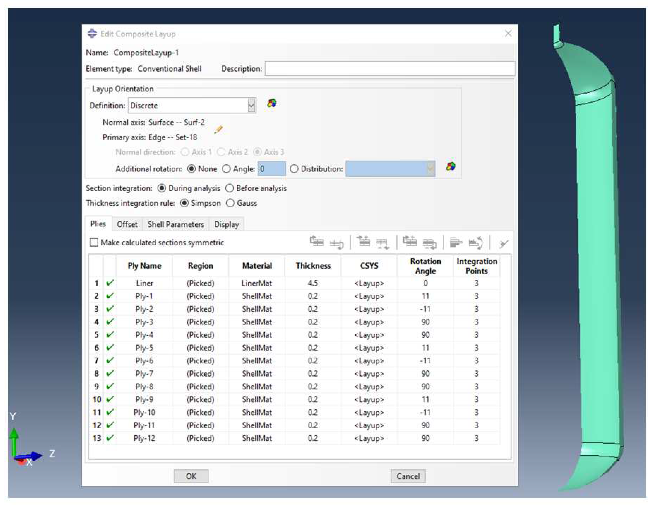
In our model construction using conventional shell elements, we initially considered only the inner dimensions of the liner. Subsequently, we incorporated the filament winding staking by utilizing the Abaqus Composite Layup feature, which also includes the liner. This method requires the input of thickness, material, orientation angle, and the number of integration points for each layer. It is important to note that the liner part is treated as a composite ply with a constant thickness and a zero-degree orientation, as depicted in Figure 2. However, the varying thickness of the liner in the dome region, which was overlooked, will undoubtedly affect its behavior. A critical step in this process is assigning the layup orientation, which applies to all tank simulations. In our case, we used the axial direction as the zero reference orientation. For meshing, we employed S8R - an 8-node doubly thick curved shell element with reduced integration. Despite its simplicity and cost-effectiveness in terms of computational time and resources, this method has some limitations that we will discuss later. Due to its practicality, we utilized this method to simulate both the bare liner and the full tank.

3.3. Simulation Using Continuum Shell Elements

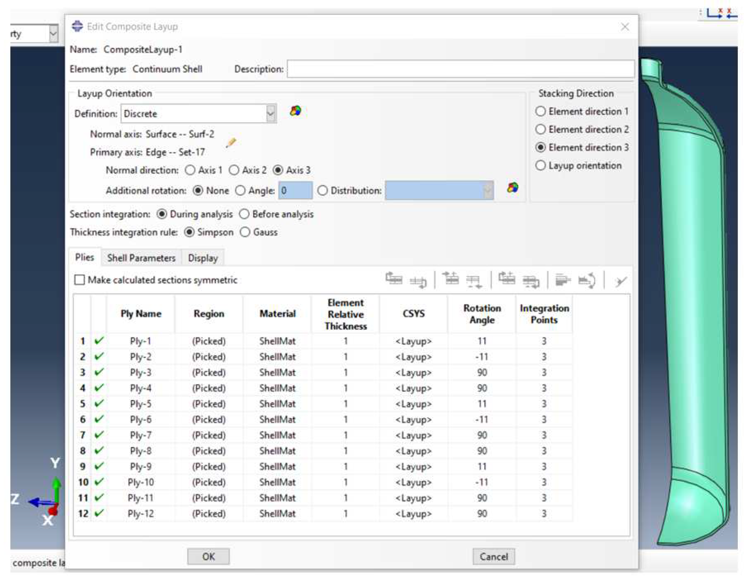
To build a model using continuum shell elements, we divided it into two parts: one for the liner and the other for the composite shell. The first part accurately represents the liner’s geometry, including its varying thickness. The second part represents all the layers combined, accounting for their total thickness. The liner’s properties are introduced as a homogeneous section based on engineering constants and are meshed as a single layer using continuum shell elements. On the other hand, the composite shell properties are introduced using the Abaqus Composite Layup feature, with each of the twelve plies assigned a relative thickness of 1. The same procedure used in conventional shell elements is followed for the stacking sequence and orientation angles, as shown in Figure 3. The composite shell part is meshed using SC8R elements, which are 8-node quadrilateral in-plane general-purpose continuum shells with reduced integration, hourglass control, and finite membrane strains. This method is not only practical and straightforward to implement but also cost-effective in terms of computational time. We utilized this method to simulate both the bare liner and the full tank.

3.4. Simulation Using Mixed Method

This approach is referred to as a mixed method because it integrates the homogenization procedure outlined in Section 2.4 with one of the three previously mentioned simulation methods. Specifically, we first homogenize the composite shell part of the tank using the micro-mechanics method, then treat this part as a single layer with the effective properties obtained. Simulations can be conducted using any of the three previously described methods: conventional shell elements, continuum shell elements, and 3D elements. As a result, the model consists of two layers representing the liner and the homogenized shell in all cases, making it straightforward to implement. However, one clear limitation is the absence of inter- and intra-laminar states in the composite shell. It’s worth noting that the effective properties of the homogenized composite shell are obtained as engineering constants suitable for both the 3D elements model and the continuum shell elements model, as well as an ABD stiffness matrix suitable for the conventional shell elements model.
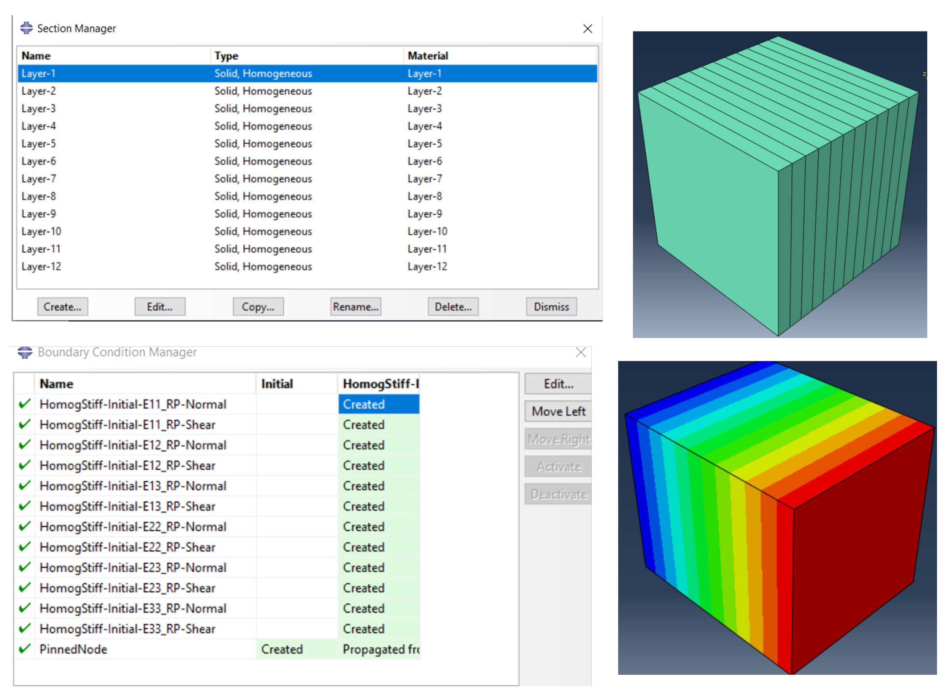
Figure 4 shows the Abaqus-based computational model used to determine the three-dimensional effective properties and the ABD matrix for both the Solid-To-Solid and Solid-To-Shell homogenization scenarios. This model represents a composite with a specific stacking sequence of ( ± 11 , 90 2 )3, as illustrated in Figure 2. Each layer within this sequence has a thickness of 0.2 mm, and the properties associated with these layers are detailed in Table 1. Table 2 reports the three-dimensional effective properties for the Solid-To-Solid homogenization, while Equation (12) provides the upper triangular part of the symmetric ABD matrix corresponding to the Solid-To-Shell homogenization.
ABD = 65924.9 12248.3 8.41842 × 10 4 74100.3 14455.6 555.062 67909.2 6.76931 × 10 5 14455.6 86985.2 44.6329 12491.5 555.062 44.6329 14747.5 114553 22935.2 1110.12 143572 89.2657 23402.1

4. Comparison between Methods and Discussion

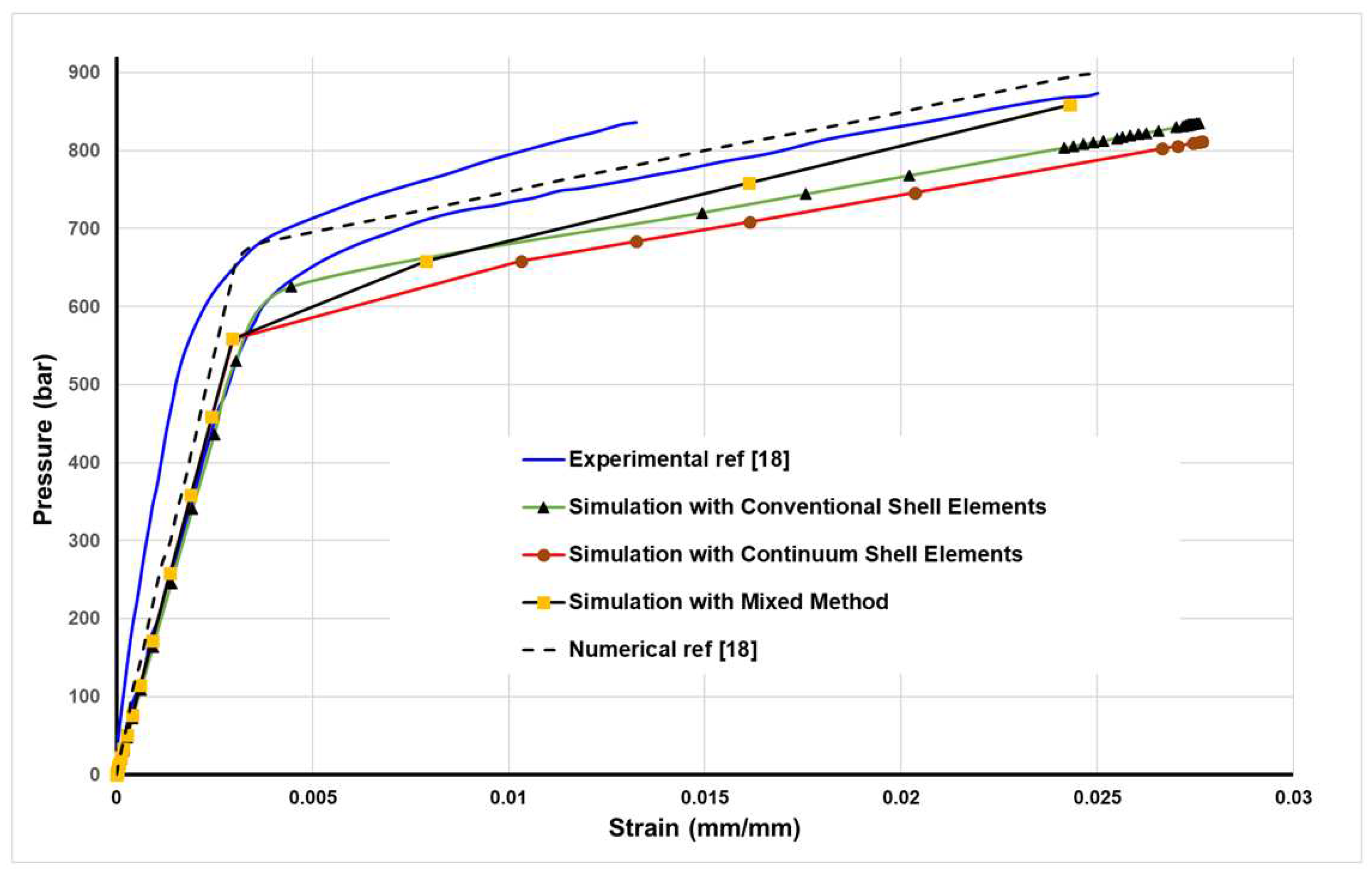
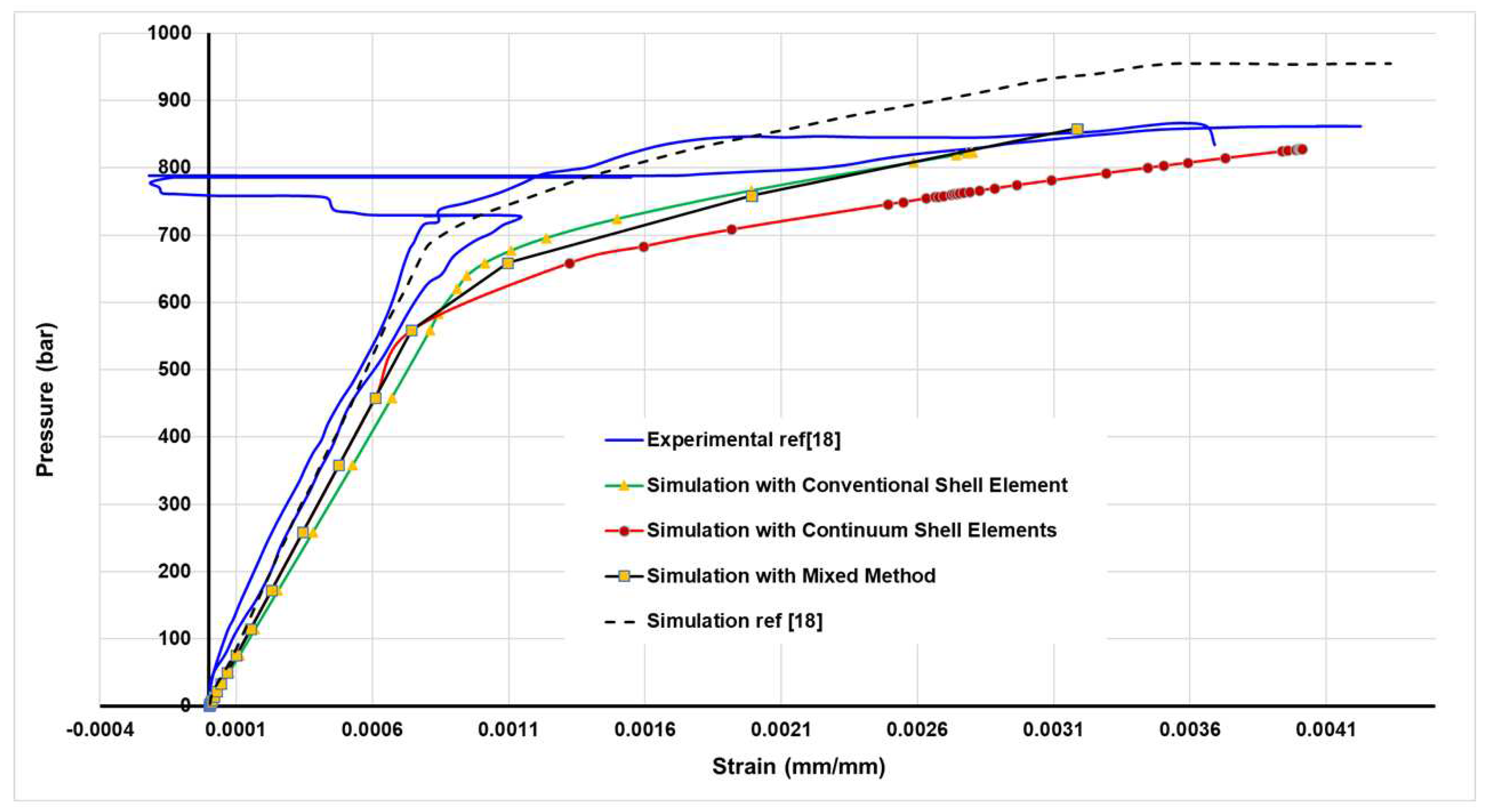
We here explore the mechanical behavior of a cylindrical tank subjected to internal pressure through a comparative analysis of experimental and numerical simulations. Reference [18] is utilized for benchmarking purposes. The tank’s response, in terms of hoop strain versus applied internal pressure at the central cylindrical section, is investigated using a combination of experimental and numerical techniques, see Figure 5. The numerical simulations reveal that our methods tend to underestimate the global stiffness of the tank, leading to an earlier onset of yield compared to experimental results. This discrepancy is attributed to the absence of filament-wound composite interlacement in our simulations as it is well known that the interlacement of the filament bands increases the stiffness of the wound composite. However, the post-yield behavior closely aligns across all curves, indicating successful modeling of the damage phenomenon. Notably, the mixed method deviates from this trend as it does not consider damage in the homogenization process. Among the numerical approaches, the one closest to experimental results employs conventional shell elements in Abaqus, which models the tank as a multilayer body, accounting for both liner and composite shell components. In contrast, the continuum shell elements approach divides the tank into two distinct parts—liner and composite shell—joined by tie contacts.
In this section, the tank’s response, in terms of axial strains versus applied internal pressure is investigated at the central cylindrical section, see Figure 6. Again, our methods tend to underestimate the global stiffness of the tank, leading to an earlier onset of yield compared to experimental results. This is due to the absence of filament-wound composite interlacement as mentioned before. However, our methods’ post-yield behavior closely aligns with the experimental results, indicating successful modeling of the damage phenomenon. Notably, the mixed method and the conventional shell elements methods are the closest. It bears emphasizing that the axial strains obtained with our methods are more accurate than those obtained by FEM in the reference. This comparative study sheds light on the accuracy and limitations of different simulation methods in predicting the mechanical response of composite cylindrical tanks under internal pressure.
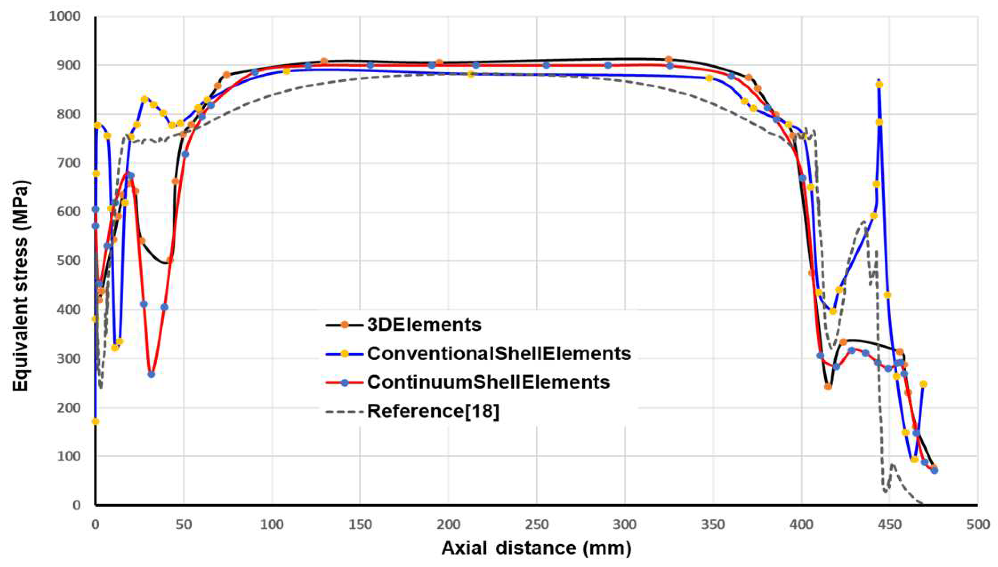
Figure 7 presents a comparative analysis of equivalent stress profiles along the inner surface of a bare liner subjected to a pressure of 700 bars. The comparison is made between results obtained using our simulation methods and those from the numerical approach referenced in the reference. Our method consistently yields higher equivalent stress values than the reference throughout the cylindrical section of the tank. However, all four curves closely align in this region. Notably, significant differences emerge in the dome regions, with distinct trends observed for all methods, although the continuum shell element and 3D element methods exhibit similarity. This divergence can be attributed to the accurate representation of varying dome thickness by the 3D element and continuum shell element methods, in contrast to the conventional element method which assumes a constant dome thickness. Moreover, the front dome experiences more pronounced equivalent stress fluctuations compared to the rear dome, where the conventional shell elements display an exaggerated response due to the constant thickness assumption. This analysis highlights the influence of numerical methods on equivalent stress predictions in the diverse regions of cylindrical tanks, emphasizing the importance of accurately modeling varying thickness profiles, particularly in the dome sections.
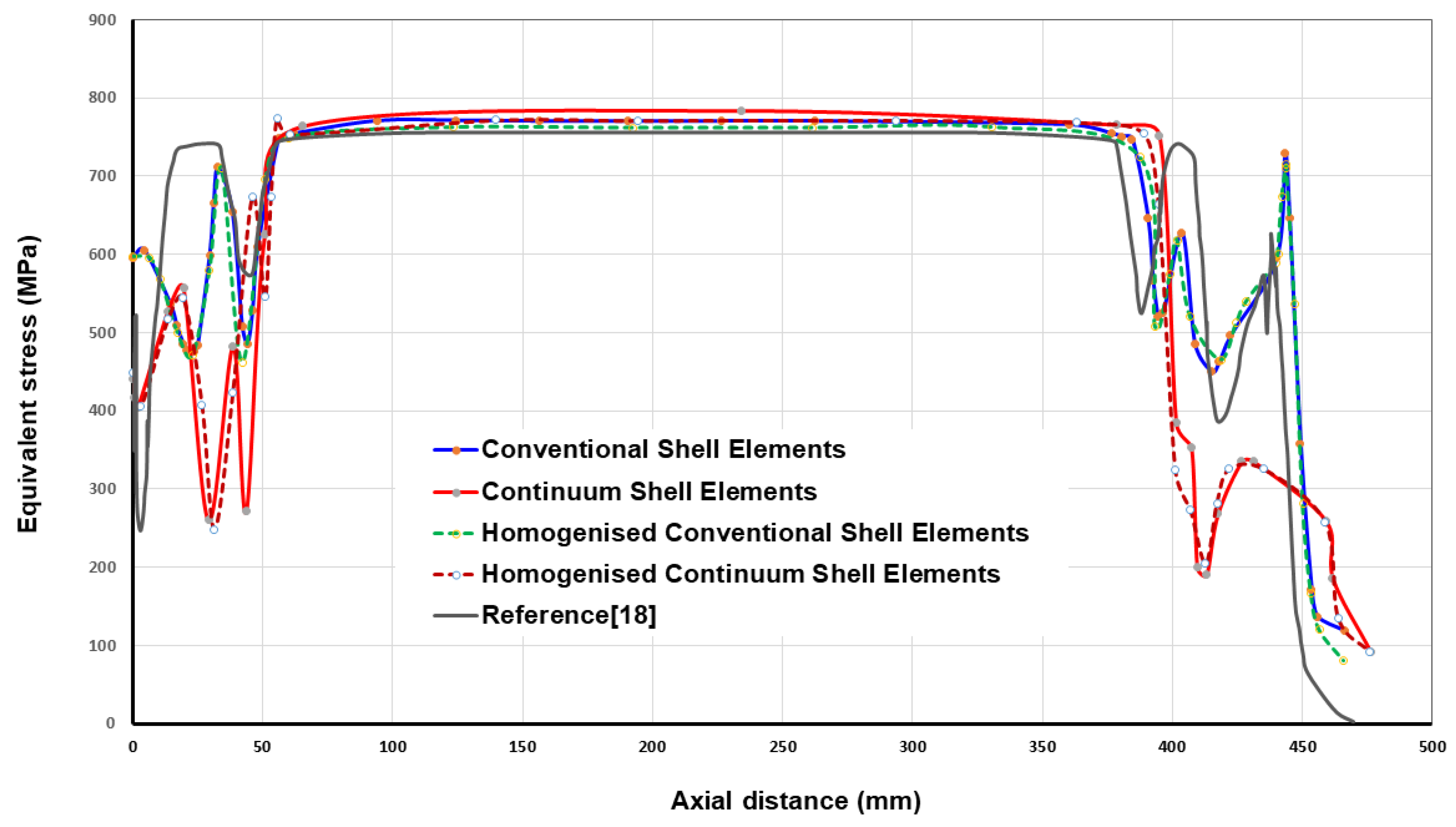
Figure 8 presents a comparative analysis of equivalent stress distributions along the inner surface of the wound liner at 700 bars, employing our developed methods and the numerical approach introduced for comparison. The results reveal striking similarities between our methods and the reference in the cylindrical section of the tank, indicating that the wound liner experiences lower stress levels compared to a bare liner in this region. However, notable disparities emerge in the dome region between all the methods used, displaying a distinct response. Notably, our mixed method incorporating homogenization closely aligns with the method without homogenization, suggesting that homogenization plays a significant role in achieving accurate results. This consistency is observed both in the conventional shell element and continuum shell element analyses, affirming the precision of our homogenization approach. Furthermore, our methods offer enhanced insights into the dome region, surpassing the level of detail provided by the reference approach. The stress trends within the dome regions differ substantially across all methods, with the continuum shell element and mixed homogenized continuum shell element methods standing out as superior choices based on the previously mentioned reasons. It is worth noting that stress fluctuations are more pronounced in the front dome compared to the rear dome, mirroring the behavior observed in the bare liner. In summary, our study showcases the effectiveness of our methods in analyzing the stress distribution along a wound liner at high pressure, particularly in the dome region, where they offer enhanced insights and accuracy.

5. New Design of Type-IV Hydrogen Tank

A notable advancement in pressure vessel technology has been realized through the successful development of composite materials, paving the way for the introduction of type-IV composite pressure vessels. Type-IV vessels represent a significant innovation in this context, constructed entirely from composite reinforcement polymer and featuring a plastic internal liner. However, their status as the lightest option renders them susceptible to damage scenarios, as the plastic liner does not contribute to load-bearing capacity. Among the various challenges associated with type-IV composite pressure vessels, the most critical one is the potential for burst due to laminate failure. Consequently, numerous research endeavors have been initiated to investigate burst pressure behavior and optimize vessel designs. This section aims to extend our understanding by delving into the influence of laminated stacking sequence, orientation angle, and number of plies on burst pressure performance in type-IV composite pressure vessels.
Therefore, we propose the utilization of new materials, specifically high-density polyethylene (HDPE) for the liner and carbon fiber-reinforced epoxy for the composite wound shell. All the necessary property parameters for conducting simulations can be found in Table 3.
In the new tank design, we have maintained the same geometry and stacking arrangement as in the previous comparative study. The critical consideration at this juncture pertains to determining the number of plies required in the new design to withstand a pressure of 1000 bar without experiencing a burst. As tank pressure increases, it can either burst in a safe manner at the cylindrical part or in an unsafe manner at the domes. For the purpose of design optimization, the bursting mode serves as a critical constraint. The burst pressure is determined by identifying the load increment just before the radial and/or axial displacements start to diverge. A safe burst occurs when the radial displacement continues to increase under constant pressure at the cylindrical part of the tank, while an unsafe burst happens when the axial displacement increases at the dome extremity under constant pressure.
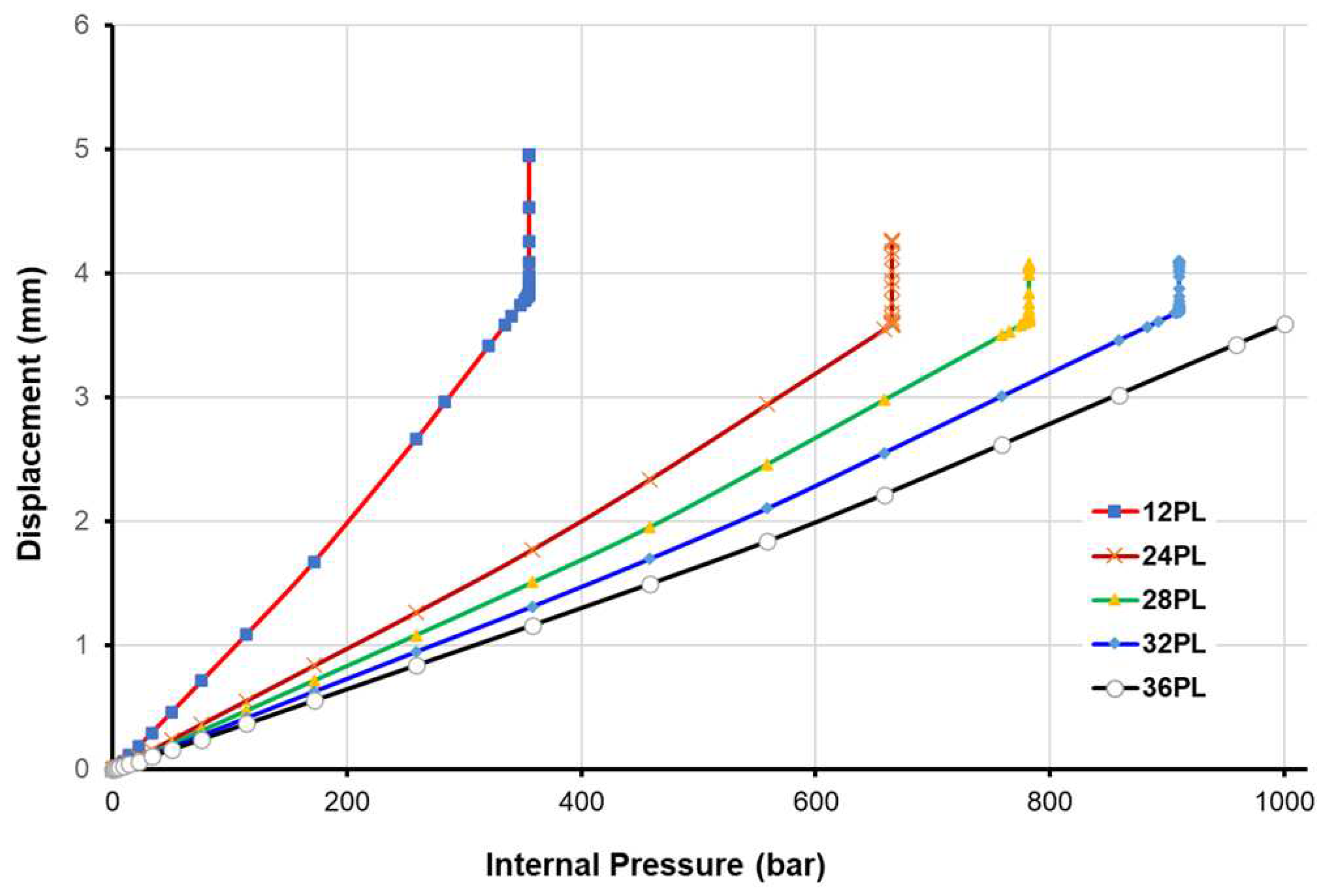
All of these phenomena eventually lead to simulation divergence, which halts the calculation process. Initially, we maintained the same stacking configuration and number of plies as before (12 plies), to model the pressure at which the new design would burst. In Figure 9, we can observe the displacement response as a function of internal pressure at the dome extremity for each number of stacking plies. One can notice from the graph that the tank can withstand only 355 bar when we maintain the number of 12 plies (constant pressure with increasing displacement). We applied this criterion with varying numbers of plies, and whenever this divergence occurred (criterion is satisfied), we increased the layup by an additional 4 plies ( ± 11 , 90 2 ) and launched a new simulation. Figure 9 illustrates how the burst pressure is shifted with different stacking configurations until we achieve a condition where no divergence occurs. Consequently, we can assert that the tank can endure a pressure of 1000 bar when using 36 plies, resulting in a composite shell thickness of 7.2 mm. Noteworthy that the burst occurs every time in the dome (unsafe mode).
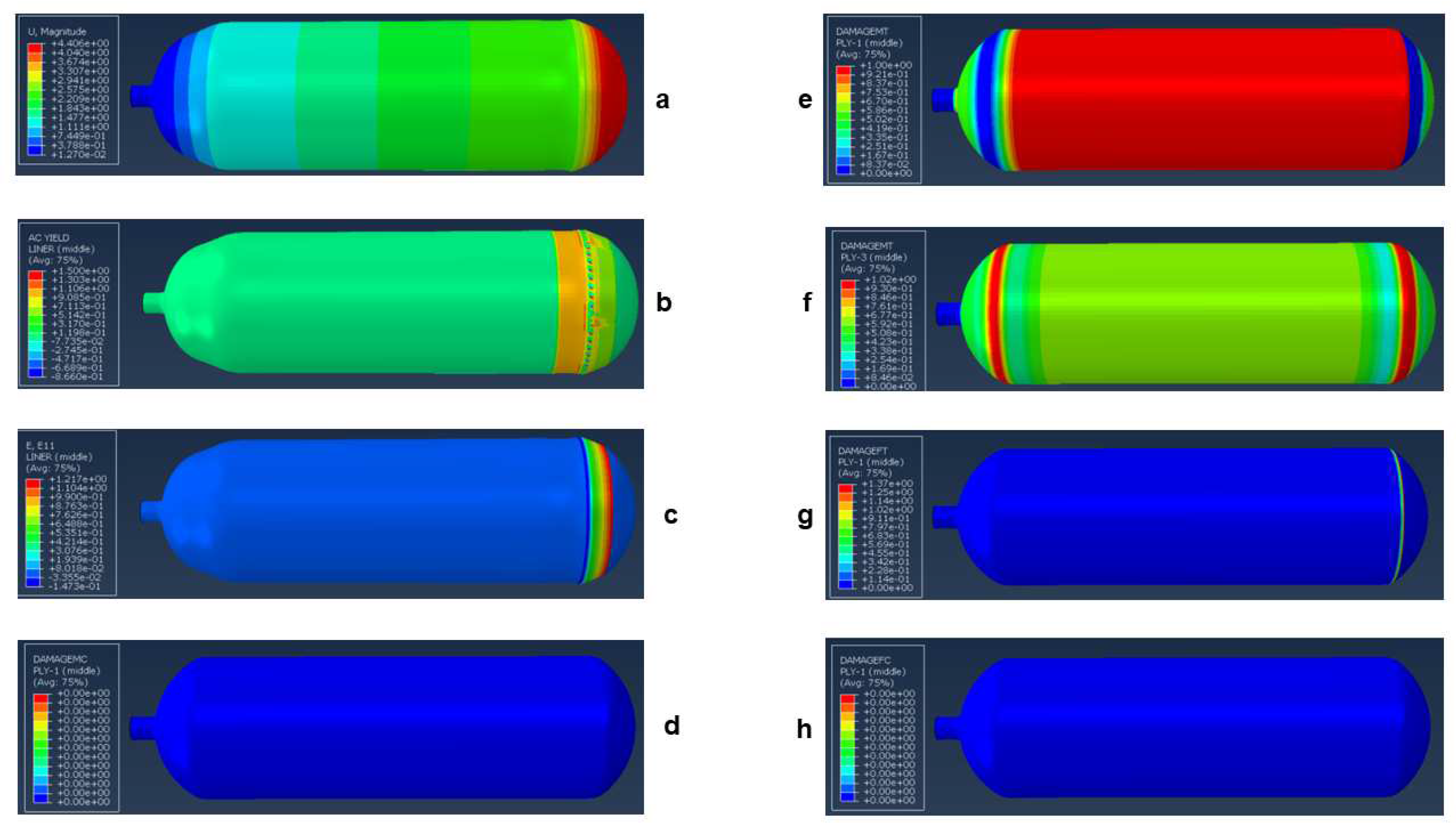
Figure 10 depicts the tank behavior and the damage response based on the Hashin criterion in both the fiber and the matrix for a composite shell of 24 plies, the results are taken mainly at the liner, at the first ply (orientation 11) and the third ply (orientation 90).
Finally, by maintaining the same number of 36 plies but altering the filament angle to ( ± 55 )18, we found that the tank can only withstand a maximum of 140 bar. This highlights the significance of stacking sequence and pattern as key parameters influencing the tank’s burst pressure, emphasizing the need for optimization techniques to enhance the tank’s performance.

6. Concluding Remarks

  • In this study, we presented a comparative analysis of various numerical methods for modeling composite pressure vessels, aiming to provide a comprehensive understanding of their performance. The methods under scrutiny include finite element analysis in Abaqus with conventional shell elements, continuum shell elements, three-dimensional solid elements, and homogenization approaches for multilayered composite pressure vessels. Through a systematic comparison, this research offers insights into the strengths and limitations of each method.
  • The findings of this study indicate that three-dimensional solid elements yield the highest accuracy in modeling composite pressure vessels. However, their practicality diminishes as the number of layers in the composite increases. Following closely are the continuum shell elements, which strike a balance between accuracy and computational efficiency due to their intermediate nature, combining features of both 3D and conventional shell elements. Meanwhile, the method relying solely on conventional shell elements proves accurate for specific applications but lacks universality.
  • Moreover, this research underscores the significance of the homogenization technique, particularly for damage-free applications, as it consistently delivers highly accurate results.
  • In the second part of the paper, a new design dedicated to type-IV hydrogen tank, composed of carbon fibers, epoxy resin, and a high-density polyethylene (HDPE) liner, is proposed. The study concentrates on predicting damage onset and behavior within the tank and burst pressure prediction. With this new design, we demonstrated that the tank can endure a pressure of 1000 bar when using 36 plies, resulting in a composite shell thickness of 7.2 mm.

Author Contributions

Lyazid Bouhala: Conceptualization, Methodology, Software development, Investigation, Writing - Original draft preparation, Project acquisition and administration. Yao Koutsawa: Conceptualization, Methodology, Investigation, Writing - Original draft preparation. Argyrios Karatrantos: Writing - Reviewing and Editing. Claus Bayreuther: Reviewing and Editing.

Data Availability Statement

The raw/processed data required to reproduce these findings cannot be shared at this time as the data also forms part of an ongoing study.

Acknowledgments

This research was funded in whole, or in part, by the Luxembourg National Research Fund (FNR), grant reference [«INTER/MERA22/17557282/HYMOCA»]. For the purpose of open access, the author has applied a Creative Commons Attribution 4.0 International (CC BY 4.0) license to any Author Accepted Manuscript version arising from this submission. The authors would also like to express their gratitude for the support received from the Sustainable Composite Materials & Manufacturing (SCMM) Innovation Centre.

Conflicts of Interest

The authors declare that they have no known competing financial interests or personal relationships that could have appeared to influence the work reported in this paper.

References

  1. J. Humberto, J. Almeida, L. St-Pierre, Z. Wang, M. L. Ribeiro, V. Tita, S. C. A. f, S. G. Castro, Design, modelling, optimization, manufacturing, and testing of variable-angle filament-wound cylinders, Composites Part B 225 (2021) 109224.
  2. Y. Regassa, J. Gari, H. G. Lemu, Composite overwrapped pressure vessel design optimization using numerical method, J. Compos. Sci. 6 (2022) 229. [CrossRef]
  3. Q. Zhanga, H. Xua, X. Jiab, L. Zua, S. Chenga, H. Wanga, Design of a 70 mpa type iv hydrogen storage vessel using accurate modelling techniques for dome thickness prediction, Composite Structures 236 (2020) 111915.
  4. K. C. Jois, M. Welsh, T. Gries, J. Sackmann, Numerical analysis of filament wound cylindrical composite pressure vessels accounting for variable dome contour, J. Compos. Sci. 5 (2021) 56. [CrossRef]
  5. N. Zhang, S. Gao, M. Song, Y. Chen, X. Zhao, J. Liang, J. Feng, A multiscale study of cfrp based on asymptotic homogenization with application to mechanical analysis of composite pressure vessels, Polymers 14 (2022) 2817. [CrossRef]
  6. H. Kang, P. He, C. Zhang, Y. Dai, H. Lv, M. Zhang, D. Yang, Stress–strain and burst failure analysis of fibre wound composite material high-pressure vessel, Polymers and Polymer Composites 29(8) (2021) 1291–1303.
  7. H. Wang, S. Fu, Y. Chen, L. Hua, Thickness-prediction method involving tow redistribution for the dome of composite hydrogen storage vessels, Polymers 14 (2021) 902. [CrossRef]
  8. S. Sapre, K. Pareek, M. Vyas, Investigation of structural stability of type iv compressed hydrogen storage tank during refueling of fuel cell vehicle, Energy Storage 2 (2020) 150. [CrossRef]
  9. A. V. Daniele Landi, S. Borriello, M. Scafà, M. Germani, A methodological approach for the design of composite tanks produced by filament winding, Computer-Aided Design and Applications 17 (6) (2020) 1229–1240. [CrossRef]
  10. M. A. Jebeli, M. Heidari-Rarani, Development of abaqus wcm plugin for progressive failure analysis of type iv composite pressure vessels based on puck failure criterion, Engineering Failure Analysis 131 (2022) 105851. [CrossRef]
  11. J. H. S. A. Jr., L. St-Pierre, Z. Wang, M. L. Ribeiro, V. Tita, S. C. Amico, S. G. Castro, Design, modelling, optimization, manufacturing and testing of variable-angle filament-wound cylinders, Composites Part B 225 (2021) 109224.
  12. O. Kartav, S. Kangal, K. Yücetürk, M. Tanoglu, E. Aktas, H. S. Artem, Development and analysis of composite overwrapped pressure vessels for hydrogen storage, Journal of Composite Materials 0 (2021) 1–15. [CrossRef]
  13. M. Zhang, H. Lv, H. Kang, W. Zhou, C. Zhang, A literature review of failure prediction and analysis methods for composite high-pressure hydrogen storage tanks, International Journal of Hydrogen Energy 44 (2019) 25777–25799. [CrossRef]
  14. B. N. Nguyen, H. S. Roh, D. R. Merkel, K. L. Simmons, A predictive modelling tool for damage analysis and design of hydrogen storage composite pressure vessels, International Journal of Hydrogen Energy 46 (2021) 20573–20585. [CrossRef]
  15. R. Moradi, K. M. Growth, Hydrogen storage and delivery: Review of the state-of-the-art technologies and risk and reliability analysis, International Journal of Hydrogen Energy 44 (2019) 12254–12269.
  16. A. J. Modesto, R. Birgul, R. J. Werlink, F. N. Catbas, Damage detection of composite overwrapped pressure vessels using arx models, International Journal of Pressure Vessels and Piping 192 (2021) 104410. [CrossRef]
  17. L. W. Kaite Guo, J. Xiao, M. Lei, S. Wang, C. Zhang, X. Hou, Design of winding pattern of filament wound composite pressure vessel with unequal openings based on non-geodesics, Journal of Engineered Fibers and Fabrics 15 (2020) 1–17. [CrossRef]
  18. S. Kangal, O. Kartav, M. Tanoglu, E. Aktas, H. S. Artem, Investigation of interlayer hybridization effect on burst pressure performance of composite overwrapped pressure vessels with load-sharing metallic liner, Journal of Composite Materials 54 (7) (2020) 961–980. [CrossRef]
  19. A. Rohatgi, Webplotdigitizer: Version 4.6 (2022).URL https://automeris.
  20. L. Bouhala, A. Makradi, S. Belouettar, H. Kiefer-Kamal, P. Fréres, Modelling of failure in long fibres reinforced composites by xfem and cohesive zone model, Composites: Part B 55 (2013) 352–361.
  21. L. Bouhala, Q. Shao, Y. Koutsawa, A. Younes, P. Núnez, A. Makradi, S. Belouettar, An xfem crack-tip enrichment for a crack terminating at a bi-material interface, Engineering Fracture Mechanics 102 (2013) 51–64. [CrossRef]
  22. Dassault Systèmes, Micromechanics Plugin for Abaqus/CAE, Version 1.18, Dassault Systèmes Simulia Corp., United States, 2022. [CrossRef]
  23. W. L. Azoti, A. Tchalla, Y. Koutsawa, A. Makradi, G. Rauchs, S. Belouettar, H. Zahrouni, Mean-field constitutive modeling of elasto-plastic composites using two (2) incremental formulations, Composite Structures 105 (2013) 256–262. [CrossRef]
  24. L. Bouhala, Y. Koutsawa, A. Makradi, S. Belouettar, An advanced numerical method for predicting effective elastic properties of heterogeneous composite materials, Composite Structures 117 (1) (2014) 114–123. [CrossRef]
  25. Dassault Systèmes, User’s Manual, Version 2022, Dassault Systèmes Simulia Corp., United States, 2022.
  26. I. Lapczyk, J. A. Hurtado, Progressive damage modeling in fiber-reinforced materials, Composites Part A: Applied Science and Manufacturing 38 (11) (2007) 2333–2341. [CrossRef]
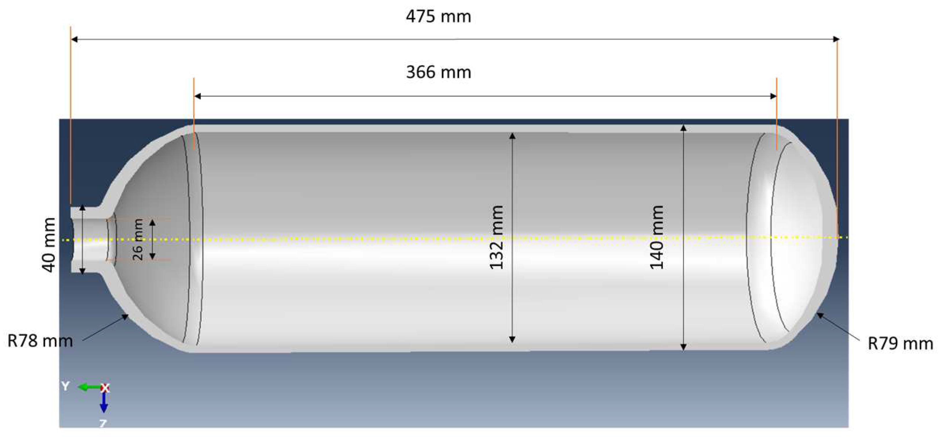
Figure 1. Geometry of the bare liner used for comparison from reference [18]
Preprints 93329 g001
Figure 2. Abaqus conventional shell element CompositeLayup feature overview
Preprints 93329 g002
Figure 3. Abaqus continuum shell element CompositeLayup feature overview
Preprints 93329 g003
Figure 4. Abaqus model for both Solid-to-Solid and Solid-to-Shell homogenization scenarios
Preprints 93329 g004
Figure 5. Comparison between the hoop strain Vs. the applied internal pressure obtained with conventional shell elements, continuum shell elements, mixed method, and the experimental and numerical results of the reference
Preprints 93329 g005
Figure 6. Comparison between the axial strain Vs. the applied internal pressure obtained with conventional shell elements, continuum shell elements, mixed method, and the experimental and numerical results of the reference
Preprints 93329 g006
Figure 7. Comparison of equivalent stress vs. axial distance along the inner surface of the bare liner at 700 bar using conventional shell elements, continuum shell elements, and 3D elements
Preprints 93329 g007
Figure 8. The equivalent stress vs. axial distance along the inner surface of the wound liner at 700 bar using conventional shell elements, continuum shell elements, homogenized conventional shell elements, and homogenized continuum shell elements
Preprints 93329 g008
Figure 9. The axial displacement at the extremity of the back dome vs. the internal pressure for different numbers of plies using conventional shell elements model
Preprints 93329 g009
Figure 10. The tank response simulation using conventional shell elements model at failure for a stacking of 24 plies: a) magnitude of the displacement, b) yield response in the polymeric liner, c) axial strain in the liner, d) compression damage of the matrix in the first ply, e) tensile damage of the matrix in the first ply, f) damage of the matrix in tension at the third ply, g) damage of the fiber in tension at the first ply, h) damage of the fiber in compression at the first ply
Preprints 93329 g010
Table 1. Orthotropic elastic properties and stress limits of glass fiber reinforced epoxy-based composites and elastic-plastic properties of the steel liner .
Symbol Description Unit Value
Glass fiber/epoxy composite
E 1 Longitudinal (fiber dominated) modulus MPa 38,500
E 2 = E 3 Transverse (matrix dominated) modulus MPa 16,500
ν 12 Poisson’s ratio in-plane) - 0.27
ν 23 Poisson’s ratio (planes 2-3) - 0.28
G 12 = G 13 In-plane shear modulus MPa 4700
G 23 Shear modulus (planes 2-3) MPa 5000
X T Longitudinal (fiber dominated) Tensile strength MPa 1250
X C Longitudinal (fiber dominated) Compressive strength MPa -650
Y T Transverse (matrix dominated) Tensile strength MPa 36
Y C Transverse (matrix dominated) Compressive strength MPa -165
S L In-plane shear strength MPa 86
G f Fracture energy of the fiber N/mm 12.5
G m Fracture energy of the matrix N/mm 1
Steel liner (SL)
ESL Young’s modulus MPa 205,000
ν SL Poisson’s ratio - 0.3
σ y , SL Yield strength MPa 743
E tan , SL Bilinear isotropic hardening tangent modulus MPa 2600
Table 2. Three-dimensional effective properties corresponding to the Solid-To-Solid homogenization scenario
E1 (MPa) E2 (MPa) E3 (MPa) ν 12 (-) ν 13 (-) ν 23 (-) G12 (MPa) G13 (MPa) G23 (MPa)
26548.24 27347.34 17343.40 0.180 0.344 0.339 5204.77 4700 4700
Table 3. Orthotropic elastic properties and stress limits of carbon fiber reinforced epoxy-based composites and elastic-plastic properties of the high-density polyethylene (HDPE) liner [18,25].
Symbol Description Unit Value
Carbon fiber/epoxy composite
E 1 Longitudinal (fiber dominated) modulus MPa 141,000
E 2 = E 3 Transverse (matrix dominated) modulus MPa 11,400
ν 12 Poisson’s ratio in-plane) - 0.28
ν 23 Poisson’s ratio (planes 2-3) - 0.40
G 12 = G 13 In-plane shear modulus MPa 5000
G 23 Shear modulus (planes 2-3) MPa 3080
X T Longitudinal (fiber dominated) Tensile strength MPa 2080
X C Longitudinal (fiber dominated) Compressive strength MPa -1250
Y T Transverse (matrix dominated) Tensile strength MPa 60
Y C Transverse (matrix dominated) Compressive strength MPa -290
S L In-plane shear strength MPa 110
G f Fracture energy of the fiber N/mm 78
G m Fracture energy of the matrix N/mm 1
Isotropic elastic properties for the high-density polyethylene liner (HDPE) [25]
E HDPE Young’s modulus MPa 903.114
ν HDPE Poisson’s ratio - 0.39
Isotropic plastic hardening data for the HDPE liner material  [25]
Yield stress (MPa ) 8.618 13.064 16.787 18.476 20.337 24.543 26.887
Plastic strain (-) 0 0.007 0.025 0.044 0.081 0.28 0.59
Disclaimer/Publisher’s Note: The statements, opinions and data contained in all publications are solely those of the individual author(s) and contributor(s) and not of MDPI and/or the editor(s). MDPI and/or the editor(s) disclaim responsibility for any injury to people or property resulting from any ideas, methods, instructions or products referred to in the content.
Copyright: This open access article is published under a Creative Commons CC BY 4.0 license, which permit the free download, distribution, and reuse, provided that the author and preprint are cited in any reuse.
Prerpints.org logo

Preprints.org is a free preprint server supported by MDPI in Basel, Switzerland.

Subscribe

© 2024 MDPI (Basel, Switzerland) unless otherwise stated