1. Introduction
Additive building manufacturing is a process of building parts that is based on creating a physical object from an electronic model by adding material, typically layer by layer. Additive technologies are widely used in the construction of buildings and structures [
1].
A significant part of the world’s energy consumption is spent on building maintenance. Therefore, the energy-efficiency of the buildings has become a key priority for solving energy-saving issues. Additive technology allows improving the quality and reliability of a construction structure by excluding human errors, significantly reducing the cost of constructing buildings with unique architecture [
2,
3]. The thermal properties of 3D printing enclosing structures have a significant impact on the energy efficiency of buildings. The research of thermal behavior and the development of solutions for increasing the energy efficiency of enclosing structures created using additive technologies are necessary for reducing energy costs consumed for heating and cooling of buildings and improving the quality of the buildings’ internal environment [
4].
The buildings envelope constructed by additive technology are classified according to the purpose, the character of static work, the homogeneity of the material, the placement of insulation in the cavities of the structure, the sequence of insulation placement, the material, reinforcement, and the presence of a rigidity diaphragm [
5].
According to the purpose, structures are divided into external ones that protect the premises from natural climatic conditions and internal ones that meet the constructive and ecological, sanitary, and hygienic operational, aesthetic, and economic requirements of the object. According to the character of static work, the structures can be classified as load bearing, self-supporting, and non-load bearing, performing the role of partitions in the room. The additive building structure can be classified as homogeneous (made of one material) and non-homogeneous (composed of several materials). Non-homogeneous walls can have partial filling and consist not only of one material but also can have closed air cavities. The enclosing structure can be divided into a frame and inner filling.
The thermal insulation materials used for the additive exterior wall are polystyrene foam; extruded polystyrene foam; urethane foam; mineral wool; liquid thermal insulation; aerogel materials. The aerogel is rarely used as a thermal insulation material the additive building constructions [
6].
An aerogel is a nano-porous insulation material that has unique properties—extremely low thermal conductivity, superior flexibility, compression resistance and the most promising superinsulation systems. The thermal conductivity of thermal insulation materials is one of the most important parameters to increase energy efficiency of the buildings. Aerogels consist of globules, several nanometers in size, interconnected by an extensive network of mesoporous, which are filled with air [
7]. The pore size exceeds the size of the clusters themselves by ten or more times. The aerogel is a nanostructured material with high porosity and excellent thermal insulation properties [
8,
9]. A significant disadvantage is the high cost of manufacturing and application. Nevertheless, studies of thermophysical properties and properties of aerogel materials have been relevant research topics in the last few years. Testing and development of these insulation materials are very important for both manufacturers and designers. Therefore, studies of thermal properties are extremely important [
8].
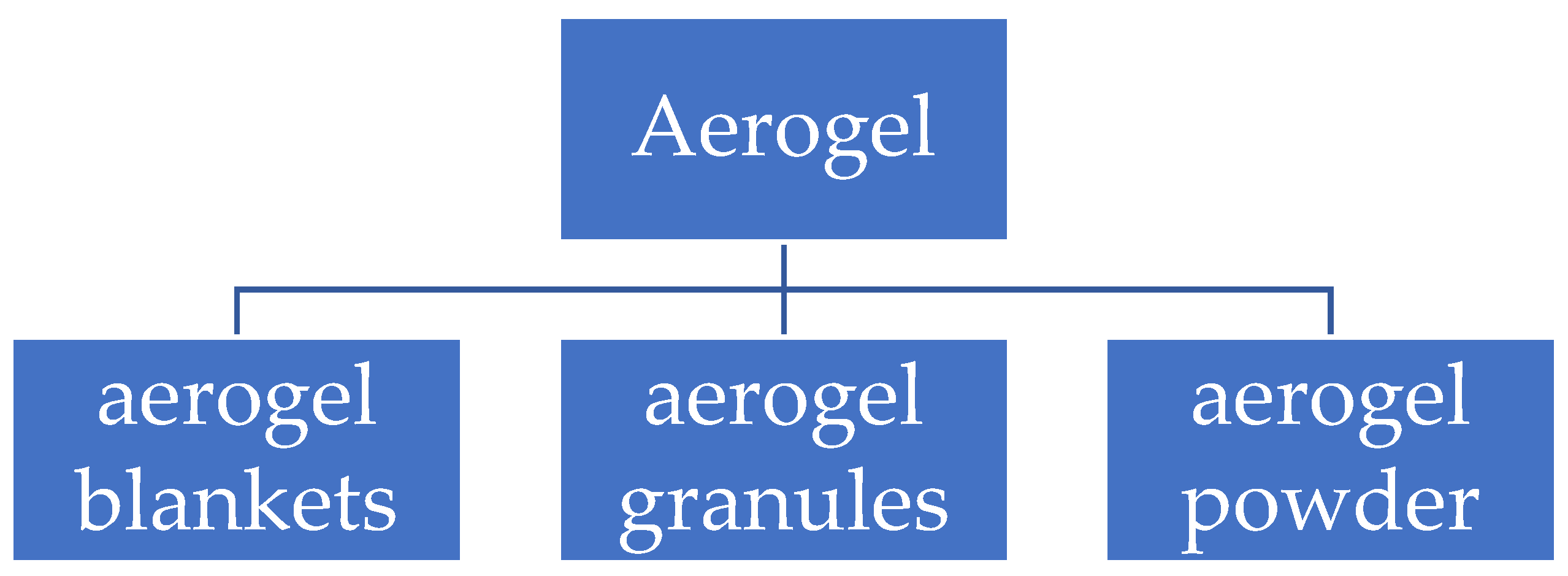
The applications aerogels can be used as aerogel granules, powder, and aerogel blankets (
Figure 1).
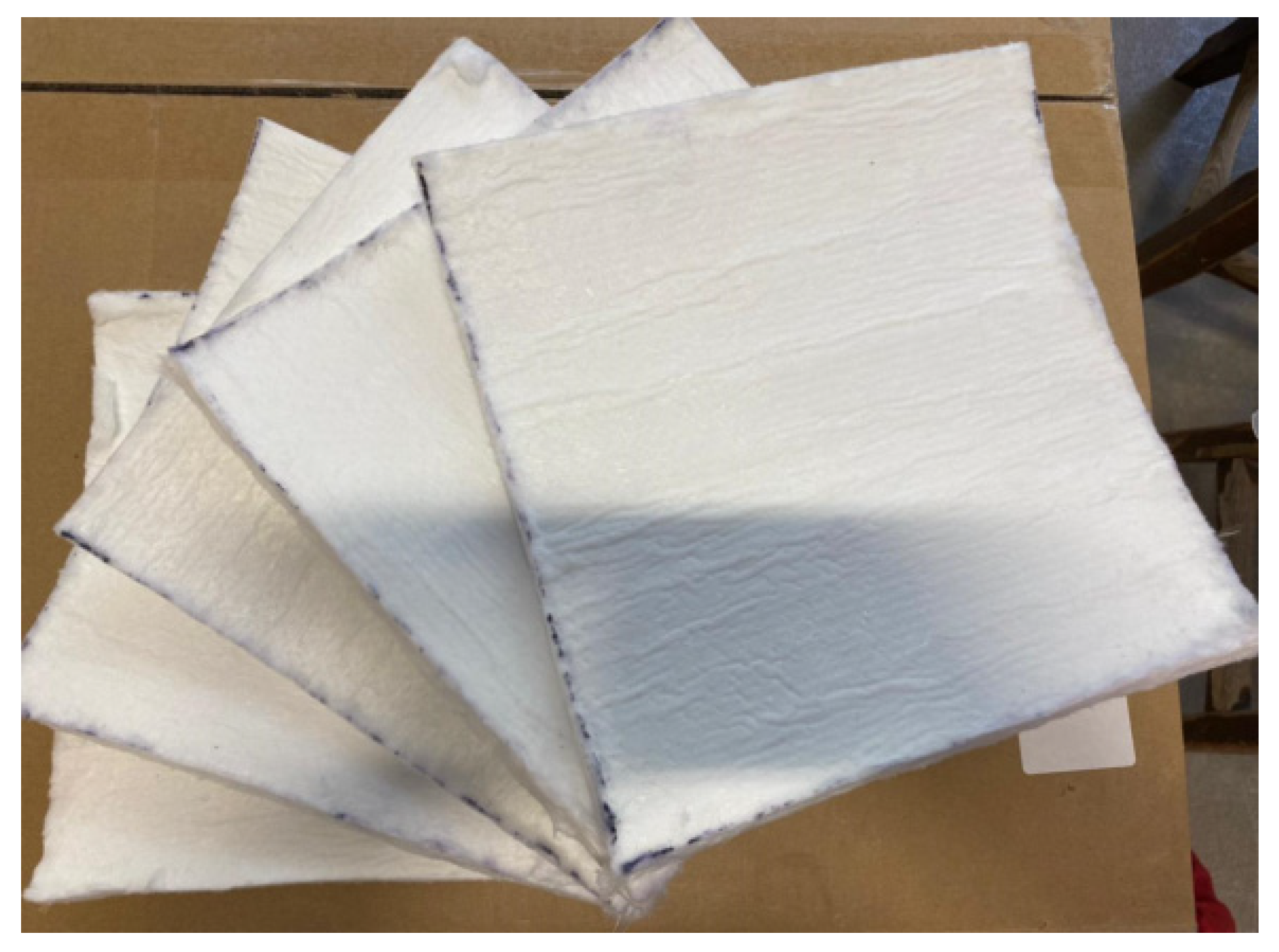
Aerogel blankets are a based innovative insulation material based on silica aerogel produced from fiberglass (
Figure 2).
The authors investigated the thermal properties of aerogel blankets [
11]. The paper obtained the temperature dependence of the thermal conductivity of aerogel blanket samples in the range from 0 to 65 ° C and established a change of about 18%. The authors investigated a thermal conductivity, the effect of temperature on the change in specific heat from 0 to 65 °C. Based on the measured thermal conductivity and specific heat capacity, thermal conductivity, heat transfer is obtained. The results of the study showed that the thickness can have only a negligible effect on thermal conductivity.
The paper presents a theoretical and experimental study of the thermal conductivity of aerogel blanket. The authors presented a model that considers all the heat transfer mechanisms. The authors carried out an analytical calculation of the change in thermal conductivity depending on temperature; the model was verified with experimental data. Using the proposed model, parametric studies were carried out to study the effect of the total porosity and thermal conductivity of fibers on the effective thermal conductivity of aerogel blanket. [
12]
The research reported the results of thermal conductivity behavior of aerogel-enhanced blankets. The authors presented comparative thermal characterization results of aerogel blankets and established the thermal conductivity as 0.013 W/ (m K). The authors developed and presented some new aerogel-enhanced blankets [
13,
14,
15].
The authors present a study of two types of aerogel blanket: with a fiberglass web and with a polyethylene terephthalate fiber web. The results of calculations showed that aerogel coatings have low thermal conductivity (0.015 W m−1 K−1) and hydrophobic properties. [
16]
The aerogel blanket has a wide range of applications in construction [
17]:
Insulation of building facades to reduce cold bridge and energy costs.
Noise insulation of internal walls. The speed is up to 70 m/s (the minimum speed of sound propagation through the material), so it acts as a sound insulation system, and its minimum thickness allows increasing the saleable area.
Insulation of internal walls. Due to the small thickness of the material, it is suitable for cladding any internal walls, partitions, corners, for local elimination of freezing, to prevent condensation, the appearance of mold.
Thermal insulation of the floors.
Insulation of window and door openings.
Thermal insulation of saunas and baths.
Thermal insulation of pipes etc.
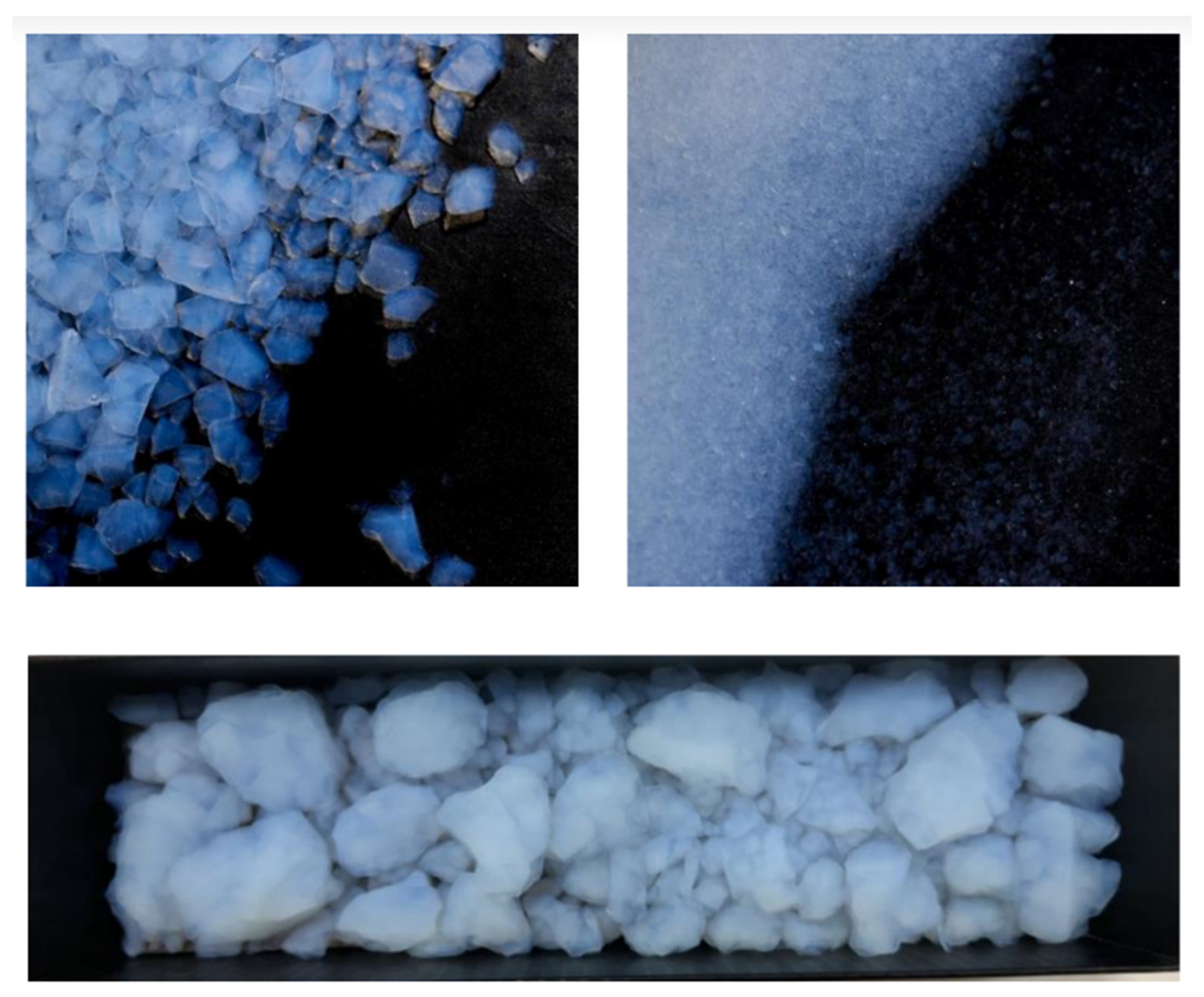
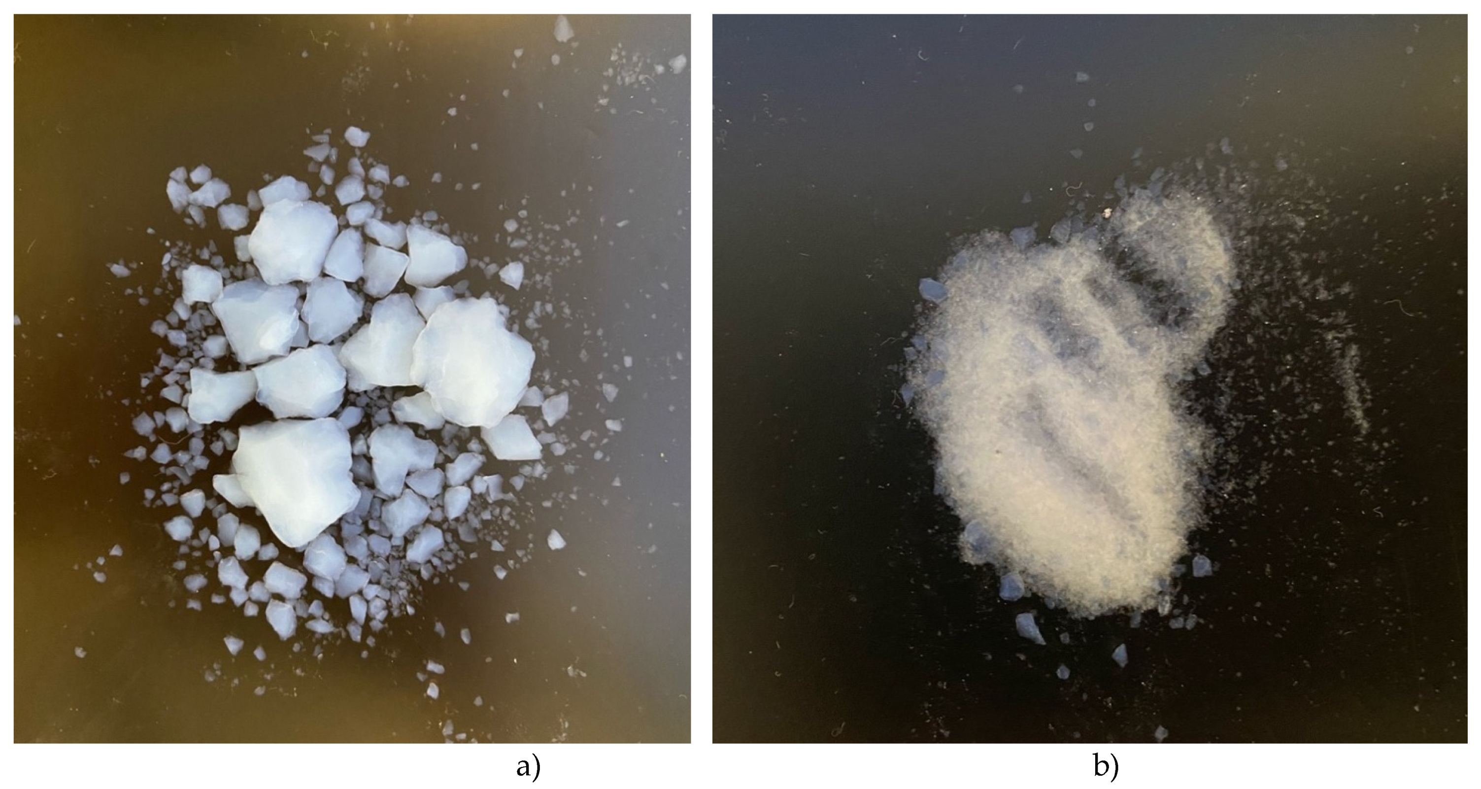
Aerogel powder and granules also used as components of insulation solutions and building materials (
Figure 3). Typically, concrete has a high thermal conductivity ranging from 1.7 to 2.5 W/ (m·K), therefore it requires insulation layers for standard insulating properties. Therefore, building mixtures and concrete with aerogel powder or granules are being developed, which ensure sufficient compressive strength and good thermal insulation. As the amount of aerogel in the mixture increases the thermal conductivity decreases linearly [
18].
The experimental results of thermal performance of aerogel granules into the cavity of double-glazing units are presented in the study [
19]. The results indicate that the particle size of the used aerogel granules influences the optical and thermal properties of the glazing unit. Compared to standard double glazing, double-glazed windows with large aerogel granules (particle size 3-5mm) achieve a 58% reduction in heat loss and a 38% decrease in light transmittance. For a glazing unit with aerogel granules (particle size <0.5mm), the reduction amounts to 63% in terms of heat loss, but as much as 81% in terms of light transmittance.
The authors of this study have developed a synthesis method for silica powders and granules. The process involves the direct hydrophobization of silica aerogel in a diluted organic solution of trimethylchlorosilane, which acts as the phase separation inducer, followed by subsequent drying at atmospheric pressure. This approach allows for the collection and drying of gels at atmospheric pressure without the need for the solvent replacement phase typical in traditional methods. The silica aerogel in the form of powder and granules, obtained by the above method, has a specific surface area of up to 756.0 m2/g, thermal conductivity of up to 0.0164 W/(m·K), and a variable density from 47.6 to 120.0 mg/cm3. Overall, the proposed method represents a simple and economical technique to produce high-quality silica aerogel powders and granules. The obtained aerogels could be applicable in thermal insulation, environmental restoration, adsorption, and other areas [
20,
21].
In this study, the impact of aerogel granule size on the solar light transmittance coefficient was investigated. The energy characteristics of the glazing system with different sizes of aerogel granules and different filler thickness were evaluated under various climatic conditions. The study revealed that the use of aerogel granules with a diameter of 1 mm and a layer thickness of 16 mm can reduce heat losses by 22% when facing the horizon and by 10% when facing east or west in hot summer and cold winter conditions. The results also showed that the use of aerogel granules can reduce the heat increase by 17.36% throughout the year in climatic conditions with a hot summer and warm winter. It was also noted that changing the size of aerogel granules and the thickness of the filler does not make significant changes to the energy characteristics of the aerogel glazing system when facing north [
22].
A literature review showed insufficient quantity of experimental and numerical data and research on the aerogel application for the additive manufacturing of energy efficient buildings. The goal of this study is experimental and numerical assessment on the thermal performance of aerogel-enhanced building structure.
This paper provides the state-of-the-art of aerogel applications for the additive manufacturing of energy efficient buildings.
3. Results and Discussion
3.1. Measurement results of thermal performance of aerogel-enhanced building structure
3.1.1. Experimental results of thermal performance of aerogel-enhanced building structure
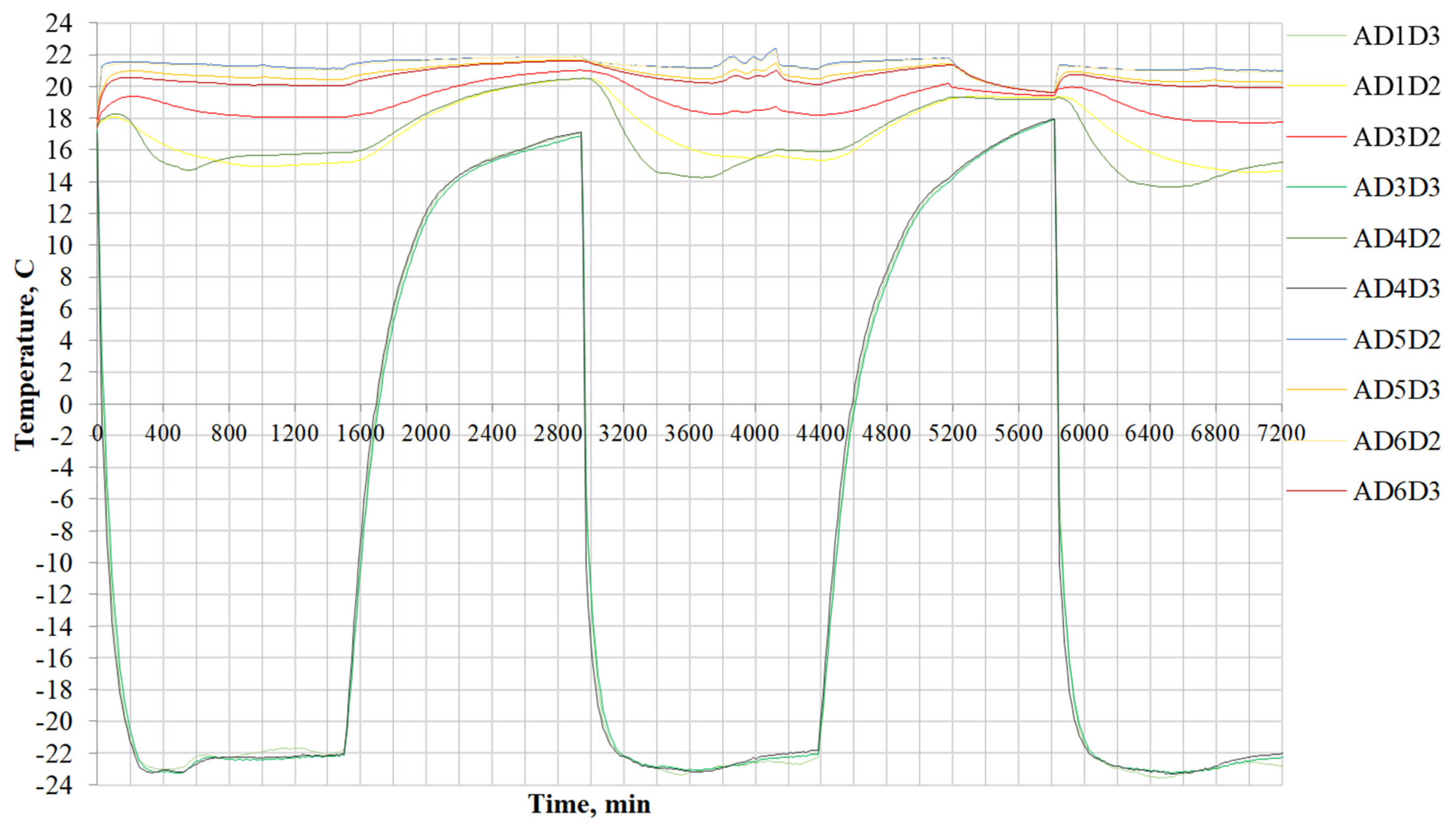
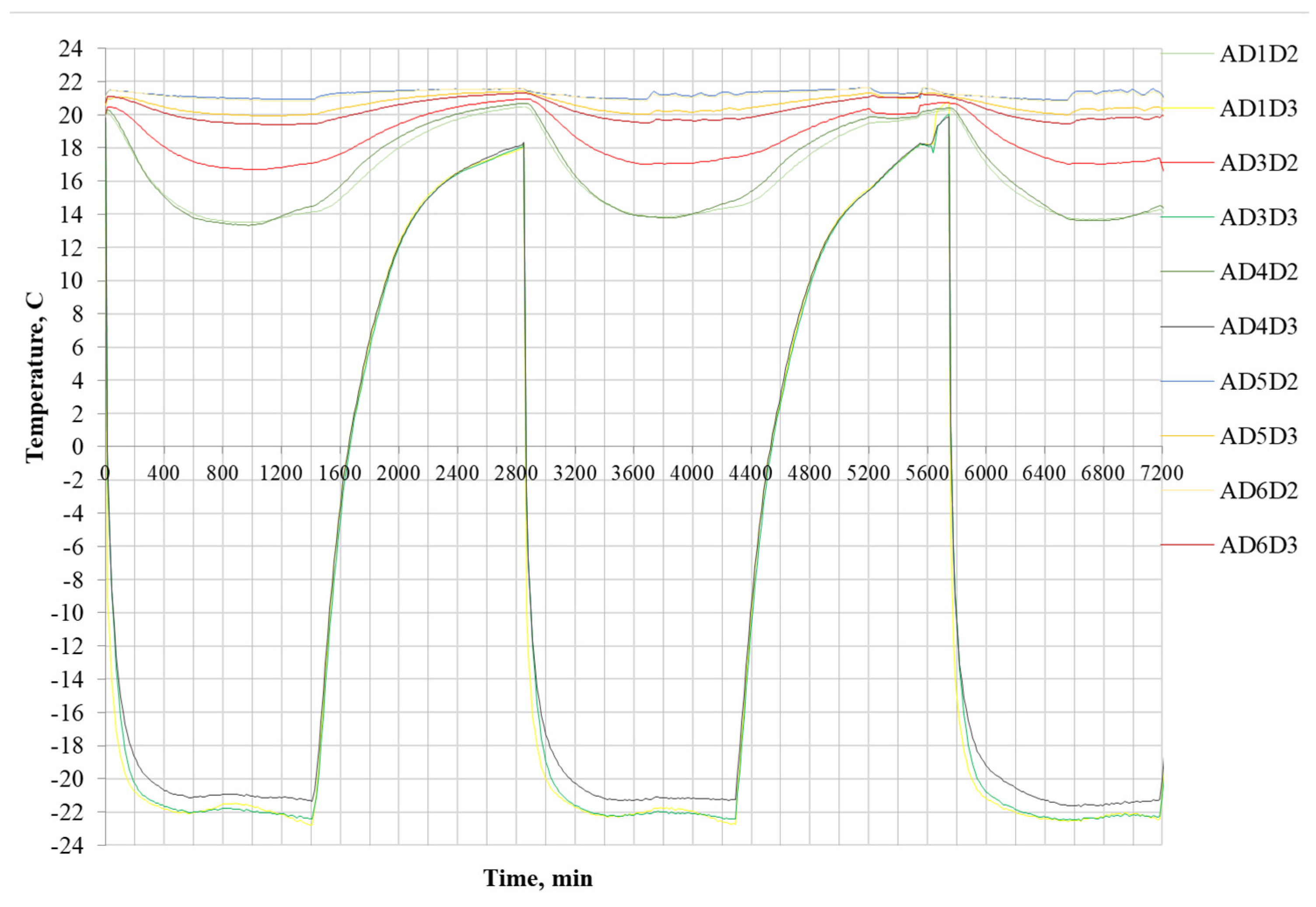
In this work thermal behavior of the structure with different aerogel thickness is analyzed. For the first day the inside temperature sample decreased by 3 °C in the period function both chambers. On the second day the cold chamber had been turned off and the sample gained heat for 24 hours and gradually returned to its original state. On the third day the cold chamber had been turned on and there are sharp drop temperature curves to -22 ° C. For the fourth day the cold chamber had been turned off. On the fifth day it had been turned on again.
The temperature distribution of the structure with aerogel thickness 100 mm is shown at
Figure 15.
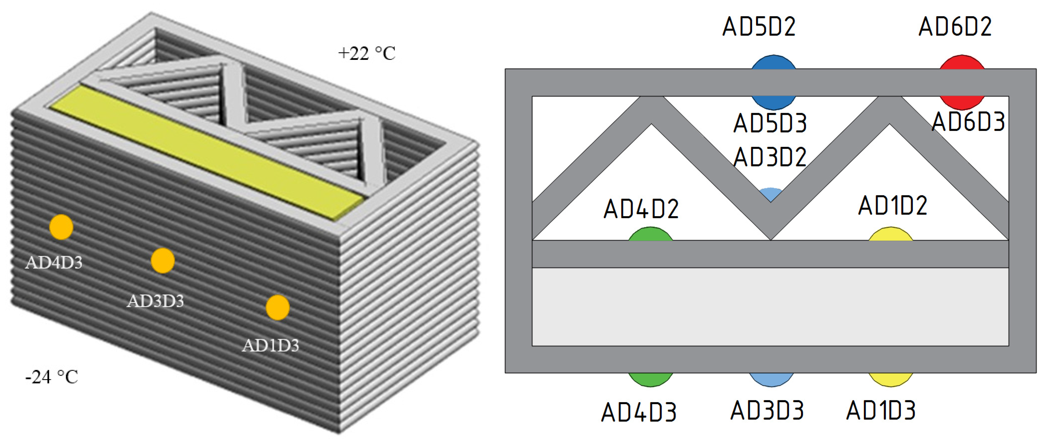
Temperature distribution on the inner surfaces (sensor AD4D2) is shown in
Table 9.
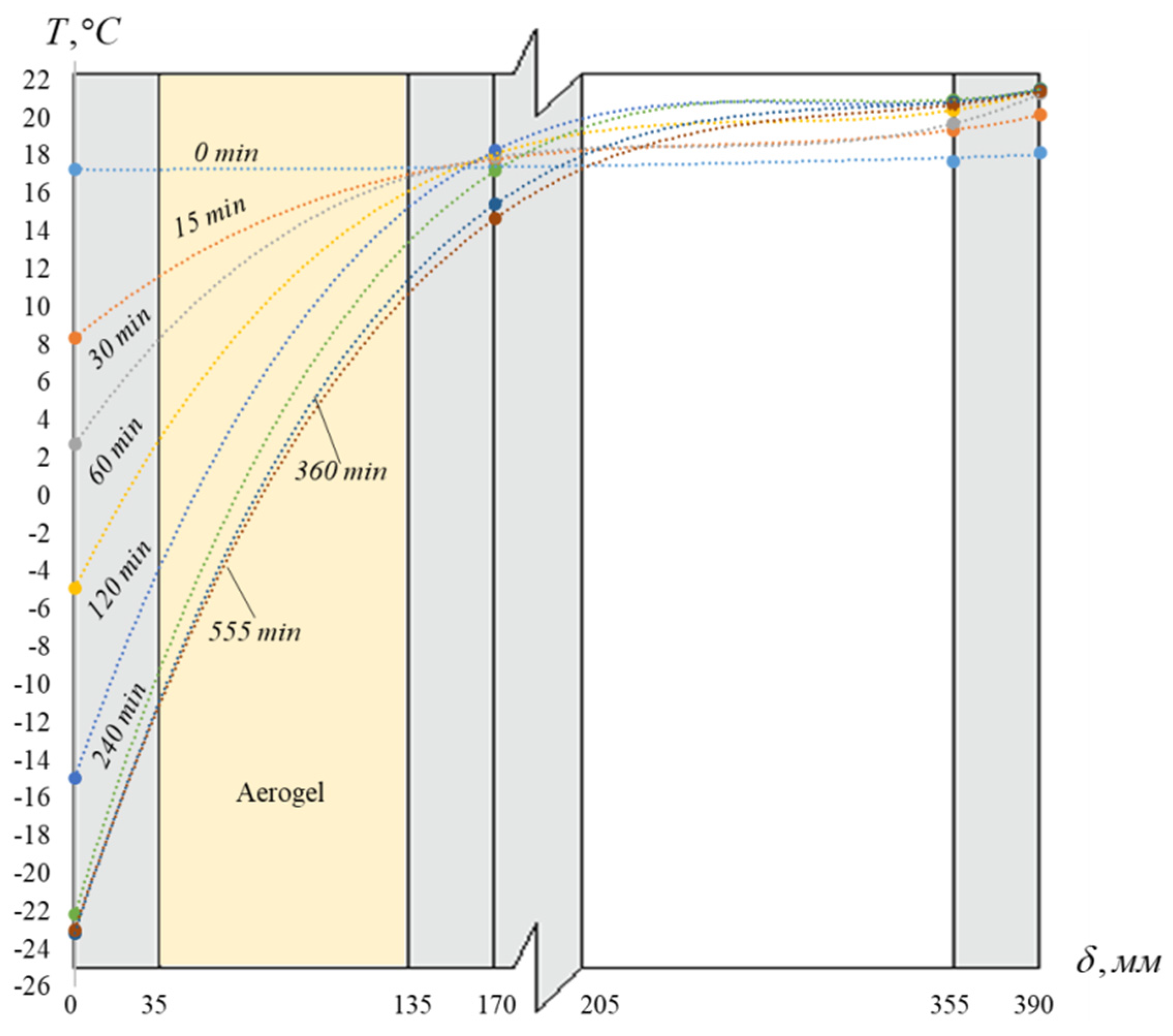
Cooling temperature profile of the additive building structure for the time is shown at
Figure 16.
There is a sharp temperature drop (sensor AD4D2) for 555 minutes and amounted to 2.77 °C by thickness aerogel material 100 mm. After this time 555 minutes there is a slow temperature drop (
Table 10).
The temperature distribution of the structure with aerogel thickness 30 mm is presents at
Figure 17.
Temperature distribution on the inner surfaces (sensor AD4D2) is shown in
Table 11.
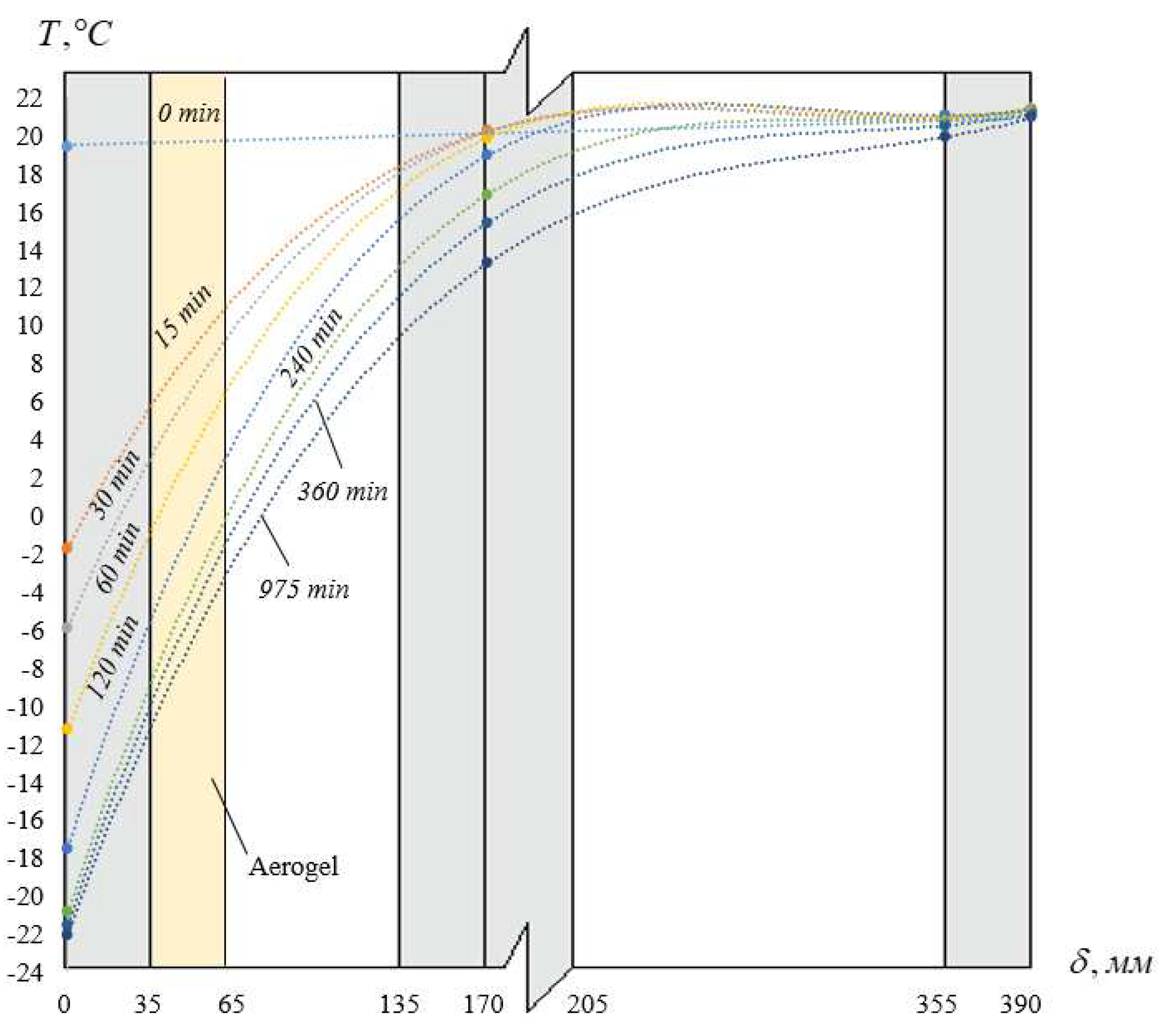
Cooling temperature profile of the additive building structure for the time is shown at
Figure 18.
There is a sharp temperature drop (sensor AD4D2) for 975 minutes and amounted to 6.72 °C by thickness aerogel material 30 mm. After this time 555 minutes there is a slow temperature drop (
Table 12).
3.1.2. Numerical assessment results on thermal performance of aerogel-enhanced building structure
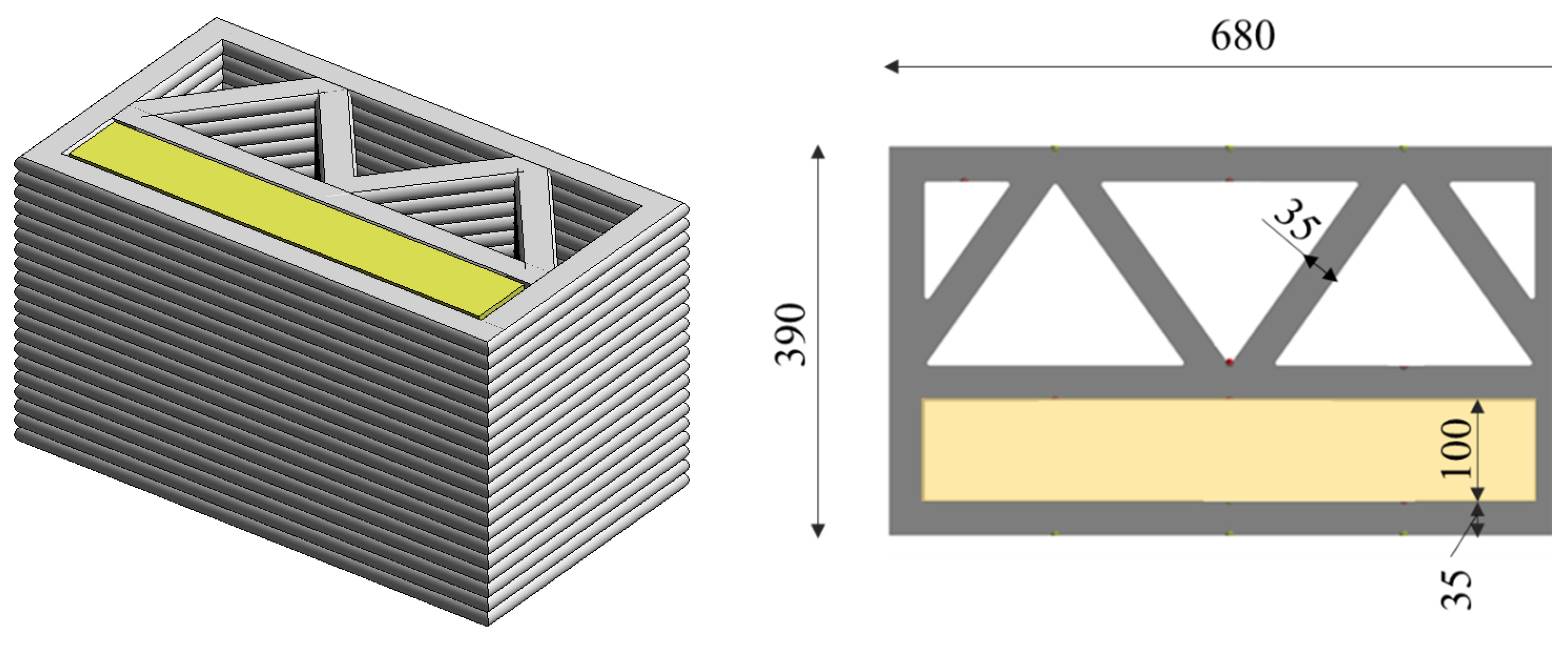
The authors [48] have developed a building envelope with aerogel thermal insulation by additive technologies. The sample has parameters 390x680x310 mm (
Figure 19).
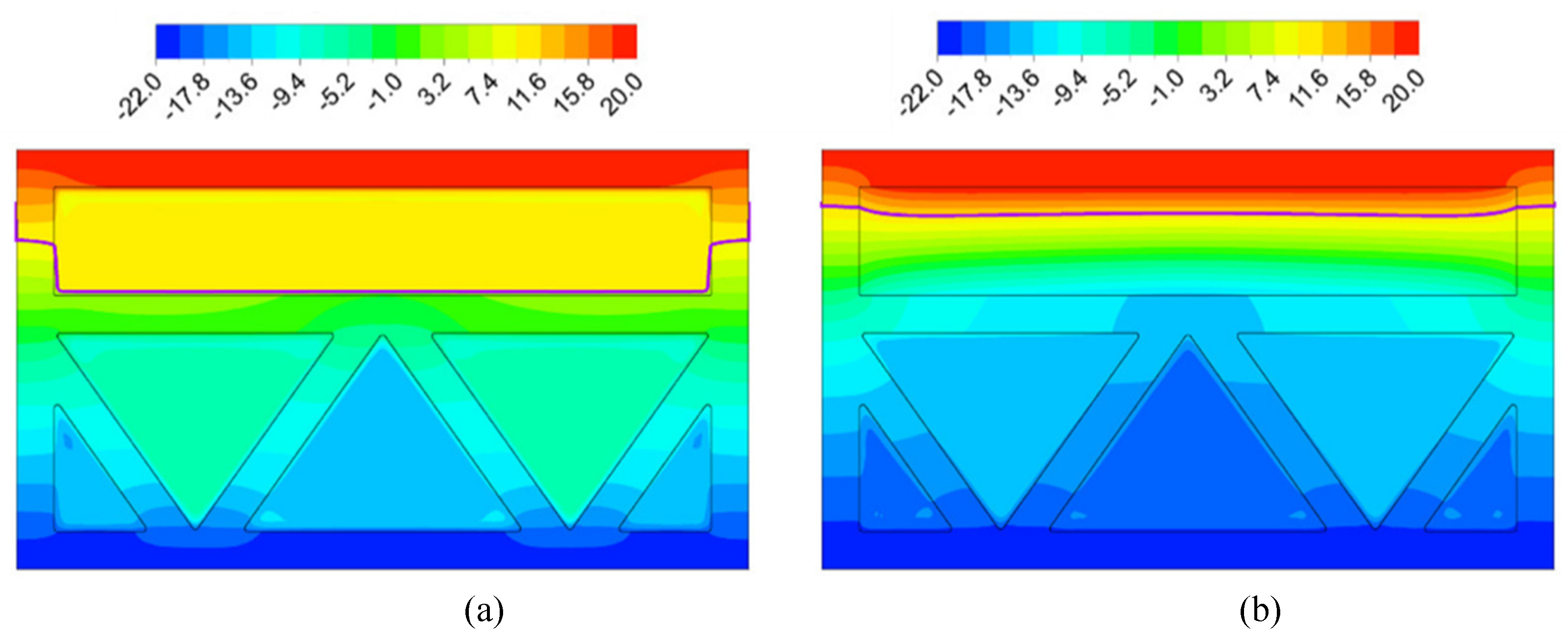
There is economically unprofitable to fill all the sample cavities by aerogel insolation material because of expensive aerogel-based material costs. Based on numerical modeling results of the dew point (
Figure 20) it is efficiency to fill the sample part of the internal room space by the aerogel-based material. The dew point is located inside the insulation, it provides not condense indoors and the dry building structure.
For numerical modeling of the building envelope the calculations had been carried out by bench test conditions. There are three-dimensional model of the enclosing structure and the corresponding calculation grid. The model considers thermal conductivity and convective heat transfer inside air cavities. The boundary conditions are identical (temperature insulation fields at the boundaries of the enclosing structure). The models differ by the material in the “rectangular” cavity: 1) the cavity had been filled by the air, 2) the cavity had been filled by aerogel. The Navier-Stoke’s equations and the heat equation of model are solved by the finite-volume method.
The comparison criterion is the temperature isoline of the dew point at 50% humidity for the internal room temperature. The aerogel application at the building structure increases the heat transmission coefficient. The heat transmission coefficient of the structure without insulation is U = 1.18, for aerogel-enhanced structure heat transmission coefficient is U=0.53.
3.2. Measurement results of thermal performance of the aerogel-enhanced application as mixture powder component of the concrete mixture for printing building
Aerogel powder is usually used as an additive to various mixtures and materials to enhance their thermal insulation properties. For example, aerogel powder can be added to concrete, plasters, and composite materials, providing a high level of thermal insulation without a significant increase in mass. It is also widely used in the research field to create new materials with improved properties.
Experimental assessment of the aerogel application as mixture powder component of the concrete mixture to the insulating concrete properties had been produced in this work paragraph.
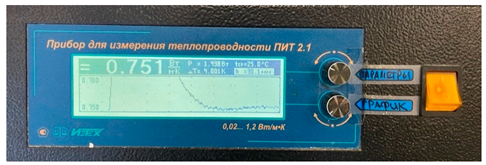
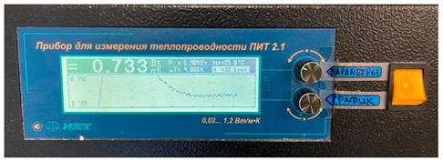
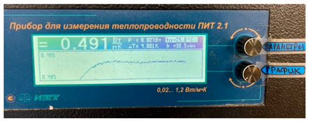
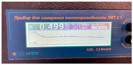
The thermal conductivity measurement results are presented at
Table 13.
The thermal conductivity measurement results of samples without aerogel material presented at
Table 14.
The thermal conductivity measurement results of samples with aerogel material presented at
Table 15.
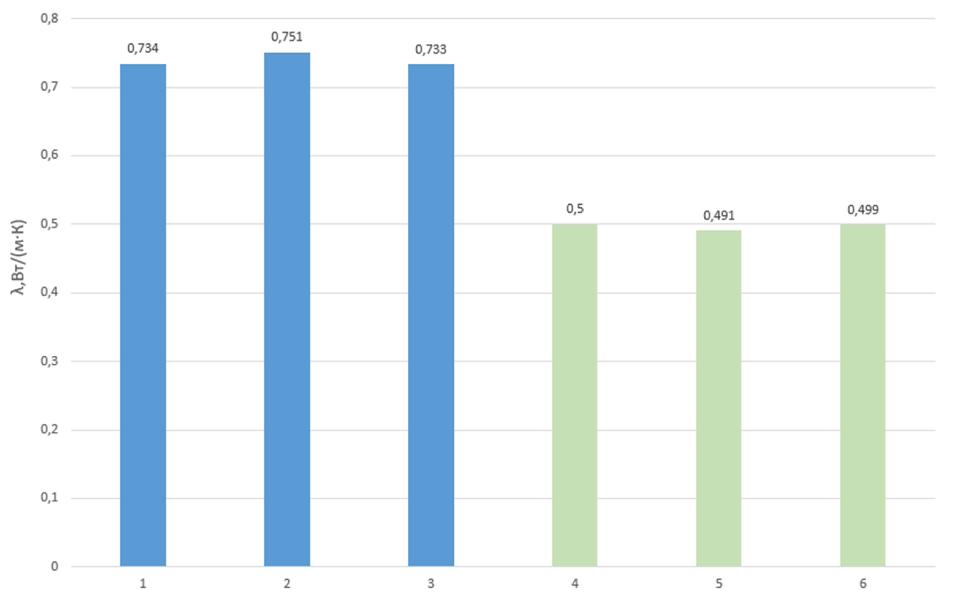
The thermal conductivity measurement results of samples with and without aerogel material presented at
Figure 21.
Experimental and numerical results shown that the aerogel blanket application at the building structure increases the heat transmission coefficient. The heat transmission coefficient of the structure without insulation is U = 1.18, for aerogel-enhanced structure heat transmission coefficient is U=0.53. Experimental results show the effect of aerogel powder component application: thermal conductivity decreased by 25%.
The energy efficiency of additive enclosing walls depends on the configuration of the structure and the thermal insulation materials.
In the studies, the authors reported the similar results [
9,
12,
16]. According to the research results, the use of aerogel blanket allowed to reduce thermal resistance and increase the energy efficiency of building enclosing structures. Based on the measured thermal conductivity and specific heat capacity, thermal conductivity, heat transfer is obtained. The results of the study showed that the thickness can have only a negligible effect on thermal conductivity [
23,
24,
25].
The authors determined that the addition of aerogel powder and aerogel granules can increase the thermal resistance of structures [
19,
20,
21,
22]. The impact of aerogel granule size on the solar light transmittance coefficient was investigated. The study revealed that the use of aerogel granules with a diameter of 1 mm and a layer thickness of 16 mm can reduce heat losses by 22% when facing the horizon and by 10% when facing east or west in hot summer and cold winter conditions [
26].
The advantages of this material over other insulating materials are increasing the thermal resistance of opaque surfaces with an application. Aerogels have the lowest thermal conductivity of any known solid, making them excellent insulators. Despite their strong insulation capabilities, aerogel are lightweight and flexible, making them easy to install and suitable for a wide range of applications [
27]. Some disadvantages include high cost and fragility due to its negligible tensile strength despite its relatively high compressive strength.
Aerogel blankets are porous materials that have high thermal insulation properties. Aerogel blankets are promising materials for application in construction as insulation for walls, ceilings and floors, and ventilation systems. Aerogel blankets are also used for insulation of pipelines at industrial facilities, where, in addition to high thermal insulation, it is also required to resist chemical influences and humidity.
Aerogel powder is usually used as an additive to various mixtures and materials to enhance their thermal insulation properties. For example, aerogel powder can be added to concrete, plasters, and composite materials, providing a high level of thermal insulation without a significant increase in mass. It is also widely used in the research field to create new materials with improved properties.
Aerogel granule is often used in thermal building panels because it can be easily injected between layers to create a lightweight heat insulator. Based on the size of the granules, aerogel can significantly affect the thermal and optical properties of a double-glazed window, building structure etc. The application of the aerogel form (blanket, powder, or granules) depends on the specific requirements of the application and design tasks.
Author Contributions
Conceptualization, D.N. and V.S.; methodology, A.D.; software, E.K.; validation, E.K., V.S. and T.K.; formal analysis, D.A., A.D.; investigation, A.D.; resources, V.S.; data curation, D.N.; writing—original draft preparation, D.A.; writing—review and editing, T.K.; visualization, T.K.; supervision, V.S. and D.N.; project administration, D.N.; funding acquisition, D.N. All authors have read and agreed to the published version of the manuscript.
Figure 1.
The types of aerogel application.
Figure 1.
The types of aerogel application.
Figure 2.
The aerogel-enhanced blanket.
Figure 2.
The aerogel-enhanced blanket.
Figure 3.
The aerogel granule and aerogel powder.
Figure 3.
The aerogel granule and aerogel powder.
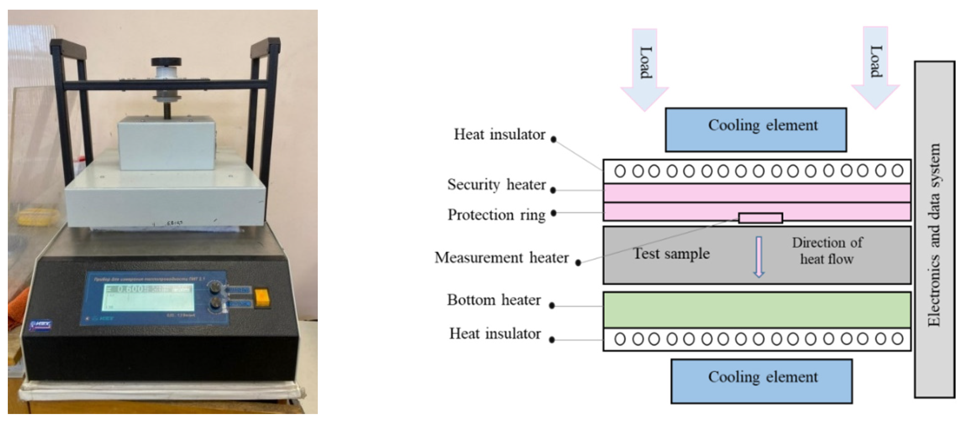
Figure 4.
Heat flow meter PIT-2.1 (a) and its schematic design (b).
Figure 4.
Heat flow meter PIT-2.1 (a) and its schematic design (b).
Figure 5.
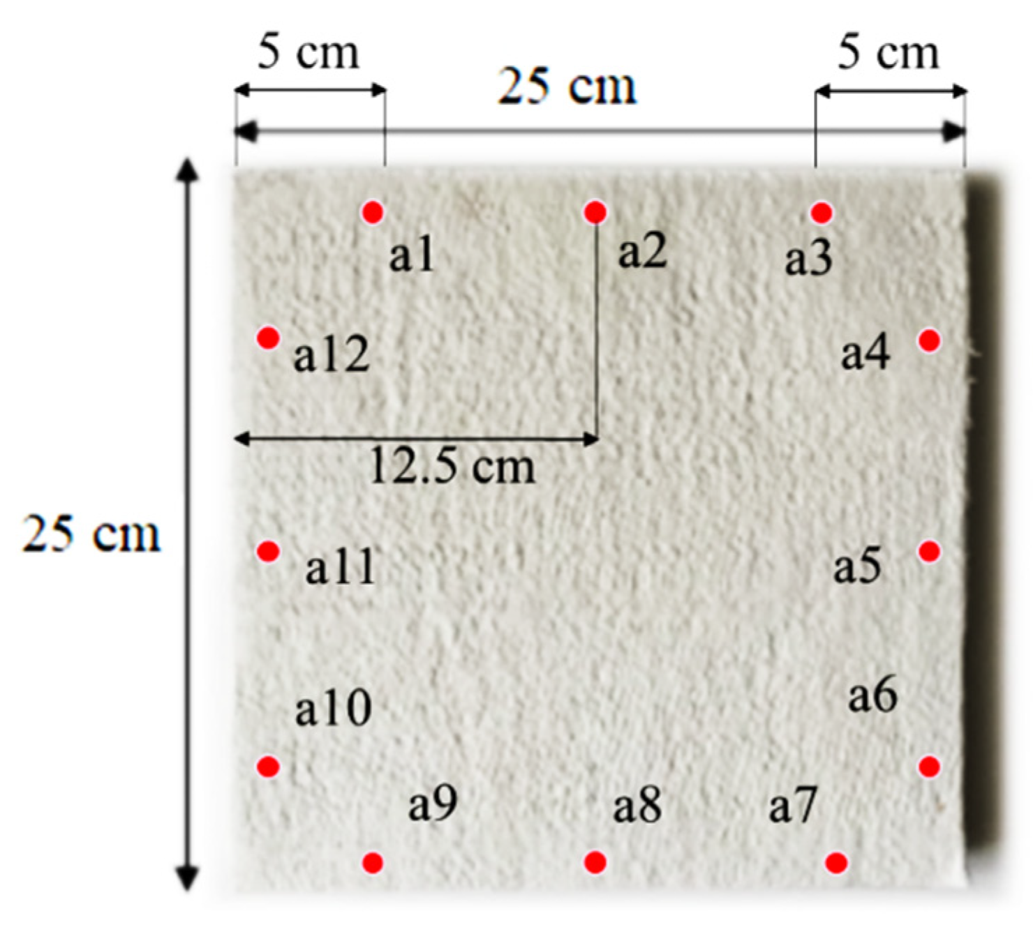
The aerogel sample scheme of the thickness measuring points.
Figure 5.
The aerogel sample scheme of the thickness measuring points.
Figure 6.
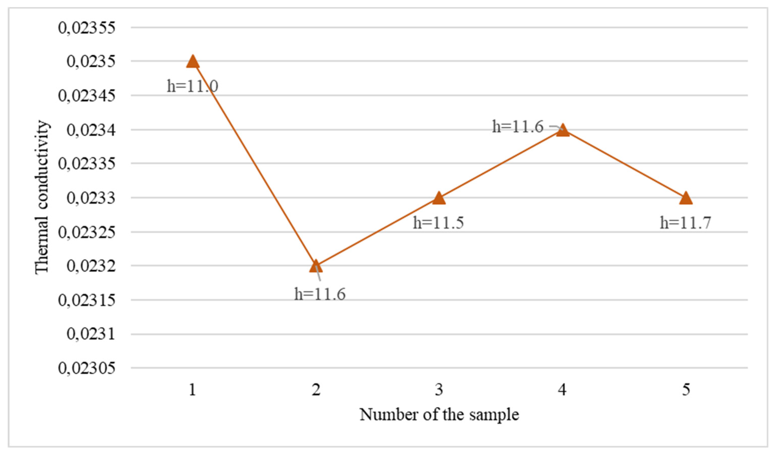
Thermal conductivity of the aerogel-blanket samples.
Figure 6.
Thermal conductivity of the aerogel-blanket samples.
Figure 7.
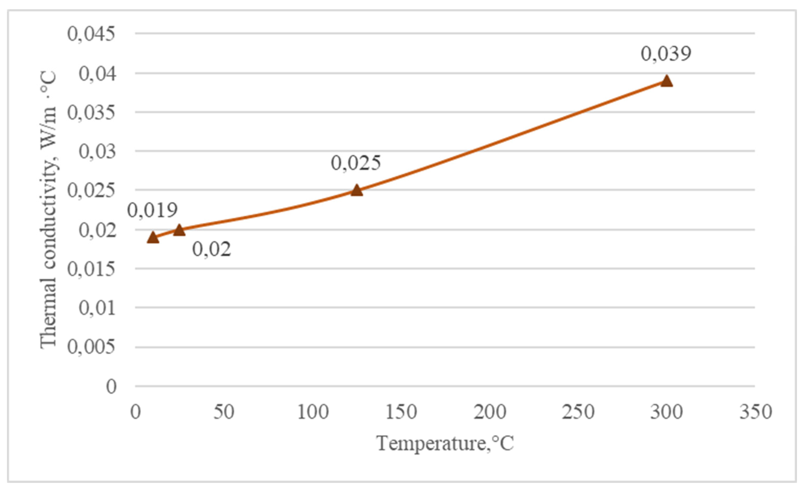
The thermal conductivity dependence from temperature for Alison Aerogel Blanket DRT06 series3.
Figure 7.
The thermal conductivity dependence from temperature for Alison Aerogel Blanket DRT06 series3.
Figure 8.
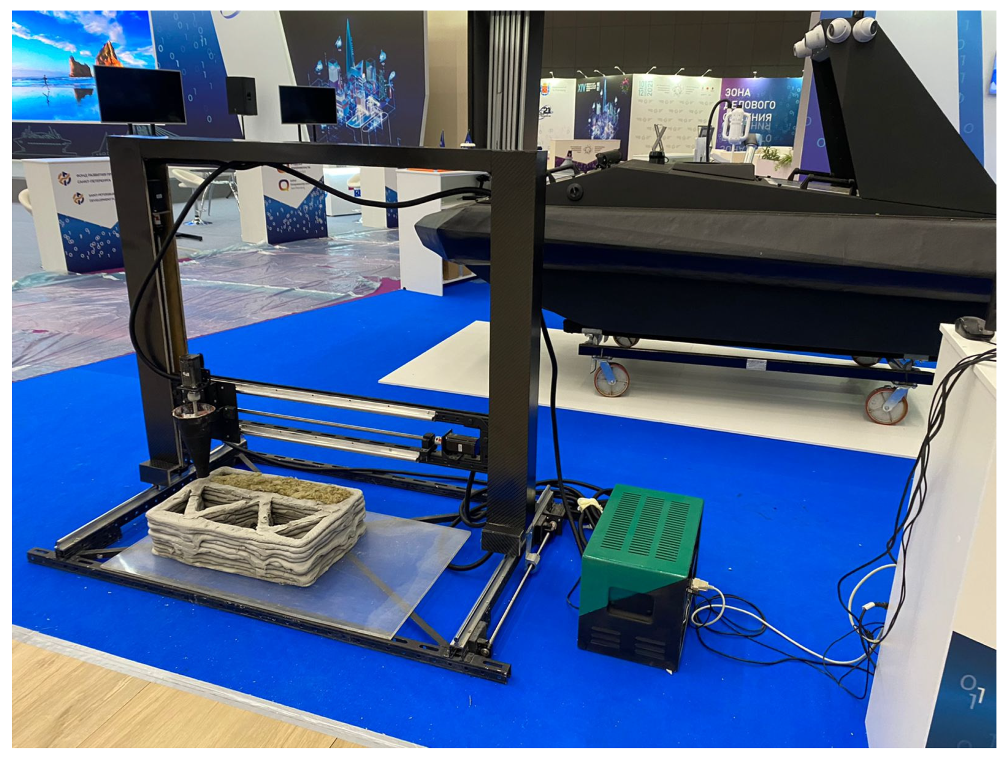
Aerogel-enhanced building envelope by 3D printer.
Figure 8.
Aerogel-enhanced building envelope by 3D printer.
Figure 9.
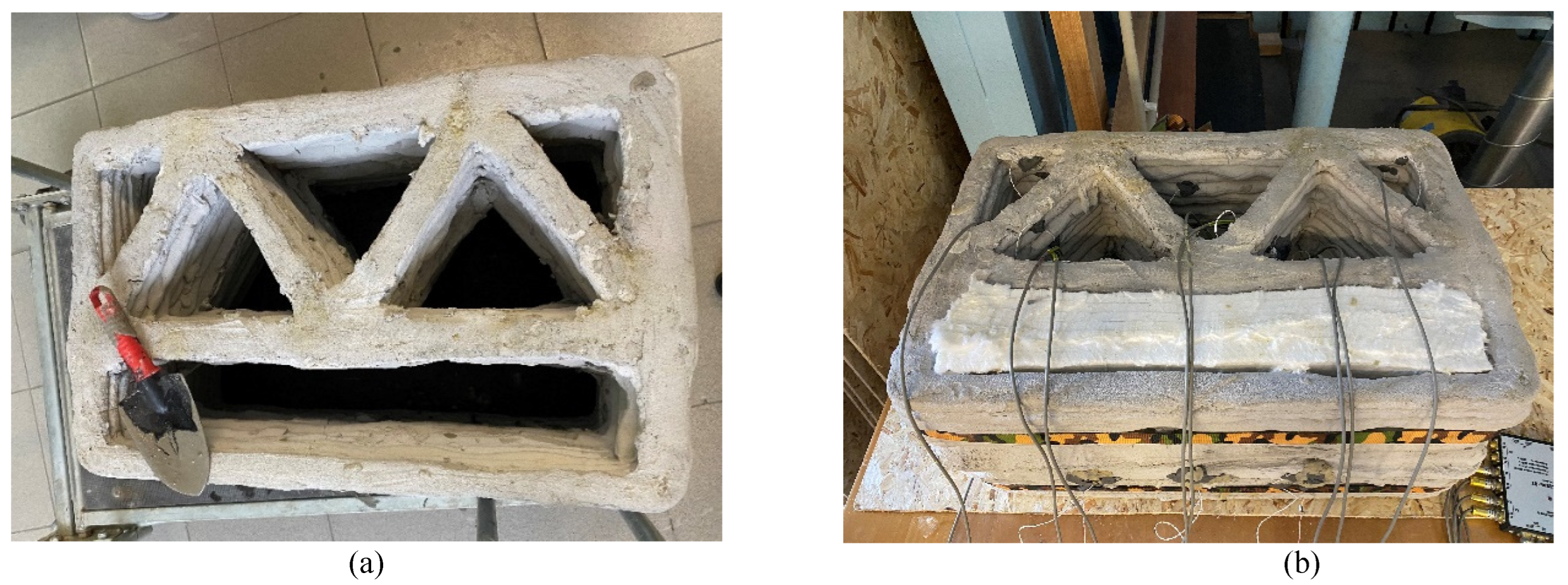
Additive building structure a) no insulation b) with aerogel-blanket insulation material.
Figure 9.
Additive building structure a) no insulation b) with aerogel-blanket insulation material.
Figure 10.
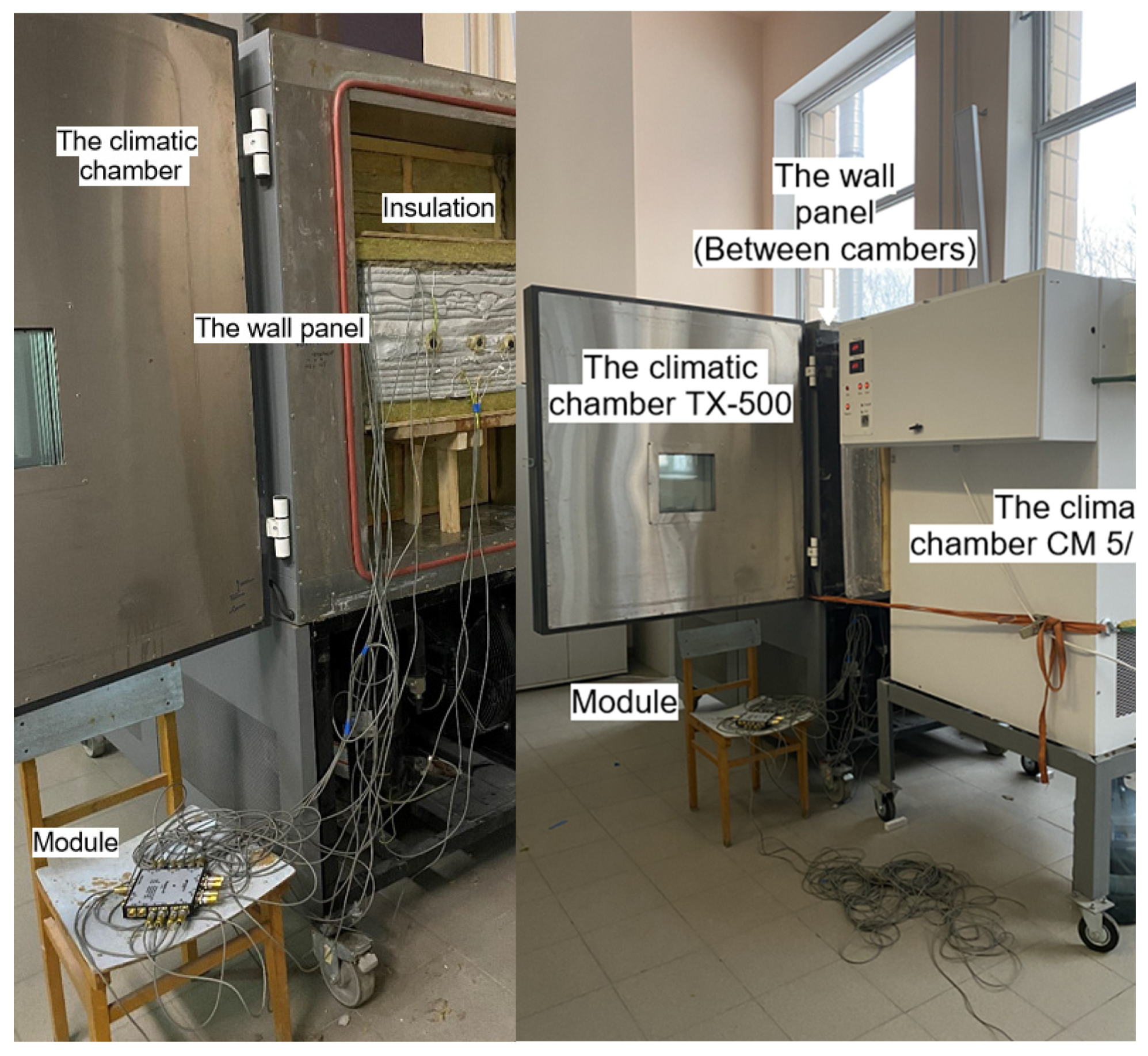
Experimental setup of Additive building structure.
Figure 10.
Experimental setup of Additive building structure.
Figure 11.
The aerogel-enhanced building structure sample by additive technologies. The temperature sensor’s points location.
Figure 11.
The aerogel-enhanced building structure sample by additive technologies. The temperature sensor’s points location.
Figure 12.
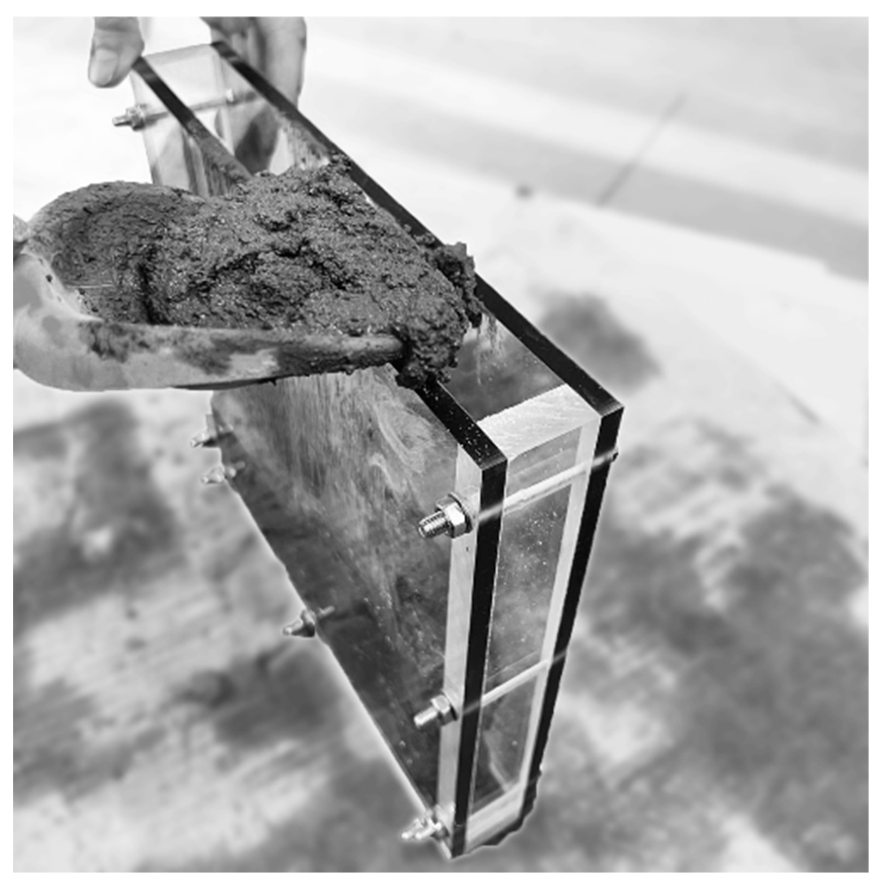
The concreting sample processes.
Figure 12.
The concreting sample processes.
Figure 13.
Aerogel a) at the granules state b) at the powder state.
Figure 13.
Aerogel a) at the granules state b) at the powder state.
Figure 14.
The samples thicknesses scheme.
Figure 14.
The samples thicknesses scheme.
Figure 15.
Temperature distribution inside the structure for 7200 minutes.
Figure 15.
Temperature distribution inside the structure for 7200 minutes.
Figure 16.
Cooling temperature profile of the additive building structure for the time.
Figure 16.
Cooling temperature profile of the additive building structure for the time.
Figure 17.
Temperature distribution inside the structure for 7200 minutes.
Figure 17.
Temperature distribution inside the structure for 7200 minutes.
Figure 18.
Cooling temperature profile of the additive building structure for the time.
Figure 18.
Cooling temperature profile of the additive building structure for the time.
Figure 19.
Aerogel Insulated Additive Manufacturing Structure.
Figure 19.
Aerogel Insulated Additive Manufacturing Structure.
Figure 20.
Temperature distribution for additive design a) without aerogel b) with aerogel.
Figure 20.
Temperature distribution for additive design a) without aerogel b) with aerogel.
Figure 21.
The thermal conductivity of the samples with and without aerogel.
Figure 21.
The thermal conductivity of the samples with and without aerogel.
Table 1.
The estimation results of aerogel-blanket sample thickness.
Table 1.
The estimation results of aerogel-blanket sample thickness.
№
sampl. |
а1 |
a2 |
a3 |
a4 |
a5 |
a6 |
a7 |
a8 |
a9 |
a10 |
a11 |
a12 |
Avg.
value |
| 1 |
11.3 |
11.1 |
10.8 |
11.2 |
11.2 |
11.0 |
10.8 |
10.9 |
11.1 |
10.6 |
11.2 |
10.9 |
11.0 |
| 2 |
11.4 |
11.5 |
11.8 |
11.6 |
11.8 |
11.8 |
11.6 |
11.3 |
11.8 |
11.8 |
11.7 |
11.1 |
11.6 |
| 3 |
11.5 |
11.4 |
11.4 |
11.4 |
11.6 |
11.5 |
11.4 |
11.3 |
11.5 |
11.5 |
11.6 |
11.4 |
11.5 |
| 4 |
11.5 |
11.5 |
11.4 |
11.4 |
11.7 |
11.5 |
11.6 |
11.3 |
11.6 |
11.7 |
11.7 |
11.7 |
11.6 |
| 5 |
11.6 |
11.6 |
11.4 |
11.5 |
11.7 |
11.5 |
11.7 |
11.5 |
11.6 |
11.7 |
11.7 |
11.7 |
11.7 |
Table 2.
Measurement of thermal conductivity of an aerogel-based material.
Table 2.
Measurement of thermal conductivity of an aerogel-based material.
Average temperature
of the sample, °С |
Thermal conductivity,
λ, W/m·°С |
| 10 |
0.019 |
| 25 |
0.020 |
| 125 |
0.025 |
| 300 |
0.039 |
Table 3.
The mixture parameters of concrete samples without aerogel.
Table 3.
The mixture parameters of concrete samples without aerogel.
| Dry mix, kg |
Water, l |
Volume, l |
Comment |
|
19.50.14 = 2.73
|
10 |
Manufacturer data |
| 1.95 |
0.273 |
1 |
Specific |
| 3.66 |
0.512 |
1.875 |
1 form |
| 7.32 |
1.024 |
3.75 |
2 forms |
Table 4.
The mixture parameters of concrete samples with aerogel 15%.
Table 4.
The mixture parameters of concrete samples with aerogel 15%.
| Dry mix, kg |
Water, l |
Aerogel, l |
Volume, l |
Comment |
| 1.66 |
0.232 |
0.15 |
1.0 |
Specific |
| 3.11 |
0.435 |
0.281 |
1.875 |
1 form |
| 6.22 |
0.870 |
0.562 |
3.75 |
2 forms |
| 6.842 |
0.957 |
0.618 |
4.125 |
2 forms + 10% assurances |
| 6.842 |
1.057 |
0.618 |
4.225 |
+ 100 ml of water |
Table 5.
The thermal conductivity coefficient of concrete samples.
Table 5.
The thermal conductivity coefficient of concrete samples.
| No |
Sample type |
Sample thickness, mm |
The thermal conductivity coefficient
|
| 1 |
with aerogel |
30.1 |
0.917 |
| 2 |
with aerogel |
29.8 |
1.11 |
| 3 |
without aerogel |
30.2 |
1.5 |
| 4 |
without aerogel |
30.1 |
1.22 |
Table 6.
Thickness of concrete samples.
Table 6.
Thickness of concrete samples.
| No |
|
|
|
|
|
|
|
|
|
t |
| 1 |
30.3 |
29.75 |
29.9 |
29.7 |
30.3 |
30.3 |
30.2 |
30.2 |
30.1 |
36.8 |
| 2 |
29.05 |
28.8 |
30.0 |
30.0 |
30.1 |
30.1 |
30.25 |
30.1 |
29.8 |
36.5 |
| 3 |
30.0 |
30.5 |
29.65 |
30.05 |
30.0 |
30.85 |
30.6 |
30.2 |
30.2 |
36.9 |
| 4 |
29.65 |
30.65 |
30.2 |
30.2 |
30.05 |
30.1 |
30.0 |
30.1 |
30.1 |
36.8 |
Table 7.
Powder component’s proportion.
Table 7.
Powder component’s proportion.
| No |
Component |
Unit |
Value |
15% |
| 1 |
Dry plaster mixture by gypsum binder |
kg/l |
2.25/3.1 |
1.91/2.635 |
| 2 |
Aerogel (Alison Aerogel Blanket) |
l |
- |
0.5/0.465 |
| 3 |
Water |
kg/l |
1.46/1.46 |
1.46/1.46 |
| |
Water-binding ratio |
- |
0.65 |
Table 8.
The samples thicknesses measurement.
Table 8.
The samples thicknesses measurement.
| No |
h1, mm |
h2, mm |
h3,mm |
h4,mm |
h5,mm |
h6,mm |
h7,mm |
h8,mm |
havrg,mm |
| 1 |
30.1 |
30.2 |
30.3 |
30.2 |
29.8 |
30.3 |
29.9 |
30.1 |
30.1 |
| 2 |
30.1 |
30.2 |
30.3 |
30.2 |
29.8 |
30.3 |
29.9 |
30.1 |
30.1 |
| 3 |
30.1 |
30.2 |
30.3 |
30.2 |
29.8 |
30.3 |
29.9 |
30.1 |
30.1 |
| 4 |
30.4 |
30.5 |
30.3 |
30.6 |
30.4 |
30.4 |
30.7 |
30.6 |
30.5 |
| 5 |
30.4 |
30.5 |
30.3 |
30.6 |
30.4 |
30.4 |
30.7 |
30.6 |
30.5 |
| 6 |
30.4 |
30.5 |
30.3 |
30.6 |
30.4 |
30.4 |
30.7 |
30.6 |
30.5 |
Table 9.
Temperature distribution on the inner surfaces (sensor AD4D2).
Table 9.
Temperature distribution on the inner surfaces (sensor AD4D2).
| |
1 day |
2 days |
3 days |
4 days |
5 days |
| Temperature reduction |
-3.5 °С |
|
-6°С |
|
-5°С |
| Temperature increase |
|
+5°С |
|
+5°С |
|
Table 10.
Temperature distribution of building structure sample for the first 555 minutes.
Table 10.
Temperature distribution of building structure sample for the first 555 minutes.
| Time, min |
AD3D3 |
AD4D2 |
AD5D3 |
AD5D2 |
| 0 |
17.27 |
17.47 |
17.73 |
18.19 |
| 15 |
8.35 |
17.83 |
19.37 |
20.16 |
| 30 |
2.74 |
17.93 |
19.71 |
21.28 |
| 60 |
-4.89 |
18.11 |
20.42 |
21.47 |
| 120 |
-14.92 |
18.28 |
20.85 |
21.54 |
| 240 |
-22.15 |
17.21 |
20.97 |
21.55 |
| 360 |
-23.16 |
15.45 |
20.86 |
21.48 |
| 555 |
-22.96 |
14.7 |
20.7 |
21.41 |
| Coordinate, mm |
0 |
170 |
355 |
390 |
Table 11.
Temperature distribution on the inner surfaces (sensor AD4D2).
Table 11.
Temperature distribution on the inner surfaces (sensor AD4D2).
| |
1 day |
2 day |
3 day |
4 day |
5 day |
| Temperature reduction |
-6.5 °С |
|
-7°С |
|
-6.7°С |
| Temperature rise |
|
+7.5°С |
|
+5.5°С |
|
Table 12.
Temperature distribution of building structure sample for the first 975 minutes.
Table 12.
Temperature distribution of building structure sample for the first 975 minutes.
| Time, min |
AD3D3 |
AD4D2 |
AD5D3 |
AD5D2 |
| 0 |
19.55 |
20.05 |
20.54 |
21.15 |
| 15 |
-1.65 |
20.29 |
20.98 |
21.38 |
| 30 |
-5.8 |
20.24 |
20.91 |
21.51 |
| 60 |
-11.23 |
19.91 |
21.02 |
21.47 |
| 120 |
-17.38 |
19.01 |
21.06 |
21.41 |
| 240 |
-20.84 |
16.95 |
20.85 |
21.3 |
| 360 |
-21.48 |
15.47 |
20.55 |
21.19 |
| 975 |
-21.97 |
13.33 |
19.96 |
20.96 |
| Coordinate, mm |
0 |
170 |
355 |
390 |
Table 13.
The thermal conductivity coefficient of concrete samples.
Table 13.
The thermal conductivity coefficient of concrete samples.
| No |
Sample type |
Sample thickness, mm |
The thermal conductivity coefficient
|
| 1 |
with aerogel |
30.1 |
0.917 |
| 2 |
with aerogel |
29.8 |
1.11 |
| 3 |
without aerogel |
30.2 |
1.5 |
| 4 |
without aerogel |
30.1 |
1.22 |
Table 14.
The thermal conductivity measurement of samples without aerogel material.
Table 15.
The thermal conductivity measurement of samples with aerogel material.
