1. Introduction
The inevitable combustion of fossil fuels releases massive amounts of greenhouse gases (GHGs), especially CO
2, which is the leading cause of global warming and climate change [
1]. CO
2 alone contributes 20 % of the emitted GHGs that increased by more than 15 % in the last decade to reach nearly 30 billion tons with a high expectation to be doubled by 2050 [
2,
3]. Thereby, it is crucial to reduce 20 gigatons/year of the emitted CO
2 within the coming thirty years and to near zero at the end of this century to decrease the Earth’s temperature to 6
°C [
4]. CO
2 mitigation in the atmosphere is investigated via two strategies : capture and utilization. CO
2 could be captured by numerous high surface porous materials [
5], or converted into useful compounds such as dimethyl carbonate [
6], or via dry reforming [
7], CO
2 hydrogenation to methanol [
8], and CO
2 methanation [
9]. Dry reforming reactions require high operating temperatures, as CH
4 and CO
2 are thermally stable compounds in addition to the fast coke formation, as carbon originates from two sources (CH
4 and CO
2), which poisons the catalyst and blocks the reactors [
10]. In addition, the track of CO
2 hydrogenation to methanol requires severe operating conditions, such as high reaction temperatures and high applied pressures, which means high operatinal cost [
8].
Hydrogenation of CO
2 to methane (eq. (1)) or to methanol (eq. (2)) are possible pathways to the utilization of CO
2, but thermodynamically speaking, more heat is released by the CO
2 methanation[
11].
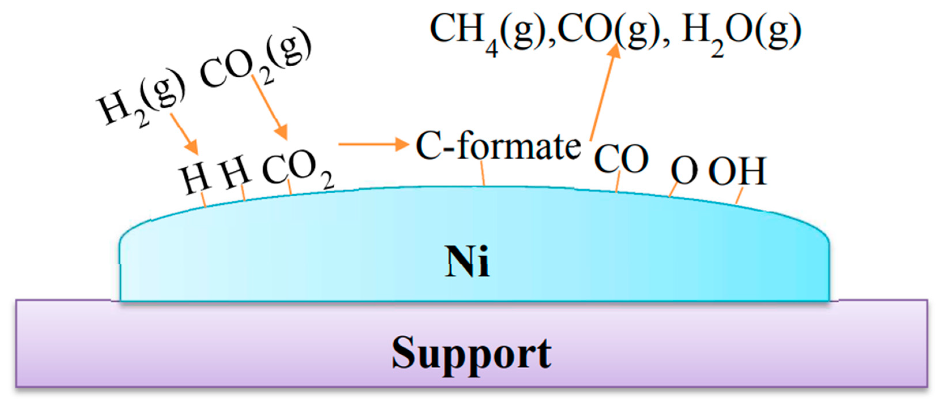
A simplified mechanism of CO2 methanation is displayed in
Scheme 1; example is given for supported nickel nanocatalyst. However, it is to note that the mechanisms could be affected by the support nature[
12].
Thus, among the CO
2 applications, the methanation reaction is simple to be conducted, under mild temperature conditions (in the 200-500 °C range), and more importantly, such a reaction could be done at ambient pressure [
13]. These salient features of CO
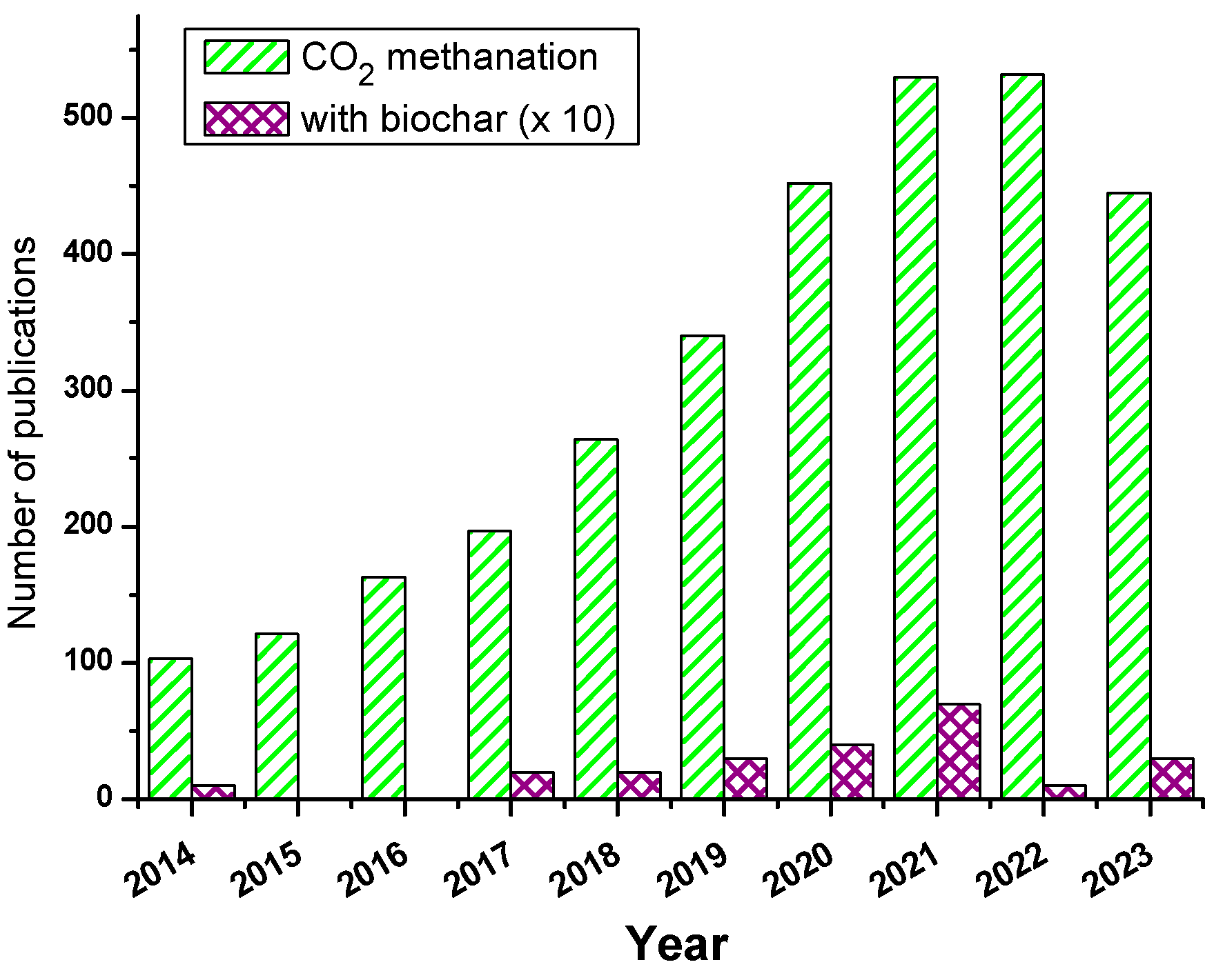
2 methanation made it highly popular as witnessed from
Figure 1, showing the remarkable increase in publications on CO
2 methanation in the last ten years. Yet, CO
2 methanation requires efficient catalysts, and in this regard, mono, bimetallic nanocatalysts, and other metal/metal oxide combined catalysts were employed in the pure form or in the dispersed state. In the latter case, high surface area catalyst supports are required, and numerous have been employed, namely silica, zeolite, clay, MOF, and carbon allotropes. However, the emerging high-performance material coined as « biochar » has just started to be investigated as nanocatalyst support for CO
2 methanation.
Given the sky-rocketing number of publications on biochar (about 5-6000 publications yearly since 2021), it is clear that this support obtained by thermochemical treatment of the biomass, mostly lignocellulosic trash, has much to offer, and this is what has attracted us. In the past two years, we have spent time and effort on the design of biochar@nanocatalyst from various lignocellulosic wastes for the degradation of dyes [
14,
15,
16,
17] and the elimination of other emerging pollutants. Apart from de-pollution, and investigating green and valuable methods to design biochar-based materials for the energy sector, we have decided to invest time on the attractive and challenging process of CO
2 methanation. It is also important to draw the attention of materials scientists and catalysis experts on the growing role of biochar in this area. Although there is abundant literature on the design of catalysts for CO
2 methanation, our search using the Web of Science returned no specific review, focussing on biochar-immobilized nanocatalysts for CO
2 methanation; hence the motivation for this contribution.
2. Biochar@catalyst fabrication and modification
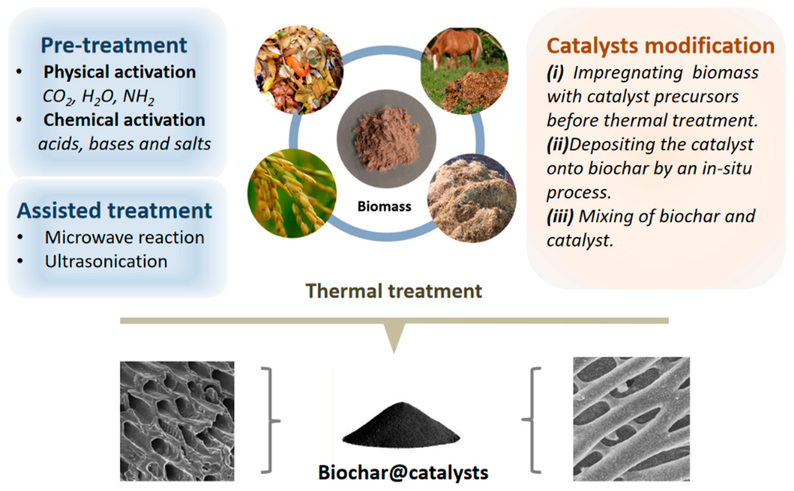
Biochar serves as an ideal porous support for catalysts, prepared by thermochemical methods. Through the various pretreatments or loading of metal nanoparticles to tune its physicochemical properties, the fabrication process results in promising biochar-based composite materials. We present a comprehensive overview of biochar modification, focusing primarily on physical modification, chemical modification, nanoparticle modification and sequence of wetness impregnation/pyrolysis (
Figure 2).
2.1. Fabrication process
Thermochemical methods have emerged as a promising technology for the conversion of biomass into valuable products[
18]. Herein, the focus is on biomass pyrolysis-derived biochar immobilized metal catalysts, presenting the carbonaceous materials as a popular topic for environmentally friendly alternatives.
Pyrolysis is a common thermochemical technology, biomass Biomass undergoes carbonization in an inert or oxygen-limited conditions, and heated above its thermal stability limit without combustion [
19,
20], resulting in more stable products and solid residues, including large quantities of liquids (bio-oil), solids (biochar) and gases (biosyngas) [
21]. Both in fast pyrolysis and flash pyrolysis, biomass is rapidly heated to high temperatures within a short residence time, resulting in dominant yields of oil and gas over charcoal [
22,
23]. In contrast, slow pyrolysis, characterized by med-high temperatures (500-900 ℃), a slow heating rate (5-10 K/min), and an extended residence time (≥10 min), provides an ideal environment and sufficient duration to the production of solid carbonaceous materials, particularly biochar-based materials.
2.2. Precursor material pretreatment
Common functional groups attaching the surface of biochar are determined by the raw materials and the pyrolysis conditions. The pretreatment of the biomass, biochar precursor, is a viable strategy to tailor the surface properties of composite catalysts. This section will primarily discuss the impact of physical and chemical pretreatments.
2.2.1. Physical pretreatment
Physical pretreatment is a pivotal step in enhancing catalyst activity. Most physical activation is performed on the obtained biochar during high-temperature carbonization in an atmosphere of CO
2, H
2O
2, NH
2 or water vapor. Sun et al. [
24] proposed a method for the preparation of biochar-based catalysts through the CO
2 activation for impedance reduction. They first heated the biochar to a set temperature under N
2 atmosphere (800-900 ℃), then CO
2 (500 mL/min) was injected to start the activation for 1 h. The obtained biochar enhanced the graphitization to improve the electron transfer ability.
Iberahim et al.[
25] prepared oil palm fiber activated biochar at 753 °C for 73 min of activation time with 497 ml/min of CO
2 flow. The pH value of activated biochar was higher than pure biochar and increased as the activation temperature increased from 600 to 800 °C. The catalyst surface pH provides valuable insights into the adsorption of gas molecules, combining consideration into the acidity and basicity of target gas molecules. As the biochar is activated under a CO
2 atmosphere at high temperatures, involves oxidative treatment, effectively improving structural characteristics that enhance its suitability for applications in catalysis[
19].
Feng et al.[
26] in their work described H
2O activated biochar and ammonia activated biochar. They used corn straw as raw materials, and activated biochar were prepared by NH
3·H
2O activation and H
2O activation to design the biochars with hierarchical pore and O/N functional groups, the N-containing functional groups on ammonia activated biochar surface have greater adsorption energy for CO
2 and NH
3 adsorption than O-containing groups of H
2O activated biochar. This result also highlights the significance of chemical functionalities on the catalyst surface in enhancing performance.
2.2.2. Chemical pretreatment
Chemical pretreatment is another critical precursor material activated method, involving activators include acids, bases, salts, and more. Based on literature reports, employing chemical activation methods for precursor treatment has been shown to develop the catalyst properties, such as surface area, porosity, functional groups, and active sites in order to increase biochar reaction rate.
Tang et al. [
27] used pine nut shells to obtain biochar through KOH pretreatment and calcination method. Its microporosity was 20 times higher than that of biochar without KOH pretreatment, and its specific surface area was as high as 1850 m
2·g
−1, which is very suitable for CO
2 adsorption (CO
2 uptake of 6.05 mmol·g
−1 at 1 bar, 273 K).
African almond leaves were firstly treated with phosphoric acid (H
3PO
4), followed by pyrolysis at high temperatures in an inert environment. Embedding phosphoric acid functional groups (PO
43-) on the surface through chemical pretreatment increases the adsorption capacity of biochar and can remove >98% of MB dye molecules within 30 minutes [
28]. Nguyen et al.[
29] researched the pore-forming effect of ZnCl
2 decomposition during thermal treatment to improve the physicochemical properties of biochar is good strategies. Biochar derived from brown algal
Ascophyllum nodosum was synthesized through hydrothermal carbonization (HTC) coupling with ZnCl
2 chemical activation at 700 °C. The activating process with ZnCl
2 changed the pyrolysis path of biochar and improved accessible binding sites as proved by TG and BET analyses, its acidic and basic groups on the biochar surface have also been modified.
2.3. Nanoparticle loading
Metal loading is a crucial factor influencing the performance of composite catalysts. Biochar materials can be functionalized or modified with the addition of nanoparticles during thermal treatment or physical-chemical reactions, which the generated composites combine the properties of biochar and nanoparticles. This section will primarily intended to discuss the impact of different metal loading methods, such as wet impregnation, in-situ process and more. Relevant literature will be summarized to illustrate the effects of various metal loading strategies on the catalytic activity of composite catalysts.
Snoussi et al. [
30] pretreated the biomass by maceration in hydroalcoholic mixture with ultrasonication-assistance then impregnated with copper and silver nitrate salts prior to pyrolysis at 500 °C under N
2:H
2 95 %:5% for 1 h, therefore leading to biochar-supported Ag/Cu nanoparticles. Compared to pristine biochar, the biochar made out of the macerated biomass exhibited a noticeable microporosity, with more accessible porous structure. N
2-physisorption measurements proved the specific surface area of Ag/Cu-Biochar increased by 20 % and its pore volume has a 25-fold increase.
Prabhakaran et al. [
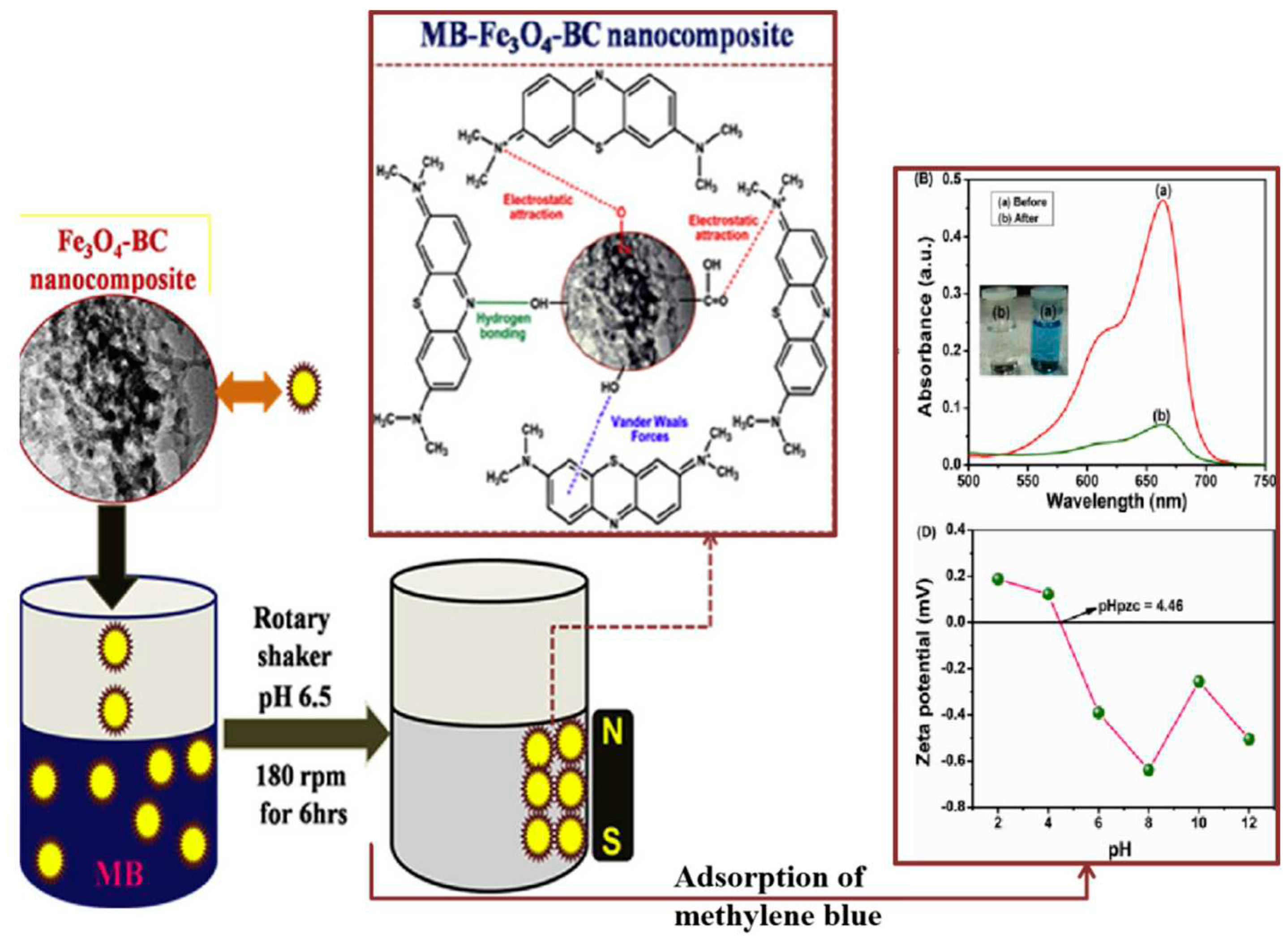
31] proposed to modify the surface of biochar by introducing iron oxide nanoparticles, and elaborated on the synthesis process of wetness impregnation for 1 h and hydrothermal method at 180 °C for 12 h to prepare magnetic biochar nanocomposites (
Figure 3). The biochar-based iron oxide nanocomposite demonstrated for reuse after separation, as well as high adsorption capacity for dye removal from aqueous solutions.
He
et al. [
32] prepared bi-nanoparticles Co-N loaded onto biochar through a two-step modification method. First, the synthesis of N-doped biochar materials was pretreated and pyrolyzed, and then the Co-N biochar composite materials was synthesized by microwave-assistance and pyrolysis again, modifying Co nanoparticles on the N-doped biochar doped with different nitrogen sources to obtain bi-catalyst biochar composites. Maiti
et al.[
33] modified highly porous biochar composites with the conductive polymer PANI into binary composites through in-situ polymerization for studying capacitive properties. An activation process with HCl and the oxidizing agent ammonium persulfate (APS) was also applied to increase the energy density and specific capacitance. It follows that a combination of multiple modifications is necessary to improve biochar with the desired properties.
2.4. Sequence of wetness impregnation/pyrolysis
The wetness impregnation/pyrolysis method is the most commonly employed technique for the fabrication of biochar composites. This can be achieved by either the modification of biomass prior to pyrolysis (pre-pyrolysis modification) or by post-pyrolysis modification of biochar. The stepwise loading of bi-catalysts onto biochar follows a similar approach [
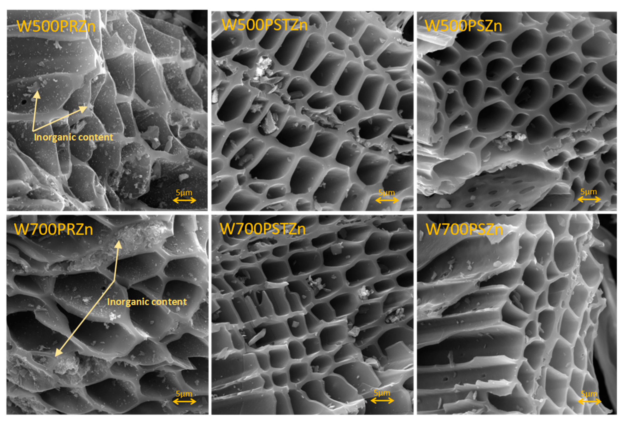
32]. The order of wet impregnation and pyrolysis significantly influences the physicochemical properties of the biochar composites such the pore structure and the specific surface area, SEM analysis indicated that the pre-treatment followed by pyrolysis induces catalyzed carbonization of the biomass, formation of pores and considerable surface area[
34]. This contrasts with post-treatment of the pyrolyzed samples, containing less unevenly distributed inorganic particles/larger crystal clusters resulted in blocking the pores and reduce the specific surface area (
Figure 4). Wet impregnation modification facilitated the introduction of higher concentrations of metals, leading to the formation of metal oxides on the biochar surface and an improvement in the porous structure. Interestingly, this comparative study of the ecotoxicological characteristics of Zn-decorated biochar prepared by either pretreatment of the biomass or post-treatment of the biochar demonstrated that the final biochar@Zn were found distinctly different [
34], for example post-treatment led to biochar@Zn with higher content of polyaromatic hydrocarbons and thus more toxicity. It follows that a comparative study of the method of preparation of reductive composite catalysts could be an issue when considering CO
2 methanation.
In recent studies, some of the authors [
17,
30] reported the synthesis of biochar/bimetallic nanocatalyst composites by mixing biomass into two metal nitrate solutions via a wet impregnation method followed by pyrolysis. SEM results revealed a spacious porous structure, with metal nanoparticles uniformly dispersed on the surface. XRD analysis confirmed the presence of a bimetallic alloy, verifying the successful loading of metal nanoparticles onto the biochar substrate.
3. Case studies for catalyzed CO2 methanation
Research on biochar-based composite materials for catalyzing carbon dioxide methanation reveals the critical factors of temperature, pressure, and gas composition on CO
2 conversion rates and CH
4 selectivity. The preparation, involved pre-treatment/activation, nanoparticle modifications and pyrolysis process parameters (temperature, flowrate, heat rate, residence time), play a key role in incorporating specific elements or achieve surface modifications. In
Table 1, we summarize the literature on some biochar-based composites for CO
2 methanation. The % CO
2 conversion and the % CH
4 selectivity were calculated according to Eqs. (3)-(4), where the subscripts “in” and “out” represent the participating gas inlet and gas outlet quantities, respectively.
3.1. The role of biochar composite preparation in CO2 methanation
The preparation of modified biochar composite materials typically involves a multi-step process, with variations in pre-treatment and pyrolysis steps as illustrated in
Table 1. González-Castaño
et al. [
35] introduced the infiltration of silica gel as a template into sucrose, followed by three rounds of impregnation and calcination to get biochar-support, and subsequent calcination and impregnation steps to produce Ni-Fe bimetallic catalysts. Renda
et al. [
36] emphasized biochar modification as a distinct step, involving pyrolysis under nitrogen and activation with CO
2, leading to impregnation of CeO
2 and eventual preparation of nickel catalysts. Wang
et al. [
39] focused on the in-situ pyrolysis process for nitrogen-doped biochar, utilizing
Pinus sylvestris as biomass, urea as a nitrogen precursor, and NaHCO
3 for activation, followed by the loading of ruthenium catalysts.
For the pyrolysis steps, regardless of the single metal catalyst Ni/biochar composite [
33], the biomass-soaked mixture was first calcined in N
2 at 400 °C for 2 h and then in H
2 at 400 °C for an additional period of 2 h. For bimetallic catalyst NiFe/biochar composite [
35] was obtained by a second pyrolysis of the biochar-soaked mixture, conducted at 300 °C for 8 hours, and under N
2/H
2 gas mixture stream. It was observed that the temperature set during the second pyrolysis did not exceed that used in the initial pyrolysis step.
3.2. Effect of surface basic sites
Considering that CO
2 is weakly acidic, the basic groups on the surface of carbonaceous materials play a significant role for the adsorption/activation of CO
2. Santos
et al. [
37] preparaed Na/Pt-biochar composites using alkali metals as the latter can change the electronic structure of the Pt-biochar, thus improving CO
2 adsorption on the Pt catalyst, and create more new basic sites for CO
2 activation.
In a related study, Mei
et al. [
33] highlighted the importance of acid-soluble inorganics and water-soluble inorganics over the biochar-supported Ni catalyst for methanation reaction at 1 MPa and 400 °C for 10 h. The authors emphasized the role of alkaline inorganic on the biochar surface. Surface modification was performed through pretreatment to inhibit acid-soluble inorganics and water-soluble inorganics on biochar, respectively. The results showed that nickel-loaded biochar without pretreatment resulted in higher CO
2 conversion, indicating that acid-soluble inorganics dominate the performance of biochar, while water-soluble inorganics also play a role, but at lower extent. Acid-soluble inorganics can not only promote the interaction of Ni/support, but also increase the concentration of basic sites on the catalyst surface.
Wang et.al [
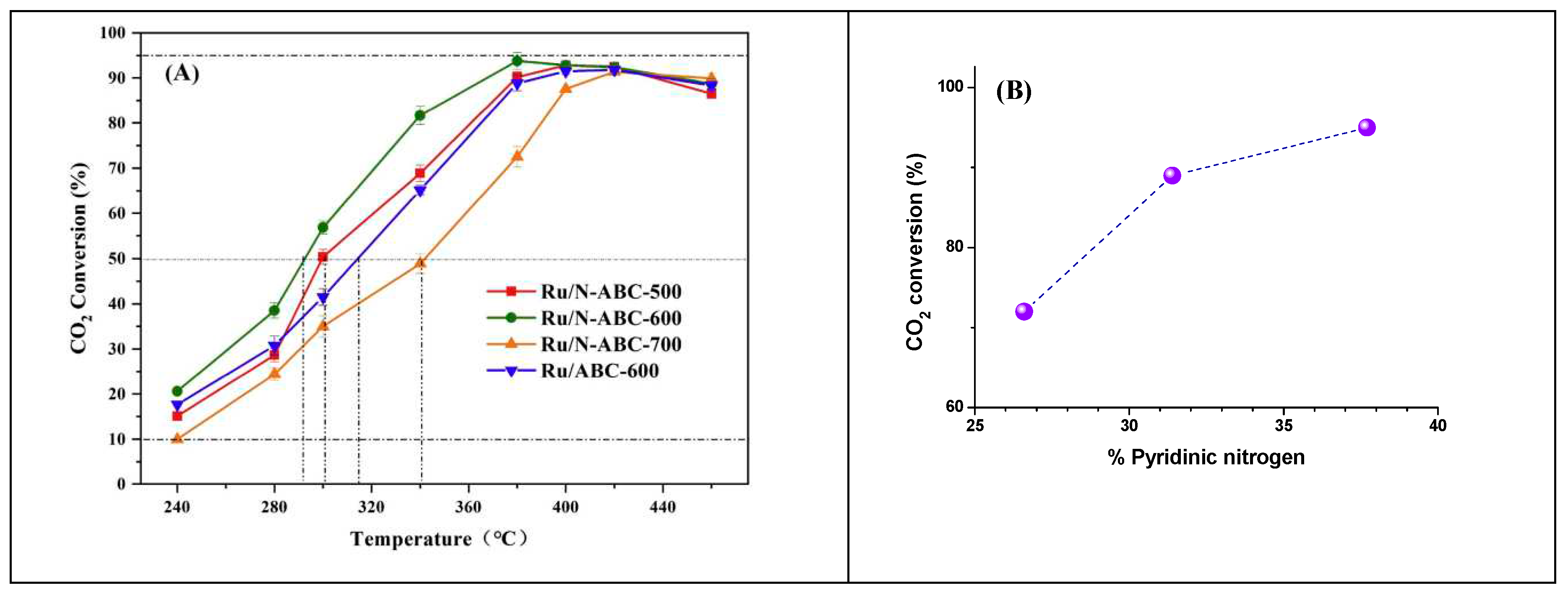
39] investigated the role of the three types of nitrogen on the surface alkalinity of biochar composites. They achieved CO
2 conversion of 93.8% and CH
4 selectivity of 99.7% using high-performance of Ru/N-ABC-600. It was emphasized that the high pyridinic nitrogen content and the surface basicity of the catalyst are the key factors for superior performance, as depicted in
Figure 5. Indeed, the CO
2 conversion levels off at 380 °C with a clear correlation with the extent of pyridinic nitrogen type in the biochar support, determined by N1s peak-fitting in XPS. The incorporation of nitrogen atoms, especially pyridinic-N, enhance the electronic effects and alkalinity, promoting H
2 dissociation and CO
2 adsorption. Metal doping represents an indispensable methodology enhancing the performance and stability of Ni-based catalysts supported on biochar.
González-Castagno
et al. [
35] used the CO
2-thermal programmed desorption (TPD) to determine the surface basic sites, as well as the reaction rates and turnover frequencies (TOFs), which was calculated using :
The authors determined TOFs by considering Ni sites dispersed on the surface of the catalysts, and compared in this way Ni/Al
vs NiFe/Al, Ni/biochar
vs NiFe/biochar, and found that surface basicity contributes to the activation and adsorption of CO
2 which is favoured by the increase in basic sites (
Table 2). Therefore, the extent of basic sites was correlated with catalytic performances, however within the set of samples having the same support. If one compares the catalysts loaded on different supports, the basic site density promotes CO
2 adsorption, but not necessarily the TOF. Indeed, NiFe/biochar adsorbs less CO
2 than NiFe/Al but performs much better than the latter when one considers TOF ; this is ascribed to the remarkable specific surface area imparted par the underlying biochar (712 >> 162 m²/g).
Following the successful bimetallic Ni/Ce-biochar composites synthesis, Di Stasi
et al. [
40] considered replacing the Ce catalyst with an N-catalyst (using urea) over Ni-biochar support. The addition of nitrogen imparted higher catalytic activity due to the higher pyridinic-N content introduced by urea doping, and nitrogen-containing functional groups content remained relatively constant under the operational conditions. However, N-catalyst did not significantly improve the dispersion of Ni nanoparticles as CeNi did.
3.3. Effect of metal loading
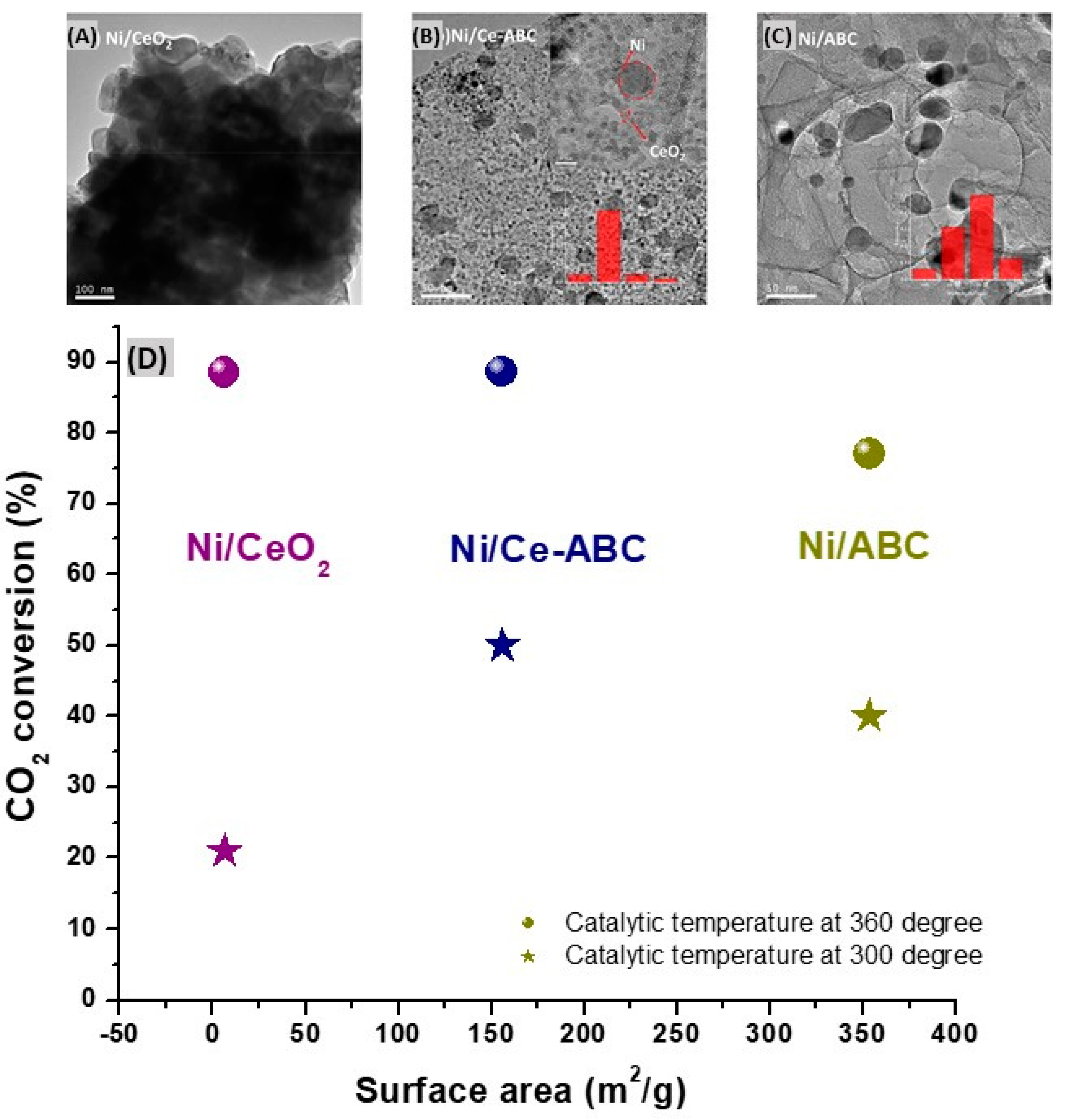
Ni/ABC almost retains the specific surface area of the pristine biochar (more than 350 m
2/g) ; the specific surface area of the catalyst Ni/CeO
2 is only 6.4 m
2/g. After in-situ modification of cerium, the specific surface area of the Ni/Ce-ABC is almost half that of Ni/ABC about 155.6 m
2/g. However, the modification of Ce also helped to improve the nanoparticle dispersion on the biochar and limits the growth of nickel species, reducing the average size of Ni from 20 nm for Ni/ABC to 5-12 nm in the case of Ni/Ce-ABC. Of utmost importance, Ni nanoparticles are evenly distributed on the support. The Ni/Ce-ABC composite showed better performance at relatively lower temperature (300 °C), which can be mainly attributed to the uniform dispersion of nickel species and CeO
2 particles, providing more alkaline sites for CO
2 adsorption and activation. When the temperature increases to 360 °C, the CO
2 conversion % of the three catalysts is almost the same, which may be due to the basically same Ni content in all composites (
Figure 6). The reaction activity of the catalyst under high temperature mainly depends on Ni species.
Renda et al. [
36] further studied the effect of CeO
2 doping amount on Ni-biochar (obtained from wheat straw) on CO
2 methanation and stability.
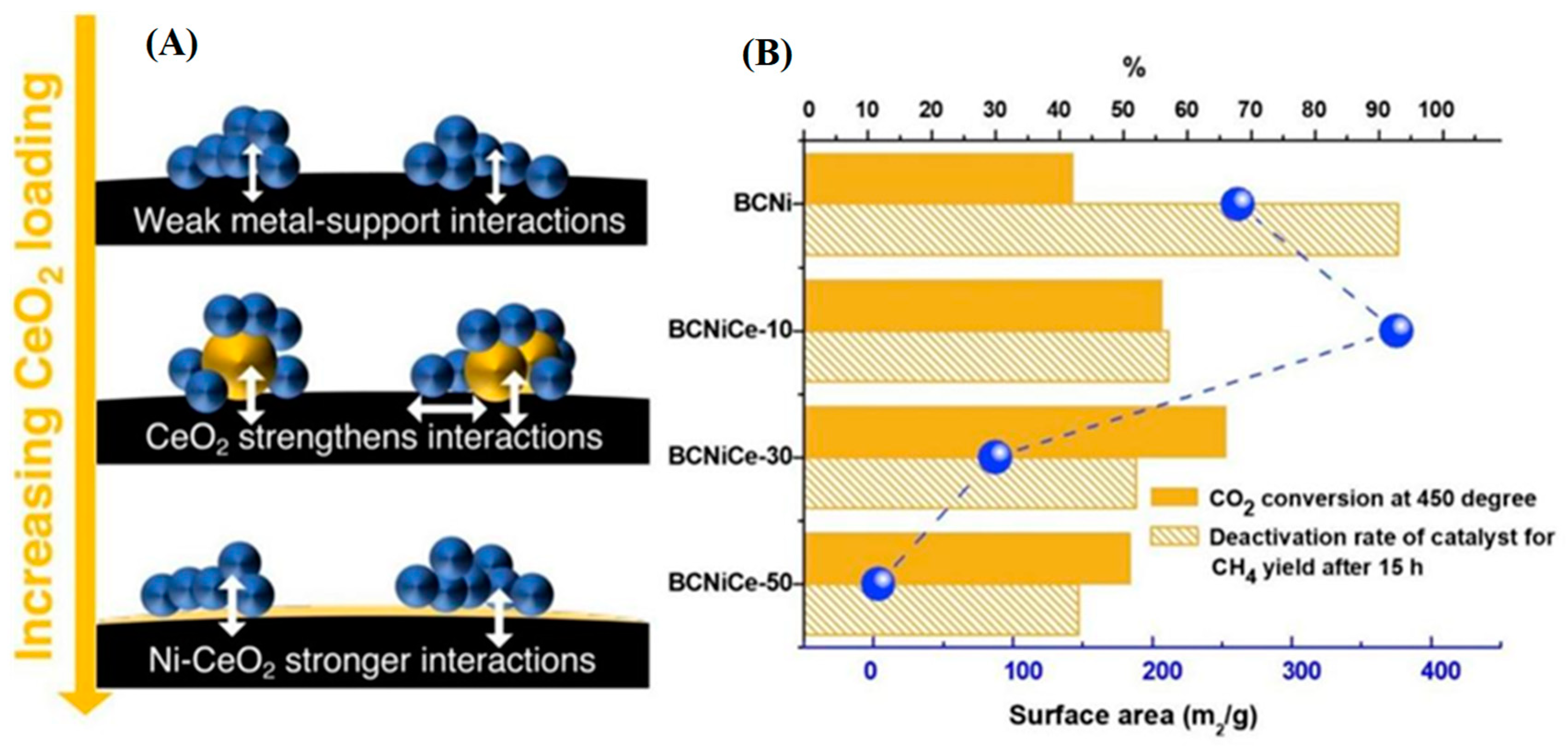
Figure 7 shows that the addition of CeO
2 enhances catalytic performance by promoting CO
2 activation and reduces the deactivation rate of Ni-biochar support for CH
4 yield, indicating that CeO
2 strengthens Ni-support interaction to increase catalyst life. The specific surface area of BC may be tuned using CeO
2 ; adding a low concentration (10 wt. %) of metal nanoparticles built a higher specific surface area and micro-pores volume. In contrast, exceeding a certain amount (50 wt. %), the metal nanoparticles completely coat the biochar and block its pores, therefore resulting in a very low specific surface area, and consequently lower CO
2 conversion rate.
In another study [
40], the same research group compared different concentrations of Ce and Ni on the wheat straw biochar substrate and revealed that a biochar-based composite with 30% Ce and 20% Ni exhibited optimal carbon dioxide conversion (>90%), and methane selectivity (~100%) at 350 °C and 1.0 Mpa.
Gamal
et al. [
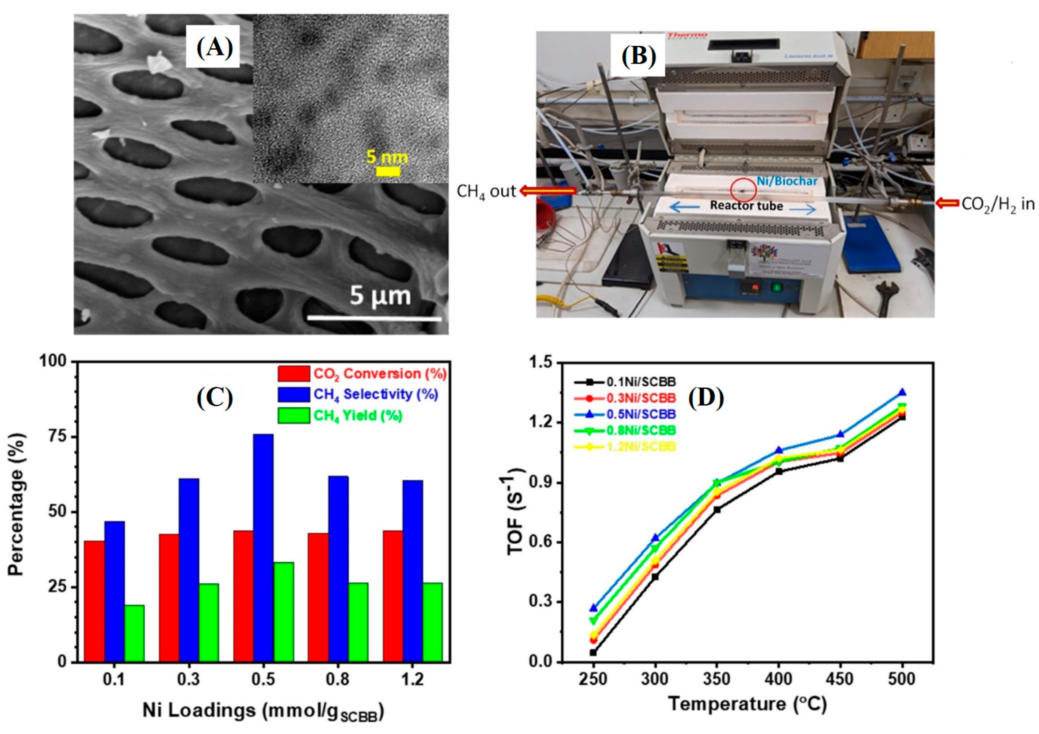
https://doi.org/10.1016/j.mtsust.2023.100627] have developed an interesting eco-friendly sugarcane bagasse biochar/nickel sustainable catalyst (
Figure 8a) for the thermal catalytic CO
2 methanation (
Figure 8b). The biochar-supported Ni catalyst was prepared by pyrolysis of 0.5 mmol Ni-impregnated gram of biomass has exhibited highest CO
2 conversion efficiency (
Figure 8c,d) when tested in the 250-550 °C temperature range. This was ascribed to the good dispersion of ~3 nm-sized Ni particles on the biochar surface, in sufficient concentration. Further studies have revealed that highest CH
4 selectivity (
Figure 8c) is observed at 400 °C and 1 bar pressure (44% CO
2 conversion; 76% methane selectivity; 34% methane yield). The authors have found the TOF to be highest for biochar made from 0.5 mmol nickel salt per gram of SCB. The 0.5Ni/SCBB catalyst enabled the transformation of a large number of molecules, within a short period of reaction time, regardless the operating working temperature (
Figure 8d). Moreover, the Ni/biochar optimized catalyst was found to be highly stable and could be re-used for the same process. The green and low-cost strategy devised by the authors could be extended to other reductive catalysts.
4. Challenge and prospects of biochar@catalyst composites in CO2 methanation
In recent years, biochar-based composites have been rapidly developed for CO
2 capture and [
41,
42,
43]. The structural characteristics and surface functional groups of biochar supports are crucial for the effective reduction of CO
2 to CH
4, and the fabrication and modification of biochar@catalyst composite materials are also critical. As mentioned earlier, metal-loaded catalysts exhibit broad practical prospects due to their simple preparation methods, superior catalytic performance, and good stability. Among them, nickel-based catalyst is extensively applied and researched, owing to their outstanding CO
2 methanation performance and facilitate recovery, thus holding significant potential for energy utilization. However, metal nanoparticles tend to aggregate on the surface of biochar, and the CO
2 methanation process requires relatively high temperatures and high pressures. Thus, in order to better satisfy industrial application requirements, researchers need to conduct further studies and developments to improve the performance of composite catalysts, enabling large-scale green energy utilization under mild reaction conditions. Furthermore, encouraging the production of carbon-containing materials from agricultural waste is a promising approach, which contributes to the creation of environmentally friendly and nearly cost-free support materials while reducing the adverse environmental impact of agricultural waste. Therefore, biochar-based composite materials show the potential and prospects as catalysts for environmental remediation in the future.
Conclusion
In this review, we firstly presented the fabrication and modification of biochar-immobilized nanoparticle catalyst composites and focus on the conversion of biomass into valuable products with thermochemical methods. The activation processes and metal nanoparticle loading are key steps for the modification of biochar@catalysts composite materials, suggesting improving the physicochemical properties, such as graphitization, surface functional groups, and active sites. It is notable that the pore structure of biochar-supported composites are impacted by the sequence of wet impregnation and pyrolysis. Secondly, in the application CO2 methanation with biochar@catalyst composites, the alkaline sites on the material surface are closely linked to CO2 adsorption. However, whenever the extent of basic sites decreases, a high specific area is required to counterbalance the loss of basic sites. In this respect, biochar is shown to provide an excellent alternative to traditional supports such as alumina. Concerning metal loading onto the biochar, although it might induce a decrease in the surface area, there is an increase in micropore volume thus facilitating easier gas molecule diffusion. The introduction of metal nanoparticles also contributes to an increase in the active sites, and bimetallic catalyst nanoparticles effectively mitigate the aggregation of nanoparticles, achieving higher dispersion on the composite material surface, thereby enhancing CO2 conversion rates and CH4 selectivity.
These research findings offer reliable insights for the preparation and modification of biochar@catalyst composite materials, facilitating further optimization of such products to CO2 methanation applications.
Author Contributions
Conceptualization (M.M.C., A.A.B;); Methodology (M.M.C., M.T. A.G.); Validation (all authors); Writing–Original Draft (M.T., A.G., A.K.B., M.M.C.); Writing—Review and Editing (all authors); Supervision (M.M.C.); Funding Acquisition (M.M.C., A.K.B., M.T., A.A.B.). All authors have read and agreed to the published version of the manuscript.
Acknowledgements for Funding
This work was supported by (i) China Scholarship Council for the provision of PhD scholarship to M. Tang (No 202008310221). (ii) the Qatar National Research Fund (QNRF, a member of the Qatar Foundation) through the National Priority Research Program Grant (NPRP) NPRP13S-0117-200095, (iii) Qatar University through an International Research Collaboration Co-Fund grant, IRCC-2021-015, and (iv) Wallonie Bruxelles International (WBI) for the provision of a grant to A.K. Bhakta through “Bourse WBI Excellence World” (No Imputation 101386, Article Budgétaire 13 33.01.00.07).
References
- M.W. Jones, G.P. Peters, T. Gasser, R.M. Andrew, C. Schwingshackl, J. Guetschow, R.A. Houghton, P. Friedlingstein, J. Pongratz, C. Le Quere, Scientific Data 10 (2023). [CrossRef]
- D.D. Zhu, J.L. Liu, S.Z. Qiao, Adv. Mater. 28 (2016) 3423-3452. [CrossRef]
- T.A. Jacobson, J.S. Kler, M.T. Hernke, R.K. Braun, K.C. Meyer, W.E. Funk, Nature Sustainability 2 (2019) 691-701.
- N. Mac Dowell, P.S. Fennell, N. Shah, G.C. Maitland, Nature Climate Change 7 (2017) 243-249. [CrossRef]
- B. Dziejarski, J. Serafin, K. Andersson, R. Krzyzynska, Materials Today Sustainability 24 (2023). [CrossRef]
- S. Chaemchuen, O.V. Semyonov, J. Dingemans, W. Xu, S. Zhuiykov, A. Khan, F. Verpoort, Chemistry Africa 2 (2019) 533-549.
- M. Zhang, Y. Gao, Y. Mao, W. Wang, J. Sun, Z. Song, J. Sun, X. Zhao, Chemical Engineering Journal 451 (2023) 138616.
- L. Song, H. Wang, S. Wang, Z. Qu, Applied Catalysis B: Environmental 322 (2023) 122137.
- Y. Xie, J. Wen, Z. Li, J. Chen, Q. Zhang, P. Ning, J. Hao, ACS Materials Letters 5 (2023) 2629-2647.
- M.I. Malik, I.E. Achouri, N. Abatzoglou, F. Gitzhofer, Fuel Processing Technology 245 (2023) 107748.
- I. Hussain, A.A. Jalil, S.M. Izan, M.S. Azami, K. Kidam, N. Ainirazali, A. Ripin, Chem. Eng. Sci. 229 (2021). [CrossRef]
- X. Guo, A. Traitangwong, M. Hu, C. Zuo, V. Meeyoo, Z. Peng, C. Li, Energy & Fuels 32 (2018) 3681-3689. [CrossRef]
- F. Mateus, P. Teixeira, J.M. Lopes, C. Henriques, C. Bacariza, Energy & Fuels (2023).
- J. Omiri, Y. Snoussi, A.K. Bhakta, S. Truong, S. Ammar, A.M. Khalil, M. Jouini, M.M. Chehimi, Colloids And Interfaces 6 (2022). [CrossRef]
- L. Boubkr, A.K. Bhakta, Y. Snoussi, C.M. Da Silva, L. Michely, M. Jouini, S. Ammar, M.M. Chehimi, Catalysts 12 (2022). [CrossRef]
- H. Bayoka, Y. Snoussi, A.K. Bhakta, M. El Garah, A.M. Khalil, M. Jouini, S. Ammar, M.M. Chehimi, J. Anal. Appl. Pyrolysis 173 (2023). [CrossRef]
- M. Tang, Y. Snoussi, A.K. Bhakta, M. El Garah, A.M. Khalil, S. Ammar, M.M. Chehimi, Environ. Res. 232 (2023) 116232-116232. [CrossRef]
- A.K. Sharma, P.K. Ghodke, N. Goyal, P. Bobde, E.E. Kwon, K.Y.A. Lin, W.-H. Chen, Bioresour. Technol. 387 (2023). [CrossRef]
- C. Wen, T. Liu, D. Wang, Y. Wang, H. Chen, G. Luo, Z. Zhou, C. Li, M. Xu, Prog. Energy Combust. Sci. 99 (2023). [CrossRef]
- R.K. Mishra, D.J.P. Kumar, A. Narula, S.M. Chistie, S.U. Naik, Fuel 343 (2023). [CrossRef]
- R. Ahuja, A. Kalia, R. Sikka, P. Chaitra, Acs Omega 7 (2022) 45825-45836. [CrossRef]
- C. Xia, A. Pathy, B. Paramasivan, P. Ganeshan, K. Dhamodharan, A. Juneja, D. Kumar, K. Brindhadevi, S.-H. Kim, K. Rajendran, Fuel 311 (2022). [CrossRef]
- S. Yu, L. Wang, Q. Li, Y. Zhang, H. Zhou, Materials Today Sustainability 19 (2022). [CrossRef]
- C. Sun, T. Chen, Q. Huang, M. Zhan, X. Li, J. Yan, Chem. Eng. J. 380 (2020). [CrossRef]
- N. Iberahim, S. Sethupathi, M.J.K. Bashir, R. Kanthasamy, T. Ahmad, Sci. Total Environ. 805 (2022). [CrossRef]
- D. Feng, D. Guo, Y. Zhang, S. Sun, Y. Zhao, G. Chang, Q. Guo, Y. Qin, Chem. Eng. J. 409 (2021). [CrossRef]
- Z. Tang, J. Gao, Y. Zhang, Q. Du, D. Feng, H. Dong, Y. Peng, T. Zhang, M. Xie, Fuel Process. Technol. 241 (2023). [CrossRef]
- J.M. Jabar, Y.A. Odusote, Y.T. Ayinde, M. Yilmaz, Results In Engineering 14 (2022). [CrossRef]
- T.-B. Nguyen, Q.-M. Truong, C.-W. Chen, R.-a. Doong, W.-H. Chen, C.-D. Dong, Bioresour. Technol. 346 (2022). [CrossRef]
- Y. Snoussi, I. Sifaoui, M. El Garah, A.M. Khalil, M. Jouini, S. Ammar, J.L. Morales, M.M. Chehimi, Waste Manage. (Oxford) 155 (2023) 179-191. [CrossRef]
- E. Prabakaran, K. Pillay, H. Brink, Materials Today Sustainability 18 (2022). [CrossRef]
- Z. He, Y. Zhang, J. Lv, S. Zhou, J. Niu, Z. Li, X. Wang, T. Wagberg, G. Hu, Journal Of Water Process Engineering 50 (2022). [CrossRef]
- Z. Mei, D. Chen, G. Yuan, R. Zhang, Fuel 349 (2023). [CrossRef]
- M. Marcinczyk, P. Krasucka, A. Bogusz, B. Tomczyk, W. Duan, B. Pan, P. Oleszczuk, Chemosphere 315 (2023). [CrossRef]
- M. Gonzalez-Castano, C. Morales, J.C. Navarro de Miguel, J.H. Boelte, O. Klepel, J.I. Flege, H. Arellano-Garcia, Green Energy & Environment 8 (2023) 744-756. [CrossRef]
- S. Renda, C. Di Stasi, J.J. Manya, V. Palma, Journal Of Co2 Utilization 53 (2021). [CrossRef]
- J.L. Santos, L.F. Bobadilla, M.A. Centeno, J.A. Odriozola, C-Journal Of Carbon Research 4 (2018). [CrossRef]
- X. Wang, M. Yang, X. Zhu, L. Zhu, S. Wang, Applied Energy 280 (2020). [CrossRef]
- X. Wang, Y. Liu, L. Zhu, Y. Li, K. Wang, K. Qiu, N. Tippayawong, P. Aggarangsi, P. Reubroycharoen, S. Wang, Journal Of Co2 Utilization 34 (2019) 733-741. [CrossRef]
- C. Di Stasi, S. Renda, G. Greco, B. Gonzalez, V. Palma, J.J. Manya, Sustainability 13 (2021). [CrossRef]
- M. Karimi, M. Shirzad, J.A.C. Silva, A.E. Rodrigues, Journal Of Co2 Utilization 57 (2022). [CrossRef]
- L. Cao, X. Zhang, Y. Xu, W. Xiang, R. Wang, F. Ding, P. Hong, B. Gao, Sep. Purif. Technol. 287 (2022). [CrossRef]
- A.N. Shafawi, A.R. Mohamed, P. Lahijani, M. Mohammadi, Journal Of Environmental Chemical Engineering 9 (2021). [CrossRef]
|
Disclaimer/Publisher’s Note: The statements, opinions and data contained in all publications are solely those of the individual author(s) and contributor(s) and not of MDPI and/or the editor(s). MDPI and/or the editor(s) disclaim responsibility for any injury to people or property resulting from any ideas, methods, instructions or products referred to in the content. |
© 2023 by the authors. Licensee MDPI, Basel, Switzerland. This article is an open access article distributed under the terms and conditions of the Creative Commons Attribution (CC BY) license (http://creativecommons.org/licenses/by/4.0/).
