1. Introduction
Micro-electro-mechanical systems (MEMS), also known as microsystems technology, is a technology that integrates mechanical and electronic components on a single chip and is manufactured using microfabrication techniques. The key components of MEMS include sensors, actuators, and microelectronics [
1,
2,
3]. Microactuators are used to convert non-mechanical input energy into mechanical output energy. There are various types of microactuation technologies, with the most used being piezoelectric, magnetic, thermal, electrochemical, and electrostatic actuation [
4,
5,
6,
7]. Among these actuation mechanisms, electrostatic actuation is the most widely used driving technology. Electrostatic actuators do not require additional components such as coils or iron cores, and not rely on special materials like alloys or piezoelectric ceramics, which are not compatible to the standard CMOS manufacturing process. [
8,
9,
10,
11,
12,
13,
14,
15,
16] It is less influenced by scaling and advantageous for the applications of ultra-large-scale integrated circuit transducer [
17].
One of the most common electrostatic actuators is the comb-drive actuator. The comb-drive actuator consists of two interdigitated comb microstructures, one of which is fixed, and the other is connected to a flexible suspension microstructure. When applying a voltage difference between the comb microstructures, the movable comb microstructures can be actuated due to the electrostatic forces. The comb-drive actuator is widely utilized to achieve large displacement at low driving voltage. It was originally developed by Tang et al. in 1989 [
18]. The applications of this comb-drive actuator are included but not limited to resonators [
19,
20,
21,
22], optical shutters [
23], micro-mechanical gears [
24,
25], micro grippers [
26,
27], and micro tweezers [
28]. This voltage-controlled comb-drive actuators are applied the lateral electrostatic forces to control the displacement of the movable comb teethes, making them attractive for micro-positioning applications in two-axis or three-axis micro-stages [
29,
30,
31]. The advantages of using electrostatic comb-drive actuators are low power consumption, simplified electronic control, and easy sensing mechanism based on capacitance [
32]. To achieve the above-mentioned merits, the stability of actuation system is a key role for high-performance actuator and sensor applications. The motion state of comb-driver can be restored by using spring microstructure to make the system stable, continuous, and reversible. Thus, the suspension microstructure is required to have a lower spring constant in the desired displacement direction and a higher spring constant in the vertical direction. The electrostatic force increases along with an increment of the number of comb fingers and a decrement of the gap between them. In addition to these parameters, the length of the suspension microstructure is also a variable to achieve larger displacement at lower driving voltage.
In view of above points, we present a design of electrostatic comb actuator (ECA) to improve and investigate its actuation performance. The proposed ECA is composed of two set of interdigitated comb microstructures, the inner combs are fixed to form the fish-bone microstructures and the outer combs are movable and connected to crab-leg flexure beams microstructures. This study aims to achieve larger displacements at lower driving voltage by varying different design parameters. The working principle is initially discussed, followed by an exploration of the impact of different comb shapes and the intersection angles of crab-leg flexure beams on system performance.
2. Design and Method
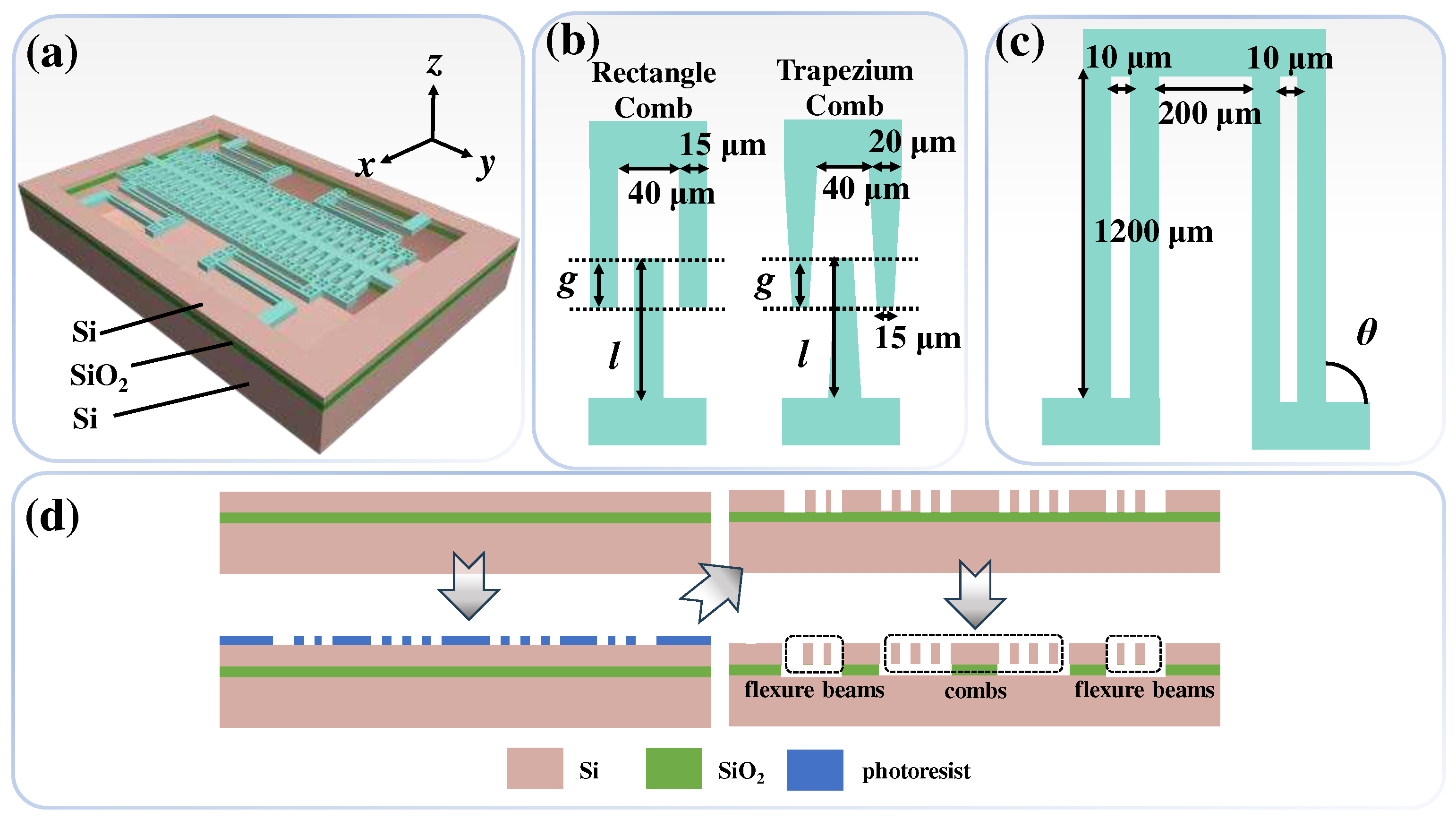
Figure 1(a) shows the schematic diagram of the proposed ECA. The configurations of comb fingers are illustrated in
Figure 1(b), which are compared between the rectangular and trapezoidal comb shapes including the relative geometric parameters. The variable
l and
g parameters represent the comb finger length and the overlap between comb fingers, respectively. The space between comb fingers is 40 μm, and the linewidth of the rectangular combs is 15 μm. For trapezoidal combs, the bottom linewidth is 20 μm, and the top linewidth is 15 μm.
Figure 1(c) illustrates the parameters of the crab-leg flexure beams. The beam length is 1200 μm, the space between adjacent crab-leg flexure beams is 10 μm, and the space between crab-leg flexure beam groups is 200 μm. The variable parameter is the intersection angles of crab-leg flexure beams, which is defined as
θ. Thus, the impacts of different
l,
g values, and crab-leg flexure beams angles are compared and discussed as
θ = 45°, 60°, and 90°.
Figure 1(d) illustrates the fabrication process flow of the proposed ECA. First, a silicon-on-insulator (SOI) wafer is prepared and cleaned. The thicknesses of device layer, insulation layer, and handle layer are 50 μm, 1 μm, and 300 μm, respectively. Second, the pattern of ECA is defined by using maskless photolithography process. Third, the microstructures of ECA including fishbone combs and crab-leg flexure beams are etched by using deep reactive ion etching (DRIE) process. Finally, the microstructures of ECA are released by using vapor hydrogen fluoride (VHF) to make the ECA microstructures suspension.
The proposed ECA is driven by electrostatic force generated from the voltage difference applied between the fixed and movable combs. The operation mechanism of the ECA is based on the force balance between the electrostatic force and the mechanical restoring force generated by the crab-leg flexure beams. The driving voltage is applied to the movable combs and the fixed combs are anchored and connected to grounding electrode. The applied voltage difference between the combs leads to the deflection of the movable comb fingers caused from the generation of electrostatic force. This electrostatic force provides an actuation in the movable direction of the comb fingers. This displacement results in a change in the overlapping area, thereby causing a variation in the capacitance value. The position of the movable comb finger is controlled by a balance between the electrostatic force and the mechanical restoring force of the crab-leg flexure beams. The change in capacitance is given by the following equation [
31].
where
x represents the displacement of the movable combs,
N is the number of comb finger,
ε0 is relative dielectric constant,
w is space between comb fingers,
t is time, and
g is the interdigitated distance between the comb fingers. The electrostatic force in the
x-axis direction is given by the following equation.
where
V is the driving bias voltage. The displacement of the movable comb finger (
x) equals electrostatic force (
Fe) divided by the mechanical stiffness constant of the the crab-leg flexure beams (
K), i.e.,
x =
Fe/
K.
K can be expressed by
where
E is the electric field intensity,
l is the comb finger length, and
Wc is the equivalent comb finger width. Therefore, the displacement is given by the following equation.
It is because that the structural material of ECA is silicon, which shows excellent mechanical and electrical properties, and can be further modified through doping [
2]. In this study, the properties of the used silicon material are Young's modulus of 160 GPa, Poisson ratio of 0.22, density of 2320 kg/m
3, and dielectric constant of 4.5, respectively.
3. Results and Discussions
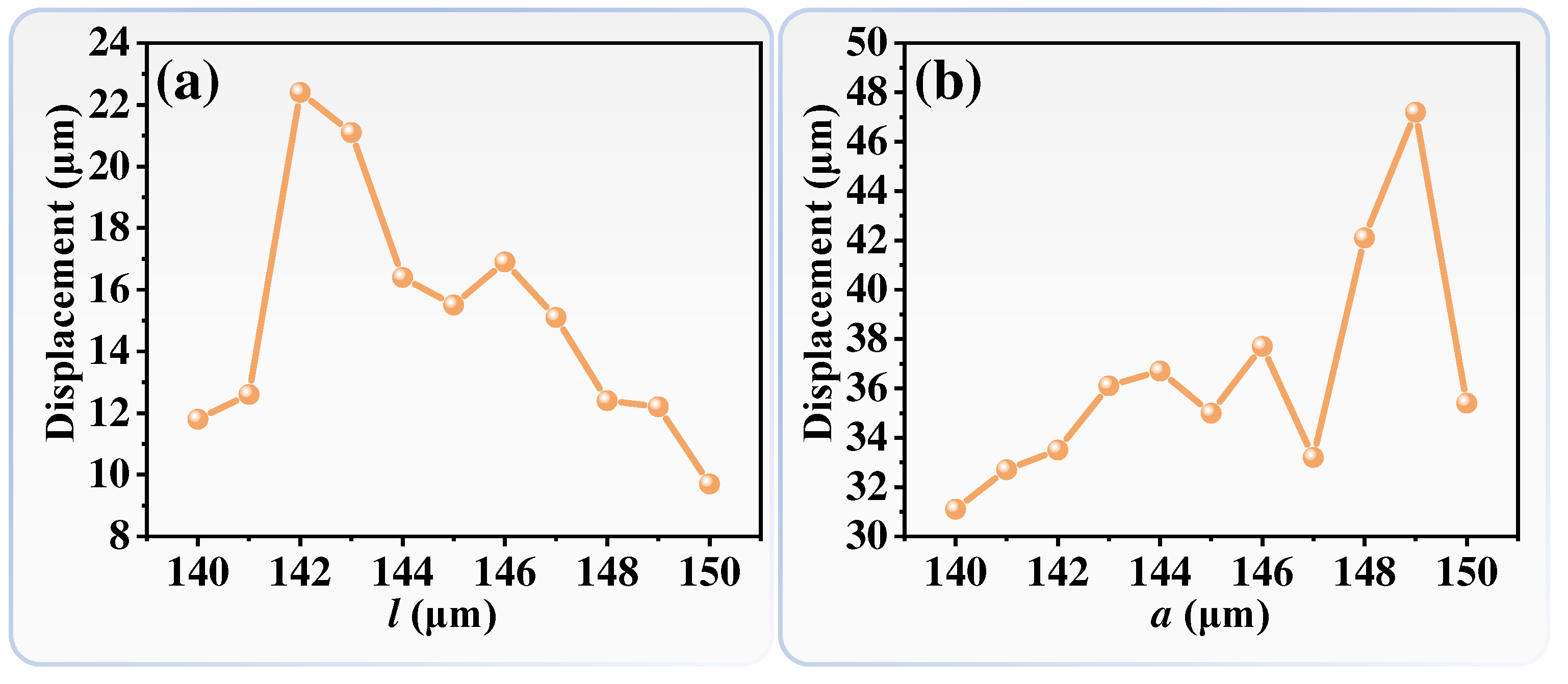
Figure 2 shows relationships of displacements and ECA with different comb finger lengths under a driving DC bias voltage of 100 volts.
Figure 2(a) and (b) represent the comb finger with rectangular and trapezoidal shapes, respectively. It can be observed that for both rectangular and trapezoidal comb shapes, the displacement of the combs shows a trend of initially increasing and then decreasing along with the increment of the comb finger length. According to Eq. (4), the displacement of the comb finger is related to the comb finger length (
l), the electric field intensity (
E), and the driving bias voltage (
V). When the driving bias voltage (
V) keeps as constant, the electric field intensity (
E) will be increased along with the increment of the comb finger length (
l). Initially, the influence of the comb finger length is dominant that the comb finger displacement will be gradually increased. However, as the influence of the electric field intensity becomes dominant that the comb finger displacement is gradually decreased. Additionally, the different comb shape such as rectangle and trapezoid, has different equivalent comb finger width (
Wc), which will result in the variations of the turning points in the displacement.
To further investigate the influence of different crab-leg flexure beam configurations on the stability of ECA,
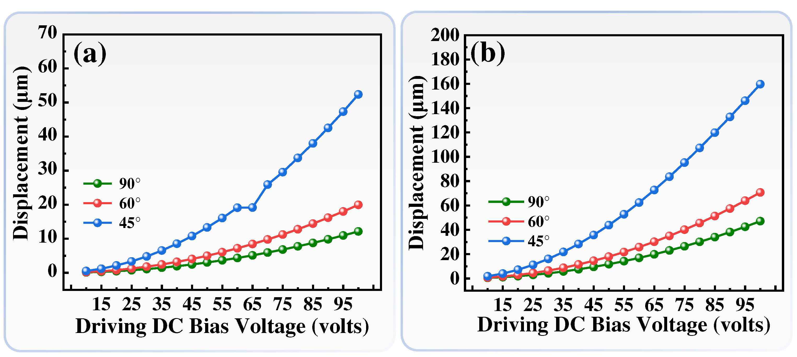
Figure 3 shows the relationships of comb fingers displacements and driving bias voltages for ECA crab-leg flexure beams with different
θ values (45°, 60°, and 90°), while keeping the comb finger length (
l) as constant as 149 μm.
Figure 3(a) and (b) represent the comb finger with rectangle and trapezoid shape, respectively. The trend of comb fingers displacements and bias voltages exhibits a quadratic relationship, which is consistent with the Eq. (4). As the intersection angle of crab-leg flexure beams decreases, the displacement of the ECA increases under the same DC bias voltage. When the ECA with rectangle combs is applied a driving DC bias voltage of 100 volts, the displacements are 52.36 μm, 19.95 μm, and 12.15 μm for
θ = 45°, 60°, and 90°, respectively. The displacement of crab-leg flexure beams with
θ = 45° is 2.6-fold and 4.3-fold compared to that with
θ = 60° and
θ = 90°, respectively. While the ECA with trapezoid combs is applied a driving DC bias voltage of 100 volts, the displacements are 159.69 μm, 70.71 μm, and 47.12 μm for
θ = 45°, 60°, and 90°, respectively. The displacement of crab-leg flexure beams with
θ = 45° is 2.3-fold and 3.4-fold compared to that with
θ = 60° and
θ = 90°, respectively. To compare the ECA with trapezoid combs to that with rectangle combs, the displacements are enhanced 3.9-fold for
θ = 90°, 3.5-fold for
θ = 60°, and 3.0-fold for
θ = 45°, respectively. The ECA with trapezoid combs exhibits significantly larger displacement compared to the ECA with rectangle combs. When the ECA with rectangle combs and
θ = 45° is applied a DC bias voltage of 65 volts, the displacement of the ECA deviates from the quadratic trend. It is attributed to the structural instability of the ECA with
θ = 45°. Thus, to further investigate the relationships between ECA stabilities and crab-leg flexure beams angles in detail, the displacements along
x- and
y-axis are analyzed and discussed sequentially. That will impact the overall performance and reliability of the ECA device.
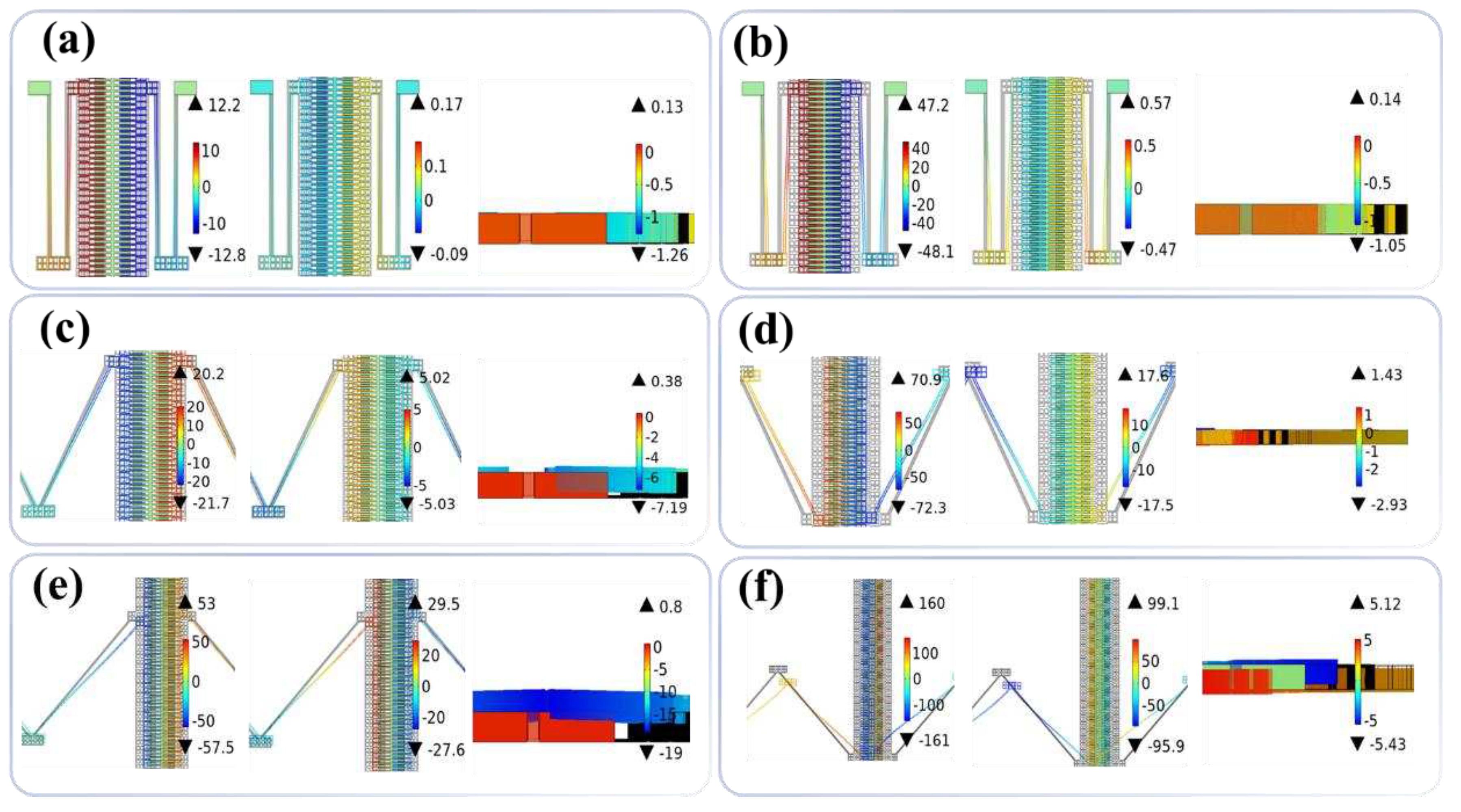
To better illustrate the influences of crab-leg flexure beams angles on the stability of the ECA, the energy field distributions of the ECA with rectangle and trapezoid combs along the
x-,
y-, and
z-axis directions are plotted in
Figure 4. The driving DC bias voltage is kept as constant as 100 volts.
Figure 4(a) and (b) show the ECA with rectangle and trapezoid combs under the condition of
θ = 90°, respectively. The ECA with rectangle combs exhibits maximum displacements of 12.8 μm in the
x-axis direction, 0.17 μm in the
y-axis direction, and 1.26 μm in the
z-axis direction. The maximum displacement of the ECA with rectangle combs in the
x-axis direction is 75.3-fold larger than that in the
y-axis direction and 10.16-fold larger than that in the
z-axis direction. While the ECA with trapezoid combs exhibits maximum displacements of 48.1 μm in the
x-axis direction, 0.57 μm in the
y-axis direction, and 1.05 μm in the
z-axis direction. Here, the maximum displacement of the ECA with trapezoid combs in the
x-axis direction is 84.4-fold larger than that in the
y-axis direction and 45.8-fold larger than that in the
z-axis direction.
Figure 4(c) and (d) show the ECA with rectangle and trapezoid combs under the condition of
θ = 60°, respectively. The ECA with rectangle combs exhibits maximum displacements of 21.7 μm in the
x-axis direction, 5.03 μm in the
y-axis direction, and 7.19 μm in the
z-axis direction. The maximum displacement of the ECA with rectangle combs in the
x-axis direction is 4.3-fold larger than that in the
y-axis direction and 3.0-fold larger than that in the
z-axis direction. While the ECA with trapezoid combs exhibits maximum displacements of 72.3 μm in the
x-axis direction, 17.6 μm in the
y-axis direction, and 2.93 μm in the
z-axis direction. The maximum displacement of the ECA with trapezoid combs in the
x-axis direction is 4.1-fold larger than that in the
y-axis direction and 24.7-fold larger than that in the
z-axis direction.
Figure 4(e) and (f) show the ECA with rectangle and trapezoid combs under the condition of
θ = 45°, respectively. The ECA with rectangle combs exhibits maximum displacements of 57.5 μm in the
x-axis direction, 29.5 μm in the
y-axis direction, and 19.0 μm in the
z-axis direction. The maximum displacement of the ECA with rectangle combs in the
x-axis direction is 1.9-fold larger than that in the
y-axis direction and 3.0-fold larger than that in the
z-axis direction. While the ECA with trapezoid combs exhibits maximum displacements of 161 μm in the
x-axis direction, 99.1 μm in the
y-axis direction, and 5.43 μm in the
z-axis direction. The maximum displacement of the ECA with trapezoid combs in the
x-axis direction is 1.6-fold larger than that in the
y-axis direction and 29.7-fold larger than that in the
z-axis direction. The higher stability of the ECA is defined by the greater difference between the displacements in the
x-axis direction and the
y/
z-axis directions. When
θ = 90°, the ECA exhibits the best stability. Conversely, when
θ = 45°, the stability of the ECA is the worst. Moreover, for the same crab-leg flexure beams angle, the ECA with trapezoid combs exhibits slightly better stability compared to that with rectangle combs. This suggests that the ECA with trapezoid combs possesses advantages of larger displacement and better stability compared to that with rectangle combs.
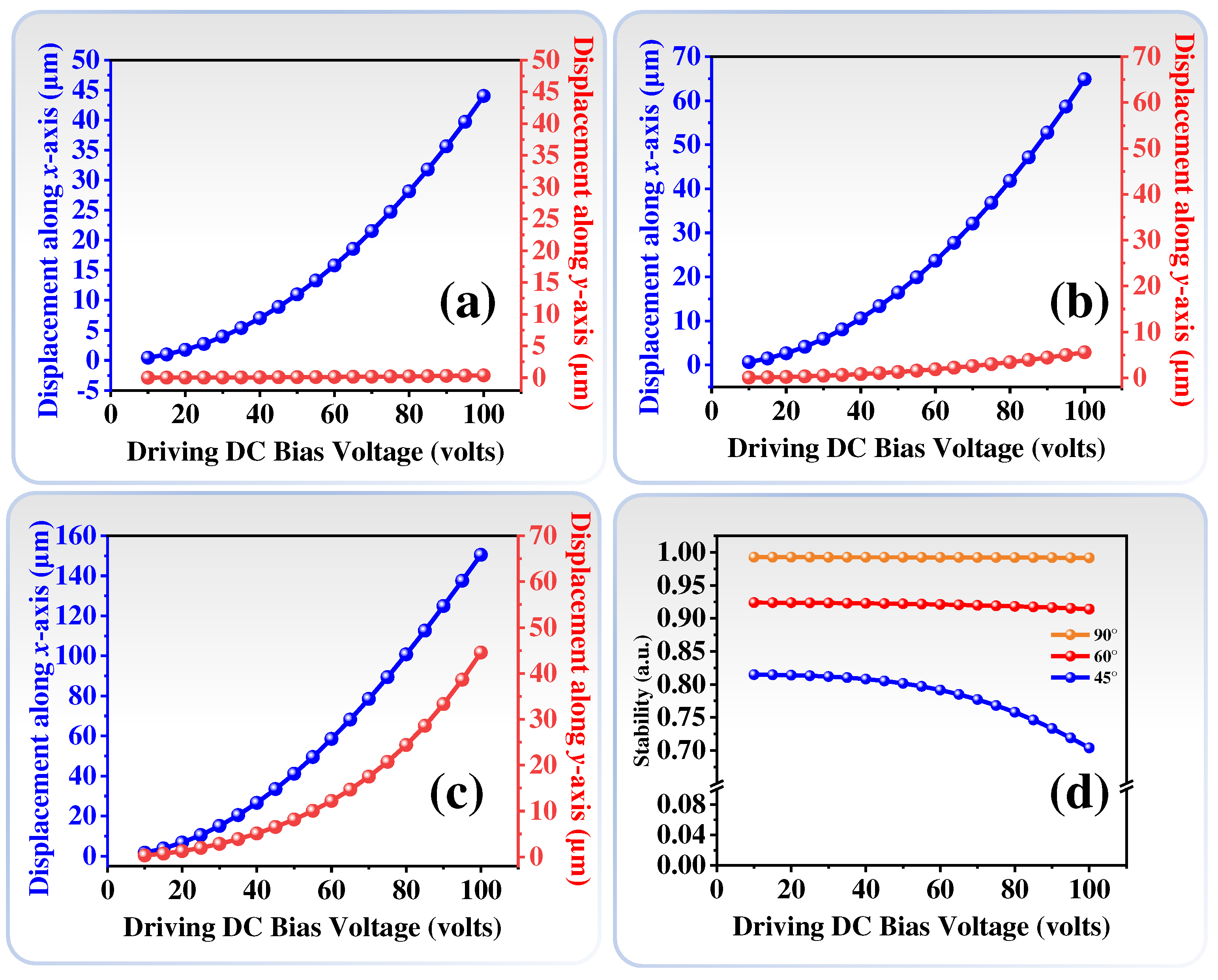
The relationships of displacements and different driving DC bias voltages of ECA with trapezoid combs under the conditions of
θ = 90°, 60°, and 45° are summarized in
Figure 5(a-c), respectively. In
Figure 5(a), when
θ = 90°, the trends of displacements and driving DC bias voltages in the
x-axis direction exhibits a quadratic relationship. At a DC bias voltage of 100 volts, the displacement in the
x-axis direction is 44 μm, and the displacement in the
y-axis direction is only 0.36 μm. This demonstrates that the ECA with trapezoid combs and
θ = 90° possesses high stability and large displacement. In
Figure 5(b), when
θ = 60°, although the displacement in the
x-axis direction increases to 64.89 μm at a DC bias voltage of 100 volts, however, the displacement in the
y-axis direction also increases to 5.58 μm. It indicates that the ECA starts to be unstable by reducing the crab-leg flexure beams angle. When
θ = 45°, the displacement in the
x-axis direction has a significant increase, which reaches up to 150.47 μm at a DC bias voltage of 100 volts as shown in
Figure 5(c). However, the displacement in the
y-axis direction also increases to 44.552 μm. It indicates that the ECA is highly unstable. The relationships of stabilities and different driving DC bias voltages under the conditions of different crab-leg flexure beams angles are summarized in
Figure 5(d). The stability of ECA is defined as the difference between the ratio of the displacement in the
y-axis direction to the displacement in the
x-axis direction and unity. When
θ = 90°, the stability of the ECA exceeds 0.99 from the driving DC bias voltage of 20 volts to 100 volts. While
θ = 60°, the stability of the ECA decreases from 0.92 at driving DC bias voltage of 20 volts to 0.91 at driving DC bias voltage of 100 volts. It maintains above 0.90. When
θ = 45°, the stability of the ECA drops to 0.81 at driving DC bias voltage of 20 volts and further diminishes to 0.7 at driving DC bias voltage of 100 volts. Under a DC bias voltage of 100 volts, the stability of the ECA with
θ = 90° is 1.1-fold higher than that with
θ = 60° and 1.4-fold higher than that
θ = 45°, respectively. These results indicate that the optimized design of ECA with trapezoid combs and crab-leg flexure beams of 90° exhibits larger displacement and stability.
