Submitted:
21 December 2023
Posted:
22 December 2023
You are already at the latest version
Abstract
Keywords:
1. Introduction
2. Topologies of Permanent Magnet Rotors
2.1. Inner and Outer Rotor Configurations
2.2. Sourface-Mounted Permanent Magnet Rotors

2.3. Interior Permanent Magnet Rotors
2.4. Comparative Analysis of PMSMs Configurations
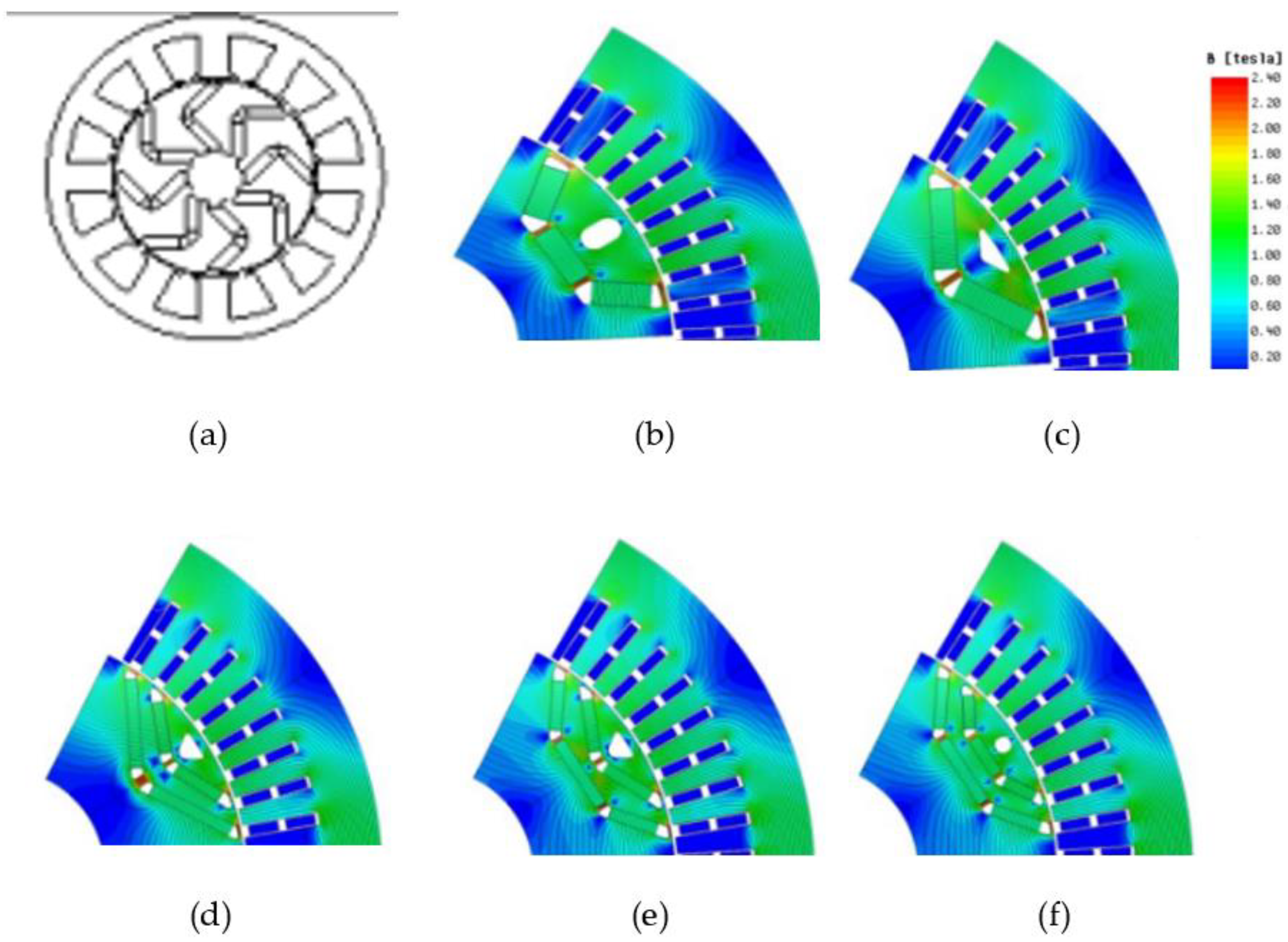
3. Thermal Analysis and Permanent Magnet Demagnetization Effects
3.1. Magnetic Material Categories
- Diamagnetic materials have no pure magnetic moment, at the atomic or molecular level. When diamagnetic materials are subjected to the action of an external field, atomic currents are produced which cause total magnetization which opposes the external field that caused it. Bismuth (Bi) is an example of the diamagnetic material.
- Paramagnetic materials have a pure magnetic moment at the atomic level, but the coupling between neighboring magnetic moments is weak. These magnetic moments tend to align with an external magnetic field, but the magnitude of the alignment decreases at higher temperatures due to random thermal agitation effects. Materially the adjacent magnetic moments are unequal resulting in a net magnetic moment.
- Ferromagnetic materials have pure magnetic moment at the atomic level, but unlike paramagnetic materials there is strong coupling between neighboring magnetic moments. This strong coupling causes a spontaneous alignment of magnetic moments at the macroscopic level, in regions called magnetic fields. The magnetic fields are further aligned under the influence of an external field. They are classified into soft and hard ferromagnetic materials depending on the value of the coherent field ().
- Finally, the antiferromagnetic materials and ferromagnetic materials have neighboring atomic moments oriented antiparallel. In antiferromagnetic materials the adjacent magnetic moments are equal, so that there is no net magnetic moment. In ferromagnetic materials the neighboring magnetic moments are unequal so that there is a net magnetic moment.
3.2. Demagnetization Field

3.3. Hard Magnetic Material Characteristics
3.4. Thermal Modeling of Permanent Magnets
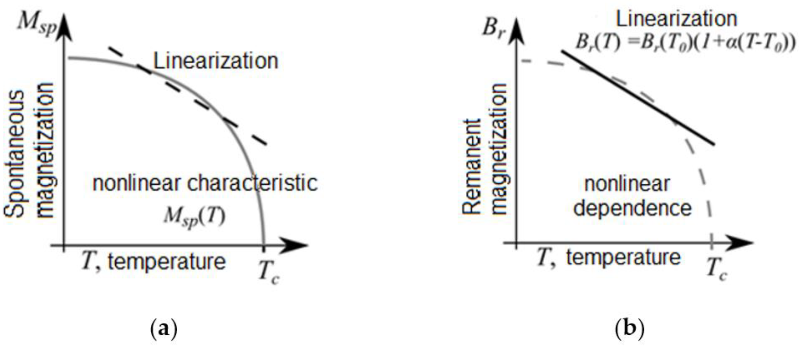
- E indicates the units of measurement of the exponential term (1 T or 1 kGauss)
- denotes the relative magnetic permeability
- is given by the manufacturer and indicates the residual magnetization.
- indicates the acidity of the knee; indicative value is -4-10-5m/A for neodymium NdFeB magnets of classical grade (regular grade magnet).
- K2 is calculated from the equation:
3.5. Demagnetization Modeling of Permanent Magnets
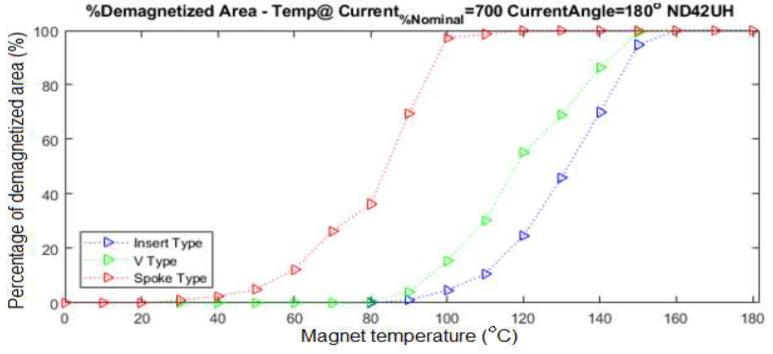
3.6. Demagnetization Consideration Methodology
4. Combined Permanent Magnet and Lamination Loss Modelling
4.1. Experimental Setup
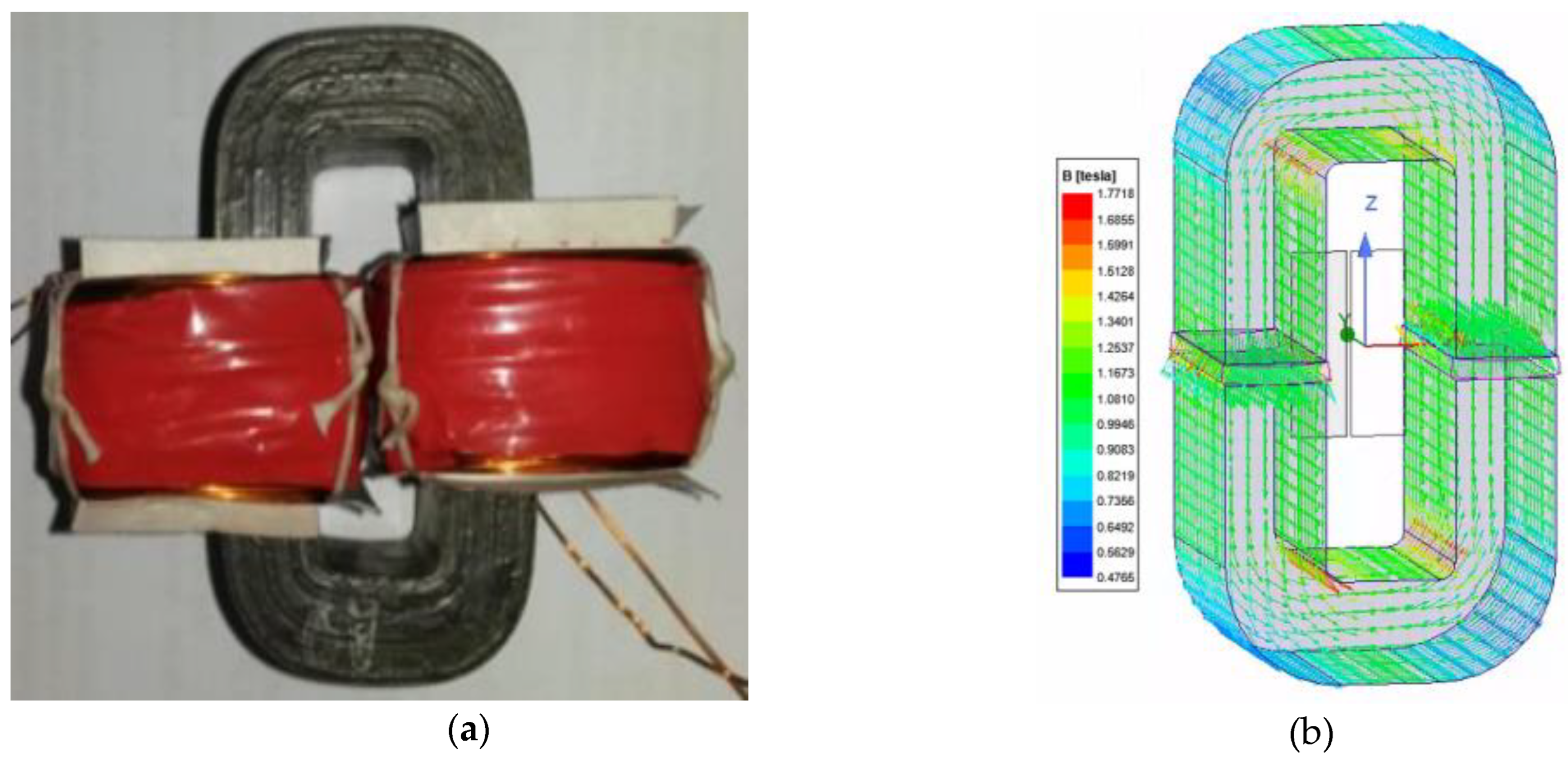
4.2. Core Loss in C-Core Magnetic Circuit
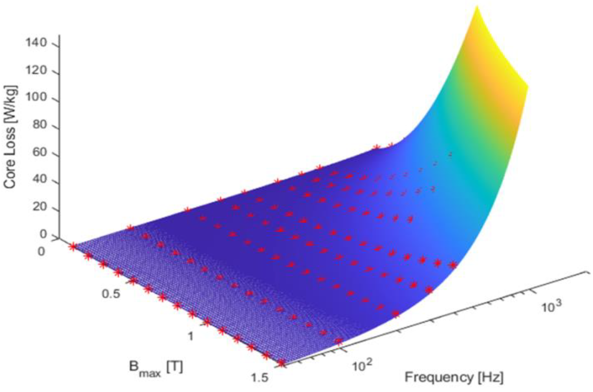
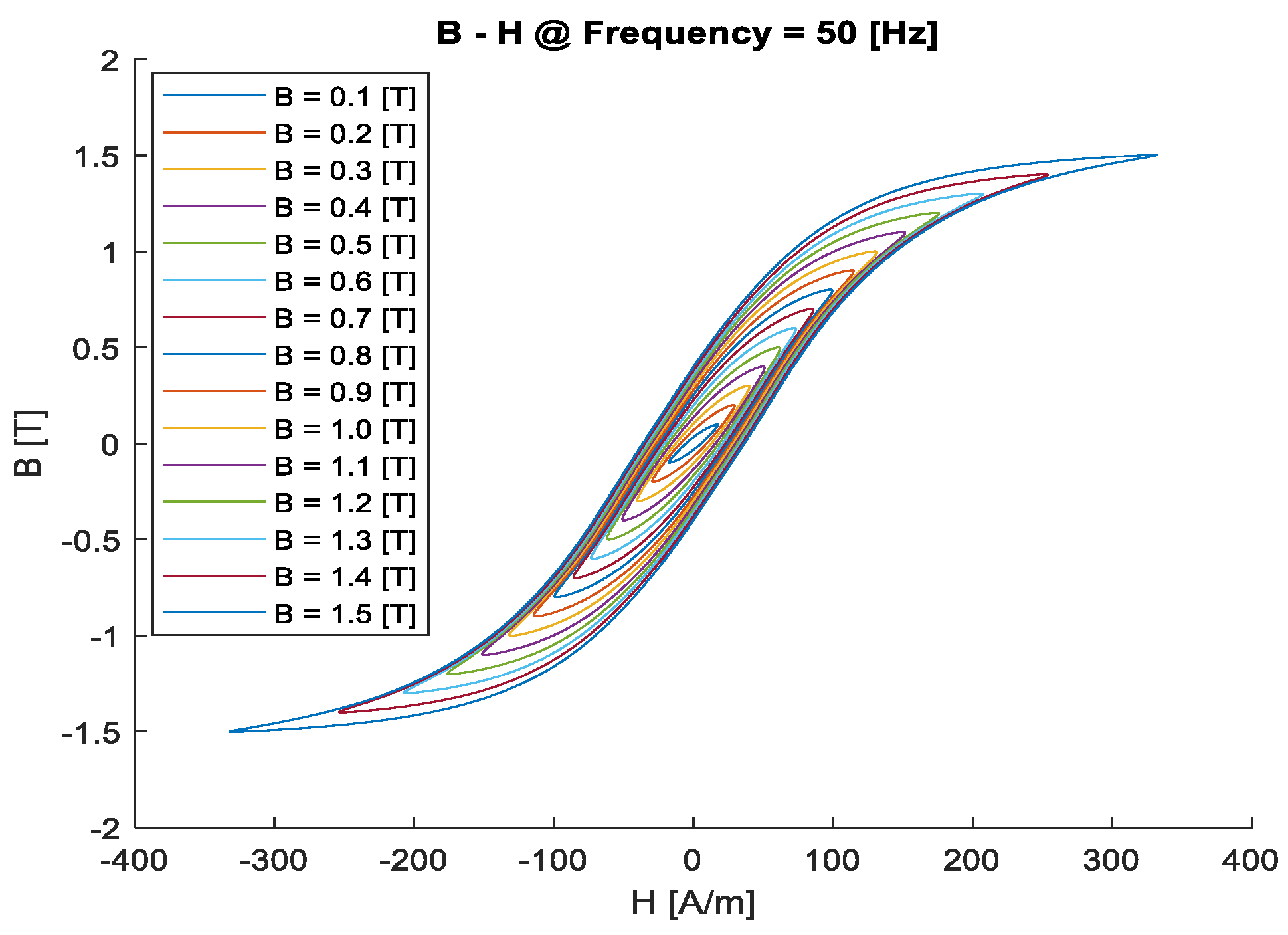
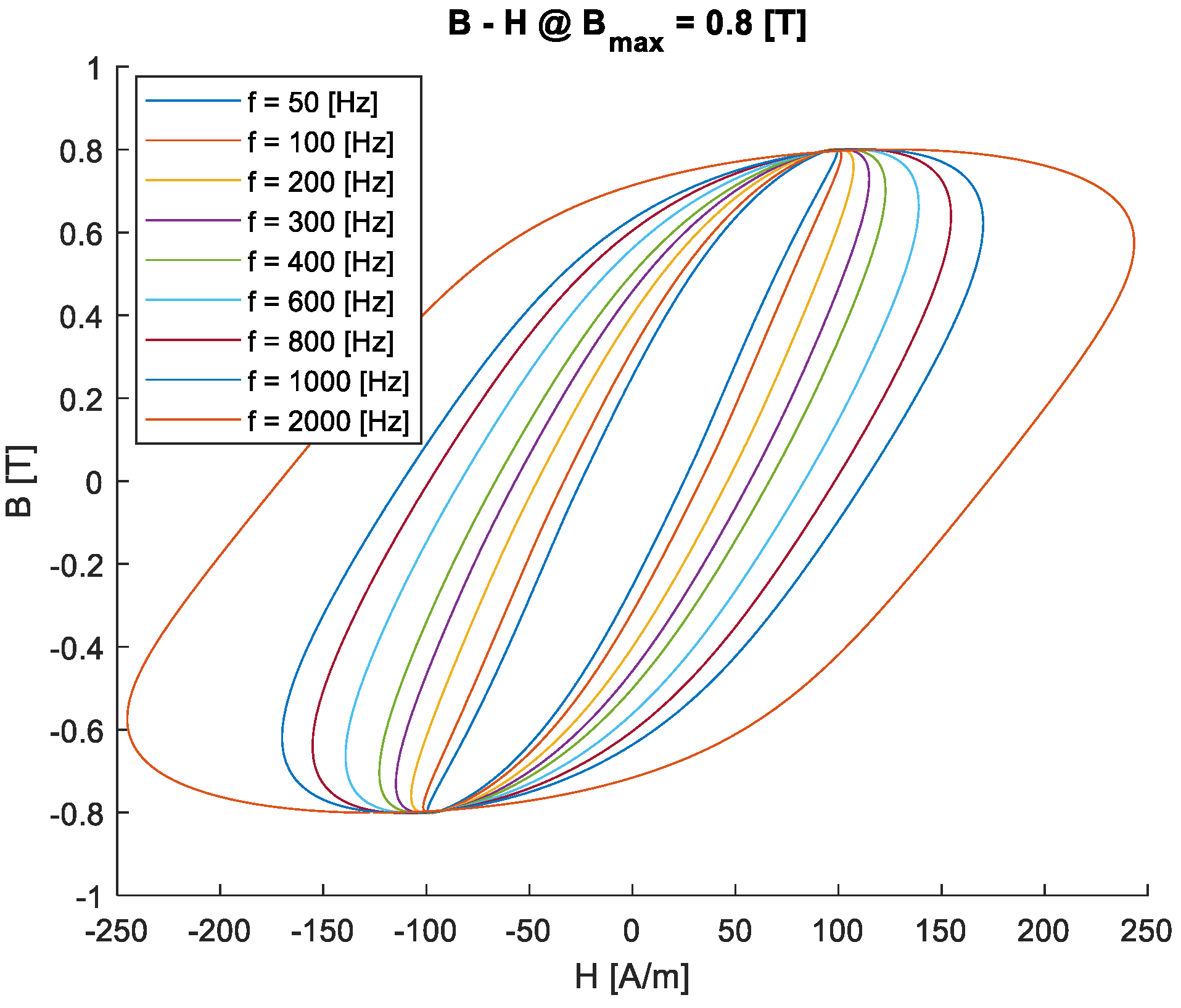
- =1.05·10-2[7.W/(kgT2Hz)] represents the hysteresis loss coefficient.
- KC = 7.91·10-5[7.W/(kgT2Hz2)] represents the eddy current loss coefficient.
- = 3.16·104[7.W/(kgT1.5Hz1.5)] represents the excess loss coefficient.
4.3. Magnet Losses
4.9. Experimental Validation in a LinearMotor Prototype
| Results | Parameters | Value |
|---|---|---|
| Maxwell Simulation | Fundamental amplitude (mV) | 962 |
| THD (%) | 25.8 | |
| Laboratory Measurements | Fundamental amplitude (mV) | 984.3 |
| THD (%) | 19,62 | |
| Error | Fundamental amplitude (mV) | 2.2% |
| THD (%) | 23.9% |
5. Mixed Numerical Techniques for the Simulation of Permanent Magnet Machines
6. Mechanical Analysis of Electrical Machines
6.1. Mechanical Deformation Effects
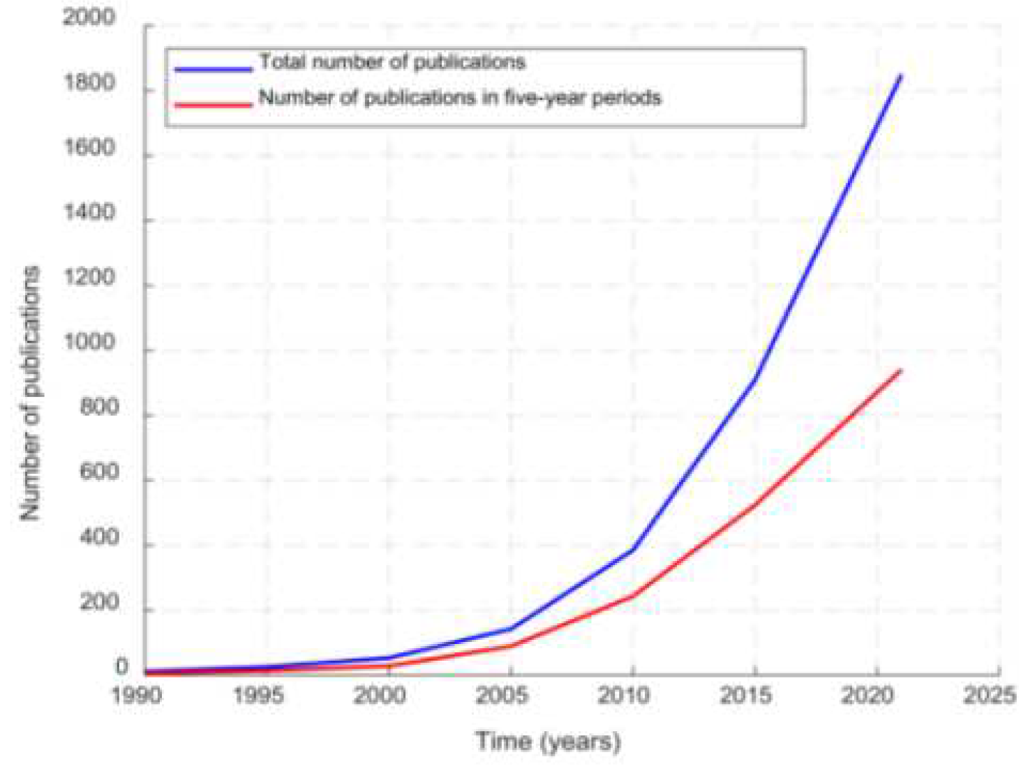
6.2. Mechanical Analysis in Electrical Machines
6.2.1. Vernier Machines
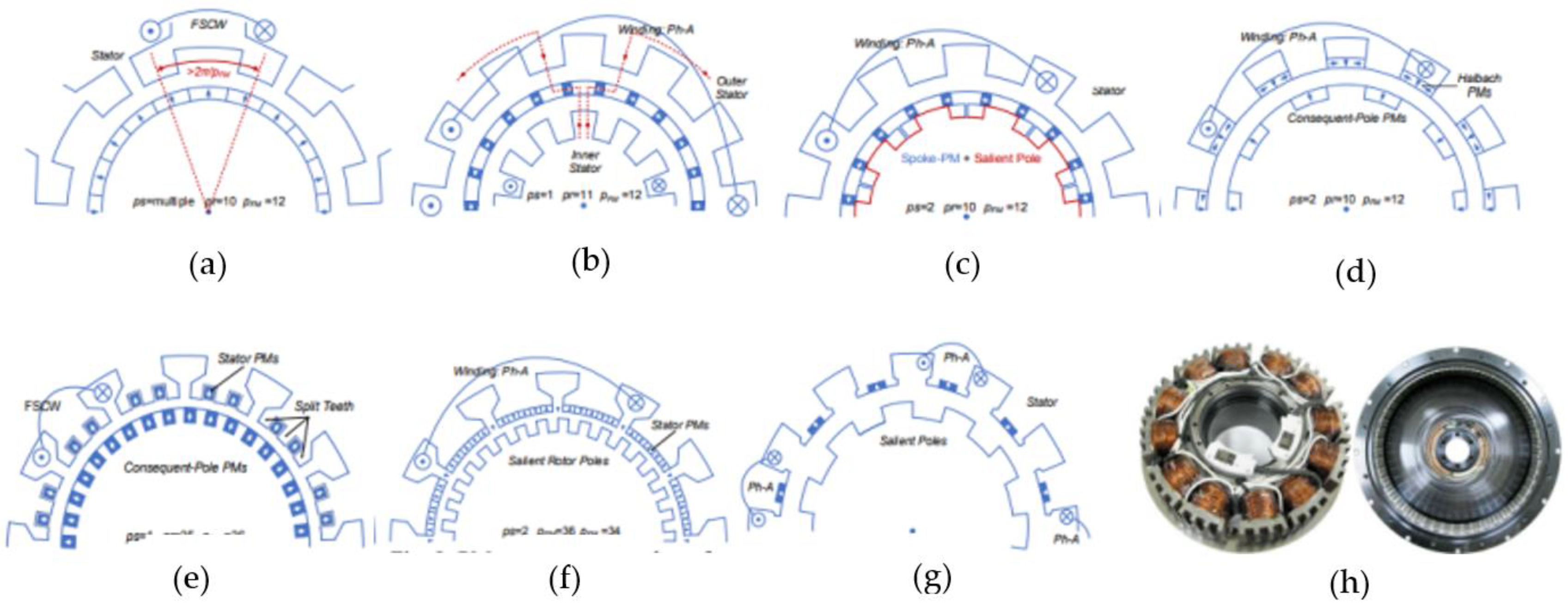
6.2.2. Flux-switching Electrical Motors

6.2.3. Flux Reversal Electrical Motors
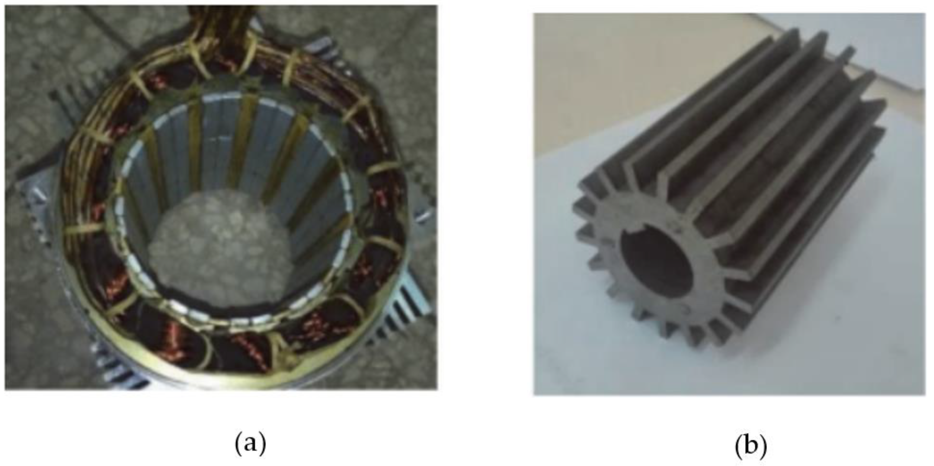
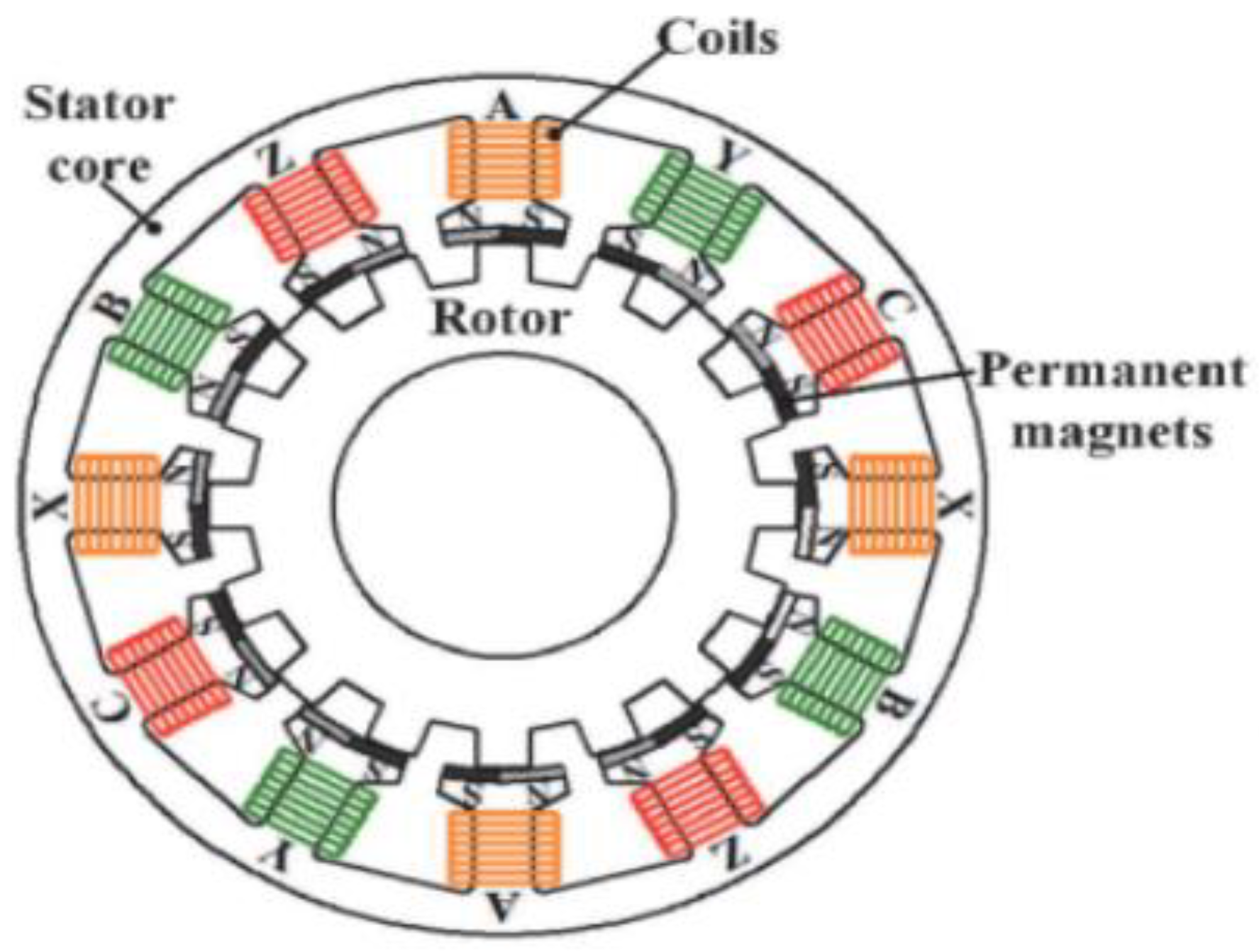
6.2.4. Special Electrical Motors
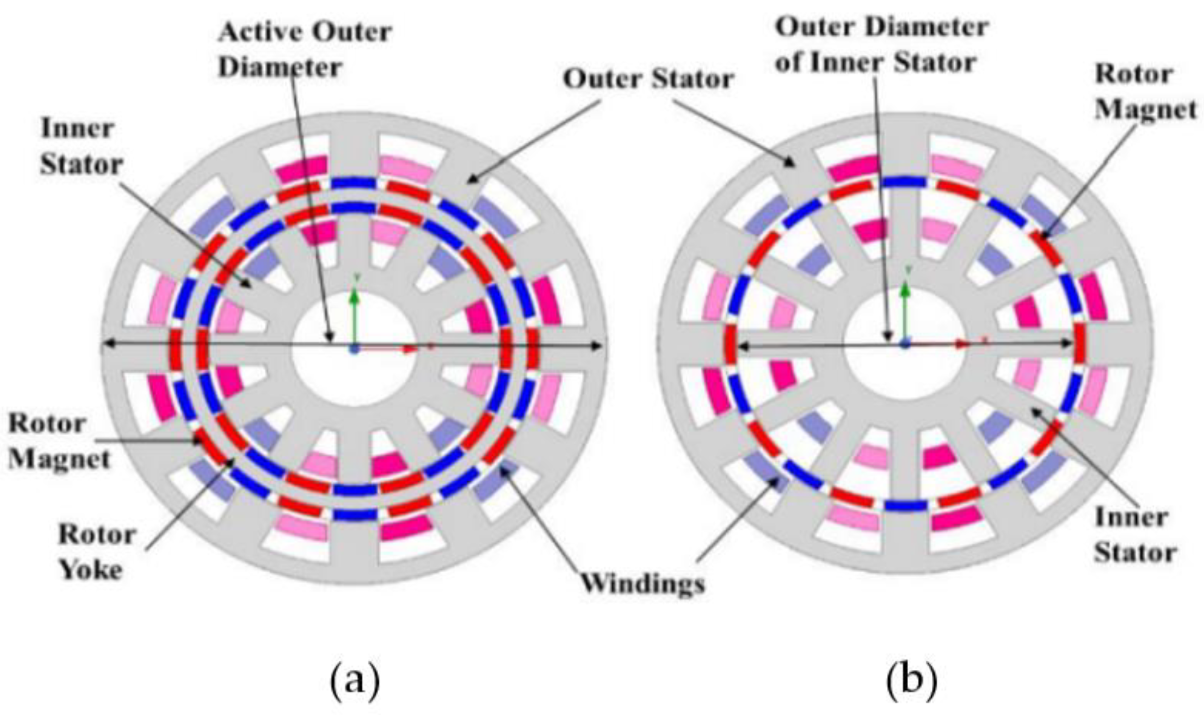
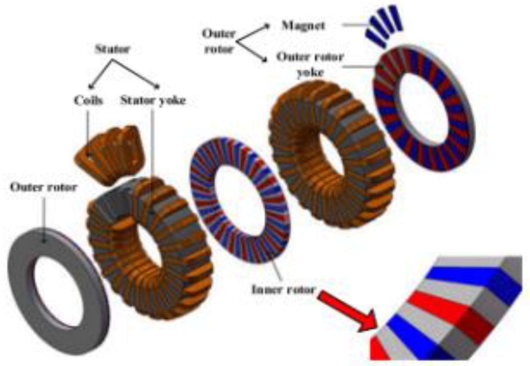
6.3. Case study using Basic 2-D Mechanical Analysis
6.3.1. Formulation of the 2D model for Mechanical Analysis
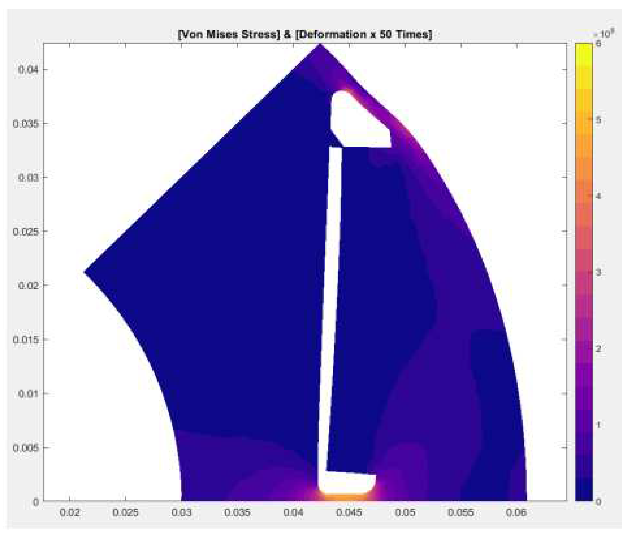
6.3.2. Formulation of the 2D Model for Electromagnetic Analysis
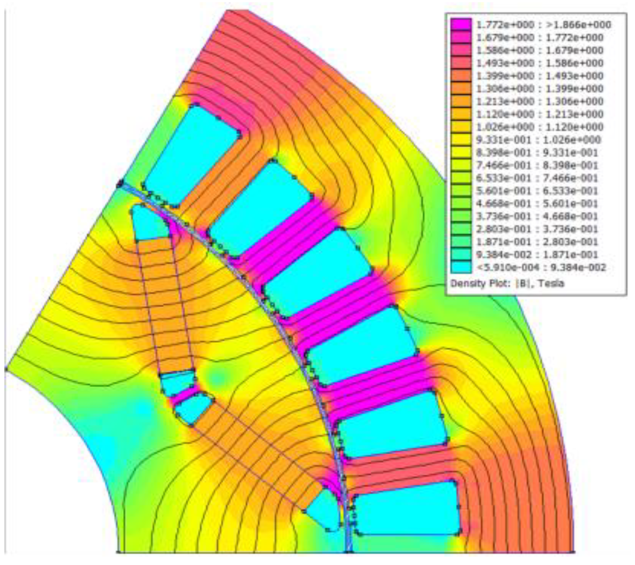
6.3.3. Optimization of Rotor Mass and Leakage Flux
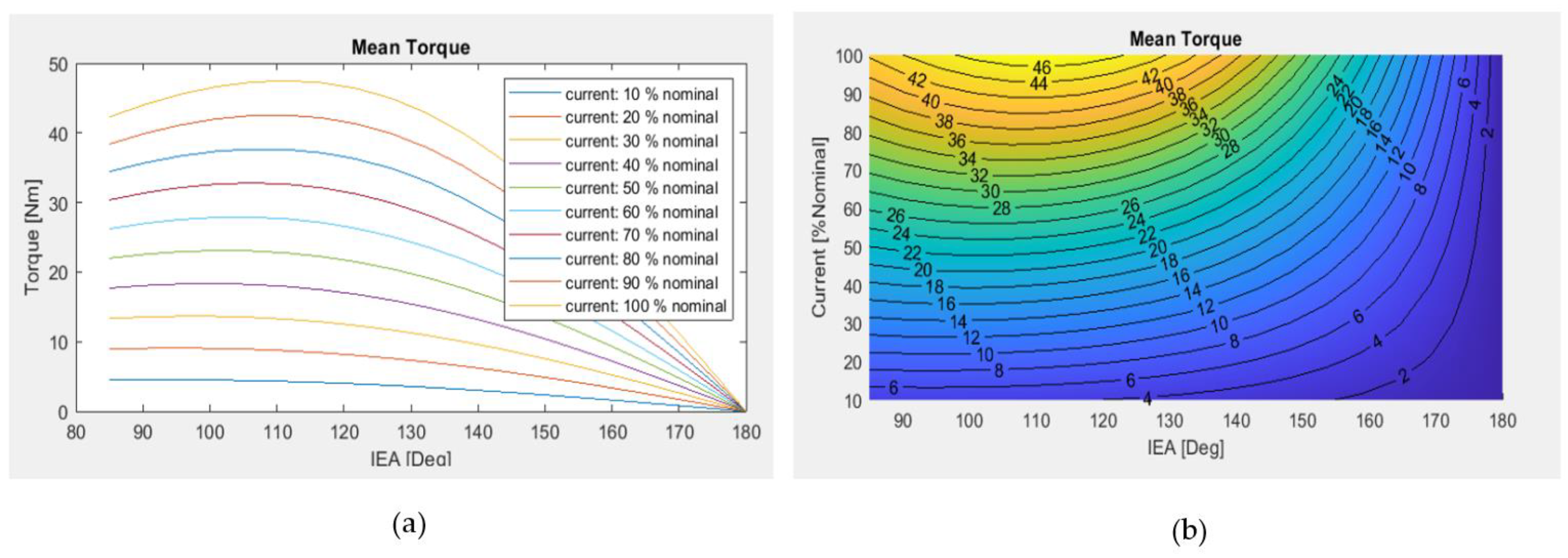
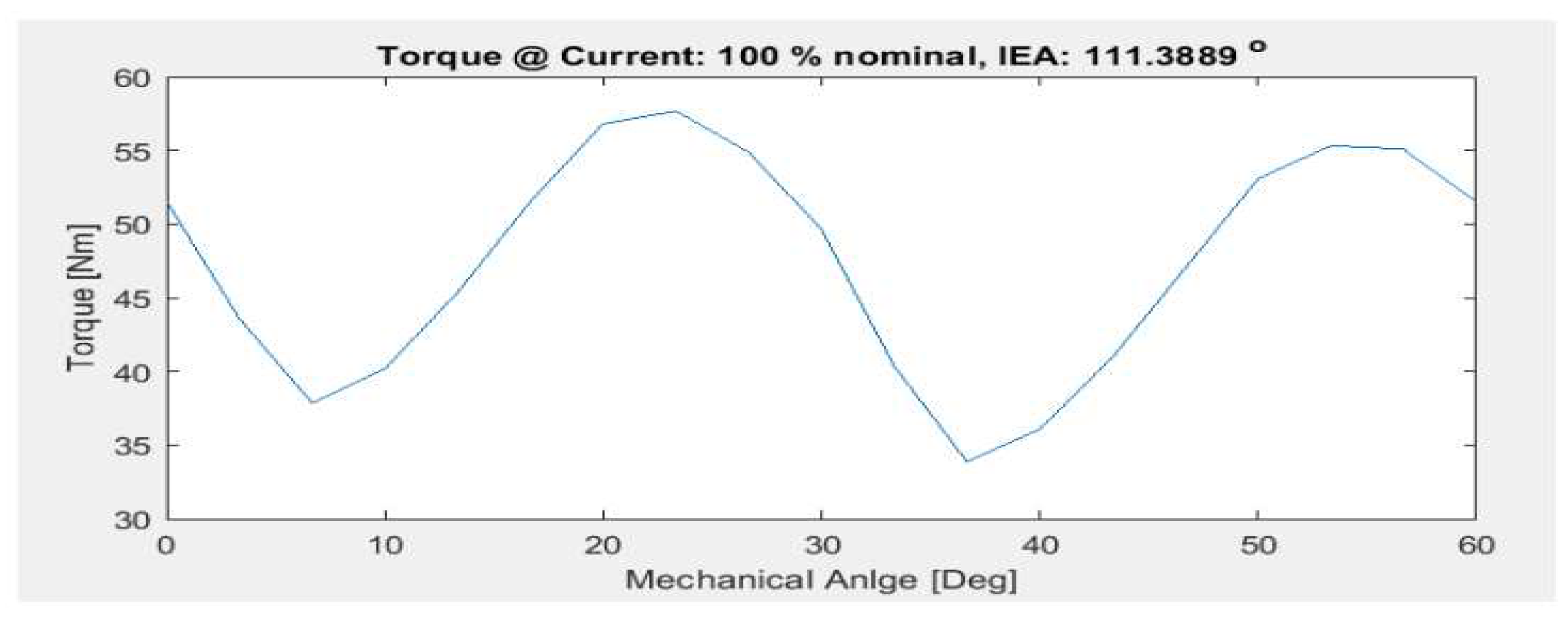
6.3.4. Spatial Harmonics in the Air Gap
7. Conclusions
Author Contributions
Funding
Data Availability Statement
Conflicts of Interest
References
- Chau, T.K.; Chan, C.C.; Liu, C. Overview of Permanent-Magnet Brushless Drives for Electric and Hybrid Electric Vehicles. IEEE Trans. Ind. Elect. 2008, 55, 2246–2257. [Google Scholar] [CrossRef]
- Yang, Y.; He, Q.; Fu, C.; Liao, S.; Tan, P. Efficiency improvement of permanent magnet synchronous motor for electric vehicles. Ener. 2020, 213, 1–11. [Google Scholar] [CrossRef]
- Lee, C.H.T.; Hua, W.; Long, T.; Jiang, C.; Iyer, L.V. A critical review of emerging technologies for electric and hybrid vehicles. IEEE Open J. Veh. Techn. 2021, 2, 471–485. [Google Scholar] [CrossRef]
- Li, C.; Chau, K.T.; Lee, C.H.T.; Song, Z. A critical review of advanced electric machines and control strategies for electric vehicles. IEEE Proc. 2021, 109, 1004–1008. [Google Scholar] [CrossRef]
- Wang, Z.; Ching, T.W.; Huang, S.; Wang, H.; Xu, T. Challenges faced by electric vehicle motors and their solutions. IEEE Acc. 2020, 9, 5228–5249. [Google Scholar] [CrossRef]
- Yu, Z.; Li, Y.; Jing, Y.; Wang, J. Cooling system of outer rotor SPMSM for a two-seater all-electric aircraft based on heat pipe technology. IEEE Trans. Tran. Elect., 2022, 8, 1656–1664. [Google Scholar] [CrossRef]
- Beniakar, M.E.; Kakosimos, P.E.; Krasopoulos, C.T.; Sarigiannidis, A.G.; Kladas, A.G. Comparison of in-wheel permanent magnet motors for electric traction. In Proceedings of the 2014 International Conference on Electrical Machines (ICEM), Berlin, Germany, September 2-5 2014; pp. 2472–2478. [Google Scholar]
- Fang, H.; Qu, R.; Li, J.; Zheng, P.; Fan, X. Rotor Design for High-Speed High-Power Permanent-Magnet Synchronous Motor. IEEE Trans. Ind. Appl. 2017, 53, 3411–3419. [Google Scholar] [CrossRef]
- Bekka, N.; El, H. Zaim, M.El.H.; Bernard, N.; Trichet, D. A novel methodology for optimal design of fractional slot with concentrated windings. IEEE Trans. En. Con. 2016, 31, 1153–1160. [Google Scholar] [CrossRef]
- Wang, K.; Zhu, Z. Q.; Ombach, G. , Torque enhancement of surface-mounted permanent magnet machine using third-order harmonic. IEEE Trans. Magn. 2014, 50, 2014. [Google Scholar] [CrossRef]
- Mirahki, H.; Moallem, M.; Ebrahimi, M.; Fahimi, B. Asymmetrical magnet shape optimization based on S-C mapping for torque profile mitigation in unidirectional application of SPMS machine. IEEE Trans. Tran. Elect. 2019, 5, 630–637. [Google Scholar] [CrossRef]
- Du, Z.S.; Lipo, T.A. High torque density and low torque ripple shaped-magnet machines using sinusoidal plus third harmonic shaped magnets. IEEE Trans. Ind. Appl.s 2019, 55, 2601–2610. [Google Scholar] [CrossRef]
- Park, H.J.; Lim, M.S.; Lee, C.S. Magnet shape design and verification for SPMSM of EPS system using cycloid curve. IEEE Acc. 2019, 7, 137207–137216. [Google Scholar] [CrossRef]
- Chabchoud, M.; Salah, I. B.; Krebs, G.; Neji, R.; Marchand, C. PMSM cogging torque reduction: comparison between different shapes of magnet. Ιn Proceedings of 2012 1st International Conference on Renewable Energies and Vehicular Technology, Nabeul, Tunisia, Mar. 26-28, 2012; pp. 206-211.
- Singh, S.; Pillay, P. Sinusoidal shaped surface permanent magnet motor using cold spray additive manufacturing. In Proceedings of the 2020 IEEE Energy Conversion Congress and Exposition (ECCE), Detroit, MI, USA, Oct. 11-15 2020; pp. 2089–2094. [Google Scholar]
- Lim, M.S.; Chai, S.H.; Yang, J.S.; Hong, J. P. Design and verification of 150-krpm PMSM based on experiment results of prototype. IEEE Trans. Ind. Ele., 2015, 62, 7827–7836. [Google Scholar] [CrossRef]
- Yoneda, M.; Shoji, M.; Kim, Y.; Dohmeki, H. Novel selection of the slot/pole ratio of the PMSM for auxiliary automobile. In Proceedings of the Conference Record of the 2006 IEEE Industry Applications Conference Forty-First IAS Annual Meeting, Tampa, FL, USA, 8–12 October 2006; pp. 8–13. [Google Scholar]
- He, C.; Wu, T. Analysis and design of surface permanent magnet synchronous motor and generator. CES Trans. Electr. Machines and Systems 2019, 3, 94–100. [Google Scholar]
- Chung, S.U.; Kim, J.W.; Chun, Y. D.; Woo, B. C; Hong, D.K. Fractional slot concentrated winding PMSM with consequent pole rotor for a low-speed direct drive: reduction pf rare earth permanent magnet. IEEE Trans. Energy Convers. 2015, 30, 103–109. [Google Scholar] [CrossRef]
- Sayed, E.; Yang, Y.; Bilgin, B.; Bakr, M.H.; Emadi, A.A. comprehensive review of flux barriers in interior permanent magnet synchronous machines. IEEE Acc. 2019, 7, 149168–149181. [Google Scholar] [CrossRef]
- Liu, G.; Zhai, F.; Chen, Q.; Xu, G. Torque pulsation reduction in fractional-slot concentrated-windings IPM motors by lowering sub-harmonics. IEEE Trans. Energy Convers., 2019, 34, 2084–2095. [Google Scholar] [CrossRef]
- Kong, Y.; Lin, M.; Jia, L. A novel high power density permanent-magnet synchronous machine with wide speed range. IEEE Trans. Magn. 2020, 56. [Google Scholar] [CrossRef]
- Li, J.; Xu, Y.; Zou, J.; Wang, Q.; Liang, W. Analysis and reduction of magnet loss by deepening magnets in interior permanent-magnet machines with a pole/slot ratio of 2/3. IEEE Trans. Magn. 2015, 51. [Google Scholar] [CrossRef]
- Sun, X.; Shi, Z.; Lei, G.; Guo, Y.; Zhu, J. Multi-objective design optimization of an IPMSM based on multilevel strategy. IEEE Trans. Ind. Electr. 2021, 68, 139–148. [Google Scholar] [CrossRef]
- Ma, Q.; Refaie, El A. ; Lequesne, B. Low-cost interior permanent magnet machine with multiple magnet types. IEEE Trans. Ind. Appl. 2020, 56, 1452–1463. [Google Scholar] [CrossRef]
- Miyamasu, M. ; K. Akatsu, K. An approach to generate high reluctance torque in an inset-type PMSM by square current excitation. In Proceedings of 2012 IEEE International Conference on Power and Energy (PECon), Kota, Kinabalu, Malaysia, December 2-5 2012; pp. 440–445. [Google Scholar]
- Gao, P.; Gu, Y.; Shah, H. S.; Abubakar, U.; Wang, X. , Calculation and analysis of flux leakage coefficient of interior permanent magnet synchronous motors with fractional slot concentrated windings. IEEE Trans. Appl. Super. 2019, 29. [Google Scholar] [CrossRef]
- Toulabi, M.S.; Salmon, J.; Knight, A.M. Concentrated winding IPM synchronous motor design for wide field weakening applications. IEEE Trans. Ind. Appl. 2017, 53, 1892–1900. [Google Scholar] [CrossRef]
- Toulabi, M.S.; Salmon, J.; Knight, A.M. Concentrated winding IPM synchronous motor design for wide field weakening applications. IEEE Trans. Ind. Appl. 2017, 53, 1892–1900. [Google Scholar] [CrossRef]
- Chai, F.; Li, Y.; Liang, P.; Pei, Y. Calculation of the maximum mechanical stress on the rotor of interior permanent-magnet synchronous motors. IEEE Trans. Ind. Electr. 2016, 63, 3420–3432. [Google Scholar] [CrossRef]
- Hong, S.G.; Park, II.H. Continuum-sensitivity-based optimization of interior permanent magnet synchronous motor with shape constraint for permanent magnet. IEEE Trans.Magn. 2020, 56. [Google Scholar] [CrossRef]
- Lim, H.K.; Song, B.K.; Kim, S.II.; Hong, J.P. A study on the relation between rotor rib and maximum power of IPMSM in flux weakening region. In Proceedings of the 2010 International Conference on Electrical Machines and Systems, Incheon, South Korea, 10–13 October 2010. [Google Scholar]
- Chen, Z.; Li, G. A V type permanent magnet motor simulation analysis and prototype test for electric vehicle. IEEE Acc. 2019, 7, 174839–46. [Google Scholar] [CrossRef]
- Lee, K.D.; Lee, H.W.; Lee, J.; Kim, W.H. Analysis of motor performance according to the inductance design of IPMSM. IEEE Trans.Magn., 2015, 51. [Google Scholar]
- Song, I.S.; Lee, C.H.; Kim, K.C. Comparison characteristics according to changing magnet pole-arc of double-layered V-shape IPMSM for large commercial EVs. In Proceedings of the 2021 24th International Conference on Electrical Machines and Systems (ICEMS), Gyeongju, Korea, Oct. 31 – Nov. 3 2021. [Google Scholar]
- Dong, J.; Gu, A.; Yang, M.; Zhang, D. A method for improving torque performances of IPMSM. In Proceedings of the 8th International Conference on Power Electronics Systems and Applications (PESA), Hong Kong, China, Dec. 7-10 2020. [Google Scholar]
- Ma, C.; Li, J.; Zhao, H.; Wang, J.; Yin, X.; Zuo, S.; Wu, X.; Lu, H. 3-D analytical model of armature reaction field of IPMSM with multi-segmented skewed poles and multi-layered flat wire winding considering current harmonics. IEEE Acc. 2020, 8, 151116–1511124. [Google Scholar] [CrossRef]
- Zuopeng, D.; Bing, Ζ.; Dejun, Υ. A design of fractional-slot concentrated winding IPM synchronous motor for electric vehicle. Ιn Proceedings of IECON 2017 – 43rd Annual Conference of the IEEE Industrial Electronics Society, Beijing, China, Oct. 29 – Nov. 1 2017.
- Park, S.H.; Chin, J.W.; Cha, K.S.; Ryu, J.Y.; Lim, M.S. Characteristic analysis of IPMSM for EV traction considering the effect of field and armature excitations on AC copper loss. In Proceedings of the 2021 IEEE Energy Conversion Congress and Exposition (ECCE). Vancouver, BC, Canada, 2021, 10-14 October 2021; pp. 4486–4491. [Google Scholar]
- Kim, Y.K.; Jeong, L.J.; Rhyu, S.H.; Jung, I.S. A study on permanent magnet synchronous motor for neighborhood electric vehicle. In Proceedings of the 2012 IEEE Vehicle Power and Propulsion Conference, Seoul, South Korea, 9-12 October 2012; pp. 1081–1085. [Google Scholar]
- Kim, M.J.; Lee, K.D.; Lee, J.J.; Han, G.H.; Jeong, T.C.; Kim, W.H.; Koo, D.H.; Lee, J. Torque density elevation in concentrated winding interior PM synchronous motor with minimized magnet volume. IEEE Trans. Magn. 2013, 49, 3334–3337. [Google Scholar] [CrossRef]
- Hao, J.; Suo, S.; Yang, Y.; Wang, Y.; Wang, W.; Chen, X. Optimization of torque ripples in an interior permanent magnet synchronous motor based on the orthogonal experimental method and MIGA and RBF neural networks. IEEE Acc. 2020, 8, 27202–27209. [Google Scholar] [CrossRef]
- Galioto, S.J.; Reddy, P.B.; El-Refaie, A.M.; Alexander, J.P. Effect of magnet types on performance of high-speed spoke interior-permanent-magnet machines designed for traction applications. IEEE Trans. Ind. Appl. 2015, 51, 2148–2160. [Google Scholar] [CrossRef]
- Fatemi, A.; Ionel, D.M.; Popescu, M.; Chong, Y.C.; Demerdash, N.A.O. Design optimization of a high torque-density spoke-type PM motor for a formula E race drive cycle. IEEE Trans. Ind. Appl. 2018, 54, 4343–4354. [Google Scholar] [CrossRef]
- Kim, K.-C. A novel method for minimization of cogging torque and torque ripple for interior permanent magnet synchronous motor. IEEE Trans. Magn. 2014, 50. [Google Scholar] [CrossRef]
- Hwang, K.Y.; Jo, J.H.; Kwon, B.I. A study on optimal pole design of spoke-type IPMSM with concentrated winding for reducing the torque ripple by experiment design method. IEEE Trans. Magn. 2009, 45, 4712–4715. [Google Scholar] [CrossRef]
- Wang, J.; Geng, W.; Li, Q.; Li, L.; Guo, J. A novel spoke-type IPM rotor with hybrid radial and axial flux concentration for reduction of interpolar leakage flux. IEEE Trans. Magn. 2022, 58. [Google Scholar] [CrossRef]
- Hemmati, R.; Vahid, S.; EL-Refaie, A. A novel design for a high specific power interior permanent magnet machine for aerospace applications. In Proceedings of the 2020 IEEE Energy Conversion Congress and Exposition (ECCE), Detroit, MI, USA, 11-15 October 2020; pp. 1735–1742. [Google Scholar]
- Cui, W.; Wang, D.; Ren, L.; Zhang, Y. A new optimized IPMSM for EVs with reduced magnet loss for over-modulation operation. IEEE Trans. Magn. 2023, 59. [Google Scholar] [CrossRef]
- Kim, S.II.; Kim, Y.K.; Lee, G.H.; Hong, J.P. A novel rotor configuration and experimental verification of interior PM synchronous motor for high-speed applications. IEEE Trans. Magn. 2012, 48, 843–846. [Google Scholar] [CrossRef]
- Choi, G.; Bramerdorfer, G. Comprehensive design and analysis of an interior permanent magnet synchronous machine for light-duty passenger EVs. IEEE Acc. 2021, 10, 819–831. [Google Scholar] [CrossRef]
- Jung, Y.H.; Park, M.R.; Kim, K.-O.; Chin, J.W.; Hong, J.P.; Lim, M.S. Design of high-speed multilayer IPMSM using ferrite PM for EV traction considering mechanical and electrical characteristics. IEEE Trans. Ind. Appl. 2021, 57, 327–339. [Google Scholar] [CrossRef]
- Cao, Z.; Liu, J. Cogging torque reduction for outer rotor interior permanent magnet synchronous motor. In Proceedings of the IECON 2020 46th Annual Conference of the IEEE Industrial Electronics Society, Singapore, Oct. 18-21 2020; pp. 2689–2693. [Google Scholar]
- Yu, D.; Huang, X.; Zhang, X.; Zhang, J.; Lu, Q.; Fang, Y. Optimal design of outer rotor interior permanent magnet synchronous machine with hybrid permanent magnet. IEEE Trans. Appl. Super. 2019, 29. [Google Scholar] [CrossRef]
- Nakata, T.; Sanada, M.; Morimoto, S.; Inoue, Y. Automatic design of IPMSMs using a genetic algorithm combined with the coarse-mesh FEM for enlarging the high-efficiency operation area. IEEE Trans. Ind. Electr. 2017, 64, 9721–9728. [Google Scholar] [CrossRef]
- Lee, Y.G.; Bang, T.K.; Woo, J.H.; Jo, S.T.; Choi, J.Y. Comparative study of mechanical and electromagnetic aspects of interior permanent magnet synchronous motor according to the rotor shapes. In Proceedings of the 2021 24th International Conference on Electrical Machines and Systems (ICEMS), Gyeongju, Korea, Oct. 31 – Nov. 3 2021; pp. 1279–1283. [Google Scholar]
- Yoshida, Y.; Yanagisawa, T.; Tajima, K. Consideration of asymmetrical magnetic pole IPMSM using bonded rare-earth magnet. In Proceedings of the 2020 23rd International Conference on Electrical Machines and Systems (ICEMS), Hamamatsu, Japan, Nov. 24-27 2020; pp. 720–723. [Google Scholar]
- Asef, P. ; Denai,M. ; Marques, B.R.; Paulides J.J.H.; Lapthorn, A. Commutation angle maps evaluation for magnet arrangements of interior permanent magnet synchronous machines in electric vehicles. In Proceedings of 2021 International Conference on Smart Energy Systems and Technologies (SEST), Vaasa, Finland, Sept. 6-8 2021. [Google Scholar]
- Guo, Y.; Liu, L.; Ba, X.; Lu, H.; Lei, G.; Yin, W.; Zhu, J. Designing High-Power-Density Electric Motors for Electric Vehicles with Advanced Magnetic Materials. World Elec. Veh. J. 2023, 14(4), 1–21. [Google Scholar]
- Pechlivanidou, M.S.C; Kladas, A.G. Tree-Dimensional- Printed Magnetic Iron Material Modelling for High Speed Actuators. IEEE Trans. Magn., 2023, 59. [Google Scholar] [CrossRef]
- Yu, G.; Huang, J.; Xiao, J.; Xu, Y.; Zou, J. Effect of High-Pressure Environment on Deep-Sea Permanent Magnet Synchronous Motors With Fe-Co-V Alloy. IEEE Trans. Magn. 2023, 59. [Google Scholar] [CrossRef]
- Manolas, I.; Kladas, A.; Svechkarenko, D.; Chin, R. Magnetization Regulation in Variable Flux PM-Assisted Synchronous Reluctance Machines. In Proceedings of the 2018 XIII International Conference on Electrical Machines (ICEM), Alexandroupoli, Greece, 03-06 September 2018; pp. 2224–2228. [Google Scholar]
- Tsunata, R.; Takemoto, M.; Ogasawara, S.; Orikawa, K. A Proposal of a Delta-Type Salient Pole Variable Flux Memory Motor Having Large Flux Barrier for Traction Applications. In Proceedings of the 2019 IEEE Energy Conversion Congress and Exposition (ECCE), Baltimore, MD, USA, 29 Sept.- 03 October 2019; pp. 6054–6061. [Google Scholar]
- Nair, S.S.; Patel, V.I.; Wang, J. Post-Demagnetization Performance Assessment for Interior Permanent Magnet AC Machines. IEEE Trans. Magn. 2016, 52. [Google Scholar] [CrossRef]
- Jeong, C.-L.; Hur, J. Optimization Design of PMSM with Hybrid-Type Permanent Magnet Considering Irreversible Demagnetization. IEEE Trans. Magn. 2017, 53. [Google Scholar] [CrossRef]
- Faiz, J.; Mazaheri-Tehrani, E. Demagnetization Modeling and Fault Diagnosing Techniques in Permanent Magnet Machines Under Stationary and Nonstationary Conditions: An Overview. IEEE Trans. Ind. Appl., 2017, 53, 2772–2785. [Google Scholar] [CrossRef]
- De Bisschop, J.; Sergeant, P.; Hemeida, A.; Vansompel, H.; Dupré, L. Analytical Model for Combined Study of Magnet Demagnetization and Eccentricity Defects in Axial Flux Permanent Magnet Synchronous Machines. IEEE Trans. Magn. 2017, 53. [Google Scholar] [CrossRef]
- Reigosa, D.; Fernández, D.; Martínez, M.; Park, Y.; Lee, S.B.; Briz, F. Permanent Magnet Synchronous Machine Non-Uniform Demagnetization Detection Using Zero-Sequence Magnetic Field Density. IEEE Trans. Ind. Appl. 2019, 55, 3823–3833. [Google Scholar] [CrossRef]
- Mörée, G.; Sjölund, J.; Leijon, M. A Review of Permanent Magnet Models Used for Designing Electrical Machines. IEEE Trans. Magn. 2022, 58, 1–19. [Google Scholar] [CrossRef]
- Hamidizadeh, S.; Alatawneh, N.; Chromik, R.R.; Lowther, D.A. Comparison of different demagnetization models of permanent magnet in machines for electric vehicle application. IEEE Trans. Magn. 2016, 52, 1–4. [Google Scholar] [CrossRef]
- Moosavi, S.S; Djerdir, A.; Amirat, Y.A.; Khaburi,D. A. Demagnetization fault diagnosis in permanent magnet synchronous motors: A review of the state-of-the-art. J. Magn. Magn. Mater. 2015, 391, 203–212. [Google Scholar] [CrossRef]
- Uršiˇc, L.; Nemec, M. Permanent magnet synchronous machine demagnetisation prevention and torque estimation control considering rotor temperature. IET Power Electron. 2019, 12, 2161–2169. [Google Scholar] [CrossRef]
- Leuning, N.; Elfgen, S.; Groschup, B.; Bavendiek, G.; Steentjes, S.; Hameyer, K. Advanced soft- and hard-magnetic material models for the numerical simulation of electrical machines. IEEE Trans. Magn. 2018, 54, 1–8. [Google Scholar] [CrossRef]
- Ruoho, S.; Dlala, E.; Arkkio, A. Comparison of Demagnetization Models for Finite-Element Analysis of Permanent-Magnet Synchronous Motor. IEEE Trans. Magn. 2007, 43, 3964–3968. [Google Scholar] [CrossRef]
- Choi, G. Analysis and Experimental Verification of the Demagnetization Vulnerability in Various PM Synchronous Machine Configurations for an EV Application. Energ. 2021, 14, 1–16. [Google Scholar] [CrossRef]
- De Bisschop, J.; Sergeant, P.; Hemeida, A.; Vansompel, H.; Dupre, L. Analytical Model for Combined Study of Magnet Demagnetization and Eccentricity Defects in Axial Flux Permanent Magnet Synchronous Machines. IEEE Trans. Magn. 2017, 53, 8107712. [Google Scholar] [CrossRef]
- Reigosa, D.; Fernandez, D.; Martinez, M.; Park, Y.; Lee, S.B.; Briz, F. Permanent Magnet Synchronous Machine Non-Uniform Demagnetization Detection Using Zero-Sequence Magnetic Field Density. IEEE Trans. Ind. Appl. 2017, 55, 3823–3833. [Google Scholar] [CrossRef]
- Lee, S.T. Demagnetization study of an interior permanent magnet synchronous machine considering transient peak 3 phase short circuit current. In Proceedings of the 2017 Annual Conference of the IEEE Energy Conversion Congress and Exposition (ECCE), Cincinnati, USA, 01-05 October 2017; pp. 4694–4698. [Google Scholar]
- Krichen, M.; Elbouchikhi, E.; Benhaji, N.; Chaieb, M.; Benbouzid, M.; Neji, R. Motor Current Signature Analysis-Based Permanent Magnet Synchronous Motor Demagnetization Characterization and Detection. Mach. 2020, 8, 1–29. [Google Scholar] [CrossRef]
- Dobzhanskyi, O.; Grebenikov, V.; Gouws, R.; Gamaliia, R.; Hossain, E. Comparative Thermal and Demagnetization Analysis of the PM Machines with Neodymium and Ferrite Magnets. Ener. 2022, 15, 1–15. [Google Scholar] [CrossRef]
- Wang, J.; Wang, W.; Atallah, K.; Howe, D. Demagnetization Assessment for Three-Phase Tubular Brushless Permanent-Magnet Machines. IEEE Trans. Magn. 2008, 44, 2195–2203. [Google Scholar] [CrossRef]
- Sjokvist, S.; Eriksson, S. Investigation of Permanent Magnet Demagnetization in Synchronous Machines during Multiple Short-Circuit Fault Conditions. Ener. 2017, 10, 1–12. [Google Scholar] [CrossRef]
- Baranski, M.; Szelag, W.; Lyskawinski, W. Analysis of the Partial Demagnetization Process of Magnets in a Line Start Permanent Magnet Synchronous Motor. Ener. 2020, 13, 1–20. [Google Scholar] [CrossRef]
- Zhou, P.; Lin, D.; Xiao, Y.; Lambert, N.; Rahman, M.A. Temperature-Dependent Demagnetization Model of Permanent Magnets for Finite Element Analysis. IEEE Trans. Magn. 2012, 48, 1031–1034. [Google Scholar] [CrossRef]
- Li, Z.; Huang, X.; Xu, X.; Chen, Z.; Jiang, Z.; Wu, L.; Shi, T.; Zhang, J. Nonlinear Analytical Model for Predicting Magnet Loss in Surface-Mounted Permanent-Magnet Motors. IEEE Trans. Magn. 2022, 58, 8203705. [Google Scholar] [CrossRef]
- Ouamara, D.; Dubas, F. Permanent-Magnet Eddy-Current Losses: A Global Revision of Calculation and Analysis. Math. and Comput. Appl. 2019, 24, 67. [Google Scholar] [CrossRef]
- Egorov, D.; Petrov, I.; Pyrhönen, J.J.; Link, J.; Stern, R.; Sergeant, P.; Sarlioglou, B. Hysteresis Loss in NdFeB Permanent Magnets in a Permanent Magnet Synchronous Machine. IEEE Trans. Ind. Electr. 2022, 69, 121–129. [Google Scholar] [CrossRef]
- Wu, L.J.; Zhu, Z.Q.; Staton, D.; Popescu, M.; Hawkins, D. Analytical Model for Predicting Magnet Loss of Surface-Mounted Permanent Magnet Machines Accounting for Slotting Effect and Load. IEEE Trans. Magn. 2012, 48, 107–117. [Google Scholar] [CrossRef]
- Mirzaei, M.; Binder, A.; Funieru, B.; Susic, M. Analytical Calculations of Induced Eddy Currents Losses in the Magnets of Surface Mounted PM Machines With Consideration of Circumferential and Axial Segmentation Effects. IEEE Trans. Magn. 2012, 48, 4831–4841. [Google Scholar] [CrossRef]
- Zhang, D.; Ebrahimi, A.; Wonlers, C.; Redlich, J.; Ponick, B. On the analytical calculation of eddy-current losses in permanent magnets of electrical motors. In Proceedings of the 2020 Annual Conference of the IEEE Industrial Electronics Society (IECON), Baltimore, Singapore, 18-21 October 2020; pp. 1052–1056. [Google Scholar]
- Nair, S.S.; Wang, J.; Sun, T.; Chen, L.; Chin, R.; Beniakar, M.; Svechkarenko, D.; Manolas, I. Experimental Validation of 3-D Magnet Eddy Current Loss Prediction in Surface-Mounted Permanent Magnet Machines. IEEE Trans. Magn. 2017, 53, 4380–4388. [Google Scholar] [CrossRef]
- Davarpanah, G.; Faiz, J. Nonlinear Modelling of a C-Core Connected Two-Phase Switched Reluctance Motor. IEEE Trans. Ener. Conver. 2021, 36, 2761–2769. [Google Scholar]
- Li, H.; Wang, L.; Li, J.; Zhang, J. An Improved Loss-Separation Method for Transformer Core Loss Calculation and Its Experimental Verification. IEEE Acc. 2020, 8, 204847–204854. [Google Scholar] [CrossRef]
- Ionel, D.M.; Popescu, M.; Dellinger, S.J.; Miller, T.J.E.; Heideman, R.J.; McGilp, M.I. On the variation with flux and frequency of the core loss coefficients in electric machines. IEEE Trans. Ind. Appl. 2006, 42, 658–667. [Google Scholar] [CrossRef]
- Boglietti, A.; Cavagnino, A.; Ionel, D.M.; Popescu, M.; Staton, D.A.; Vaschetto, S. A General model to predict the iron losses in inverter fed induction motors. In Proceedings of the 2009 IEEE Energy Conversion Congress and Exposition, San Jose, USA, 20-24 September 2009; pp. 1067–1074. [Google Scholar]
- Sirimanna, S.; Balachandran, T.; Haran, K. A Review on Magnet Loss Analysis, Validation, Design Considerations, and Reduction Strategies in Permanent Magnet Synchronous Motor. Ener. 2022, 15, 1–16. [Google Scholar] [CrossRef]
- Huang, W.Y. , Bettayeb, A.; Kaczmarek, R.; Vannier, J.C. Optimization of Magnet Segmentation for Reduction of Eddy-Current Losses in Permanent Magnet Synchronous Motor. IEEE Trans. Energy Convers. 2010, 25, 381–387. [Google Scholar] [CrossRef]
- Belahcen, A.; Arkkio, A. Permanent magnets models and losses in 2D FEM simulation of electrical machines. In Proceedings of the International Conference on Electrical Machines (ICEM), Rome, Italy, 06-08 September 2010. [Google Scholar]
- Steentjes, S.; Boehmer, S.; Hameyer, K. Permanent Magnet Eddy-Current Losses in 2-D FEM Simulations of Electrical Machines. IEEE Trans. Magn., 2015, 51, 6300404. [Google Scholar] [CrossRef]
- Sain, C.; Banerjee, A.; Biswas, P.K. Modelling and comparative dynamic analysis due to demagnetization of a torque controlled permanent magnet synchronous motor drive for energy-efficient electric vehicle. ISA Trans. 2019, 97. [Google Scholar] [CrossRef]
- Park, H.S.; Jeung, T.C.; Lee, J.K.; Lee, B.K. Analysis on Harmonic Loss of IPMSM for the Variable DC-link Voltage through the FEM-Control Coupled Analysis. J. Elect. Eng. Techn. 2016; 12, 225–229. [Google Scholar]
- Ruoho, S.; Santa-Nokki, T.; Kolehmainen, J.; Arkkio, A. Modeling Magnet Length In 2-D Finite-Element Analysis of Electric Machines. IEEE Trans. Magn., 2009, 45, 3114–3120. [Google Scholar] [CrossRef]
- Almandoz, G.; Poza, J.; Rodriquez, M.A.; Gonzalez, A. Analytic model of a PMSM considering spatial harmonics. In Proceedings of the International Symposium on Power Electronics, Electrical Drives, Automation and Motion, Ischia, Italy, 11-13 June 2008; pp. 603–608. [Google Scholar]
- Pyrhonen, J.; Jussila, H.; Alexandrova, Y.; Rafajdus, P.; Nerg, J. Harmonic Loss Calculation in Rotor Surface Permanent Magnets-New Analytic Approach. IEEE Trans. Magn., 2012, 48, 2358–2366. [Google Scholar] [CrossRef]
- Sergeant, P.; Van den Bossche, A. Segmentation of Magnets to Reduce Losses in Permanent-Magnet Synchronous Machines. IEEE Trans. Magn., 2008, 44, 4409–4412. [Google Scholar] [CrossRef]
- Tessarolo, A. A survey of state-of-the-art methods to compute rotor eddy-current losses in synchronous permanent magnet machines. In Proceedings of the IEEE Workshop on Electrical Machines Design, Control and Diagnosis (WEMDCD), Nottingham, UK, 20-21 April 2017; pp. 12–19. [Google Scholar]
- Fitouri, M.; Bensalem, Y.; Naceur, A.M. Modeling and detection of the short-circuit fault in PMSM using Finite Element Analysis. IFAC-PapersOnline. 2016, 49, 1418–1423. [Google Scholar] [CrossRef]
- Amrhein, M.; Krein, P.T. Magnetic Equivalent Circuit Simulations of Electrical Machines for Design Purposes. In Proceedings of the IEEE Electric Ship Technologies Symposium, Arlington, USA, 21-23 May 2007; pp. 254–260. [Google Scholar]
- NGUYEN, G.M.T.; Denis, N.; Wu, Y.; Odawara, S. Study of the Effect of Load Torque on the Iron Losses of Permanent Magnet Motors by Finite Element Analysis. IEEJ J. Ind. Appl. 2019, 8, 522–531. [Google Scholar]
- El Hadraoui, H.; Zegrari, M.; Chebak, A.; Laayati, O.; Guennouni, N. A Multi-Criteria Analysis and Trends of Electric Motors for Electric Vehicles. World Electr. Veh. J. 2022, 13, 1–28. [Google Scholar] [CrossRef]
- Sizov, G.Y.; Ionel, D.M.; Demerdash, N.A.O. Modeling and Parametric Design of Permanent-Magnet AC Machines Using Computationally Efficient Finite-Element Analysis. IEEE Trans. Ind. Electr. 2012, 59, 2403–2413. [Google Scholar] [CrossRef]
- Dubas, F.; Rahideh, A. Two-Dimensional Analytical Permanent-Magnet Eddy-Current Loss Calculations in Slotless PMSM Equipped With Surface-Inset Magnets. IEEE Trans. Magn., 2014, 50, 54–73. [Google Scholar] [CrossRef]
- Mendonca, G.A.; Maia, T.A.C.; Filho, B.J.C. Magnetic Field Analytical Solution for Non-homogeneous Permeability in Retaining Sleeve of a High-Speed Permanent-Magnet Machine. Math. and Compita. Appl. 2018, 23, 1–16. [Google Scholar] [CrossRef]
- Woo, J.H.; Bang, T.K.; Lee, H.K.; Kim, K.H.; Shin, S.H.; Choi, J.Y. Electromagnetic Characteristic Analysis of High-Speed Motors With Rare-Earth and Ferrite Permanent Magnets Considering Current Harmonics. IEEE Trans. Magn., 2021, 57, 8201805. [Google Scholar] [CrossRef]
- Faiz, J.; Mazaheri-Tehrani, E. Demagnetization modeling and fault diagnosing techniques in permanent magnet machines under stationary and non-stationary conditions: an overview. IEEE Trans. Ind. Appl. 2017, 53, 2772–2785. [Google Scholar] [CrossRef]
- Sakkas, G.; Kladas, A. Design considerations for cost effective Radial Flux Interior Permanent Magnet Motors with increased Demagnetization Robustness. In Proceedings of the 2021 IEEE Workshop on Electrical Machines Design, Control and Diagnosis (WEMDCD), Modena, Italy, 08-09 April 2021; pp. 58–63. [Google Scholar]
- Jun, P.; Yifeng, L.; Weiye, L. Calculate for Inverter supplied Permanent Magnet Synchronous Motor losses. In Proceedings of the 2020 IEEE Vehicle Power and Propulsion Conference (VPPC), Gijon, Spain, 18 November-16 December 2020. [Google Scholar]
- Ding, X.; Mi, C. Modeling of eddy current loss in the magnets of permanent magnet machines for hybrid and electric vehicle traction applications. In Proceedings of the 2009 IEEE Vehicle Power and Propulsion Conference, Dearborn, USA, 07-10 September 2009. [Google Scholar]
- Nair, S.; Wang, J.; Sun, T.; Chen, L.; Chin, R.; Beniakar, M.; Svechkareno, D.; Manolas, I. Experimental Validation of 3-D Magnet Eddy Current Loss Prediction in Surface-Mounted Permanent Magnet Machines. IEEE Trans. Ind. Appl. 2017, 53, 4380–4388. [Google Scholar] [CrossRef]
- Li, Z.; Huang, X.; Xu, X.; Chen, Z.; Jiang, Z.; Wu, L.; Shi, T.; Zhang, J. Nonlinear Analytical Model for Predicting Magnet Loss in Surface Mounted Permanent-Magnet Motors. IEEE Trans. Magn. 2022, 58, 8203705. [Google Scholar] [CrossRef]
- Sayed, E.; Yang, Y.; Bilgin, B.; Bakr, M.H.; Emadi, A. A Comprehensive Review of Flux Barriers in Interior Permanent Magnet Synchronous Machines. IEEE Acc. 2019, 7, 149168–149181. [Google Scholar] [CrossRef]
- Yamazaki, K.; Takaki, Y. Iron Loss Analysis of Permanent Magnet Motors by Considering Minor Hysteresis Loops Caused by Inverters. IEEE Trans. Magn. 2019, 55, 1300304. [Google Scholar] [CrossRef]
- Kim, D.M.; Kim, H.H.; Lee, S.G.; Park, M.R.; Lee, G.H.; Lim, M.S. Estimation Method for Rotor Eddy Current Loss in Ultrahigh-Speed Surface-Mounted Permanent Magnet Synchronous Motor. IEEE Trans. Magn. 2021, 57, 8103205. [Google Scholar] [CrossRef]
- Sakkas, G.K.; Kladas, A.G. Particular Model for Efficient Switching Frequency Loss consideration in Surface Mounted Permanent Magnets. Trans. Magn. 2023, 59. [Google Scholar] [CrossRef]
- Xue, S.; Feng, J.; Guo, S.; Chen, Z.; Peng, J.; Chu, W.Q.; Huang, L.R.; Zhu, Z.Q. Iron Loss Model Under DC Bias Flux Density Considering Temperature Influence. IEEE Trans. Magn. 2017, 53, 1–4. [Google Scholar] [CrossRef]
- Zhao, H.; Ragusa, C.; De la Barriere, O.; Khan, M.; Appino, C.; Fiorillo, F. Magnetic Loss Versus Frequency in Non-Oriented Steel Sheets and Its Prediction: Minor Loops, PWM, and the Limits of the Analytical Approach. IEEE Trans. Magn. 2017, 53, 1–4. [Google Scholar] [CrossRef]
- Pietrzak, P.; Wolkiewicz, M. ; Demagnetization Fault Diagnosis of Permanent Magnet Synchronous Motors Based on Stator Current Signal Processing and Machine Learning. Sensors. 2023, 23, 1–26. [Google Scholar] [CrossRef]
- Sakkas, G.K.; Vasilopoulos, C.R.C.; Bourchas, K.G.; Kladas, A.G. Advanced Design of PWM Inverter Fed Permanent Magnet Motors. IEEE Trans. Magn. 2023, 49, 8204711. [Google Scholar] [CrossRef]
- Park, H.J.; Lee, J.G.; Jung, H.-K.; Woo, D.-K. Improved Quasi-3D finite element method for an axial flux permanent magnet motor. In Proceedings of the 2016 IEEE Conference on Electromagnetic Field Computation (CEFC), Miami, USA, 13-16 November 2016; pp. 1–1. [Google Scholar]
- Hu, Q.; Chen, W.; Hu, Y.; Zhu, X.; Li, B. Asymptotic Boundary Conditions for the Finite Element Modeling of Axisymmetric Period Permanent Magnet Structures. In Proceedings of the 2017 18th International Vacuum Electronics Conference (IVEC), London, UK, 24-26 April 2017; pp. 1–2. [Google Scholar]
- Liu, X.; Fu, W.N. A Dynamic Dual-Response-Surface Methodology for Optimal Design of a Permanent-Magnet Motor Using Finite-Element Method. IEEE Trans. Magn. 2016, 52, 1–4. [Google Scholar] [CrossRef]
- Schmidt, E.; Sušić, M. Parameter evaluation of permanent magnet synchronous machines with tooth coil windings using the frozen permeabilities method with the finite element analyses. In Proceedings of the 2012 25th IEEE Canadian Conference on Electrical and Computer Engineering (CCECE), Montreal, Canada, 29 April-02 May 2012. [Google Scholar]
- Franco de Assis, L.; Lemes Filho, C.-C.; Teixeira de Paula, G.; Pinheiro de Alvarenga, B. Comparative Analysis of Different Methods Associated to the Frozen Permeability Method for On-Load Cogging Torque Evaluation in Permanent Magnet Synchronous Machines. IEEE Latin America Trans. 2021, 19, 199–207. [Google Scholar] [CrossRef]
- Neumann, J.; Henaux, C.; Fadel, M.; Prieto, D.; Fournier, E.; Tientcheu Yamdeu, M. Improved dq model and analytical parameters determination of a Permanent Magnet Assisted Synchronous Reluctance Motor (PMa-SynRM) under saturation using Frozen Permeability Method. In Proceedings of the 2020 IEEE International Conference on Electrical Machines (ICEM), Gothenburg, Sweden, 23-26 August 2020; pp. 481–487. [Google Scholar]
- Zhong, H.; Peng, B.; Chen, A.; Wang, Y. Primary Iron Loss Analysis on Tubular Permanent Magnet Linear Motor. In Proceedings of the 2018 IEEE 4th Southern Power Electronics Conference (SPEC); 2018. [Google Scholar]
- Xie, B.; Zhang, Y.; Wang, J.; Liang, B.; Zhang, F. An efficient multidisciplinary design research for the integrated low speed permanent magnet motor system based on analytical and numerical hybrid analysis. Energy Reports, 2022, 8, 199–208. [Google Scholar] [CrossRef]
- Chen, Y.; Zhou, J.; Fang, Y.; Gao, Y.; Xia, Y. Multi-field coupling finite-element analysis of the temperature rise in permanent magnet synchronous motor applied for high speed train. In Proceedings of the 2016 19th International Conference on Electrical Machines and Systems (ICEMS), Chiba, China, 13-16 November 2016. [Google Scholar]
- Fu, D.; Xu, Y.; Gillon, F.; Gong, J.; Bracikowski, N. Presentation of a Novel Transverse-Flux Permanent Magnet Linear Motor and Its Magnetic Field Analysis Based on Schwarz–Christoffel Mapping Method. IEEE Trans. Magn. 2018, 54, 1–4. [Google Scholar] [CrossRef]
- Nakata, T.; Sanada, M.; Morimoto, S.; Inoue, Y. Automatic design of IPMSMs using a GA coupled with the coarse-mesh finite element method. In Proceedings of the 2016 19th International Conference on Electrical Machines and Systems (ICEMS), Chiba, China, 13-16 November 2016. [Google Scholar]
- Xie, B.; Zhang, Y.; Wang, J.; Liang, B.; Zhang, F. An efficient multidisciplinary design research for the integrated low speed permanent magnet motor system based on analytical and numerical hybrid analysis. Ener. Repor. 2022, 8, 199–208. [Google Scholar] [CrossRef]
- Liu, C.; Dong, R.; Ye, B. Comprehensive sensitivity analysis and multi-objective optimization on a permanent magnet linear generator for wave energy conversion. Renewable Ener. 2022, 8, 841–850. [Google Scholar] [CrossRef]
- Meo, S.; Zohoori, A.; Vahedi, A. Optimal design of permanent magnet flux switching generator for wind applications via artificial neural network and multi-objective particle swarm optimization hybrid approach. Energy Conv. and Manag. 2016, 110, 230–239. [Google Scholar] [CrossRef]
- Gerada, A.; Mebarki, A.; Brown, N.L.; Gerada, C.; Cavagnino, A.; Boglietti, A. High-Speed Electrical Machines: Technologies, Trends, and Developments. IEEE Trans. Ind. Elect. 2014, 61, 2946–2959. [Google Scholar] [CrossRef]
- Kindl, V.; Cermak, R.; Ferkova, Z.; Skala, B. Review of Time and Space Harmonics in Multi-Phase Induction Machine. Ener. 2020, 13, 1–17. [Google Scholar] [CrossRef]
- Hezzi, A.; Elghali, S.B.; Salem, Y.B.; Abdelkrim, M.N. Control of five-phase PMSM for electric vehicle application. In Proceedings of the 18th International Conference on Sciences and Techniques of Automatic Control and Computer Engineering (STA), Monastir, Tunisia, 21-23 December 2017; pp. 205–211. [Google Scholar]
- Levi, E.; Bojoi, R.; Profumo, F.; Toliyat, H.A.; Wiliamson, S. Multiphase induction motor drives-a technology status review. IET Elect. Power Appl. 2007, 1, 489–516. [Google Scholar] [CrossRef]
- Barrero, F.; Duran, M.J. Recent Advances in the Design, Modeling, and Control of Multiphase Machines-Part I. IEEE Trans. Ind. Electr. 2016, 63, 449–458. [Google Scholar] [CrossRef]
- Frikha, M.A.; Croonen, J.; Deepak, K.; Benomar, Y.; El Baghdadi, M.; Hegazy, O. Multiphase Motors and Drive Systems for Electric Vehicle Powertrains: State of the Art Analysis and Future Trends. Ener. 2023, 16, 1–45. [Google Scholar] [CrossRef]
- Salomez, F.; Vienot, S.; Zaidi, B.; Videt, A.; Duquesne, T.; Pichon, H.; Semail, E.; Idir, N. Design of an integrated GaN inverter into a multiphase PMSM. In Proceedings 2020 IEEE Vehicle Power and Propulsion Conference (VPPC), Gijon, Spain, 18 November-16 December 2020.
- Choi, H.-Y.; Park, S.J.; Kong, Y.K.; Bin, J.G. Design of multi-phase permanent magnet for slip propulsion. In Proceedings 2009 International Conference on Electrical Machines and Systems. Tokyo, Japan, 15-18 November 2009.
- Duran, M.J.; Levi, E.; Barrero, F. Multiphase Electric Drives: Introduction. In Wiley, NJ, USA, 2017, pp. 1-26.
- Gerlach, M.E.; Zajonc, M.; Ponick, B. Mechanical stress and deformation in the rotors of a high-speed PMSM and IM. e & i Elekt. und Infor. 2021, 138, 96–109. [Google Scholar]
- Chai, Y.; Li, Y.; Liang, P.; Pei, Y. Calculation of the Maximum Mechanical Stress on the Rotor of Interior Permanent-Magnet Synchronous Motors. IEEE Trans. Ind. Electr. 2016, 63, 3420–3432. [Google Scholar] [CrossRef]
- Gao, B.; Cheng, Y.; Zhao, T.; Sun, H.; Cui, S. A Review on Analysis Methods and Research Status of Hysteresis Motor. Ener. 2023, 16, 1–30. [Google Scholar] [CrossRef]
- Nasiri, A.A.; Mirsalim, M.; Nasiri, A.R. A Novel Hybrid Hysteresis Motor with Multi-Stack PM-Hysteresis Rotor; General Modeling, Analysis and Design Optimization. In Proceedings 2019 International Power System Conference (PSC), Tehran, Iran, 09-11 December 2019, pp. 150-158.
- Al-Qarni, A.; EL-Refaie, A. Magnetic Gears and Magnetically Geared Machines with Reduced Rare-Earth Elements for Vehicle Applications. World Elect. Veh. J. 2021, 12, 1–23. [Google Scholar] [CrossRef]
- Wu, F.; El-Refaie, A.M. Permanent magnet vernier machine: a review. IET Elect. Pow. Appl. 2019, 13, 127–137. [Google Scholar] [CrossRef]
- Gerlach, M.E.; Zajonc, M.; Ponick, B. Mechanical stress and deformation in the rotors of a high-speed PMSM and IM. Elektrot. & Inform. 2021, 138, 96–108. [Google Scholar]
- Rasilo, P.; Audin, U.; Singh, D.; Martin, F.; Kouhia, R.; Belahcen, A.; Arkkio, A. Multiaxial magneto-mechanical modelling of electrical machines with hysteresis. In Proceedings 8th IET International Conference on Power Electronics, Machines and Drives (PEMD), Glasgow, UK, 19-21 April 2016.
- Balluff, M.; Karthaus, J.; Schroder, M.; Gerlach, M.; Hameyer, K. Study on the Effects of Stator Segmentation on the Characteristics of an Electrical Vehicle Traction Drive. e & i Elektrotechnik und Inform. 2018, 135, 213–222. [Google Scholar]
- Li, Y.; Chai, F.; Song, Z.; Li, Z. Analysis of Vibrations in Interior Permanent Magnet Synchronous Motors Considering Air-Gap Deformation. Ener. 2017, 10, 1–18. [Google Scholar] [CrossRef]
- Ebrahimi, B.M.; Roshtkhari, M.J.; Faiz, J.; Khatami, S.V. Advanced Eccentricity Fault Recognition in Permanent Magnet Synchronous Motors Using Stator Current Signature Analysis. IEEE Trans. Ind. Electr. 2014, 61, 2041–2052. [Google Scholar] [CrossRef]
- Borg Bartolo, J.; Degano, M.; Espina, J.; Gerada, C. Design and Initial Testing of a High-Speed 45-kW Switched Reluctance Drive for Aerospace Application. IEEE Trans. Ind. Electr. 2017, 64, 988–997. [Google Scholar] [CrossRef]
- Dresscher, D. ; A. de Vries, T.J.; Stramigioli, S. Motor-gearbox selection for energy efficiency. In Proceedings IEEE International Conference on Advanced Intelligent Mechatronics (AIM), Banff, Canada, 12-15 July 2016, pp. 669-675.
- Griffo, A.; Tsyokhla, I.; Wang, J. Lifetime of Machines Undergoing Thermal Cycling Stress. In Proceedings IEEE Energy Conversion Congress and Exposition (ECCE), Baltimore, USA, 29 September-03 October 2019, 3831-3836.
- Wu, F.; EL-Rafaie, A.M. Permanent magnet Vernier machines: A Review. In Proceedings XIII International Conference on Electrical Machines (ICEM), Alexandroupoli, Greece, 03-06 September 2018, pp. 372-378.
- Toba, A.; Lipo, T.A. Genetic torque-maximizing design methodology of surface permanent-magnet vernier machine. IEEE Trans. Ind. Appl. 2009, 36, 1539–1546. [Google Scholar]
- Chen, K.; Sarlioglu, B. Vernier Machine Analysis and Analytical Design for Traction Applications. In Proceedings International Aegean Conference on Electrical Machines and Power Applications (ACEMP) & International Conference on Optimization of Electrical and Electronic Equipment (OPTIM), Brasov, Romania, 02-03 September 2021.
- Jafari, R.; Asef, P.; Ardebili, M.; Derakhshani, M.M. Linear Permanent Magnet Vernier Generators for Wave Energy Applications: Analysis, Challenges, and Opportunities. Sustain. 2022, 14, 1–35. [Google Scholar] [CrossRef]
- Tlali, P.; Wang, R.-J. Prospect of PM Vernier Machine for Wind Power Applications. Ener. 2022, 15, 1–26. [Google Scholar] [CrossRef]
- Li, J.; Wu, D.; Zhang, X.; Gao, S. A new permanent-magnet vernier in-wheel motor for electric vehicles. In Proceedings IEEE Vehicle Power and Propulsion Conference, Lille, 01-03 September 2010.
- Zhao, F.; Kim, M.-S.; Kwon, B.-II.; Baek, J.-H. A Small Axial-Flux Vernier Machine With Ring-Type Magnets for the Auto-Focusing Lens Drive System. IEEE Trans. Magn. 2016, 52, 8204604. [Google Scholar] [CrossRef]
- Faiz, J.; Amini-Valeshani, S.; Ghods, M. Design and performance of linear Vernier generators-The state of the art and case study. Inter. Trans. Electr. Ener. Syst. 2021, 31, 1–20. [Google Scholar] [CrossRef]
- Fernando, N.; Nutkani, l.U.; Saha, S.; Niakinezhad, M. Flux switching machines: A review on design and applications. In Proceedings 20th International Conference on Electrical Machines and Systems (ICEMS), Sydney, Australia, 11-14 August 2017.
- Chen, H.; EL-Rafaie, A.M.; Demerdash, N.A.O. Flux-Switching Permanent Magnet Machines: A Review of Opportunities and Challenges-Part I: Fundamentals and Topologies. IEEE Trans. Ener. Con. 2020, 35, 684–698. [Google Scholar] [CrossRef]
- Chen, H.; EL-Rafaie, A.M.; Demerdash, N.A.O. A Review of Opportunities and Challenges-Part II: Design Aspects, Control, and Emerging Trends. IEEE Trans. Ener. Con. 2020, 35, 699–713. [Google Scholar] [CrossRef]
- Yue, Y.; Jia, S.; Liang, D. New Topologies of High Torque Density Machine Based on Magnetic Field Modulation Principle. CES Trans. Elec. Mach. Syst. 2023, 7, 1–10. [Google Scholar] [CrossRef]
- Gao, Y.; Liu, Y. Flux Reversal Machine Design. Direct Torque Control Strategies of Electrical Machines, Salem, F.B., Publisher: IntechOpen, 2021; pp. 1–172.
- Ansari, A.A. A Review of Different Motor Types and Selection of One Optimal Motor for Application in EV Industry. Inter. J. Electr. Pow. Engin. 2022, 16, 1–7. [Google Scholar]
- Siddiqi, M.R.; Yazdan, T.; Im, J.-H.; Humza, M.; Hur, J. Design and Analysis of a Dual Airgap Radial Flux Permanent Magnet Vernier Machine with Yokeless Rotor. Ener. 2021; 14, 1–15. [Google Scholar]
- Zhang, R.; Li, J.; Qu, R.; Li, D. Analysis and Design of Triple-Rotor Axial-Flux Spoke-Array Vernier Permanent Magnet Machines. IEEE Trans. Ind. Appl. 2018, 54, 244–253. [Google Scholar] [CrossRef]
- Kakihara, W.; Takemato, M.; Ogasawara, S. Rotor Structure in 50kW Spoke-Type Interior Permanent Magnet Synchronous Motor with Ferrite Permanent Magnets for Automotive Applications. In Proceedings IEEE Energy Conversion Congress and Exposition. Denver, USA, 15-19 September 2013, pp. 606-613.
- Li, Y.; Pei, Y.; Song, Z.; Chai, F. Effect of rotor deformation on magnetic radial force in interior permanent magnet synchronous motors with V-shaped rotor structures. In Proceedings 42nd Annual Conference of the IEEE Industrial Electronics Society (IECON), Florence, Italy, 23-26 October 2016.
- Rens, J.; Vandenbossche, L.; Dorez, O. Iron Loss Modelling of Electrical Traction Motors for Improved Prediction of Higher Harmonic Losses. World Elect. Veh. J. 2020, 11, 1–14. [Google Scholar] [CrossRef]
- Balamurali, A.; Kundu, A.; Li, Z.; Kar, C.N. Improved Harmonic Iron Loss and Stator Current Vector Determination for Maximum Efficiency Control of PMSM in EV Applications. IEEE Trans. Ind. Appl. 2021, 57, 363–373. [Google Scholar] [CrossRef]
- Riemer, B.; Lebmann, M.; Hameyer, K. Rotor design of a high-speed Permanent Magnet Synchronous Machine rating 100,000 rpm at 10kW. In Proceedings IEEE Energy Conversion Congress and Exposition, Atlanta, USA, 12-16 September 2010, pp. 3978-3985.
- Shao, Y.; Wang, X.; Gao, Q.; Li, Y. Rotor Strength Analysis of Ultra-High Speed Permanent Magnet synchronous Motor. In Proceedings International Conference on Electrical Machines and Systems (ICEMS), Harbin, China, 11-14 August 2019.
- Sakkas, G.K.; Kladas, A.G. Rotor deformation impact on operating characteristics of IPM Motor under High-Speed conditions. In Proceedings International Conference on Electrical Motor (ICEM), Valencia, Spain, 05-08 September 2022, pp. 8-13.


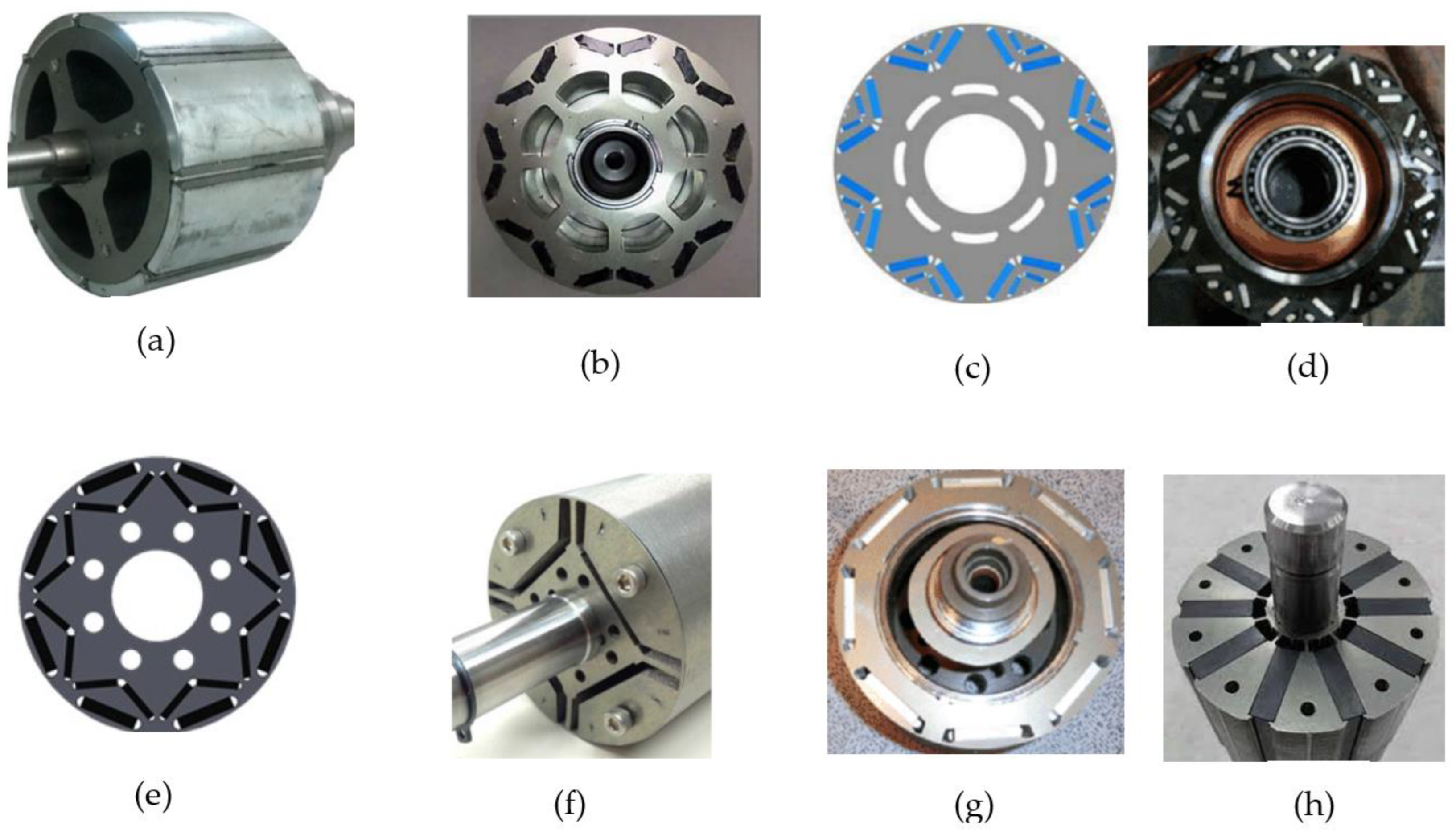


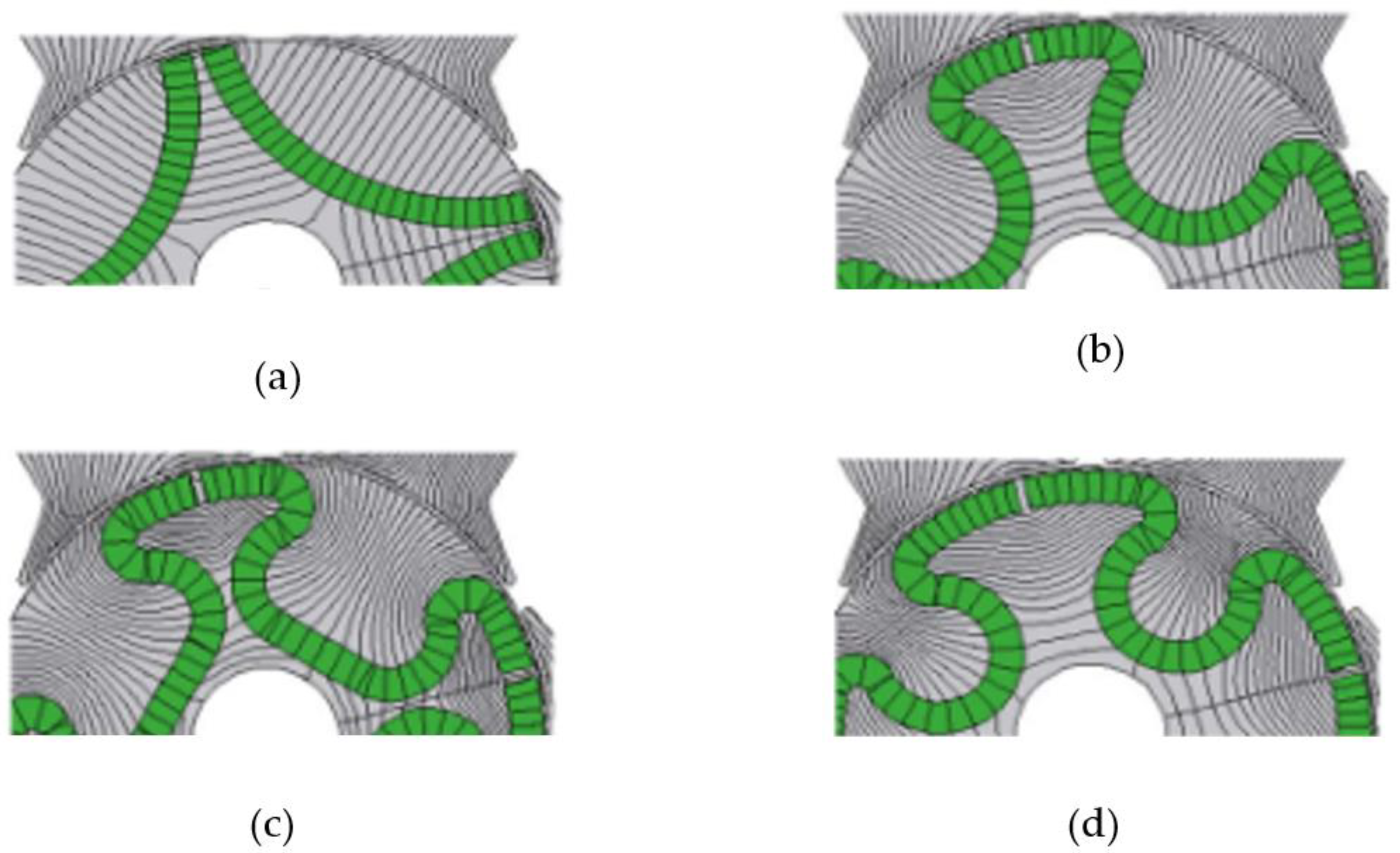
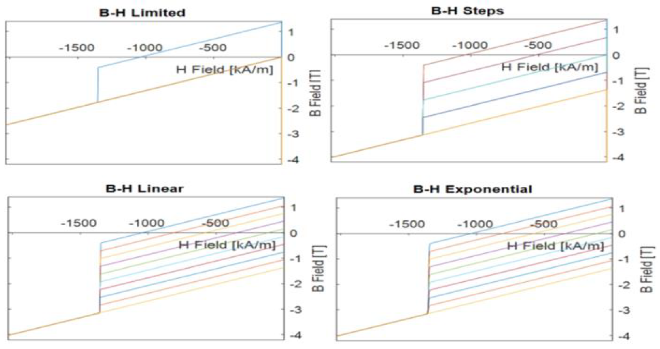
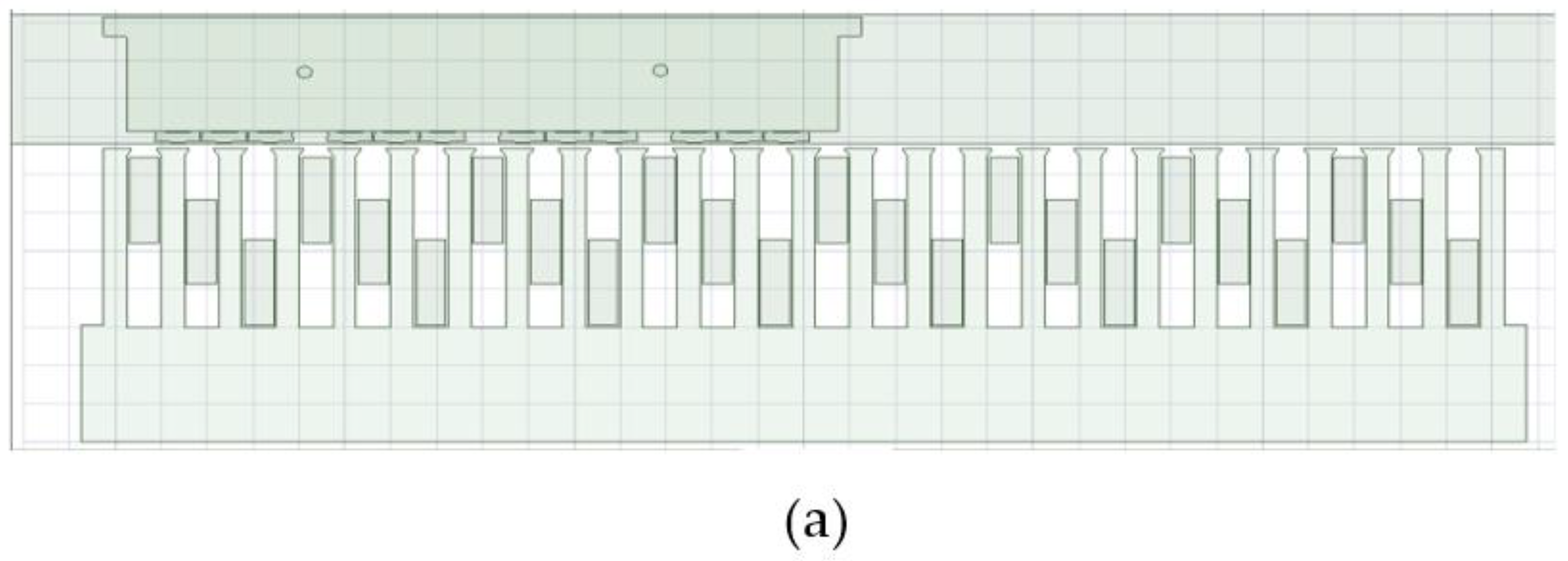
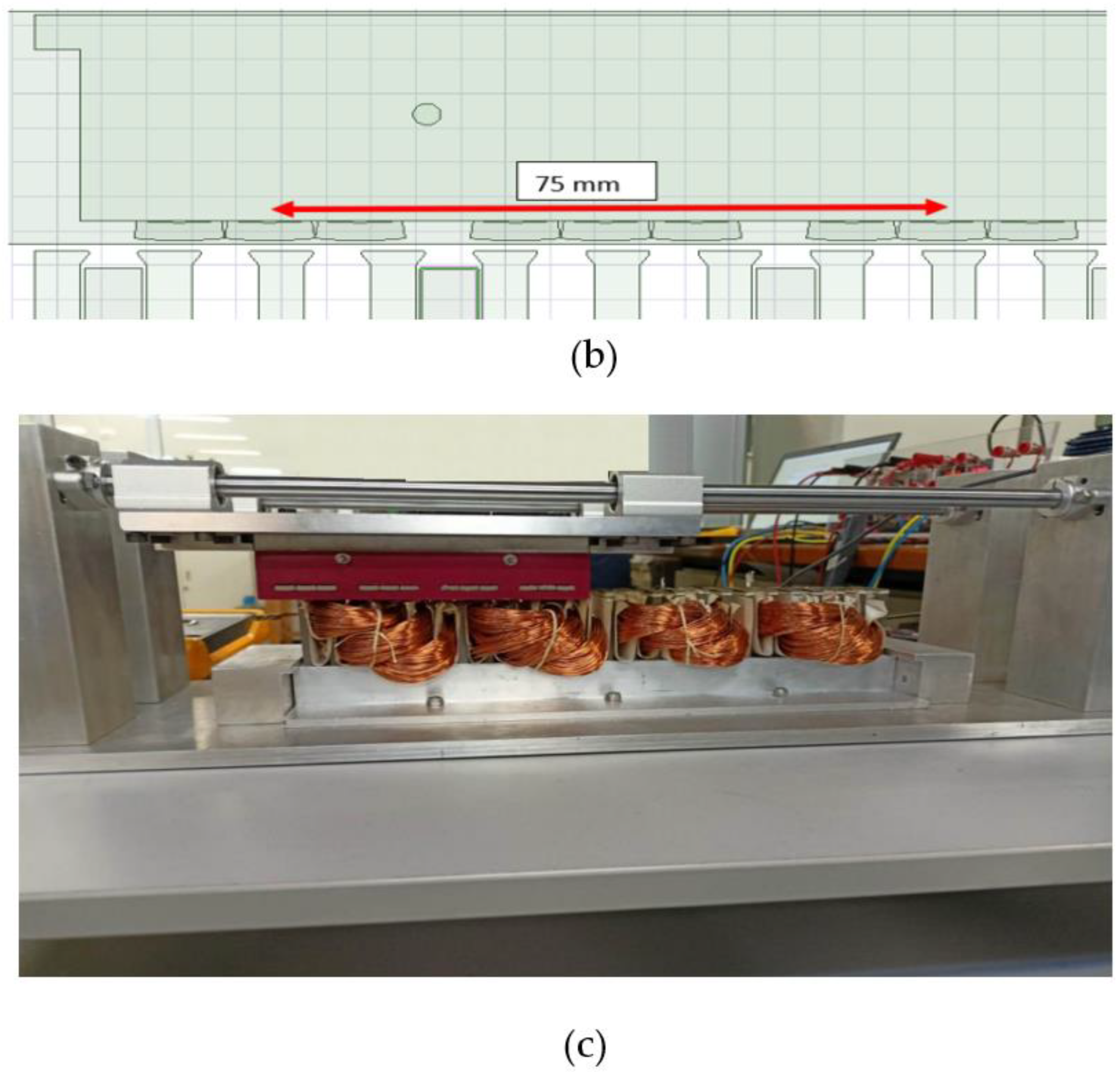



| f=1kHz | f=5kHz | f=10kHz | f=15kHz | f=20kHz | |||||
|---|---|---|---|---|---|---|---|---|---|
| Excitation (At) |
Losses (W) |
Excitation (At) |
Losses (W) |
Excitation (At) |
Losses (W) |
Excitation (At) |
Losses (W) |
Excitation (At) |
Losses (W) |
| 8 | 0.1 | 9 | 0.1 | 8 | 0.2 | 9 | 0.3 | 9 | 0.5 |
| 12 | 0.2 | 13 | 0.2 | 11 | 0.3 | 11 | 0.4 | 12 | 0.8 |
| 14 | 0.3 | 16 | 0.4 | 14 | 0.5 | 15 | 1 | 15 | 1.5 |
| 18 | 0.4 | 19 | 0.5 | 17 | 0.7 | 18 | 1.5 | 19 | 2.1 |
| 20 | 0.5 | 22 | 0.8 | 21 | 1.2 | 22 | 2.1 | 23 | 3.1 |
| 24 | 0.6 | 25 | 1 | 24 | 1.5 | 25 | 2.8 | 26 | 4 |
| 26 | 0.7 | 28 | 1.2 | 27 | 2 | 29 | 4 | 29 | 5.8 |
| 28 | 0.8 | 31 | 1.8 | 30 | 2.8 | 32 | 4.5 | 34 | 6.5 |
Disclaimer/Publisher’s Note: The statements, opinions and data contained in all publications are solely those of the individual author(s) and contributor(s) and not of MDPI and/or the editor(s). MDPI and/or the editor(s) disclaim responsibility for any injury to people or property resulting from any ideas, methods, instructions or products referred to in the content. |
© 2023 by the authors. Licensee MDPI, Basel, Switzerland. This article is an open access article distributed under the terms and conditions of the Creative Commons Attribution (CC BY) license (http://creativecommons.org/licenses/by/4.0/).


