Submitted:
22 December 2023
Posted:
25 December 2023
You are already at the latest version
Abstract
Keywords:
1. Introduction
2. Materials and Methods
2.1. Materials and Manufacturing Method
2-2. Corrosion Test
| Ions | Concentration (mM) | Ions | Concentration (mM) |
|---|---|---|---|
| Mg2+ | 15.0 | HPO42- | 10.0 |
| K+ | 50.0 | HCO3- | 42.0 |
| Na+ | 1420.0 | Cl- | 1478.0 |
| Ca2+ | 25.0 | SO42- | 5.0 |
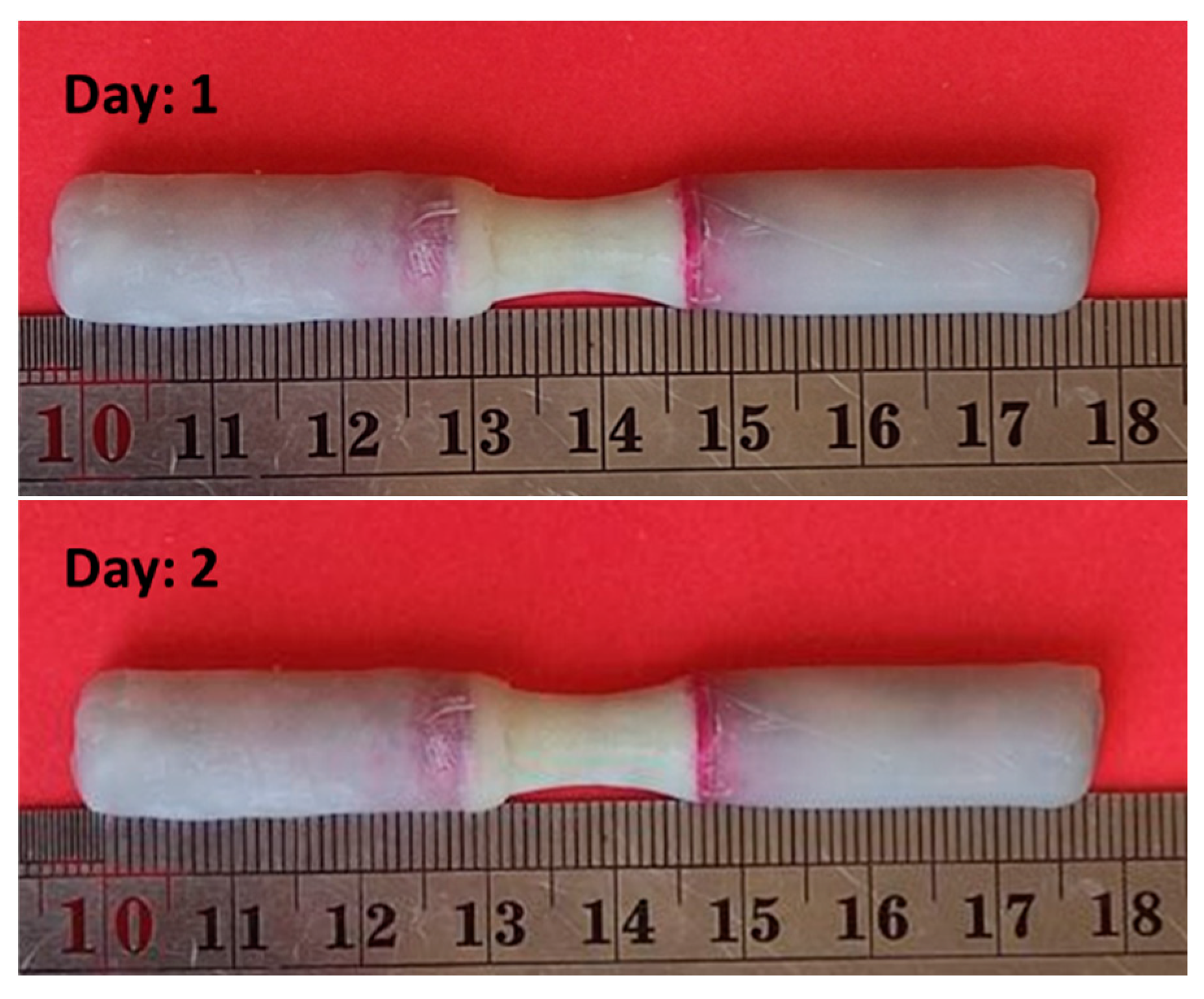
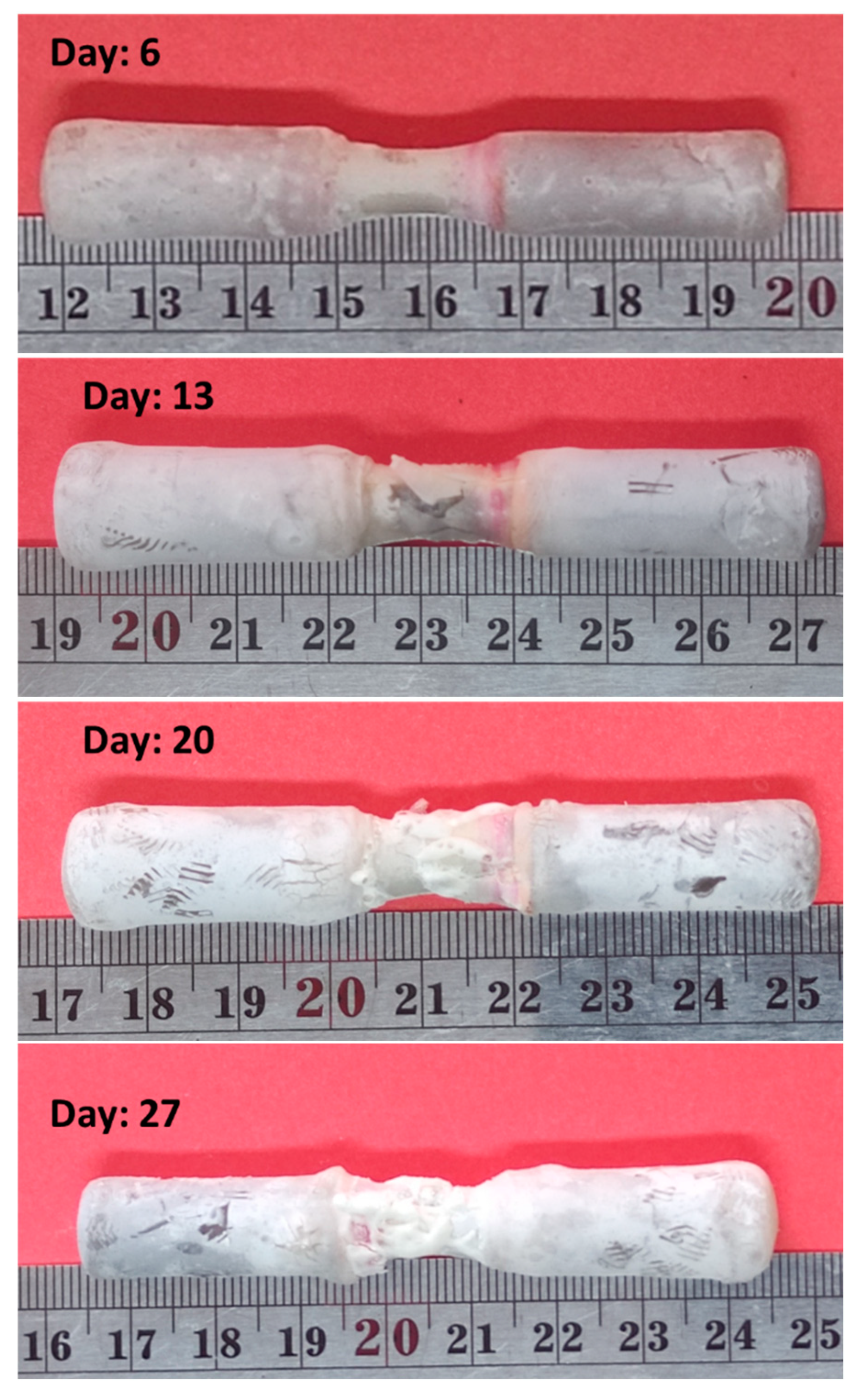
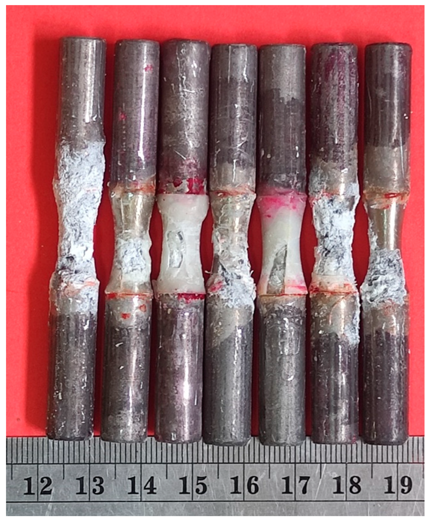
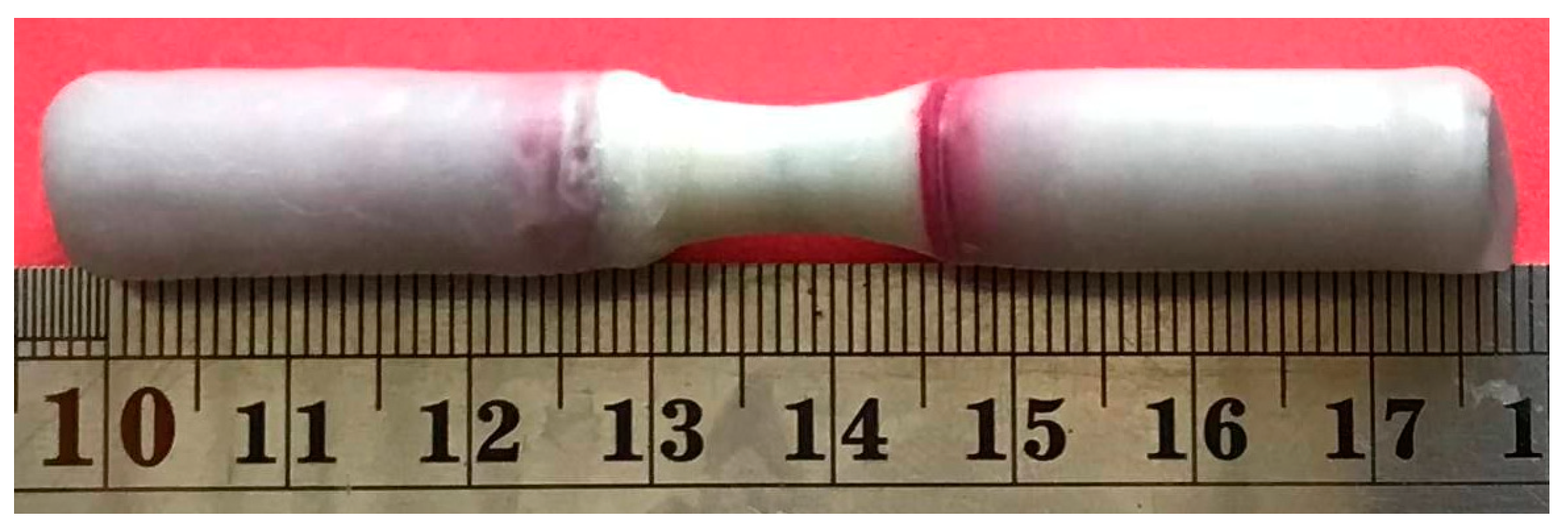
2.3. Fatigue Test
2.4. Fracture Surface Analyze
3. Results
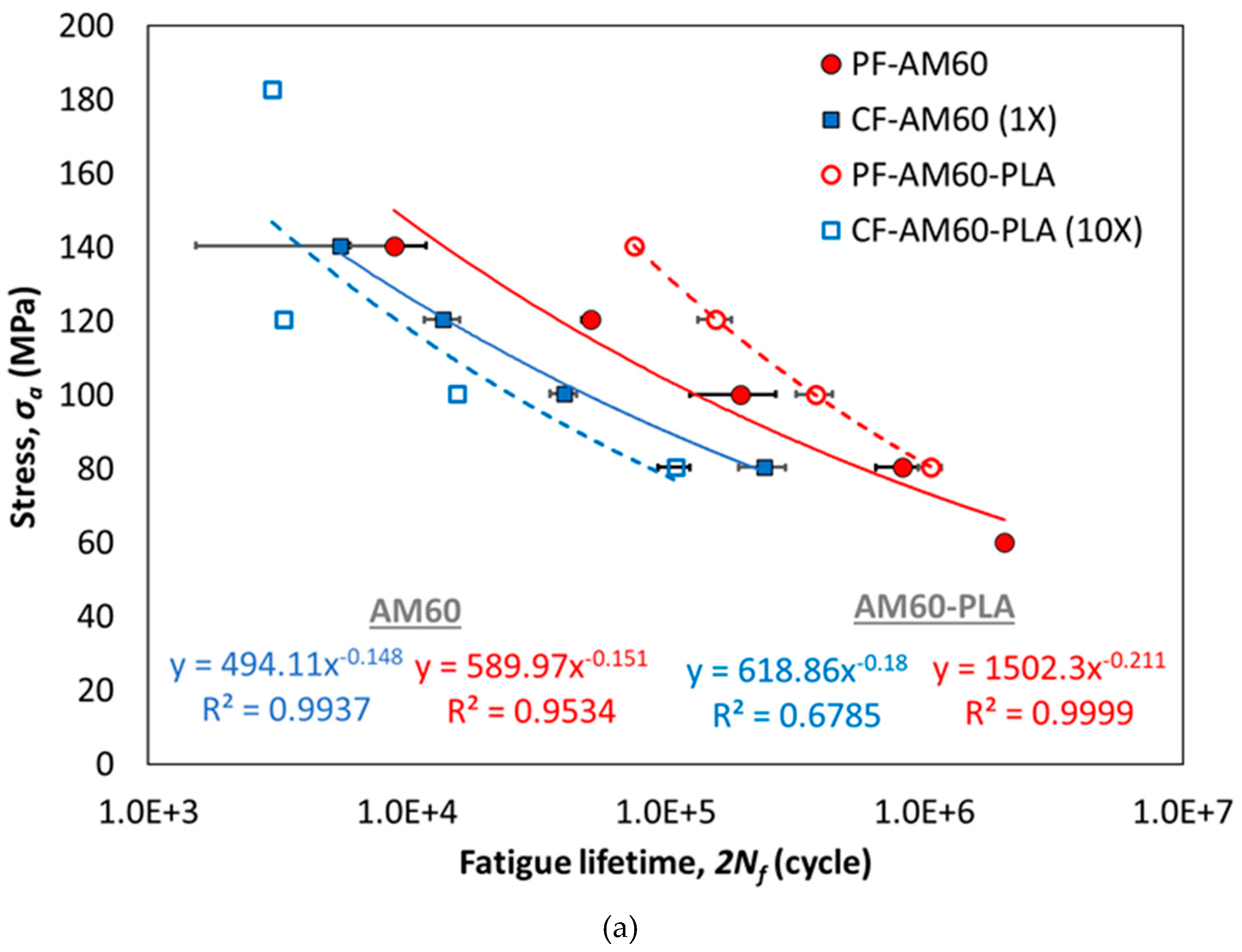
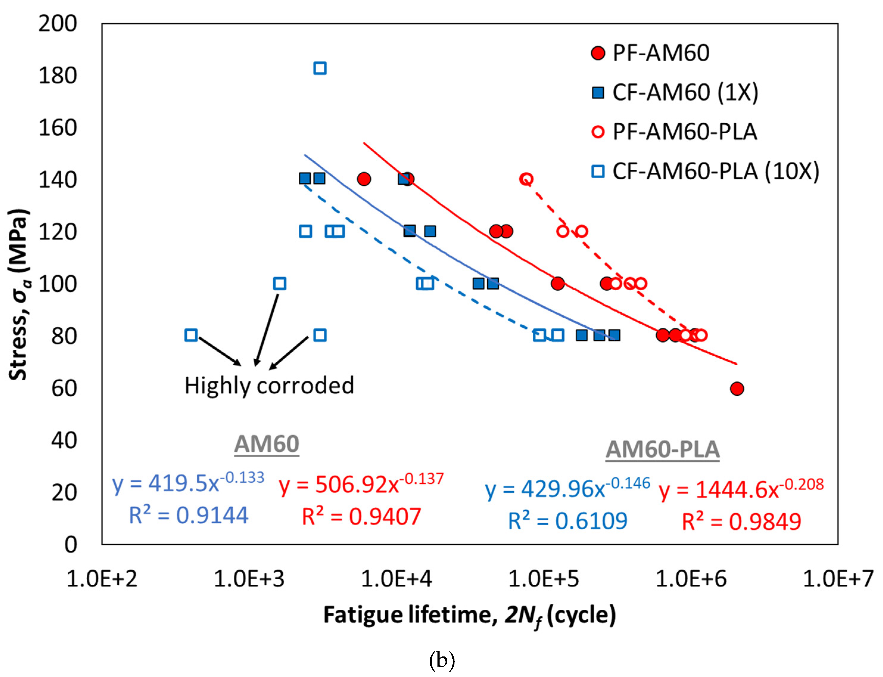
| Test Conditions | All Data | Average Data | ||||
|---|---|---|---|---|---|---|
| (MPa) | b | R2 | (MPa) | b | R2 | |
| PF-AM60 | 506.92 | -0.137 | 0.9407 | 589.97 | -0.151 | 0.9534 |
| CF-AM60 | 419.50 | -0.133 | 0.9144 | 494.11 | -0.148 | 0.9999 |
| PF-AM60-PLA | 1444.60 | -0.208 | 0.9849 | 1502.30 | -0.211 | 0.9999 |
| CF-AM60-PLA | 429.96 | -0.146 | 0.6109 | 618.86 | -0.180 | 0.6785 |


4. Conclusions
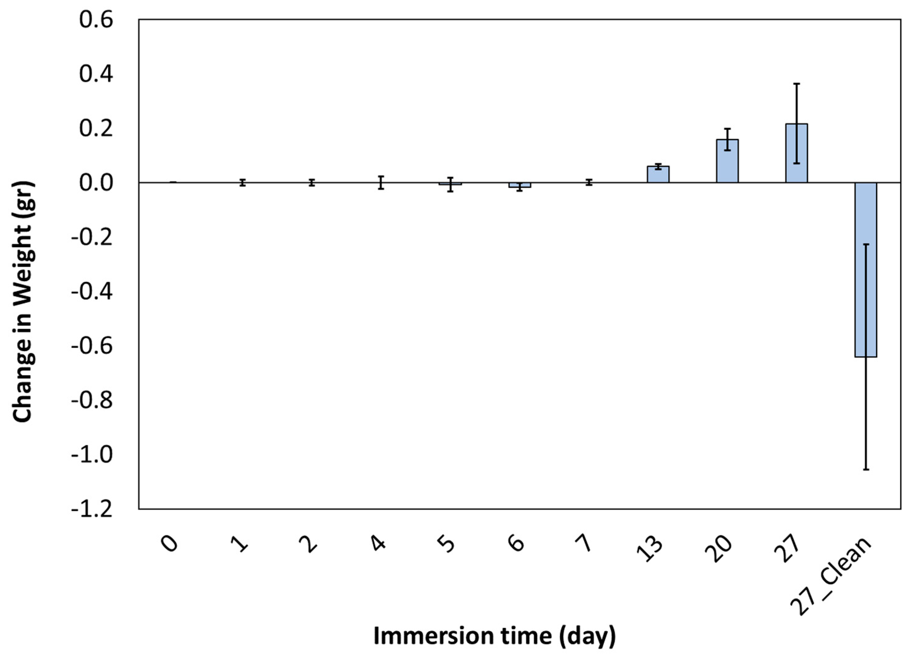
- Due to corrosion, the weight of the sample decreased by 35%.
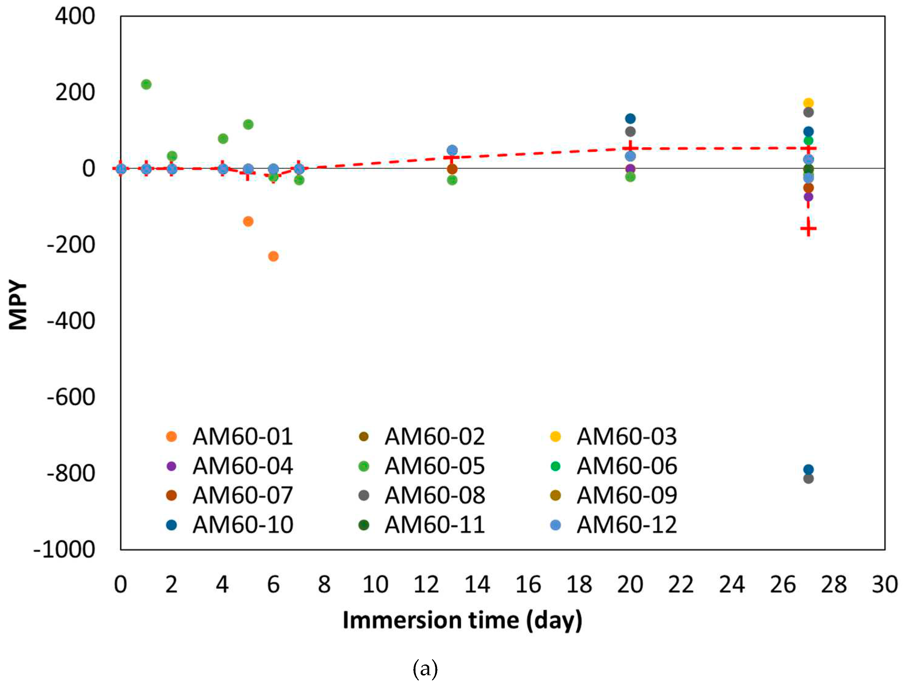
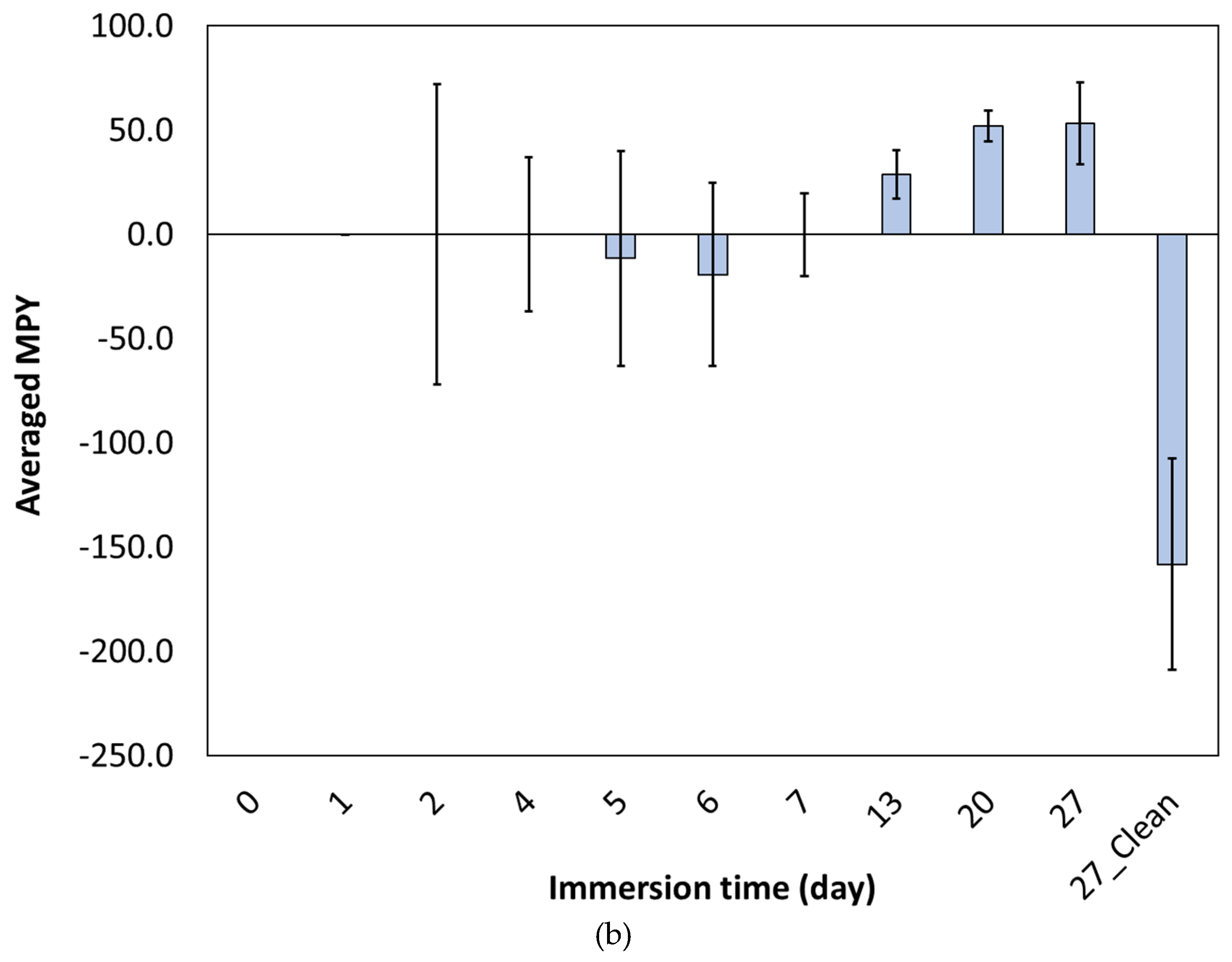
- The corrosion rate decreased in the first 7 days and then increased.
- Compared to the PF-AM60 sample, the PF-AM60-PLA sample on average had a 49% increase in fatigue lifetime.
- Despite using a 10 times stronger solution, the fatigue lifetime of CF-AM60-PLA samples is reduced by only 35% compared to CF-AM60 samples.
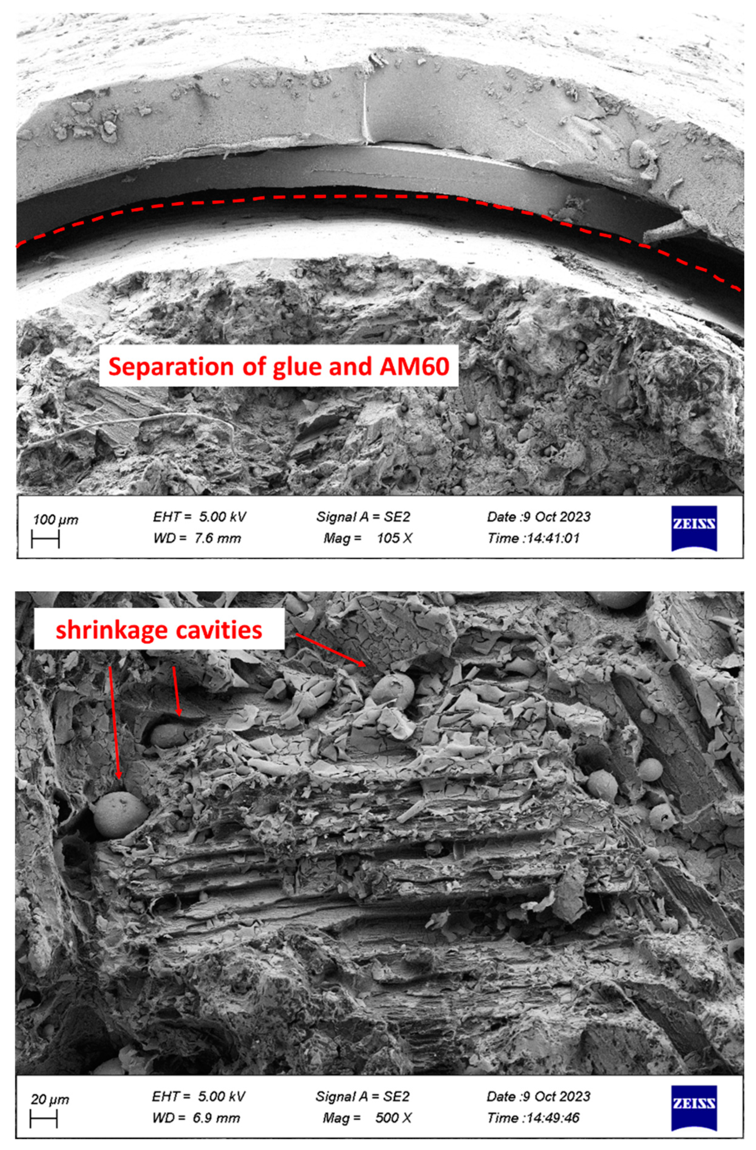
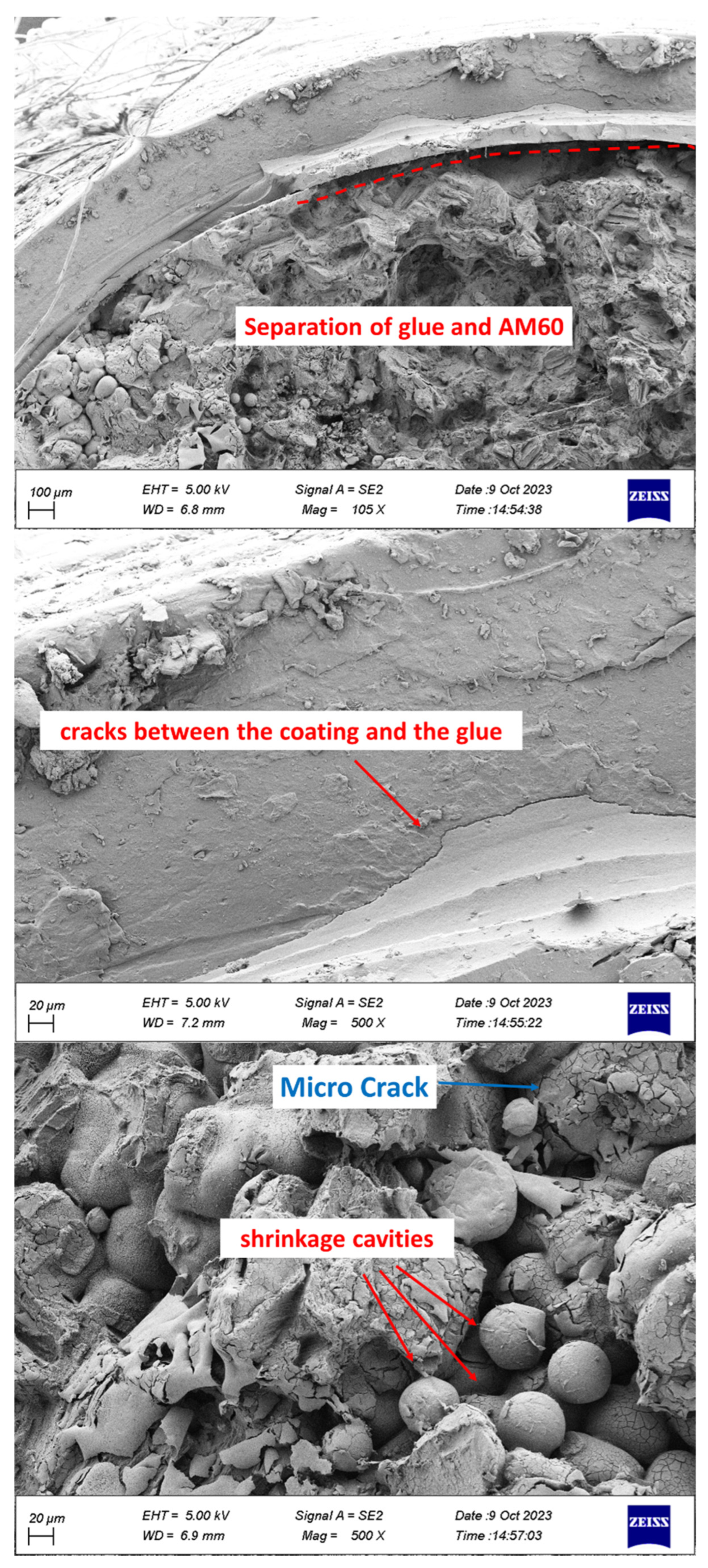
- Separation of coating from glue and glue from Mg was observed.
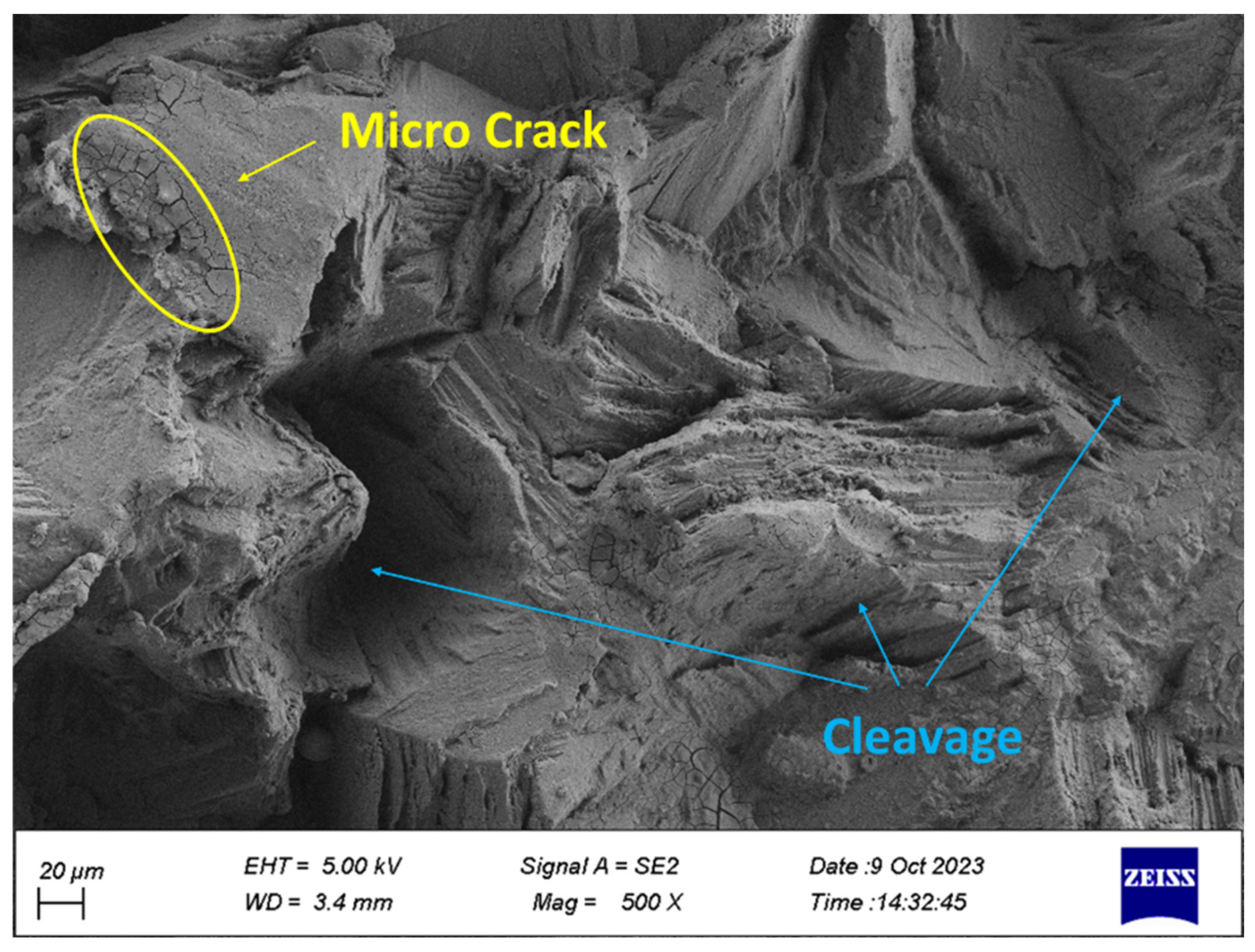
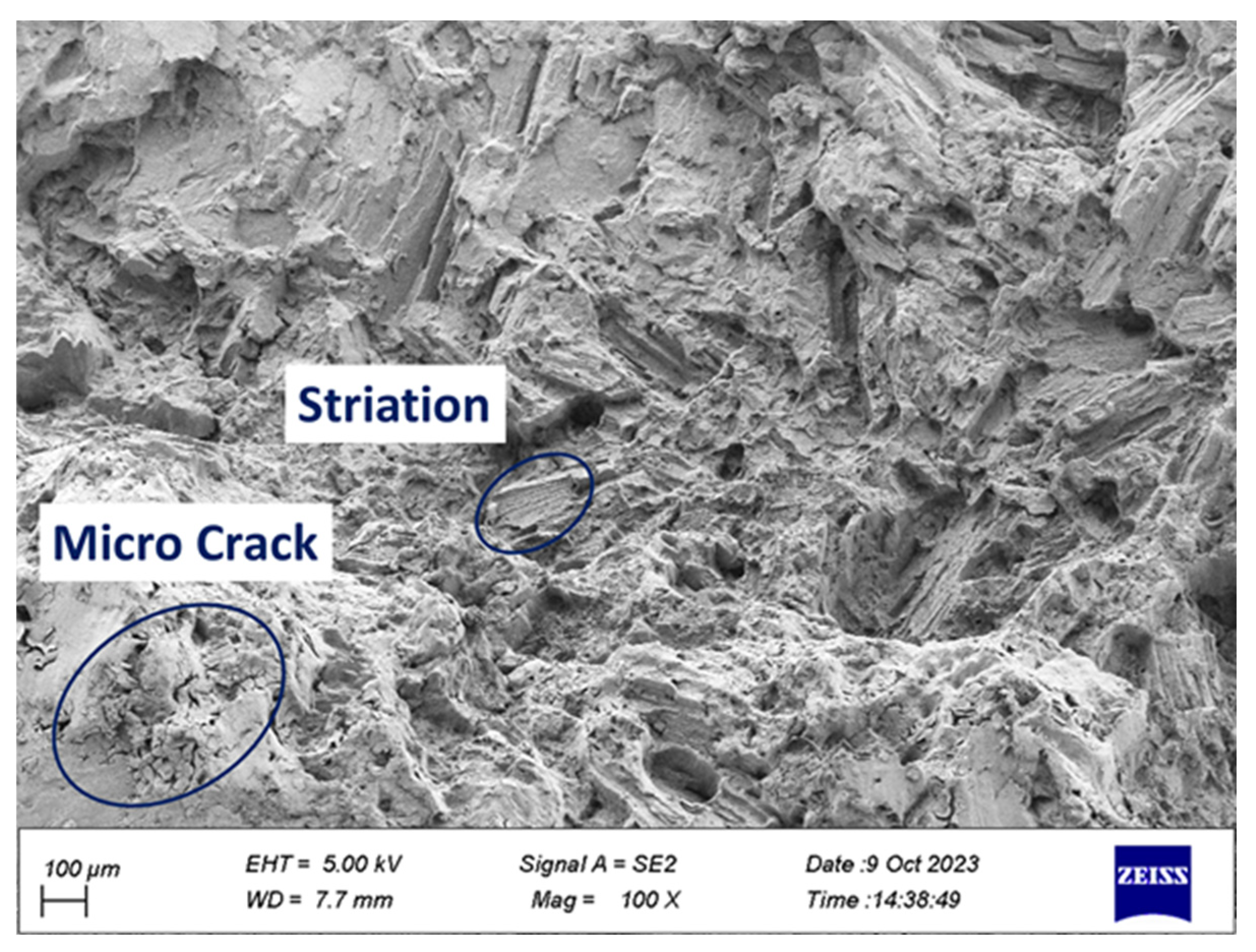
- Cleavage plates caused by brittle fracture and striations caused by fatigue load were seen on the failure surface.
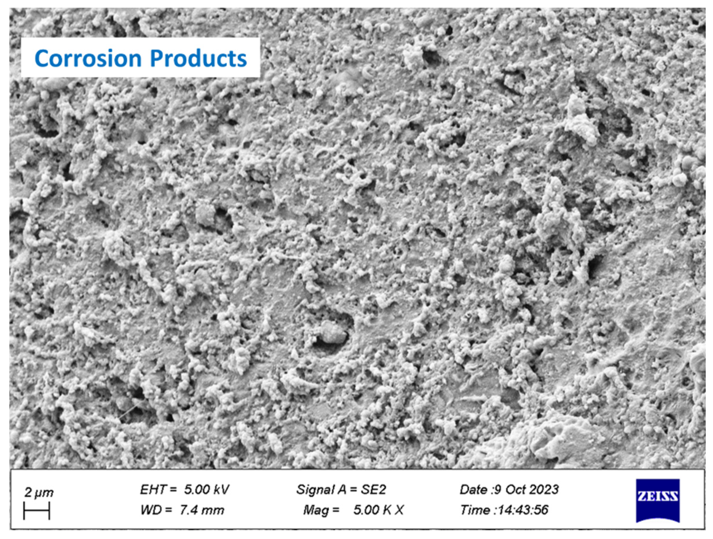
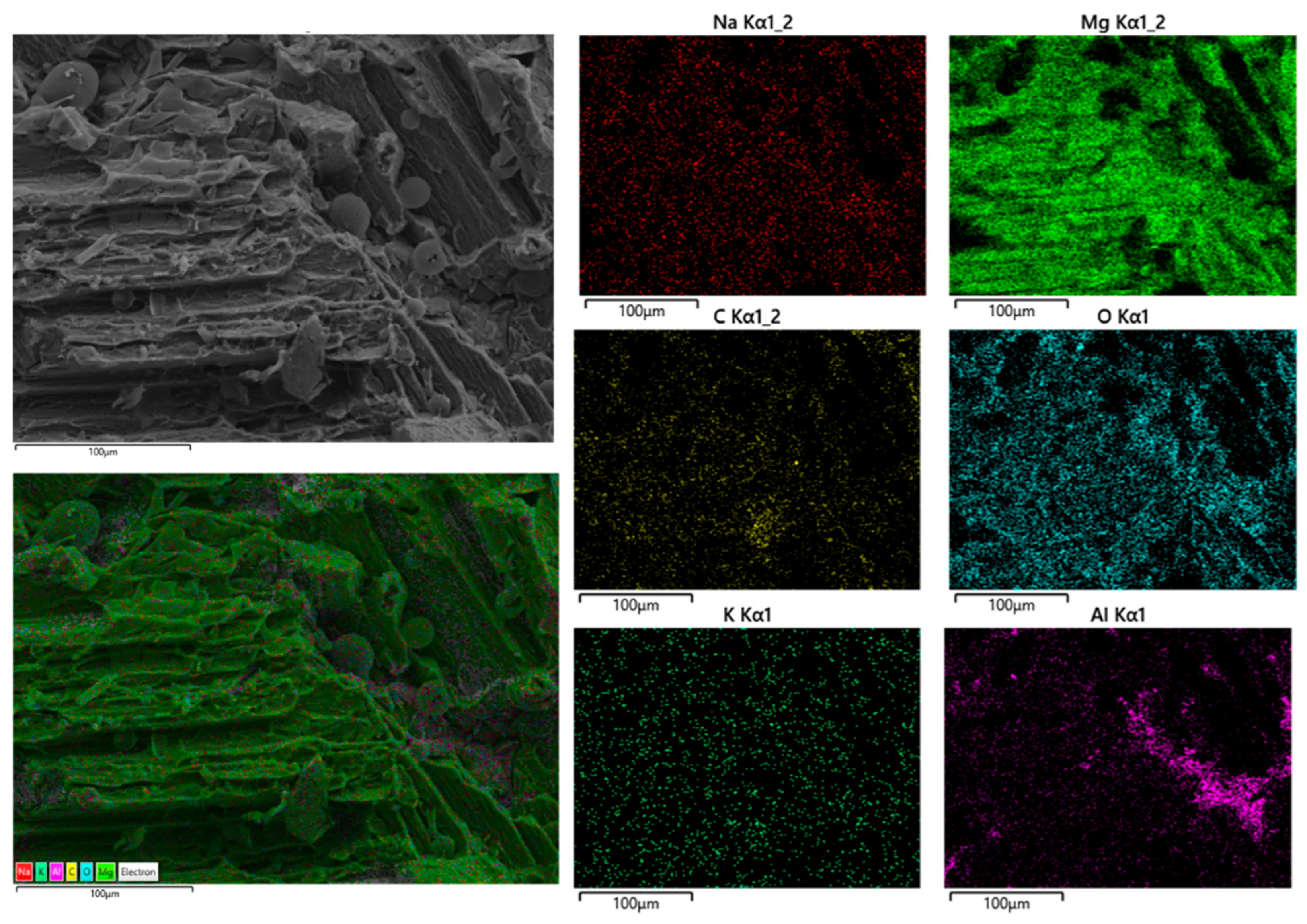
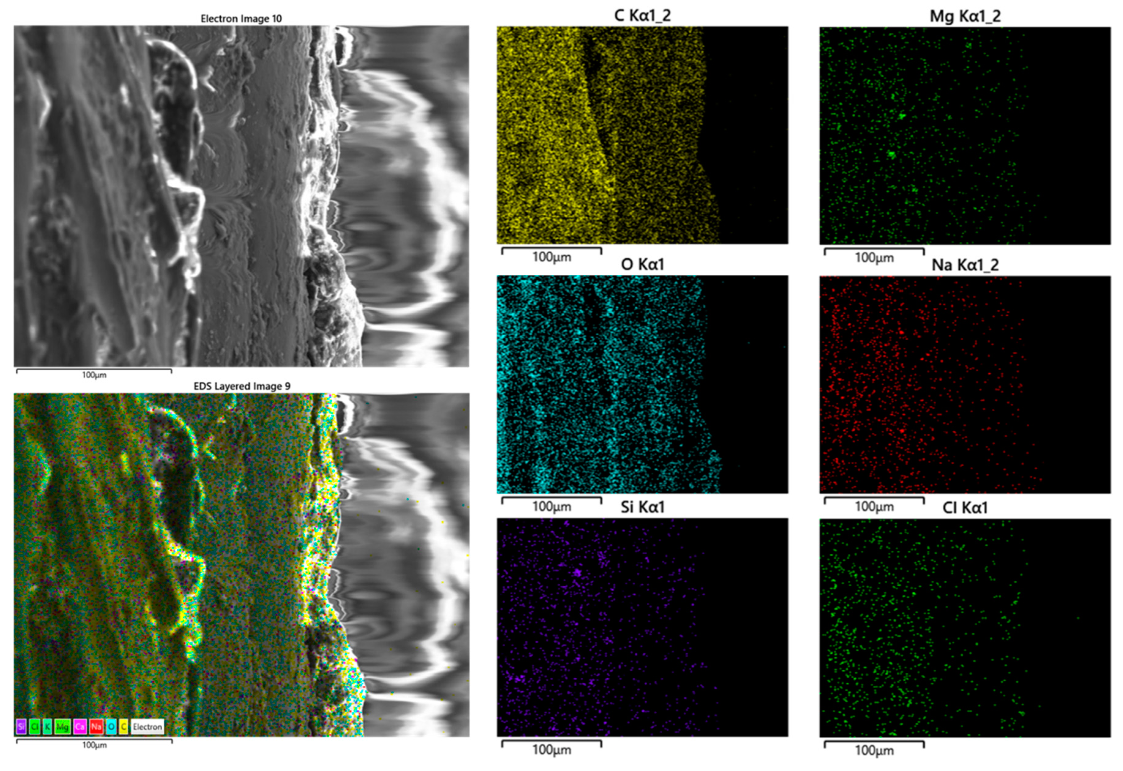
- Corrosion products including microcracks and holes were seen on the fracture surfaces of CF samples, which caused stress concentration and crack growth.
- Holes caused by the release of gases were observed in the coating.
Author Contributions
References
- Wu C. S., Zhang Z., Cao F. H., Zhang L. J, Zhang J. Q., and C. N. Cao, “Study on the anodizing of AZ31 magnesium alloys in alkaline borate solutions”, Applied Surface Science, vol. 253, pp. 3893–3898, 2007. [CrossRef]
- Moosbrugger C., Engineering Properties of Magnesium Alloys, ASM International, 2017.
- Zartner P., Cesnjevar R., Singer H. and Weyand M., “First successful implantation of a bio-degradable metal stent into the left pulmonary artery of a preterm baby”, Catheter Cardiovascular Interventions, vol. 66, pp. 590–594, 2005. [CrossRef]
- Heublein B., Rohde R., Kaese V., Niemeyer M. and Hartung W., “A. Haverich, Bio-corrosion of magnesium alloys: a new principle in cardiovascular implant technology”, Heart, vol. 89, pp. 651-656, 2003. [CrossRef]
- Baril G., Blanc C., and Pebere N., “AC impedance spectroscopy in characterizing time-dependent corrosion of AZ91 and AM50 magnesium alloys characterization with respect to their microstructures”, Journal of The Electrochemical Society, vol. 148, no. 12, 2001. [CrossRef]
- Staiger M. P., Pietak A. M., Huadmai J. and Dias G., “Magnesium and its alloys as orthopedic biomaterials: A review”, Biomaterials, vol. 27, no. 9, pp. 1728–1734, 2006. [CrossRef]
- Song Y., Liu D., Tang W., Dong K., Shan D. and Han E., “Comparison of the corrosion behavior of AM60 Mg alloy with and without self-healing coating in atmospheric environment”, Journal of Magnesium and Alloys. vol. 9, pp. 1220–1232, 2021. [CrossRef]
- Liu W., Cao F., Jia B., Zheng L., Zhang J., Cao C., and Li X., “Corrosion behavior of AM60 magnesium alloys containing Ce or La under thin electrolyte layers. Part 2: Corrosion product and characterization”, Corrosion Science. vol. 52, pp. 639–650, 2010. [CrossRef]
- Matsubara H., Ichige Y., Fujita K., Nishiyama H., and Hodouchi K., “Effect of impurity Fe on corrosion behavior of AM50 and AM60 magnesium alloys”, Corrosion Science, vol. 66, pp. 203–210, 2013. [CrossRef]
- Xie Z., Luo Z., Yang Q., Chen T., Tan S., Wang Y., and Luo Y., “Improving anti-wear and anti-corrosion properties of AM60 magnesium alloy by ion implantation and Al/AlN/CrAlN/CrN/MoS2 gradient duplex coating”, Vacuum. vol. 101, pp. 171–176, 2014. [CrossRef]
- Kumar D., “Effect of hydroxyapatite (HA) addition on microstructure, corrosion resistance of AZ91D”, AJ62 and AM60 alloys, vol. 50, pp. 582-584, 2022. [CrossRef]
- Chenghao L., Shusen W., Naibao H., Zhihong Z., Shuchun Z., and Jing R., “Effects of Lanthanum and Cerium Mixed Rare Earth Metal on Abrasion and Corrosion Resistance of AM60 Magnesium Alloy Liang, Rare Metal Materials and Engineering”. vol. 44, no. 3, pp. 521–526, 2015. [CrossRef]
- Ikpi M.E., Dong J., and Ke W., “Electrochemical Investigation of the Galvanic Corrosion of AM60 and AD62 Magnesium Alloy in 0.1 M NaCl Solution Magdalene”, International journal of electrochemical science. vol. 10, pp. 552–563, 2015. [CrossRef]
- Liu D., Song Y., Shan D., and Han E., “Comparison of the inhibition effect of four inhibitors on the corrosion behavior of AM60 magnesium alloy”, International Journal of Electrochemical Science, vol. 13, pp. 2219–2235, 2019. [CrossRef]
- Jin-ling Z., Yang-li L., Jing Z., Zhi-yong F., and She-bin W., “Kinetic study on the corrosion behavior of AM60 magnesium alloy with different Nd contents”, Journal of Alloys and Compounds. vol. 629, pp. 290–296, 2015. [CrossRef]
- Akbaripanah F., Fereshteh-Saniee F., Mahmudi R., and Kim H.K., “The influences of extrusion and equal channel angular pressing (ECAP) processes on the fatigue behavior of AM60 magnesium alloy”, Materials Science & Engineering A. vol. 565, pp. 308–316, 2013. [CrossRef]
- Khan S.A., Miyashita Y., Mutoh Y., and Koike T., “Fatigue behavior of anodized AM60 magnesium alloy under humid environment”, Materials Science and Engineering: A, vol. 498, pp.377-383, 2008. [CrossRef]
- Hiromoto S., Tomozawa M., and Maruyama N., “Fatigue property of a bioabsorbable magnesium alloy with a hydroxyapatite coating formed by a chemical solution deposition”, Journal of the Mechanical Behavior of Biomedical Materials. vol. 25, p. 2013. [CrossRef]
- Singh Raman R.K., Jafari S., and Harandi S.E., “Corrosion fatigue fracture of magnesium alloys in bioimplant applications: A review”, Engineering Fracture Mechanics, vol. 137, pp.97-108, 2015. [CrossRef]
- Uematsu Y., Kakiuchi T., Teratani T., Harada Y., and Tokaji K., “Improvement of corrosion fatigue strength of magnesium alloy by multilayer diamond-like carbon coatings, Improvement of corrosion fatigue strength of magnesium alloy by multilayer diamond-like carbon coatings”, vol. 205, pp.2778-2784, 2011. [CrossRef]
- AlamKhan S., Bhuiyan M.S., Miyashita Y., Mutoh Y., and Koike T., “Corrosion fatigue behavior of die-cast and shot-blasted AM60 magnesium alloy”, Materials Science and Engineering A. vol. 528, pp. 1961–1966, 2011. [CrossRef]
- Ishihara S., Namito T., Notoya H., and Okada A., “The corrosion fatigue resistance of an electrolytically-plated magnesium alloy”, International Journal of Fatigue, vol. 32, pp. 1299-1305, 2010. [CrossRef]
- Talesh S.A.A., and Azadi M., “High-cycle fatigue testing on AM60 magnesium alloy samples for as-received and pre-corroded conditions in simulated body fluid”, Journal of Materials Research and Technology. vol. 27, pp. 1922–1934, 2023. [CrossRef]
- Antunes R.A., and De Oliveira M.C.L, “Corrosion fatigue of biomedical metallic alloys: Mechanisms and mitigation”, Acta Biomaterialia. vol. 8, pp. 937–962, 2012. [CrossRef]
- Delavar H., Mostahsan A.J., and Ibrahim H., “Corrosion and corrosion-fatigue behavior of magnesium metal matrix composites for bio-implant applications: A review”, Journal of Magnesium and Alloys. vol. 11, pp. 1125–1161, 2023. [CrossRef]
- Yadav V.K., Gaur V., and Singh I.V., “Corrosion-fatigue behavior of welded aluminum alloy 2024-T3”, International Journal of Fatigue. vol. 173, pp. 107675, 2023. [CrossRef]
- Shi Y., Yang L., Zhang Q., Zhu X., Song Z., and Liu H., “A novel MAO-PLA coating on zinc alloy for potential orthopedic implant material”, Materials Letters. vol. 317, 132058, 2022. [CrossRef]
- Anand N., and Pal K., “Evaluation of biodegradable Zn–1Mg–1Mn and Zn–1Mg–1Mn-1HA composites with a polymer-ceramics coating of PLA/HA/TiO2 for orthopaedic applications”, Journal of the Mechanical Behavior of Biomedical Materials. vol. 136, 105470, 2022. [CrossRef]
- Wang A., Venezuela J., and Centre M.S.D., “Enhancing the corrodibility of biodegradable iron and zinc using poly (lactic) acid (PLA) coating for temporary medical implant applications”, Progress in Organic Coatings journal. vol. 174, 107301, 2023. [CrossRef]
- Beyzavi A.H., Azadi M., Azadi M., Dezianian S., and Talebsafa V., “Bio-polymer coatings fabricated on AM60 magnesium alloys by fused deposition modeling 3D-printing to investigate electrochemical behavior”, Materials Letters. vol. 337,133935, 2023. [CrossRef]
- ASTM Standard G-31, Standard Practice for Laboratory Immersion Corrosion Testing of Metals, Annual Book of ASTM Standards, ASTM International West Conshohocken, USA, 2021.
- Simulated body fluid catalog, Pardis Pajouhesh Fanavaran Yazd Company, Yazd Science and Technology Park, Yazd, Iran, 2023.
- Rezanezhad S., and Azadi M., “Amazing epsilon-shaped trend for fretting fatigue characteristics in AM60 magnesium alloy under stress-controlled cyclic conditions at bending loads with zero mean stress”, Plos One, vol. 18, 0281263, 2023. [CrossRef]
- Dezianian S., and Azadi M., “Multi-Material Metamaterial Topology Optimization to Minimize the Compliance and the Constraint of Weight: Application of Non-Pneumatic Tire Additive-Manufactured with PLA/TPU Polymers”, Polymers, vol. 15, 1927, 2023. [CrossRef]
- Dezianian S., Azadi M., and Razavi S.M.J., “Topology optimization on metamaterial cells for replacement possibility in non-pneumatic tire and the capability of 3D-printing”, Plos One, vol. 18, 2023. [CrossRef]
- Rezanezhad S., and Azadi M., “Impact of 3D-printed PLA coatings on the mechanical and adhesion properties of AM60 magnesium alloys”, Composites Part C, vol. 12, 100415, 2023. [CrossRef]
- Azadi M., Dadashi A., Dezianian S., Kianifar M., Torkaman S., and Chiyani M., “High-cycle bending fatigue properties of additive-manufactured ABS and PLA polymers fabricated by fused deposition modeling 3D-printing.” Forces Mech, vol.3, 100016, 2021. [CrossRef]
- Rudawska A., Sarna-Boś K., Rudawska A., Różyło-Kalinowska I., and Chałas R., “Biological and chemical properties of cured epoxy resins”, Research Square, 2021. [CrossRef]
- Muñoz M., Torres B., Mohedano M., Matykina E., Arrabal R., López A.J., and Rams J., “PLA deposition on surface treated magnesium alloy: Adhesion, toughness and corrosion behavior” Surf Coatings Technol, vol. 388, 125593, 2020. [CrossRef]
- Azadi M., and Parast M., “Data analysis of high-cycle fatigue testing on piston aluminum-silicon alloys under various conditions: Wear, lubrication, corrosion, nano-particles, heat-treating, and stress”, Data in Brief, vol. 41, 107984, 2022. [CrossRef]
- Metallic materials - rotating bar bending fatigue testing, Standard No. ISO 1143, ISO International Standard, 2010.
- Rotating bar bending fatigue test, Standard No. DIN EN 50113, DIN Standard, 1982.
- Standard practice for laboratory immersion corrosion testing of metals, ASTM International, Designation: G 31 – 72 (Reapproved 2004).
- Oliya A. Y. P., Azadi M., Parast M. S. A., and Mokhtarishirazabad M., “Effect of Heat-Treating on Microstructure and High Cycle Bending Fatigue Behavior of AZ91 and AZE911 Magnesium Alloys”, Advances in Materials Science and Engineering, pp. 1–11, 2022. [CrossRef]
- Hodaeian H., Degradation of Pure Magnesium Alloys, 2013.
- Guo Z., Yang C., Zhou Z., Chen S., and Li F., “Characterization of biodegradable poly (lactic acid) porous scaffolds prepared using selective enzymatic degradation for tissue engineering”, Royal society of chemistry Advances, vol. 7, 34063, 2017. [CrossRef]
- Hasanpur E., Ghazavizadeh A., Sadeghi A., and Haboussi M., “In vitro corrosion study of PLA/Mg composites for cardiovascular stent applications”, Journal of the Mechanical Behavior of Biomedical Materials, vol. 124, 104768, 2021. [CrossRef]
- Balogova A., Trebunova M., Izarikova G., Kascak L., Mitrík L., Klimova J., Feranc J., Modrak M., Hudak R., and Zivcak J., “In Vitro Degradation of Specimens Produced from PLA/PHB by Additive Manufacturing in Simulated Conditions”, Polymers, vol.13, 1542, 2021. [CrossRef]
- Redondo F., Giaroli M., Ciolino A., and Ninago M., “Preparation of Porous Poly (Lactic Acid)/Tricalcium Phosphate Composite Scaffolds for Tissue Engineering”, Biointerface Research in Applied Chemistry, vol. 12, 2022, pp. 5610 – 5624, 2021. http://dx.doi.org/10.33263/BRIAC124.56105624.
- Alksne M., Kalvaityte M., Simoliunas E., Rinkunaite I., Gendviliene I., Locs J., Rutkunas V., and Bukelskiene V., “In vitro comparison of 3D printed polylactic acid/hydroxyapatite and polylactic acid/bio-glass composite scaffolds: Insights into materials for bone regeneration”, Journal of the Mechanical Behavior of Biomedical Materials, vol. 104, 103641, 2020. [CrossRef]
- Chor A., Gonçalves R., Costa A., Farina M., Ponche A., Sirelli L., Schrodj G., Gree S., Andrade L., Anselme K., and Dias M., “In Vitro Degradation of Electro-spun Poly (Lactic-Co-Glycolic Acid) (PLGA) for Oral Mucosa Regeneration”, Polymers, vol. 12, 1853, 2020. [CrossRef]
- Voicu M.E., Demetrescu I., Dorobantu A., Enachescu M., Buica G.O., and Ionita D., “Interaction of Mg Alloy with PLA Electro-spun Nanofibers Coating in Understanding Changes of Corrosion”, Nanomaterials, vol. 12, 12081369, 2022. [CrossRef]
- Shi P., Niu B., Shanshan E., Chen Y., and Li Q., “Preparation and characterization of PLA coating and PLA/MAO composite coatings on AZ31 magnesium alloy for improvement of corrosion resistance”, Surface and Coatings Technology, vol. 262, pp. 26-32, 2015. [CrossRef]
- Basquin O.H., “The exponential law of endurance tests”, Proceeding of American Society of Testing and Materials, 1910.
- Ghazizadeh E., Jabbari A.H., and Sedighi M., “In vitro corrosion fatigue behavior of biodegradable Mg/HA composite in simulated body fluid.”, Journal of Magnesium and Alloys, vol. 9, pp.2169-2184, 2021. [CrossRef]
- Stephens R., Fatemi A., Stephens R., and Fuchs H., “Metal fatigue in engineering”, John Wiley and Sons, 2000.
- Mokhtarishirazabad M., Azadi M., Farrahi G.H., Winter G., and Eichlseder W., “Improvement of high temperature fatigue lifetime in AZ91 magnesium alloy by heat treatment”, Materials Science & Engineering A, vol. 588, pp. 357-365, 2013. [CrossRef]
- Farrahi G.H., Azadi M., Winter G., and Eichlseder W., “A new energy-based isothermal and thermo-mechanical fatigue lifetime prediction model for aluminum–silicon–magnesium alloy”, Fatigue & Fracture of Engineering Materials & Structures, vol. 36, pp. 1323-1335, 2013. [CrossRef]
- Jiang L., Xu F., Xu Z., Chen Y., Zhou X., Wei G., and Ge H., “Biodegradation of AZ31 and WE43 Magnesium Alloys in Simulated Body Fluid”, International journal of electrochemical science, vol. 10, pp. 10422-10432, 2015. [CrossRef]
- Liu M., Wang J., Zhu S., Zhang Y., Sun Y., Wang L., and Guan S., “Corrosion fatigue of the extruded Mg-Zn-Y-Nd alloy in simulated body fluid”, Journal of Magnesium and Alloys, vol. 8, pp. 231-240, 2020. [CrossRef]
- Azadi M., Aroo H., and Parast M.S.A., “Comparing of high-cycle fatigue lifetimes in un-corroded and corroded piston aluminum alloys in diesel engine applications”, Archives of Foundry Engineering, vol.21, pp. 89-94, 2021. [CrossRef]
- Parast M.S.A., and Azadi M., “A short evaluation of simultaneous corrosion fretting fatigue behaviors in piston aluminum-silicon alloys considering effects of nano-particles and heat-treating”, International Journal of Fatigue, vol. 168, 107403, 2023. [CrossRef]
- Nan N.Y., Ishihara S., and Goshima T., “Corrosion fatigue behavior of extruded magnesium alloy AZ31 in sodium chloride solution”, International Journal of Fatigue, vol.30, pp.1181-1188, 2008. [CrossRef]
- Bhuiyan M.S., Mutoh Y., Murai T., and Iwakami S., “Corrosion fatigue behavior of extruded magnesium alloy AZ80-T5 in a 5% NaCl environment”, Engineering Fracture Mechanics, vol. 77, pp. 1567-1576, 2010. [CrossRef]

| Mg | Mn | Zn | Si | Al | Ni | Cu |
|---|---|---|---|---|---|---|
| Bulk | 0.3 | 0.07 | 0.04 | 5.5 | 0.004 | 0.01 |
| Parameters | Speed (mm/s) | Nozzle temperature (°C) | Bed temperature (°C) | Infill in first and last layer (%) | Infill in inner layer (%) | Layer High (µm) | Nozzle diameter (mm) |
|---|---|---|---|---|---|---|---|
| Value | 50 | 245 | 60 | 100 | 50 | 50 | 0.4 |
Disclaimer/Publisher’s Note: The statements, opinions and data contained in all publications are solely those of the individual author(s) and contributor(s) and not of MDPI and/or the editor(s). MDPI and/or the editor(s) disclaim responsibility for any injury to people or property resulting from any ideas, methods, instructions or products referred to in the content. |
© 2023 by the authors. Licensee MDPI, Basel, Switzerland. This article is an open access article distributed under the terms and conditions of the Creative Commons Attribution (CC BY) license (http://creativecommons.org/licenses/by/4.0/).


