1. Introduction
Noncooperative target recognition has been a highly concerned issue in recent years, leading to modern radar performs target imaging and recognition tasks besides conventional tasks of detection and tracking [
1,
2,
3]. High range resolution profile (HRRP) achieved by larger working bandwidth is considered as a promising technology for noncooperative target identification [
4,
5]. Within HRRP radar systems, targets are discerned as a constellation of multiple scattering centers, each occupying distinct range cells, a phenomenon characteristically described as range-spread targets. Such detailed HRRP signatures markedly enhance the radar system's capabilities in both recognition and tracking of targets [
6,
7,
8].
HRRP radar can be realized by two approaches, instantaneous wideband radar and synthetic wideband radar [
9]. Instantaneous wideband radar provides big bandwidth in each pulse. It is simple on theory but expensive in cost. synthetic wideband radar divides the big bandwidth into several narrow-band pulses, therefore, more adaptable to resource-constrained platform. One practical form of synthetic wideband is the stepped-frequency waveform (SFW) technique [
10,
11,
12], which transmits a series of coherent pulse sequences whose carrier frequencies increasing or decreasing by step size. Compared to the instantaneous wideband radar, the SFW operates within narrow instantaneous bandwidth and works well under the condition of narrowband transmitter and receiver [
13]. It is widely used in satellite radar, warhead radar and even automotive radar. Unfortunately, the SFW is quite sensitive to the radial motion of the target for its large time-bandwidth product [
1,
14]. Especially in the context of high-speed target detection, the range-doppler coupling of the SFW causes range cell shift and power divergence of the target echoes.
The range cell shift and power divergence derived from the additive linear phase term and quadratic phase term of the Doppler effect has been the most concerned issues of SFW radar. Numerous studies on the SFW have been presented in recent years. These studies mainly focus on waveform designed [
4,
15,
16,
17,
18] and motion compensation [
19,
20,
21,
22,
23,
24]. In [
4], a novel SFW with double pulse repetition interval (PRI) and a Doppler phase cancellation approach is designed. It does not need estimation of the velocity and is easy to be realized. Referring to the opinion in [
4], methods by using multiple stepped-frequency pulse trains and the robust phase unwrapping theorem to estimate the range and velocity of a target were introduced in [
7,
25]. These methods can well solve the range cell shift of the SFW radar. However, they reduce the utilization of the radar signal for the fact two sets of sequent pulse trains are used to unwrap phase. In [
26,
27,
28], random stepped frequency signal is used instead of the linear frequency stepped signal to solve the range-doppler coupling of the SFW. But these methods introduce the phase compensation problem which may degenerate the correlation peak of the signal [
29,
30]. Besides, all of these methods based on waveform design suffer from the pairing of scattering centers when there are more than two targets with different velocities [
14,
23].
On the other hand, motion compensation-based methods focus on estimating the velocity of the target with the quadratic phase term of the Doppler effect, and compensating the Doppler effect with the estimated result. In [
31], an algorithm based on the maximum likelihood (ML) estimation is proposed to estimate the target velocity accurately. However, the planar search of the ML makes its computation complexity is large, causing it difficult to be implemented in real time. Velocity estimation based on cross-correlation Fast Fourier transform (FFT) and the least burst error function is invested in [
32,
33,
34]. They use an estimation strategy of coarse to fine, which firstly use cross-correlation FFT to estimate the velocity roughly and then use the least burst error rule to estimate the accurate velocity. However, these methods may be struggled in scenario with multiple targets. Exploiting the fact that the Doppler signal of the moving targets is a chirp signal whose chirp rate is decided by the velocity of the target, the discrete Chirp-Fourier transform [
35] is used to estimate the velocity of the targets by chirp-rate estimation of the Doppler frequency. However, it also needs a planar search in the frequency and chirp rate joint plane, resulting in a computational burden. The Hough Transform [
36,
37] and Lv's distribution [
38,
39] are also considered to solve the velocity estimation of the target for SFW radar. Both Hough transform and Lv’s distribution perform extremely high accuracy in estimation of the chirp rate. However, their computational burden is always mentioned in practical.
The fractional Fourier transform (FrFT) attracts a great deal of attention in recent years for its outstanding performance of chirp signal processing [
40,
41,
42]. The fast discrete algorithm proposed by Ozaktas in [
43] significantly reduces the computational complexity of the FrFT and makes it potential in signal processing. In this paper, we drew on the idea of estimating the velocity of the targets by chirp-rate estimation of the Doppler frequency based on FrFT and introduced a fast velocity estimation and compensation approach. The velocity estimation accuracy based on FrFT was quantitatively analyzed. An iterative algorithm based on golden section search (GSS), which we named iterative golden section search (IGSS), was proposed to alleviate the computational burden in the chirp rate domain. The proposed method showes a significant estimation accuracy and is suitable for the scenarios of multiple targets.
The main contributions are summarized as follows.
- 1)
We present a novel velocity estimation and compensation approach based on FrFT for SFW radar. It exploits the fact that the Doppler effect of the moving targets is a chirp signal whose chirp rate is decided by the velocity of the target. The The FrFT accurately determines this chirp rate by synthesizing the chirp signals in an optimal sequence. We have conducted a thorough quantitative analysis to validate the precision of our approach.
- 2)
We propose a rapid and precise iterative algorithm for the FrFT-based velocity estimation that minimizes computational demands without detracting from the estimation's accuracy. This innovative algorithm utilizes the golden section search (GSS) method, optimizing computational efficiency in pinpointing the FrFT's optimal order.
- 3)
To accommodate scenarios involving multiple targets, we develop an Improved Golden Section Search (IGSS). This enhancement introduces an additional looping mechanism to the GSS, enabling the IGSS to iteratively estimate velocities for individual scattering centers, thus refining the approach for more complex targeting situations.
The rest of the paper is organized as follows:
Section 2 provides a detailed description of the beat signal of the SFW radar when detecting moving targets.
Section 3 describes the framework of the proposed approach and derives the velocity accuracy that the FrFT can achieve.
Section 4 introduces the velocity estimation algorithm proposed in this paper.
Section 5 provides simulations to verify the proposed approach. Conclusions are formed in
Section 6.
2. Principle of The SFCW Radar
Without loss of generality, we select continuous wave SFW radar as an example. Besides, the proposed approach is also suitable for stepped-frequency chirp waveform radar. According to the principle of the SFW radar, a frame of its transmitting signal can be represented as:
Where
represents the imaginary number,
represents the complex amplitude of the transmitting signal,
is the carrier frequency of the transmitting signal,
is the step bandwidth,
is the dwell time of each frequency bin, and
represents the index of the frequency bin. When there are K scatterers, with the distance
and the velocity
, detected by the SFW radar, the target echoes received by radar can be denoted as:
where
is the complex amplitude of the k-th scatterer and
c represents the speed of electromagnetic wave. After mixing the receiving signal with the reference signal and sampling the output beat signal with a sampling rate of
, the obtained digital beat signal can be expressed as
Where
is the complex amplitude of the digital beat signal. According to equation (3), the beat signal of the SFW radar can be consider as chirp signal of
with the initial frequency
and the chirp rate
. When the velocity of the target is low, the chirp rate
and the Doppler frequency
can be ignored. Therefore, the range information of the target can be simply obtained through an inverse fast Fourier transform (iFFT). However, the initial frequency of the beat signal shifts seriously and the chirp rate increases significantly when the speed of the target is high. It results in serious cell shift and energy diffusion of the SFW radar. The iFFT of the beat signal when the target is located at
with different velocities is depicted in
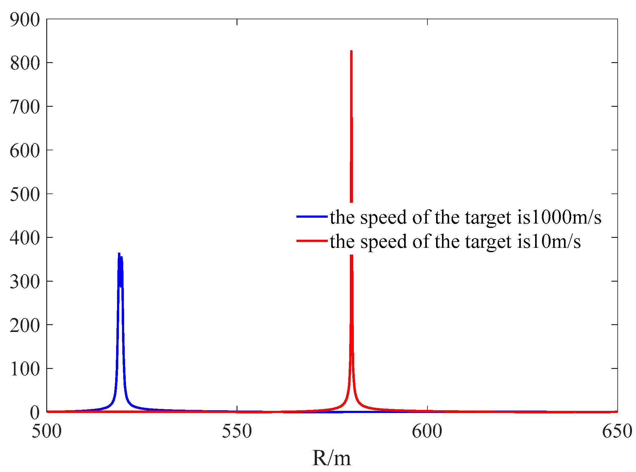
Figure 1. According to the simulation result, the peak value of the iFFT spectrum appears at 580 m when the velocity of the target is 10 m/s. However, the peak value of the iFFT spectrum appears at 520 m when the velocity of the target is 1000 m/s, shifting 60 m away from the true range cell. Besides, its value is almost half of that when the speed is slow. Therefore, motion compensation is a key problem in SFW radar when detecting high-speed targets.
3. Velocity Estimation Approach for SFW Radar by FRFT
From section 2, it can be concluded that the digital beat signal of the SFW radar is a chirp signal whose chirp rate is calculated as
when encountering a moving target. Therefore, the FrFT is considered to be used to estimate the velocity of the target. The block diagram of the velocity estimation approach proposed for SFW radar in this paper is shown in
Figure 2. It takes advantage of the aggregation of the chirp signal in fractional Fourier domain with a specific transform order and estimates the velocity of the targets by searching for the optimal order. After velocity estimation, motion compensation and the iFFT is performed on the beat signal to ultimately obtain the actual range of the target. This approach translates the problem of velocity estimation into peak search of the FrFT in frequency chirp-rate jointly plane. However, the computation complexity of a planar search is high. Therefore, we adopted the GSS algorithm for the peak search in chirp rate domain to reduce the computational complexity of the proposed approach.
3.1. The FrFT Spectrum of the Beat Signal at Optimal Order
For the convenience of analysis, we first consider the case that there is only one ideal point target
in the observation scene of the SFW radar. Then, the FrFT of the beat signal can be denoted as:
In (4),
is the FrFT Kernel, which can be expressed as
represents the transformation order of the FrFT,
represents the transformation gain of the FrFT and
represents a unit impulse function. Shown in
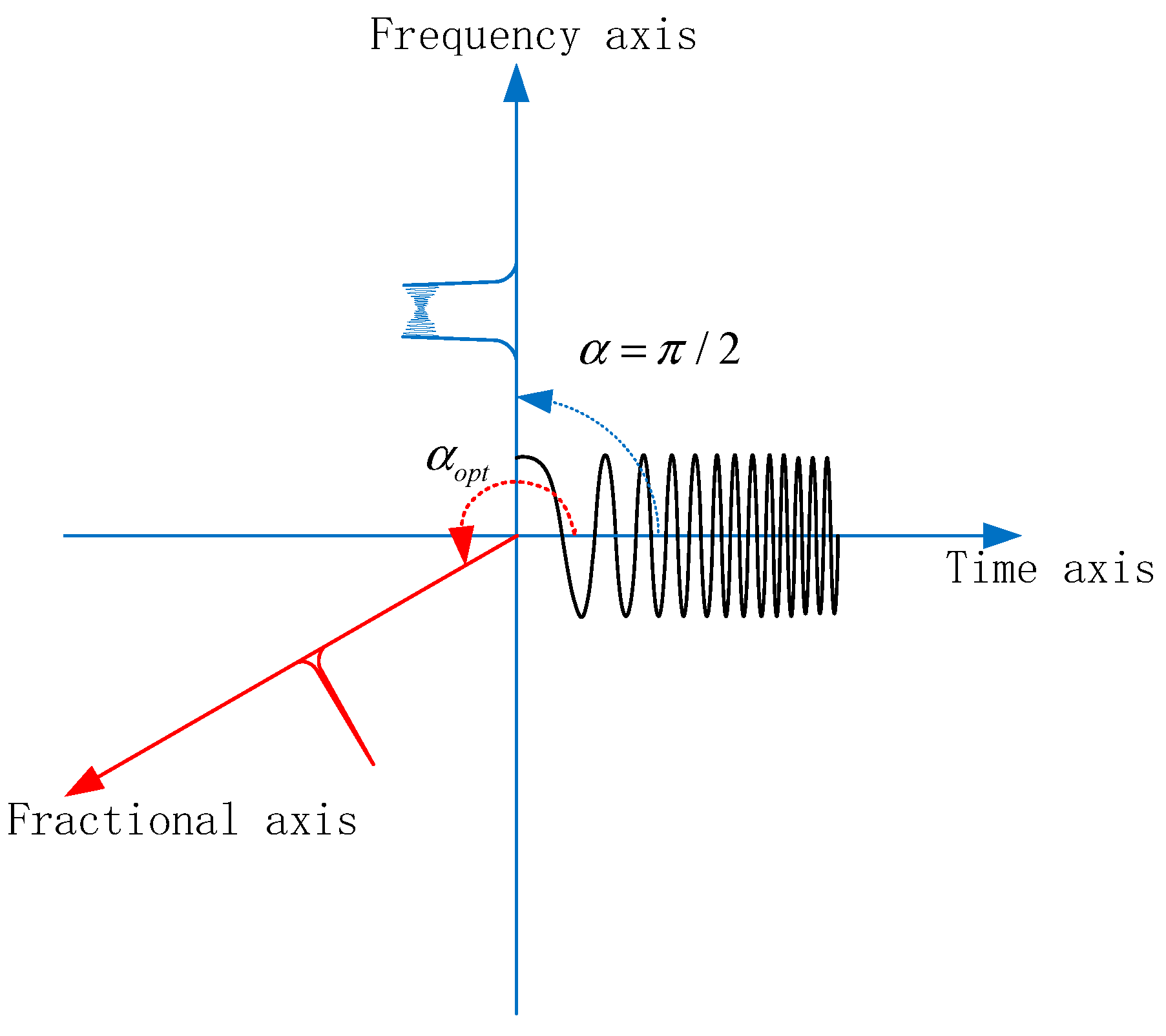
Figure 3, the FrFT can be considered as a rotation of the time frequency plane with the angle
. When
, the FrFT returns to traditional Fourier transform. When
, the chirp signal would exhibit a delta function in the FrFT domain.
According to the property of FrFT, the optimal order of the FrFT in (4) is determined by
and the FrFT spectrum of the beat signal at
can be finally expressed as
According to (6), the FrFT spectrum of the beat signal exhibits a delta function at the optimal order
. Therefore, the velocity estimation problem can be solved by the optimal order search of the FrFT. Due to the orthogonality of the FrFT matrice, the conclusion that
can be inferred. Therefore, the peak of the FrFT spectrum has the max power at the optimal order. Then, the optimal order search can be realized by max power search of the FrFT spectrum in chirp rate domain. Namely, the problem of optimal order search can be solved by the following optimization problem:
After searching for the optimal order, the velocity estimation of the target can be calculated by
From equation (6), the range information of the target can be obtained with the frequency index of the FrFT spectrum at the optimal order. However, the discrete FrFT algorithm proposed by Ozaktas involves shifting and symmetry of the frequency, resulting in the estimation result of
corresponds to the center frequency of the beat signal rather than the initial frequency of the beat signal. Therefore, the proposed approach in
Figure 2 estimates the range information of the target by motion compensation and iFFT, not the estimation of the initial frequency by FrFT.
3.2. Estimation Accuracy of the Fractional Fourier Transform
In this subsection, the estimation accuracy of the proposed approach is analyzed by the variance of the estimated velocity. According to equation (8), the estimation accuracy of the proposed approach depends on the estimation accuracy of the optimal order (or chirp rate). Given the noiseless case of a beat signal with a single ideal point target,
attains its maximums at (
αop,
uop) in the frequency chirp rate jointly plane. Assuming
is differentiable at its peak, then we can form the following equation.
At this point,
is satisfied. Namely, the estimation result of the optimal order is equal to its true value. However, in practical applications, the beat signal output by the SFW radar is always accompanied by noise of varying intensities. When the noise is present, the FrFT spectrum is perturbed by the noise as
In equation (10),
represents conjugate operation,
is the FrFT spectrum of the noise, and
is the noise carried by beat signal. Usually,
can be ignored because the spectrum of the noise is expanded throughout the entire FrFT domain and is low-powered in comparison to the power of the signal. In this case, equation (9) can be approximately simplified as:
where
is the disturbance of the FrFT spectrum caused by noise. Assuming the disturbances caused by noise in frequency domain and chirp rate domain are
and
respectively, the estimated results can be expressed as
and
. Then, the first-order partial derivative of the FrFT spectral at its peak satisfies
Ignoring the higher-order terms, the first-order Taylor series expansion of equation (11) can be expressed as
Substitute equation (9) into equation (13), and make
,
,
,
,
. Ultimately, equation (13) can be expressed as linear equations
According to equation (14), the following equation can be obtained:
In equation (15), since
is only related to the beat signal itself and has nothing to do with the noise carried by the beat signal, they can be calculated directly
The variance of the optimal order can be calculated by
As can be calculated as (18)
Where
is the power of the noise. The variance of the optimal order can be finally expressed as
Then, the variance of the chirp rate can be calculated as
According to equation (8) and equation (20), the variance of the velocity is calculated as:
The detailed derivation of the
and
is shown in
Appendix A.
4. Fast Estimation of The Chirp-Rate by Golden Section Search (GSS)
According to the principle of the proposed velocity estimation and compensation approach in section 3, its core is the estimation of the chirp rate of the beat signal. However, directly searching for the optimal order of the FrFT need traverse all values from to , which is large computational burden. Therefore, the GSS is introduced in searching for the optimal order to reduce computational complexity and improve the real-time performance of the SFW radar. Moreover, drawing lessons from the match pursuit algorithm, the IGSS algorithm is proposed in the paper to solve the problem of multi-scatterers.
4.1. Searching for optimal order by GSS
Some study has verified that the GSS shows well performance for the chirp rate estimation by FrFT [
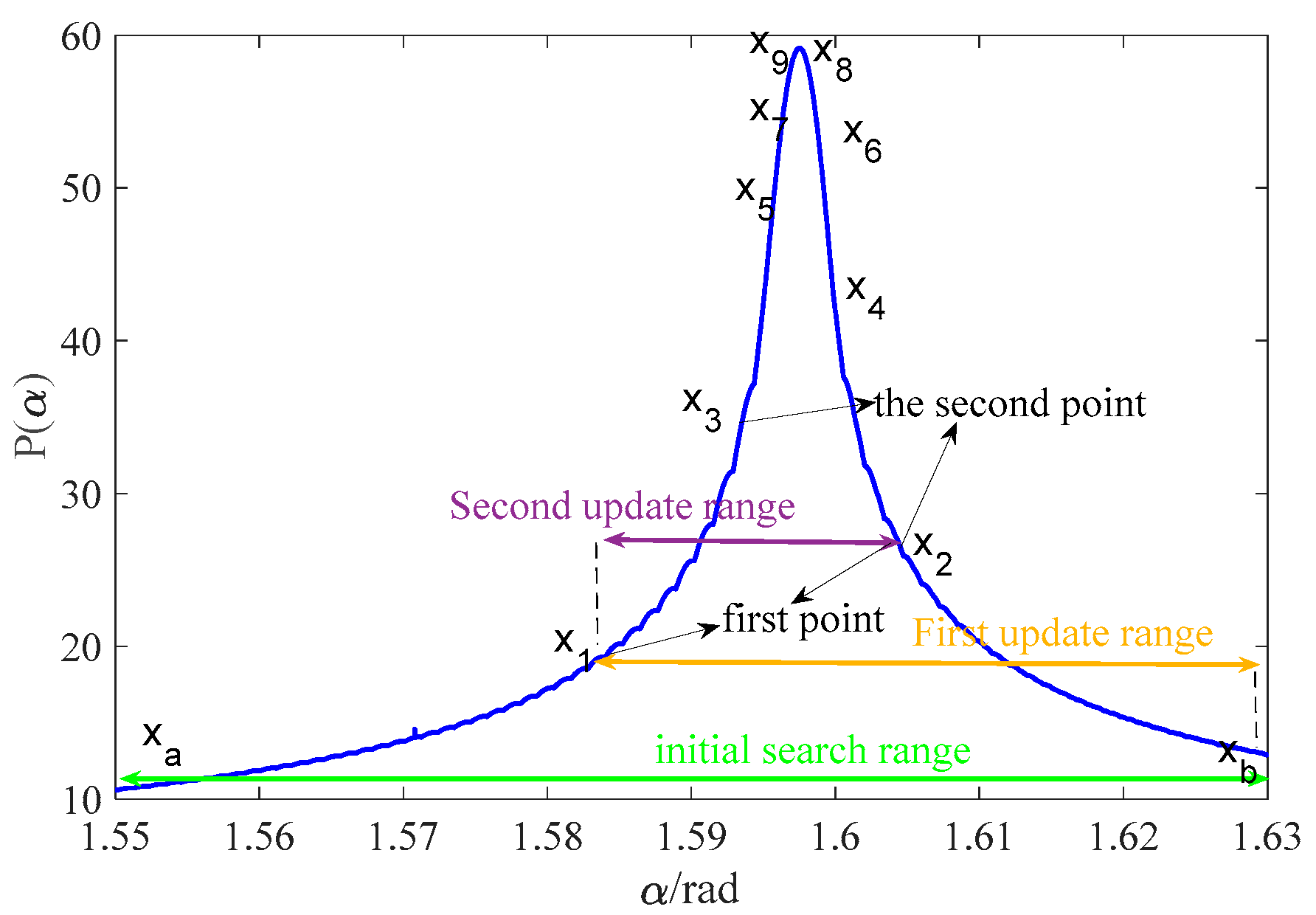
44]. The search process of the GSS is shown in
Figure 4. The GSS starts by pre-determined search scope
which is always initialized based on the prior knowledge. The gold ratio
is used to calculate the order of the first iteration point by
Assuming the objective function that requires searching for the maximum is denoted as
,
and
are calculated to determine the next search scope. If
, the search scope is updated with
, and
is used to replace
for the next judgment process. If
, the search scope is updated with
, and
is used to replace
. By continuously updating the search scope until the condition
is satisfied, the index of the maximum can be determined as
.
|
Algorithm 1: iterative algorithm for estimating the velocity of the target based on GSS. |
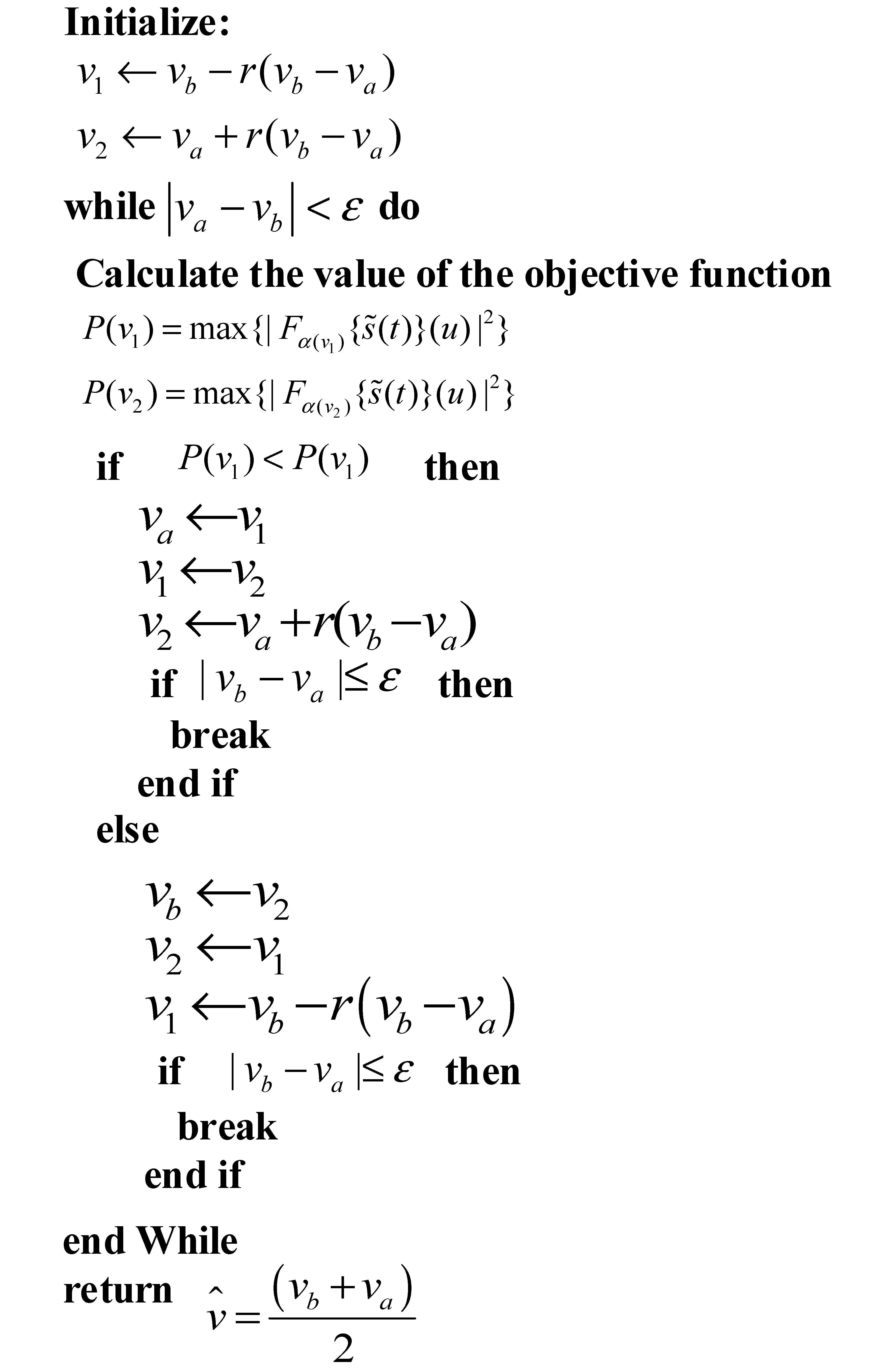 |
In this paper, the objective function can be considered as the peak of the FrFT spectrum with the argument . is a function of . The initial search scope of the GSS can be just preset with the possible speed of the targets. The pseudocode for the search algorithm is provided in Algorithm 1.
4.2. The Iterative GSS for Multi-scatterers
In the scenarios that there are multi-scatterers with different motion states, the beat signal output by the SFW radar is the superposition of several chirp signals with different initial frequencies and chirp rates. It can be expressed as
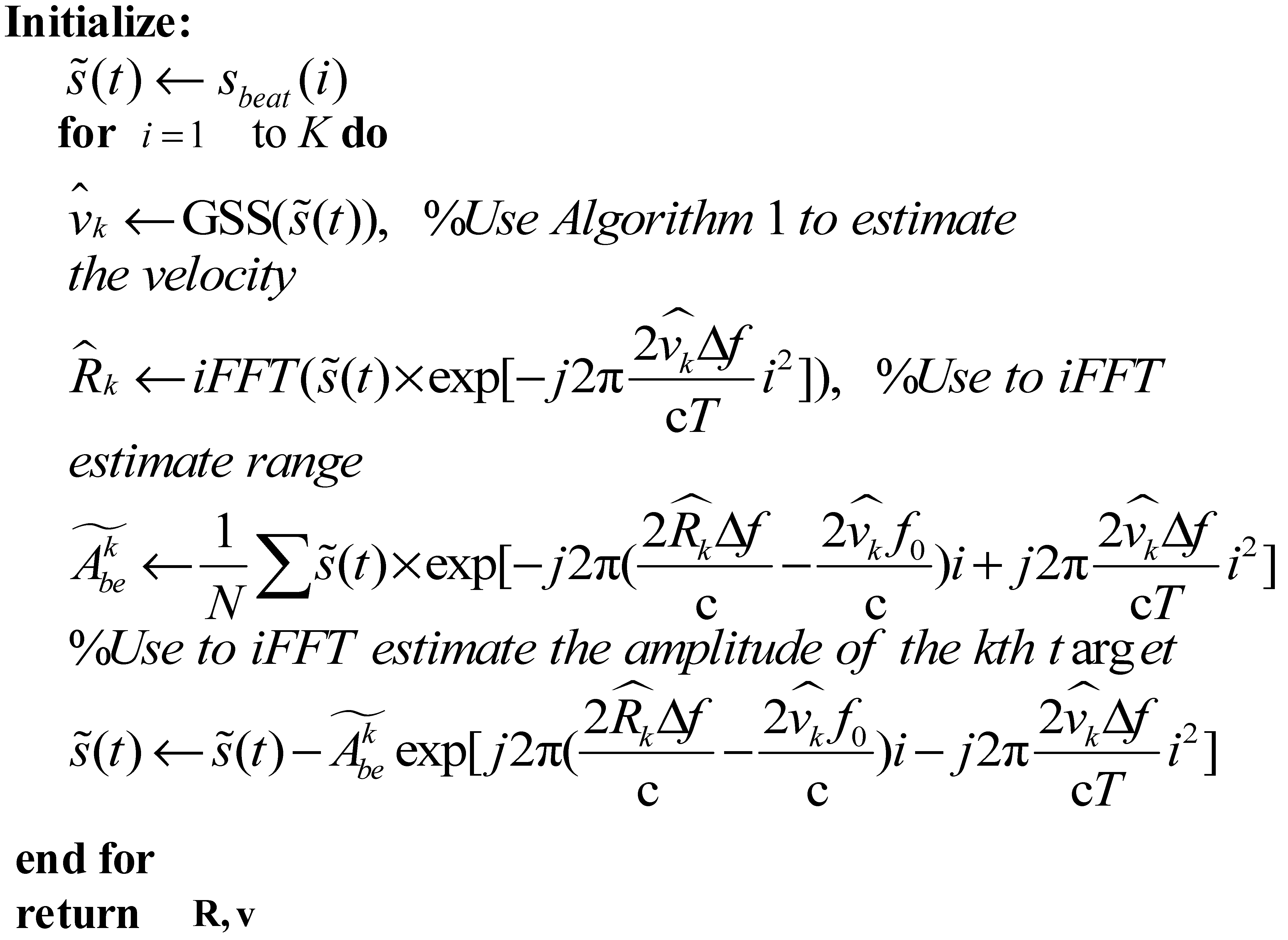
If the GSS mentioned in sub-section 4.1 is used to search for the optimal order, only the beat signal of the brightest scatterer can be detected. Therefore, an iterative GSS, which draws lessons from the match pursuit, is proposed in this sub-section to solve the problem of multi-scatterers. The iterative GSS first estimates the velocity and distance of the brightest scatterer by the ordinary GSS to estimate the velocity of the brightest scatterer. Then, the iFFT is used to calculate the range information of the scatterer after motion compensation.
Finally, the following equation
is used to calculated the complex amplitude
of the beat signal corresponding to the k-th scatterer. After parameter estimation, the estimated parameters are used to reconstruct the beat signal corresponding to the k-th scatterer by
. The reconstructed signal is subtracted from the original beat signal
, and the remained signal
is used as a new beat signal to estimate the parameters of the other scatterers. This process is repeated until the stopping criteria
or
is satisfied. Here,
is a preset constant decided by the power of the noise,
is the index of iterations, and
is the total number of iterations. The pseudocode for the IGSS algorithm is provided in Algorithm 2.
|
Algorithm 2: Proposed Iterative GSS for Multi-scatterers. |
 |
4.3. Computational Cost of the IGSS
The computational cost of the proposed IGSS is decided by the number of iterations and the computational cost of the digital FrFT jointly. The fast digital FrFT proposed by Ozaktas et al includes interpolation, modulation, convolution. The core of this algorithm is the convolution of the chirp signal with the fractional kernel function, which is accelerated by the FFT. The total computational cost of the fast digital FrFT is
In GSS, the loop stops when
. According to [
45], the number of iterations required by GSS is
Where
is the rounding function. According to (26), the number of iterations is mainly decided by the selected
. Therefore, an appropriate value of
should be selected to decrease the total iterations based on the application. In (21), the theoretical variance of the velocity estimated by FrFT is given. To make the GSS converge and achieve this accuracy, the selected
should satisfies that
reaches an order of
. To make the calculation simply, a convenient value of
can be selected as
With the
selected by (27), the total number of iterations can be calculated as
Therefore, the computational complexity of the entire algorithm in the scenario with single scatter is approximately
and the computational complexity of the entire algorithm in the scenario with K scatters is approximately
The computational costs of various motion compensation approaches are shown in
Table 1. When compared to other approaches, the IGSS method undeniably offers an attractive computational cost.
5. Simulation Results
Extensive computer simulations have been conducted to verify the performance of the proposed approach. For the estimation accuracy of the velocity, 2000 times Monte Carlo simulations were conducted for each value of SNR. The standard deviation of the velocity has been calculated by
The SFW radar used in the simulation was a continuous wave radar, and the simulation parameters are shown in
Table 2.
5.1. Mono-scatterer Case
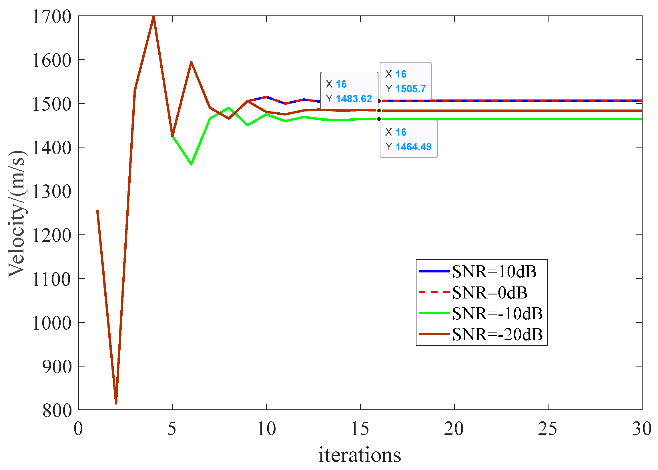
The process of the GSS with a single scatterer at a speed of 1500m/s is shown in
Figure 5. It can be concluded that the GSS gradually converges after 15 iterations under various SNR conditions. When SNR>0 dB, the estimation error of velocity after convergence is approximately 5.48 m/s; When SNR=-10 dB, the estimation error of velocity after convergence increases to 16.45 m/s. Namely, the estimation error of the GSS increases with the deterioration of SNR.
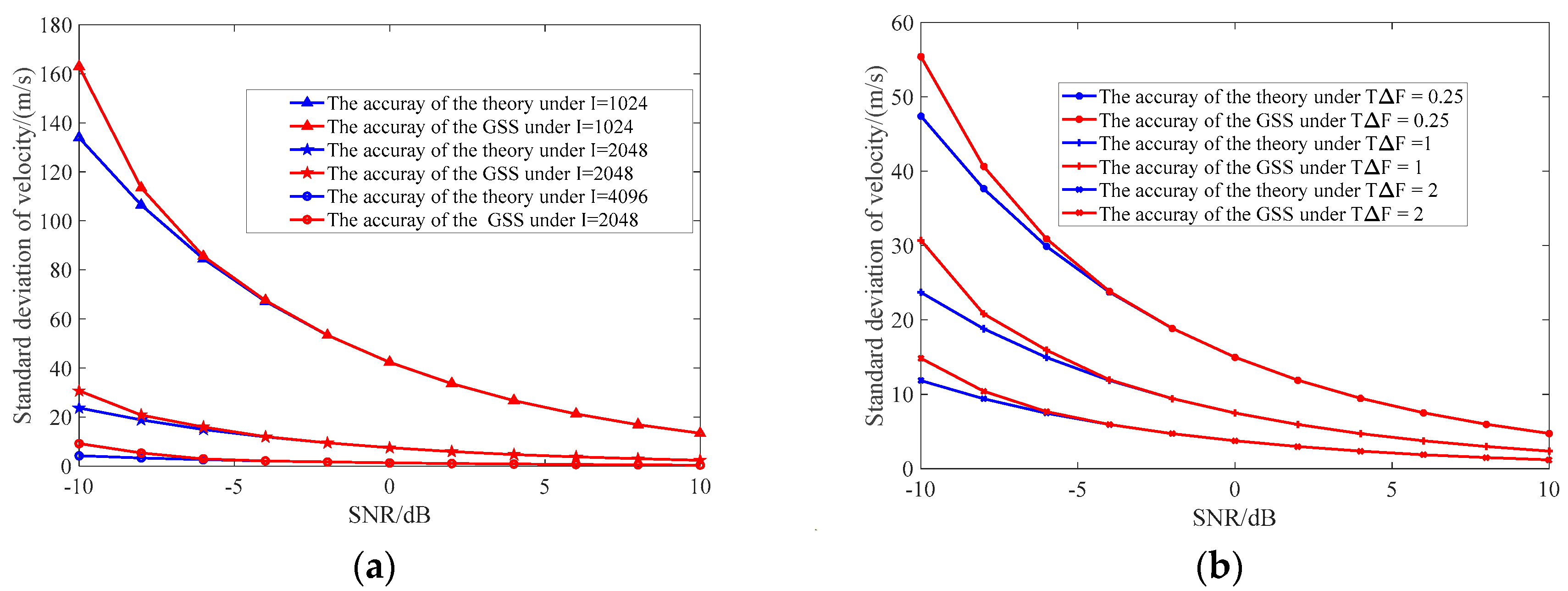
To give a detailed insight of the GSS, the standard deviation of the velocity calculated by equations (17) and (24) with different step points and stepped time-bandwidth products under SNR values ranging from -10 dB to 10 dB are shown in
Figure 6. It can be concluded that the accuracy of the velocity is inversely proportional to both the number of step points
I and the stepped time-bandwidth product. Therefore, we can improve the estimation accuracy of the GSS by increasing the number of steps, the dwell time of the stepped-frequency and the step bandwidth of the transmitting waveform. Besides, the figure makes it clear that the accuracy of the proposed GSS approach closely approximates the that of the theoretical value obtained from (17).
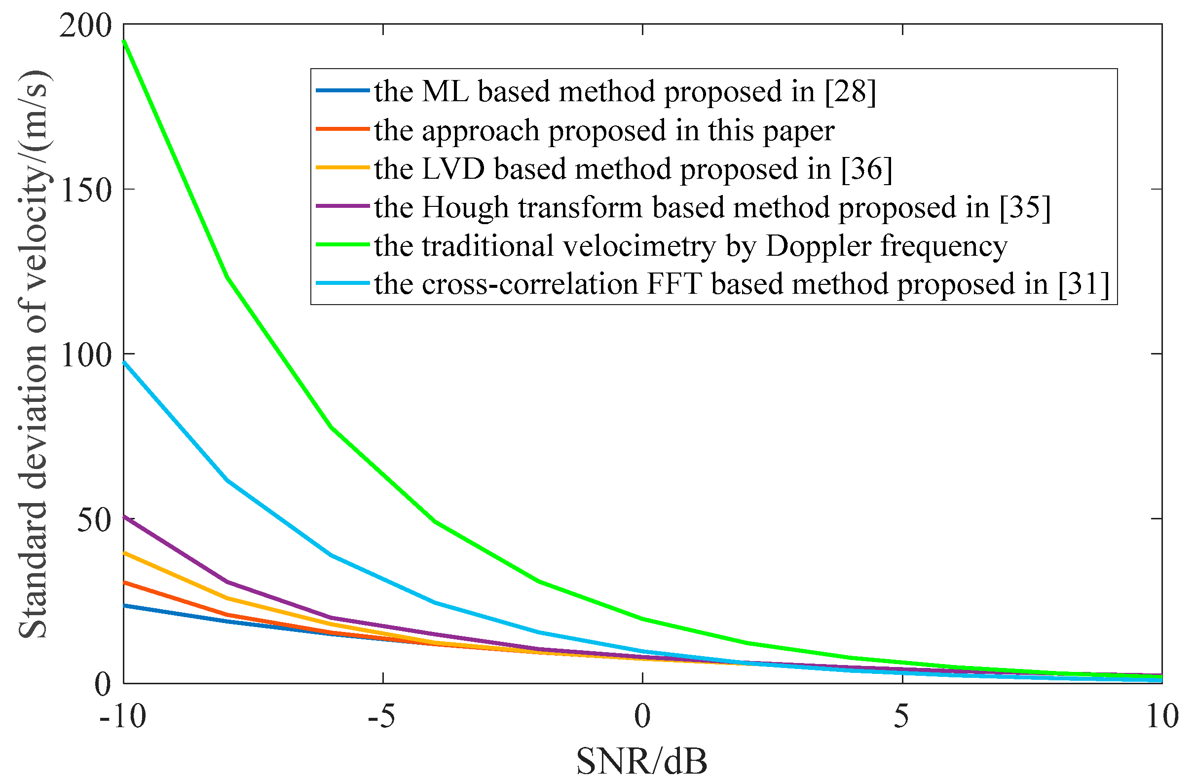
The comparison of the proposed approach with several different methods is shown in
Figure 6. The methods, we selected for comparison include traditional velocimetry by Doppler frequency (without stepped frequency technology), the LVD-based methods [
36], the Hough transform-based method [
35], the ML-based method [
28], and the cross-correlation FFT-based method [
30]. The parameter of the radar is according to table Ⅱ (the step bandwidth of the traditional velocimetry is set to zero). From
Figure 7, the proposed GSS approach has comparable performance to the ML-based method, and is superior to other methods.
5.2. Multi-scatterers Case
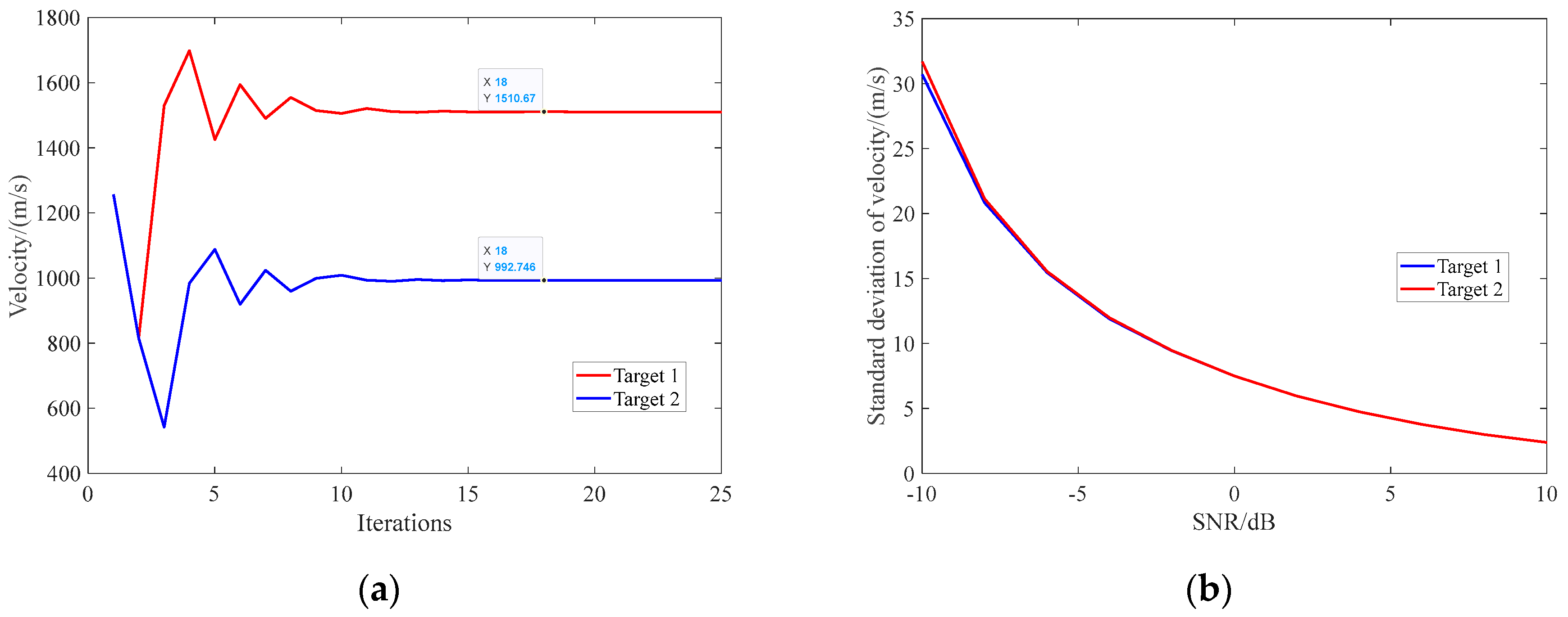
When there are two point-targets with velocities of 1500 m/s and 1000 m/s in the observation scenario, the convergence of the iterative GSS under SNR= 0dB condition is shown in
Figure 8. It can be seen that the iterative GSS converges after 15 iterations when there are two point-targets with different velocities. The estimation accuracy of the iterative GSS under different SNR is shown in
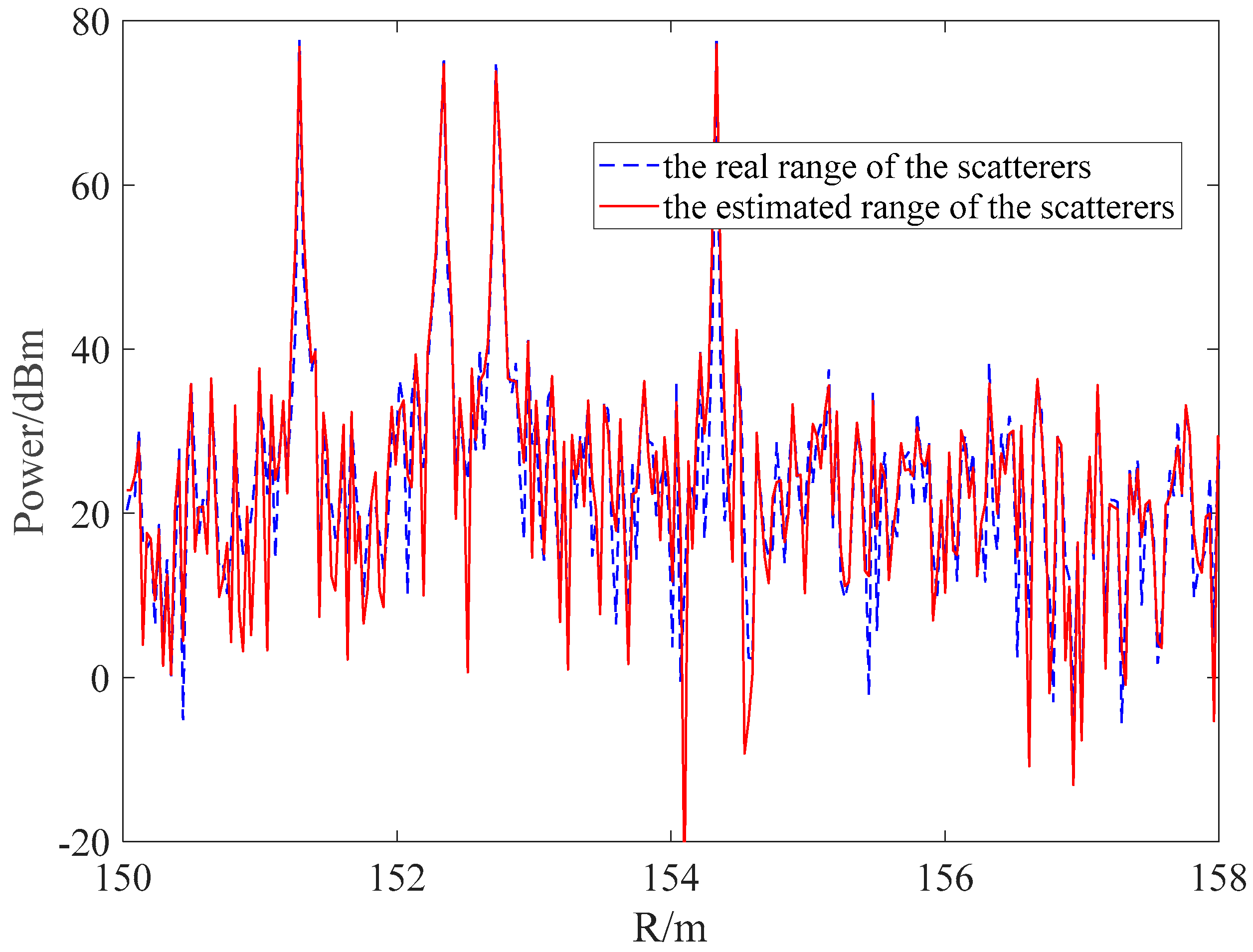
Figure 8(b). The estimation accuracy is almost equivalent to that of a single point-target. However, the estimation accuracy of target 2 is a slightly lower than that of target 1. This is because the target 1 is firstly estimated and compensated, and its residual influenced the estimation of target 2 by deteriorating the SNR. The HRRP image of a four-scatterers target with the velocity of 1000m/s obtained by iterative GSS is shown in
Figure 9. The real range of the scatterers was obtained by iFFT with a velocity of 1000m/s, while the estimated range of the scatterers was obtained by the iterative GSS. From the results of the proposed iterative GSS, it can obtain the HRRP image of multi-scatterer targets.
The simulation model used in this paper is a SFW radar, whose detection range is limited by sampling rate (dwell time of stepped-frequency) of its transmitting waveform. In practice, we can combine the SFW with a chirp waveform (namely stepped-frequency chirp waveform radar) to improve the detection range and the SNR of the Doppler signal. The proposed iterative GSS is also suitable for the stepped-frequency chirp waveform radar with additional pulse compression before the velocity estimation. Here, we don’t provide the simulation of the stepped-frequency chirp waveform radar for its high similarity with SFW radar.
6. Conclusions
In this paper, we have put forward an accelerated method for estimating the velocity of moving targets using Stepped Frequency Waveform (SFW) radar, which harnesses the fractional Fourier transform (FrFT) complemented by an iterative golden section search (GSS) for the optimal FrFT order determination. Through a series of simulations, we have substantiated the robustness of our proposed methodology. The simulation outcomes indicate a marked improvement in velocity estimation precision over conventional FFT-based techniques. Moreover, our method approaches the estimative acuity of Maximum Likelihood (ML) methods, renowned for their supreme accuracy within Gaussian settings. Crucially, our approach achieves this while incurring a significantly lower computational cost, thereby presenting a more viable option for integration into radar systems. The iterative GSS algorithm we developed proves to be effective for scenarios involving multiple scatterers and succeeds in delivering a High Range Resolution Profile (HRRP) image for targets with up to four scatterers.
Author Contributions
Author Contributions: Conceptualization, P.B. and Q.C.; methodology , B.P. and Q.C.; soft-ware, Q.Z. and J.Z.; validation, C.W. formal analysis, B.P. and C.Q.; investigation, B.P.; resources, Q.C.; data curation, Q.C.; writing—original draft preparation, B.P..; writing—review and editing, Q.C.; supervision, R. H. Z; project administration, R. H. Z. All authors have read and agreed to the published version of the manuscript.
Data Availability Statement
The data are available from the corresponding author upon reasonable request.
Acknowledgments
In this section, you can acknowledge any support given which is not covered by the author contribution or funding sections. This may include administrative and technical support, or donations in kind (e.g., materials used for experiments).
Conflicts of Interest
The authors declare no conflict of interest.
Appendix A. derivation of the
For the convenience of analysis, the amplitude of the beat signal is defined as
, the initial phase of the beat signal is defined as
, the initial frequency of the beat signal is defined as
and the chirp rate of the beat signal is defined as
. Then the beat signal can be expressed as
and its corresponding results after FrFT can be expressed as
The FrFT spectrum introduced by the noise perturbation which can be expressed as
Then, the first derivative of (A3) with respect to
can be expressed as
Therefore,
can be expressed as
According to the definition in (10), we can obtained
Subsituting (A6)-(A9) into (A5), we can obtain that
With the similar calculation process,
can be obtained by
and
can be obtained by
Subsituting the definition of the and into (A10)~(A12), the final results in (18) can be formed.
References
- Mun, Kok Leog. Stepped Frequency Imaging Radar Simulation. AD-A379137, Naval Postgraduate School, 2000.
- Zou, Y.Q.; Gao, X.Z.; Li, X.; Liu, Y.X. A Matrix Pencil Algorithm Based Multiband Iterative Fusion Imaging Method. Sci. Rep. 2016, 6, 19440. [Google Scholar] [CrossRef] [PubMed]
- He, F.; Xu, X. High-Resolution Imaging Based on Coherent Processing for Distributed Multi-Band Radar Data. Progress in Electromagnetics Research-pier 2013. [CrossRef]
- Chen, H.-Y.; Liu, Y.-X.; Jiang, W.-D.; Guo, G.-R. A New Approach for Synthesizing the Range Profile of Moving Targets via Stepped-Frequency Waveforms. IEEE Geosci. Remote Sens. Lett. 2006, 3, 406–409. [Google Scholar] [CrossRef]
- He, S.; Zhang, W.; Guo, G. High Range Resolution MMW Radar Target Recognition Approaches with Application. In Proceedings of the Proceedings of the IEEE 1996 National Aerospace and Electronics Conference NAECON ; 1996; pp. 192–195. [Google Scholar]
- Zhang R, Xu L, Yu Z, et al. Deep-IRTarget: An automatic target detector in infrared imagery using dual-domain feature extraction and allocation. IEEE Trans. Multimed. 2021, 24, 1735–1749. [Google Scholar]
- Zhang Q, Ge L, Zhang R, et al. Deep-learning-based burned area mapping using the synergy of Sentinel-1&2 data. Remote Sens. Environ. 2021, 264, 112575. [Google Scholar]
- Zhang R, Yang S, Zhang Q, et al. Graph-based few-shot learning with transformed feature propagation and optimal class allocation. Neurocomputing 2022, 470, 247–256. [Google Scholar] [CrossRef]
- D. L. Mensa, High resolution radar cross section imaging, 2. rev. In The Artech House radar library; Artech House: Boston, MA, USA, 1991. [Google Scholar]
- Yang, T.; Dong, Q.; Huang, Q. A Novel Echo-Based Error Estimation and Ripple Elimination Method for Stepped Frequency Chirp SAR Signal. IEEE Access 2019, 7, 182839–182845. [Google Scholar] [CrossRef]
- Phelan, B.R.; Ranney, K.I.; Gallagher, K.A.; Clark, J.T.; Sherbondy, K.D.; Narayanan, R.M. Design of Ultrawideband Stepped-Frequency Radar for Imaging of Obscured Targets. IEEE Sens. J. 2017, 17, 4435–4446. [Google Scholar] [CrossRef]
- Paulose, Abraham Thomas. High Radar Range Resolution with the Step Frequency Waveform. Theory of Computing Systems \/ Mathematical Systems Theory 1994, 7.
- Schweizer, B.; Knill, C.; Schindler, D.; Waldschmidt, C. Stepped-Carrier OFDM-Radar Processing Scheme to Retrieve High-Resolution Range-Velocity Profile at Low Sampling Rate. IEEE Trans. Microw. Theory Techn. 2018, 66, 1610–1618. [Google Scholar] [CrossRef]
- Tian, T.-T.; Liu, L.; Xu, M. New estimation method of target’s radial velocity for stepped-frequency radar. J. Beijing Univ. Aeronaut. Astronaut. 2008, 34, 673. [Google Scholar]
- Axelsson, S.R.J. Analysis of Random Step Frequency Radar and Comparison With Experiments. IEEE Trans. Geosci. Remote Sens. 2007, 45, 890–904. [Google Scholar] [CrossRef]
- Mao, Z.; Wei, Y. Interpulse-frequency-agile and Intrapulse-phase-coded Waveform Optimisation for Extend-range Correlation Sidelobe Suppression. IET Radar Sonar Navig. 2017, 11, 1530–1539. [Google Scholar] [CrossRef]
- Liao, Z.; Lu, D.; Hu, J.; Zhang, J. A Novel Range Profile Synthesis Method for Random Hopping Frequency Radar. In Proceedings of the 2016 IEEE International Conference on Digital Signal Processing (DSP); IEEE: Beijing, China, 2016; pp. 79–83. [Google Scholar]
- Wang, X.; Wang, R.; Deng, Y.; Wang, P.; Li, N.; Yu, W.; Wang, W. Precise Calibration of Channel Imbalance for Very High Resolution SAR With Stepped Frequency. IEEE Trans. Geosci. Remote Sens. 2017, 55, 4252–4261. [Google Scholar] [CrossRef]
- Liu, Y.; Huang, T.; Meng, H.; Wang, X. Fundamental Limits of HRR Profiling and Velocity Compensation for Stepped-Frequency Waveforms. IEEE Trans. Signal Process. 2014, 62, 4490–4504. [Google Scholar] [CrossRef]
- Xia, G.; Su, H.; Huang, P. Velocity Compensation Methods for LPRF Modulated Frequency Stepped-Frequency (MFSF) Radar. J. Syst. Eng. Electron. 2010, 21, 746–751. [Google Scholar] [CrossRef]
- Liu, Y.; Meng, H.; Li, G.; Wang, X. Velocity Estimation and Range Shift Compensation for High Range Resolution Profiling in Stepped-Frequency Radar. IEEE Geosci. Remote Sens. Lett. 2010, 7, 791–795. [Google Scholar] [CrossRef]
- Shao, S.; Zhang, L.; Liu, H. High-Resolution ISAR Imaging and Motion Compensation With 2-D Joint Sparse Reconstruction. IEEE Trans. Geosci. Remote Sens. 2020, 58, 6791–6811. [Google Scholar] [CrossRef]
- Sen, W.; Qinglong, B.; Zengping, C. Range Migration Compensation for Moving Targets in Chirp Radars with Stepped Frequency. J. Eng. 2019, 2019, 5553–5557. [Google Scholar] [CrossRef]
- Liao, Z.; Hu, J.; Lu, D.; Zhang, J. Motion Analysis and Compensation Method for Random Stepped Frequency Radar Using the Pseudorandom Code. IEEE Access 2018, 6, 57643–57654. [Google Scholar] [CrossRef]
- Zhang, Y.; Yeh, C.; Li, Z.; Lu, Y.; Chen, X. Design and Processing Method for Doppler-Tolerant Stepped-Frequency Waveform Using Staggered PRF. Sensors 2021, 21, 6673. [Google Scholar] [CrossRef] [PubMed]
- Yang, J.; Qiu, Z.; Li, X.; Zhuang, Z. Analysis and Processing of the Chaotic-based Random Stepped Frequency Signal. J. Natl. Univ. Def. Technol. 2012, 34, 163–169. [Google Scholar]
- Zeng, T.; Chang, S.; Fan, H. Liu, Q. Design and Processing of a Novel Chaos-Based Stepped Frequency Synthesized Wideband Radar Signal. Sensors 2018, 18, 4–985. [Google Scholar] [CrossRef] [PubMed]
- Aubry, A.; Carotenuto, V.; De Maio, A.; Pallotta, L. High Range Resolution Profile Estimation via a Cognitive Stepped Frequency Technique. IEEE Trans. Aerosp. Electron. Syst. 2019, 55, 444–458. [Google Scholar] [CrossRef]
- Wei, S.; Zhang, L.; Ma, H.; Liu, H. Sparse Frequency Waveform Optimization for High-Resolution ISAR Imaging. IEEE Trans. Geosci. Remote Sens. 2020, 58, 546–566. [Google Scholar] [CrossRef]
- Feng Zhu; Qun Zhang; Qiang Lei; Ying Luo Reconstruction of Moving Target’s HRRP Using Sparse Frequency-Stepped Chirp Signal. IEEE Sens. J. 2011, 11, 2327–2334. [CrossRef]
- Liu, Y.; Meng, H.; Zhang, H.; Wang, X. Motion Compensation of Moving Targets for High Range Resolution Stepped-Frequency Radar. Sensors 2008, 8, 3429–3437. [Google Scholar] [CrossRef] [PubMed]
- Tian, J.; Liu, L.; Xue, M. New estimation method of targets radial velocity for stepped-frequency radar. J. Beijing Univ. Aeronaut. Astronaut. 2008, 34, 673–676. [Google Scholar]
- Qu, L.; Fan, X.; Chen, Z. Motion Compensation Method for Stepped Frequency Radar. In Proceedings of the 2018 2nd IEEE Advanced Information Management, Communicates, Electronic and Automation Control Conference (IMCEC); IEEE: Xi’an, China, 2018; pp. 621–625. [Google Scholar]
- ZLiu, S.Z.h.a.n.g. Estimation of target motion parameter in a stepped frequency pulses radar. Acta Electron. Sin. 2000, 28, 43–46. [Google Scholar]
- Y. Cui, W. Luo, D. Wang. A Motion Compensation Method for Stepped-Frequency Radar Based on Joint Chirp-Fourier Transform. Trans. Beijing Inst. Technol. 2015, 35, 627–633. [Google Scholar] [CrossRef]
- Wu, X.F.; Wang, X.S.; Lu, H.Z. Motion Feature Extraction for Stepped Frequency Radar Based on Hough Transform. IET Radar Sonar Navig. 2010, 4, 17. [Google Scholar] [CrossRef]
- Hao, L.; Xiuming, G. Stepped Frequency RADAR Target Detection Based on the Hough Transform. In Proceedings of the 2011 Cross Strait Quad-Regional Radio Science and Wireless Technology Conference; July 2011; Volume 2, pp. 1078–1081. [Google Scholar]
- Yang, Z. Zong and C. Yu. Maneuvering Target Velocity Estimation Based on Lv's Distribution for LFM Stepped-Frequency Radar Signal. IGARSS 2023-2023 IEEE International Geoscience and Remote Sensing Symposium, Pasadena, CA, USA, 2023; pp. 6137–6140. [CrossRef]
- Lv, G. Bi, C. Wan and M. Xing. Lv's Distribution: Principle Implementation Properties and Performance. IEEE Trans. Signal Process. 2011, 59, 3576–3591. [Google Scholar] [CrossRef]
- Aldimashki and, A. Serbes. Performance of Chirp Parameter Estimation in the Fractional Fourier Domains and an Algorithm for Fast Chirp-Rate Estimation. IEEE Trans. Aerosp. Electron. Syst. 2020, 56, 5–3685. [Google Scholar] [CrossRef]
- Shi, J.; Chen, G.; Zhao, Y.; Tao, R. Synchrosqueezed Fractional Wavelet Transform: A New High-Resolution Time-Frequency Representation. IEEE Trans. Signal Process 2023, 71, 264–278. [Google Scholar] [CrossRef]
- Serbes. On the estimation of LFM signal parameters: Analytical formulation. IEEE Trans. Aerosp. Electron. Syst. 2018, 54, 848–860. [Google Scholar] [CrossRef]
- H. M. Ozaktas, O. Arikan, M. A. Kutay, and G. Bozdagi. Digital computation of the fractional Fourier transform. IEEE Trans. Signal Process 1996, 44, 9–2141. [Google Scholar] [CrossRef]
- Serbes; Aldimashki, O. A fast and accurate chirp rate estimation algorithm based on the fractional Fourier transform. Proc. 25th Eur. Signal Process. Conf.,Kos, Greece; 2017; 17, pp. 1105–1109. [Google Scholar]
- Serbes. On the estimation of LFM signal parameters: Analytical formulation. IEEE Trans. Aerosp. Electron. Syst. 2018, 54, 848–860. [Google Scholar] [CrossRef]
|
Disclaimer/Publisher’s Note: The statements, opinions and data contained in all publications are solely those of the individual author(s) and contributor(s) and not of MDPI and/or the editor(s). MDPI and/or the editor(s) disclaim responsibility for any injury to people or property resulting from any ideas, methods, instructions or products referred to in the content. |
© 2024 by the authors. Licensee MDPI, Basel, Switzerland. This article is an open access article distributed under the terms and conditions of the Creative Commons Attribution (CC BY) license (https://creativecommons.org/licenses/by/4.0/).


