Preprint
Article

Model Test Study on Rock Rolling Characteristics

Altmetrics

Downloads

70

Views

25

Comments

0

A peer-reviewed article of this preprint also exists.

Submitted:

25 December 2023

Posted:

26 December 2023

You are already at the latest version

Alerts
Abstract
In order to study the influence of falling rock shape on its rolling characteristics and realize the optimization of falling rock protection design, the following research was carried out. Design model experiments to explore the rolling characteristics of different shapes of rockfalls. Based on the experimental results, it was found that the slenderness ratio, center of gravity, and rotational inertia of the rockfalls can affect their rolling characteristics, leading to swaying and changing the rolling axis during the rolling process, thereby affecting their rolling speed. On this basis, the formation mechanism of rolling resistance is analyzed, and the main cause of energy loss is the rolling resistance arm formed with the rolling surface during rockfall rolling, and a shape parameter to quantify the rolling resistance is proposed. The parameters are substituted into the kinematic formula, in which the influence of the rockfall shape, slope and slope roughness on the rolling speed is considered. Combined with the offset and initial position of the rockfall, the formula can be used to calculate the rolling speed and impact energy in the rolling region and any position in the region. The calculation formula was validated using model experimental data, and the results showed that the error between the experimental and calculated values was small. The error was corrected based on the experimental data. After on-site testing and verification, it can provide reference for the management of rockfall disasters.
Keywords: 
Subject: Engineering  -   Civil Engineering

1. Introduction

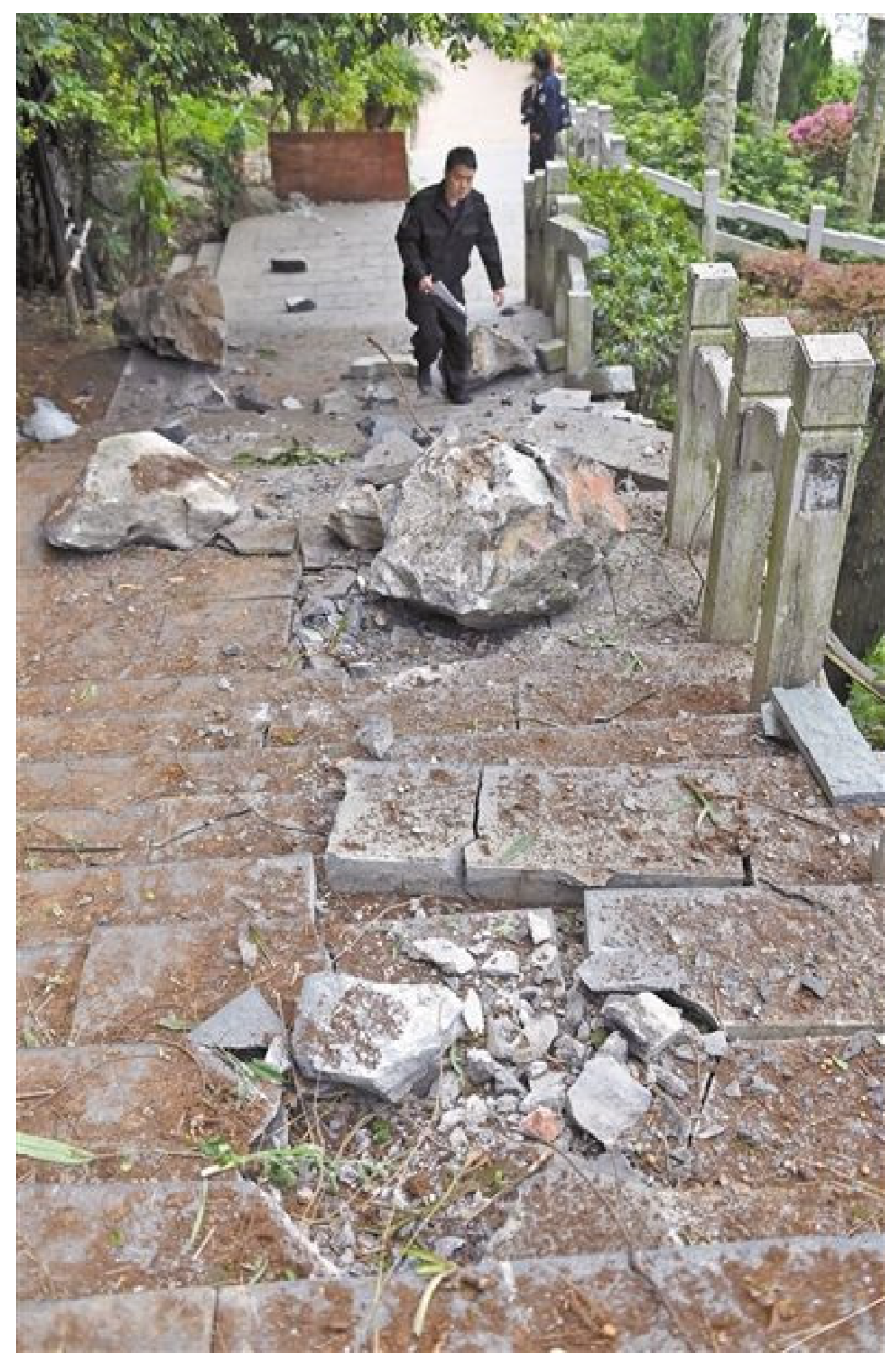
Rocks involved in collapses and landslides exhibit characteristics such as high destructiveness, suddenness, scattered distribution, and complex and unpredictable trajectories [1,2]. They represent a primary geological hazard in the mountainous regions of China. In 2022 alone, China witnessed 1,366 incidents of rockfall disasters, constituting 24.14% of the total geological disasters in the country and posing a severe threat to the safety of people's lives and property. Figure 1 and Figure 2 illustrate the devastation caused by rockfalls.
In the design of protection against rockfall, it is necessary to calculate the characteristics of rockfall movement accurately, and the rockfall shape is very important to determine the rotation and collision behavior, it is the key factor of energy consumption and trajectory change in rolling process. The different shape of rockfall results in different moments of inertia, which affects the rotation behavior of rockfall in contact with slope [3]. Such dynamics play a decisive role in determining the extent of hazard and design of protection against rockfall. The data of rockfall position, velocity, rotation, energy and impact force are used to determine the influence range and hazard degree of rockfall, therefore, the optimized design of rock falling protection can be realized.
The current research methods related to the characteristics of rockfall movement mainly include theoretical derivation [4], model experiments [5,8], numerical simulations [9,12], and mathematical probability models for data analysis and statistics of historical rock collapse events [13,15]. Theoretical derivation is usually based on kinematic principles and contact mechanics to derive the trajectory of a falling rock. Among them, Zhou [16] derived formulas for calculating motion characteristics such as rockfall velocity and displacement. Cui et al. [17] established a model for oblique throwing and impact of falling rocks, which can calculate the movement distance and impact force of rockfalls. Yang et al. [18] considered the influence of the rotational inertia of rockfalls and divided the motion of rockfalls into five stages, and provided calculation formulas for each stage. On the basis of considering geometric similarity, physical similarity, and material similarity, indoor model experiments will scale down the actual site in the model device. Among them, Oda et al. [19] pointed out based on indoor test results that rolling resistance not only comes from contact behavior during the rolling process, but also from the shape of rockfalls. Ai et al. [20] believed that shape effect is an important source of rolling resistance for rockfalls; Gao et al. [21] clarified that the sphericity of rockfalls is a key shape parameter that affects rolling characteristics based on model test results; Giani et al. [22] pointed out that the rotational speed of a block is a function of its rotational inertia on the cross-section where it moves. Ushiro et al. [23] found through experiments that the rolling distance and velocity of rockfalls are positively correlated with their volume. Cui et al. [24] used the ratio of rock block volume to its minimum circumscribed circle volume as a parameter to describe its shape characteristics, and proposed a rolling speed calculation model including the shape parameter of rockfall based on indoor experimental data. Lü et al. [25] studied the fracture mechanism of rock blocks and pointed out that the degree of fracture is closely related to the mechanical properties of the rockfall, but not significantly related to the size of the rockfall. Therefore, for rockfalls with poor mechanical properties in karst areas [26,27], the calculation should consider the occurrence of fractures during the rolling process. Numerical simulation can be divided into rockfall software simulation and code for developing rock fall simulation. Leine et al. [28] proposed a rock collapse trajectory analysis model based on the framework of multi body dynamics and non smooth contact dynamics, which can simulate rock collapse and rockfall events of any shape of rock blocks on different characteristic slopes in full 3D. The trajectory analysis model proposed by Yan et al. [29] can simulate rockfalls with different sphericity and convexity. Bourrier et al. [30] calibrated existing 2D rock collapse prediction models and achieved accurate prediction of the farthest impact range of rockfall. Zhang et al. [31] imported a three-dimensional geological model into simulation software (RAMMS) to obtain the motion trajectory of rockfalls. Xu et al. [32] used the Energy Tracking Method (ETM) to study the impact of rock fragmentation on its motion trajectory and pointed out that the fragmentation process is accompanied by energy loss, leading to a decrease in rolling speed.
To sum up, the shape and size of rockfall are key factors affecting its rolling speed and determine its moment of inertia, which in turn affects its rotation behavior in the air and contact with the ground. The rolling resistance of rockfall comes from the mutual contact with the slope during the rolling process, the contact between different shapes of rockfall and the slope is also different. Therefore, the shape of rockfall determines the rolling resistance what need to overcome during the rolling process. It can be seen that it is necessary to study and quantify the relationship between rockfall shape and rolling resistance, to supplement the quantitative parameters of the influence of rockfall shape on rolling velocity on the basis of the existing calculation formula.
As can be seen from Table 1, it is difficult to establish an ideal calculation model with a single research method when considering the influence of the shape of falling rock on its rolling speed. Therefore, in the follow-up research, model test research and theoretical analysis can be combined to obtain the movement of different shapes of fallen rocks on the slope. Finally, according to the test results, the influence mechanism of rockfall shape on its rolling characteristics is analyzed, and on this basis, the influence of other factors is combined to establish a calculation model.
In order to explore the influence of shape on the movement characteristics of falling rock, the shape of falling rock that is prone to rockfall disaster is selected for model tests. Release test blocks of different shapes from slopes of different heights and slopes, and observe the rolling characteristics and changes in rolling speed of each test block at different release heights, slope roughness, and slopes. Based on experiment results, the relationship between rock falling shape and rolling resistance is analyzed, and the shape parameters which can quantify the rolling resistance of rock falling are proposed. By introducing parameters into the kinematic formula and considering the influence of specimen shape, size, release height, slope, and slope roughness, a formula for calculating the rolling speed and energy of rockfall is derived. Finally, the accuracy and applicability of the above formula were verified using the data obtained from model experiments. By combining the characteristics of the site with the shape of rockfalls, the impact range of falling rock rolling can be inferred, providing reference for the prevention and control of rockfall disasters.

2. Experiment Introduction

2.1. Experiment Apparatus

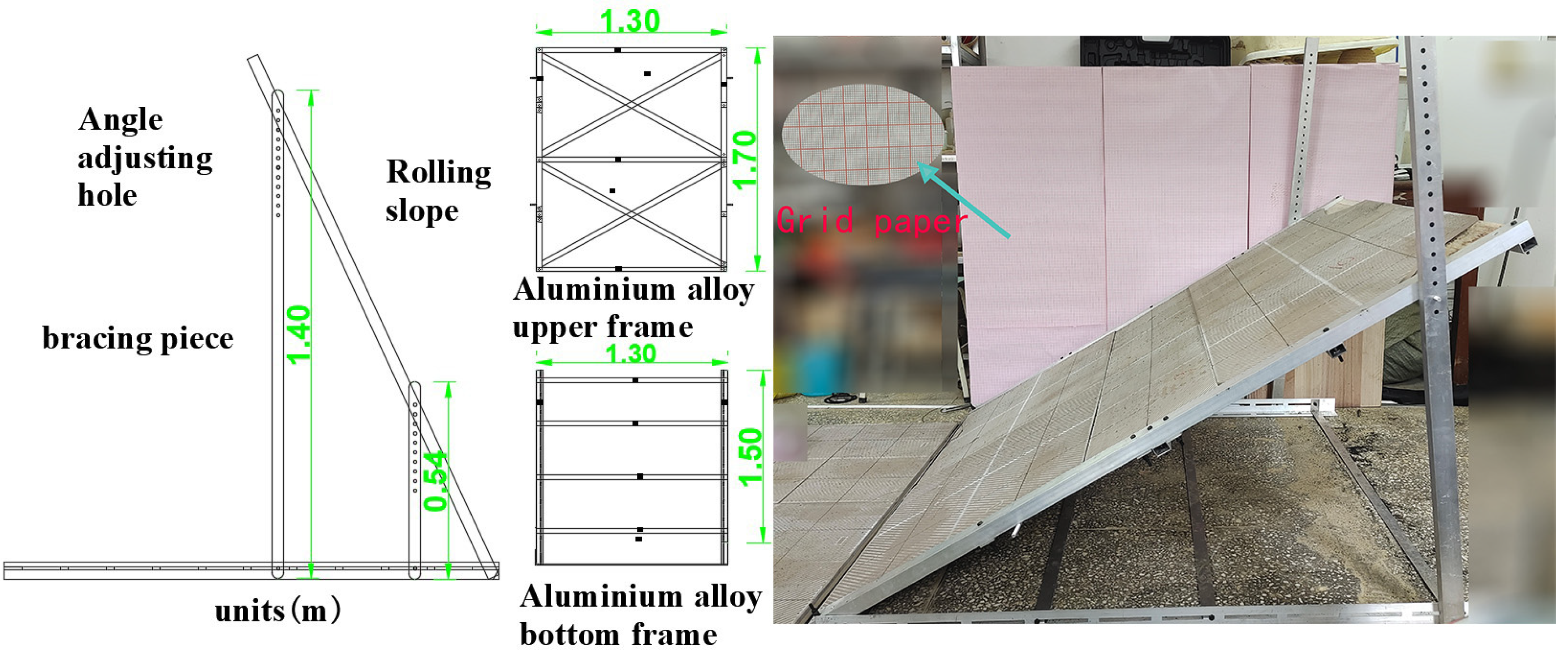
To investigate the rolling characteristics of rocks with varying shapes and sizes on slopes, an experimental model apparatus made of aluminum alloy was designed, as depicted in Figure 3.
The experimental device consists of two symmetrically arranged support rods, an upper frame for placing the rolling surface material of the test block, and a bottom fixed frame for maintaining the stability of the device. The upper frame is composed of aluminum alloy square tubes and connectors; The bottom frame is connected by four aluminum alloy connecting components of the same length and longitudinally arranged, with horizontally placed angle steel, using bolts. Preliminary adjustment of the angle between the upper and lower frames by reserving holes for bolts on the support rod; After approaching the required slope for the test, use the reserved interface of the angle steel placed horizontally at the bottom to fine tune the slope and fix the support rod on the reserved angle steel interface.
The rolling slope size is 1.3m × 1.7m, single or composite slope materials can be placed according to experimental requirements. Among them, there are no barriers on both sides of the slope to avoid energy loss caused by collision or friction between the test block and the side walls of the slope during rolling. The slope adjustment range is 25 ° —75 °, which ensures that the slope of the test block is greater than its rolling friction angle when released, allowing the test block placed on the slope to tip under gravity and develop into continuous rolling.
The experimental shooting equipment was a high-speed camera produced by SONY, model AX-700. The frame rate selected for the experiment was 1000 frames /s. Among them, in order to increase the contrast during the rockfall movement and obtain better shooting effect, grid lines are drawn on the slope material as the camera background.

2.2. Experimental Materials

2.2.1. Rock Materials and Shape Parameters

When selecting the shapes of rockfalls for the test, reference was made to the three typical shape features of fallen rocks in mountainous areas that are prone to induce rockfall disasters, proposed by Fityus [36], including three shape types: sphere type, cylinder type and disk type.
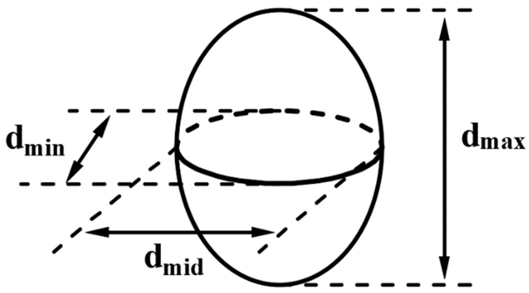
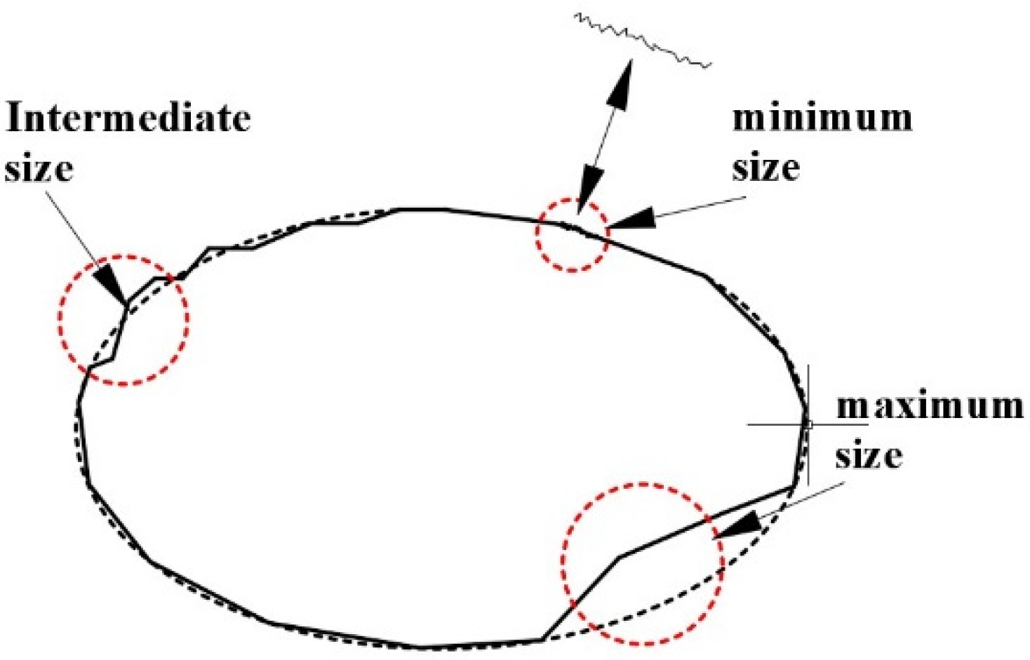
Shapes were defined based on their three-dimensional dimensions (dmax - maximum dimension, dmid - middle dimension, dmin - minimum dimension), where dmax represents the longest dimension of the falling rock, dmin is measured perpendicular to dmax, and dmid is obtained by measuring a plane perpendicular to both dmax and dmin, as illustrated in Figure 4.
For rocks with nearly equal three-dimensional dimensions (dmaxdmiddmin), they were classified as spherical in shape, including spheres and regular polyhedra. For rocks where the maximum dimension was significantly larger than the other two dimensions (dmax > (dmiddmin)), they were classified as cylindrical, including cylinders and prisms. For rocks where the two larger dimensions were approximately equal ((dmaxdmid) > dmin), they were classified as disc-shaped, including discs and hemispheres.
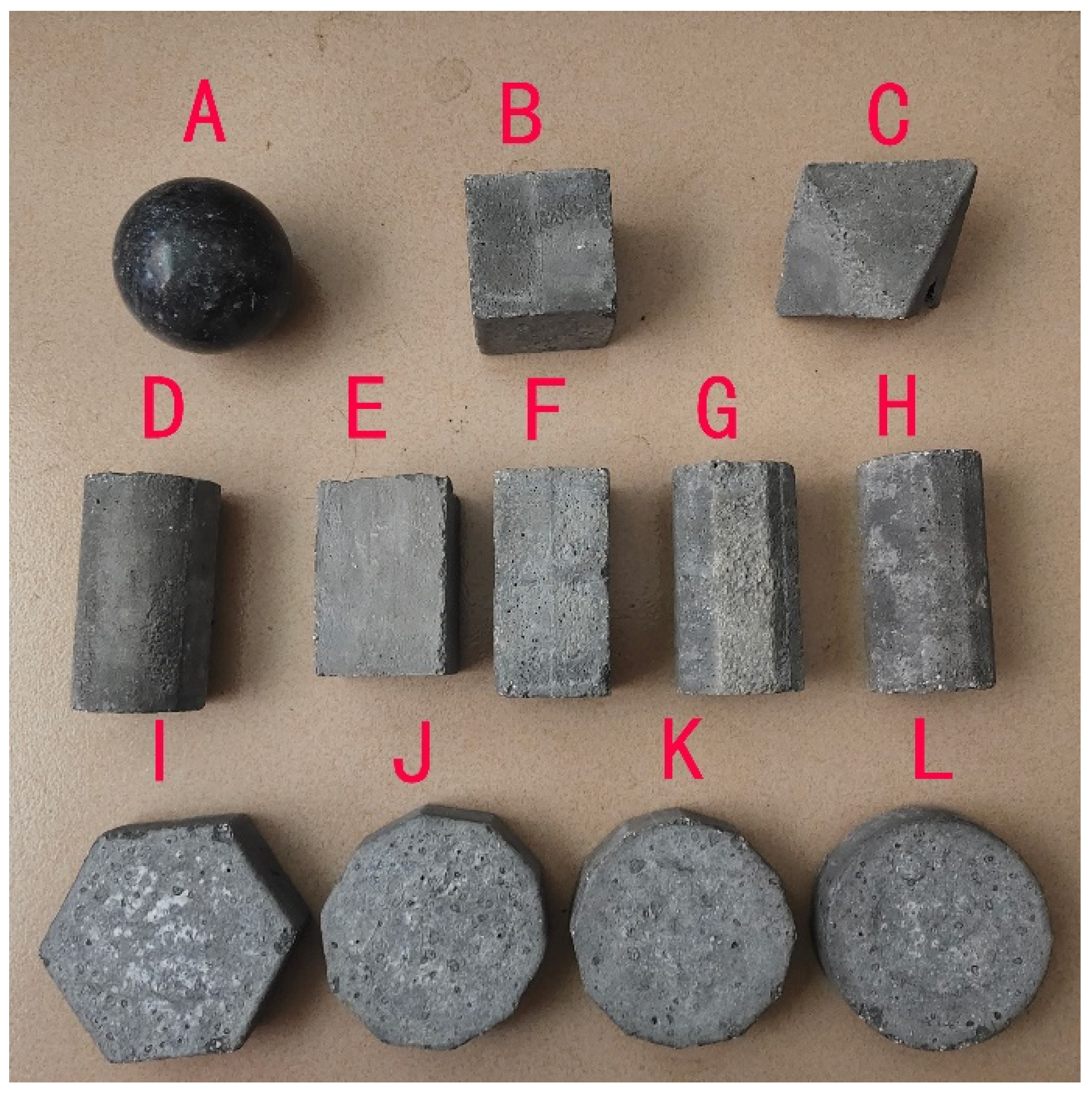
When selecting the test block material, considering the density and hardness of the material may affect its rolling characteristics. In order to avoid the interference of other influencing factors in the model test, C60 concrete were used to made test blocks. The ingredients of C60 concrete are shown in Table 2. The mold can be used to cast any shape test block, and the high hardness can ensure that it does not break during the rolling process. The test block is shown in Figure 5, and the specific shape parameters are shown in Table 3.

2.2.2. Slope Surface Material Parameters

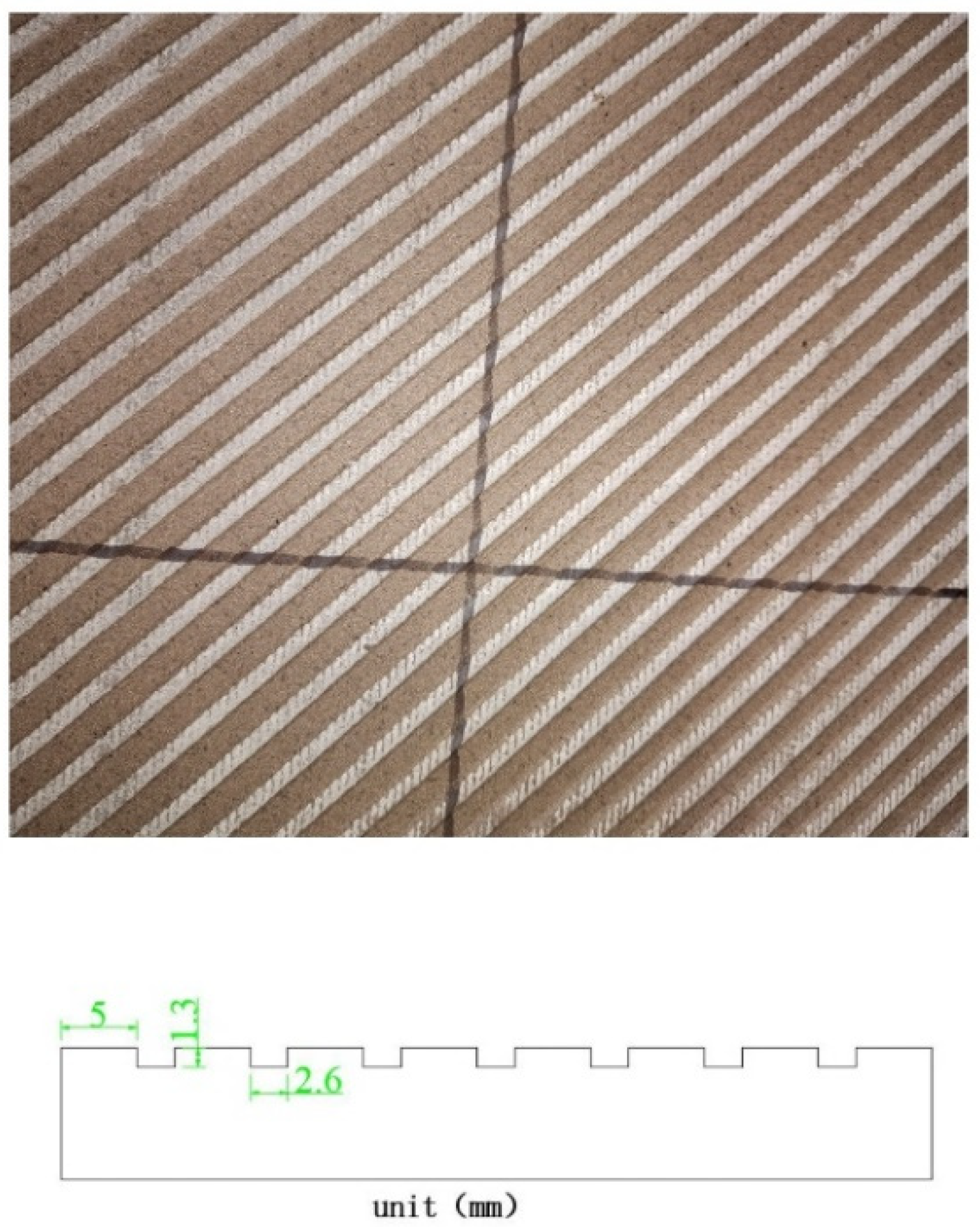
To ensure uniform roughness, the backside of ceramic tiles was selected as the slope surface material for the experiments, as illustrated in Figure 6. Prior to the experiments, the sliding friction coefficient between the test blocks and the ceramic tile surface was determined, following the proposed method for calculating slope surface friction coefficients [37]. The rolling friction coefficient μ on the ceramic tile panel was measured to be 0.09. It was ensured that the sliding friction coefficient of the test blocks exceeded the rolling friction coefficient, guaranteeing that the blocks would only experience rolling after being released from the slope.

2.3. Experimental Procedure

When determining the slope range of the model experiment, Wei [38] analysis results of multiple historical rock collapse disaster event data were referred to, and 30 °, 45 °, and 60 ° were taken as the test slopes. The distance from the test block on the slope to the bottom of the slope is defined as the release height h. Within the range of 0.3m to 0.9m, take one height every 0.15m as the release height for the test.
Initially, the slope was adjusted to the desired angle using support rods to simulate the single-slope rolling of rocks. The slope angle at the time of release should exceed the rolling friction angle to ensure continuous tilting of the test blocks. Secondly, the high-speed camera was set up in advance to fully capture the motion plane of the entire experimental apparatus. Lastly, it was ensured that the test blocks were in a stationary state at the time of release, ensuring that the reason for the blocks tilting and subsequently rolling was that the torque resisting tilting was smaller than the tilting torque.
To ensure that the offset areas on both sides of the test blocks during their rolling on the slope were of the same size, the test blocks were released from the midpoint of the slope during the experiment. The specific position of the release point could be determined by the distance h from the release point to the slope bottom.
The following methods were employed for video processing based on the grid lines drawn on the apparatus:
Determine the corresponding proportionality relationship between actual dimensions and dimensions in the video: Lactual: Limage = k:1, for converting experimental data.
stablish a coordinate system on the rolling surface using grid lines and determine the test block's rolling trajectory based on the coordinates. The initial position coordinates are (x0, y0), and after continuous rolling, the coordinates of the test block are (xn, yn). Calculate the distance between the two points, which, after scaling, represents the actual length, denoted as L [39], i.e.,
L = k ( x n x 0 ) 2 + ( y n y 0 ) 2
v = k ( x n x n 1 ) 2 + ( y n y n 1 ) 2 2 Δ t + k ( x n + 1 x n ) 2 + ( y n + 1 y n ) 2 2 Δ t
Analyze the entire rolling process frame by frame, recording the test block's rolling trajectory from the moment of release until it comes to a stop, thus obtaining the actual rolling distance S on the slope surface.

2.4. Analysis of Experimental Results

2.4.1. Influence of Block Shape on Rolling Speed

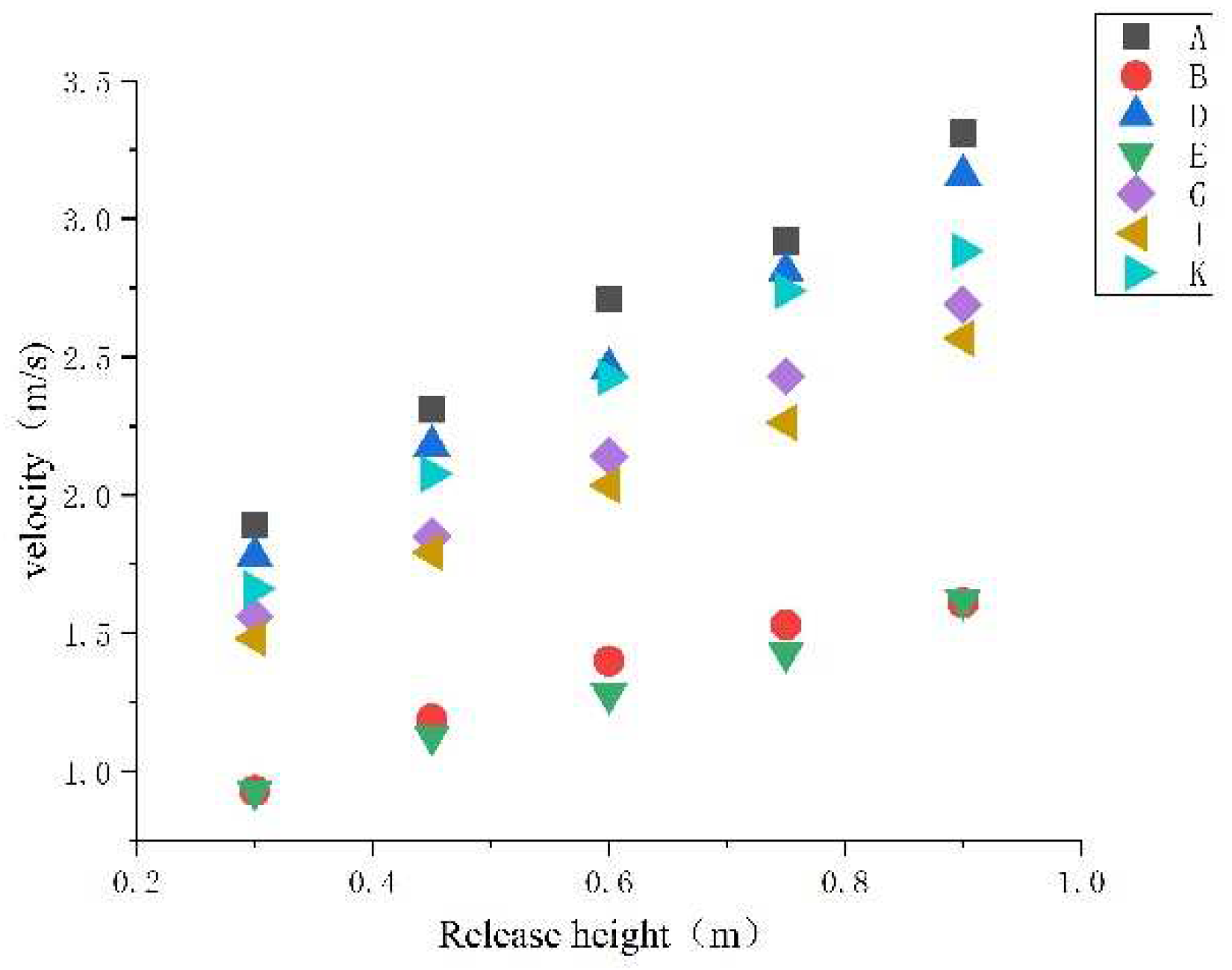
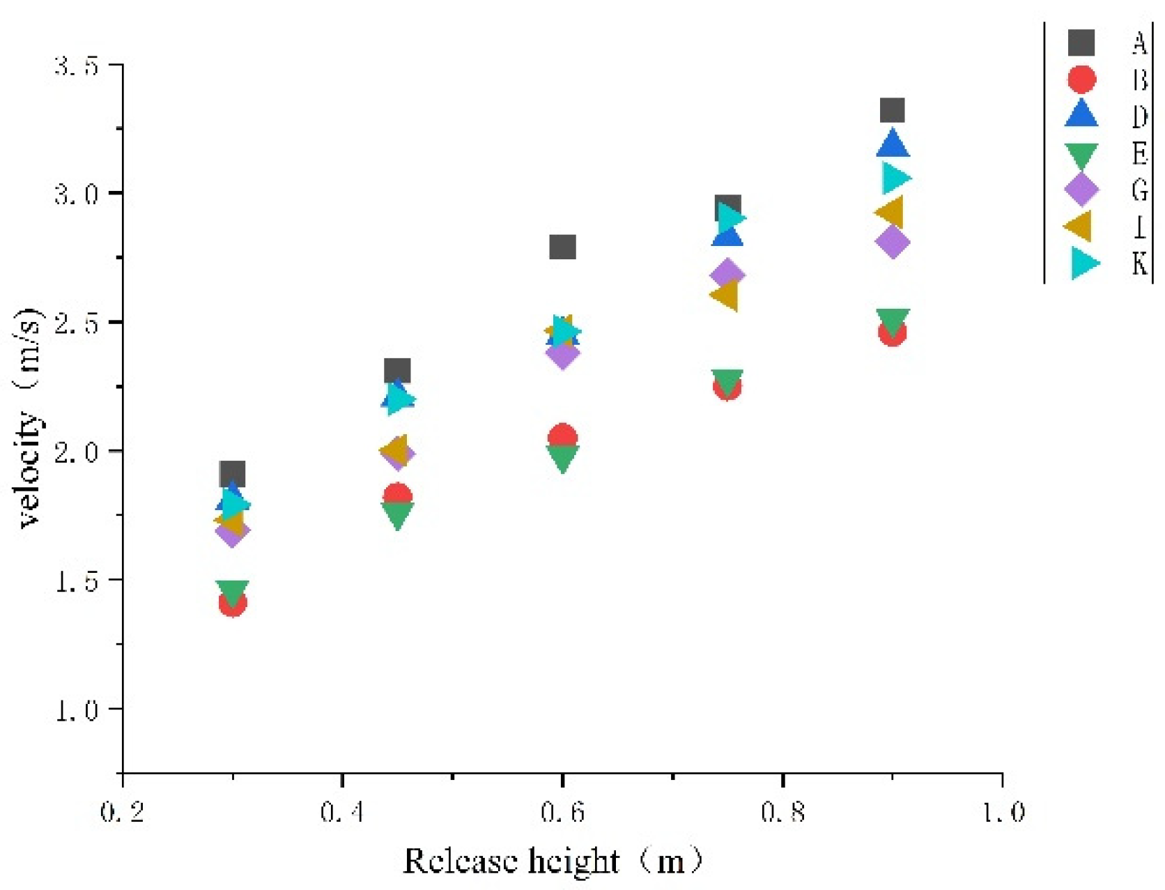
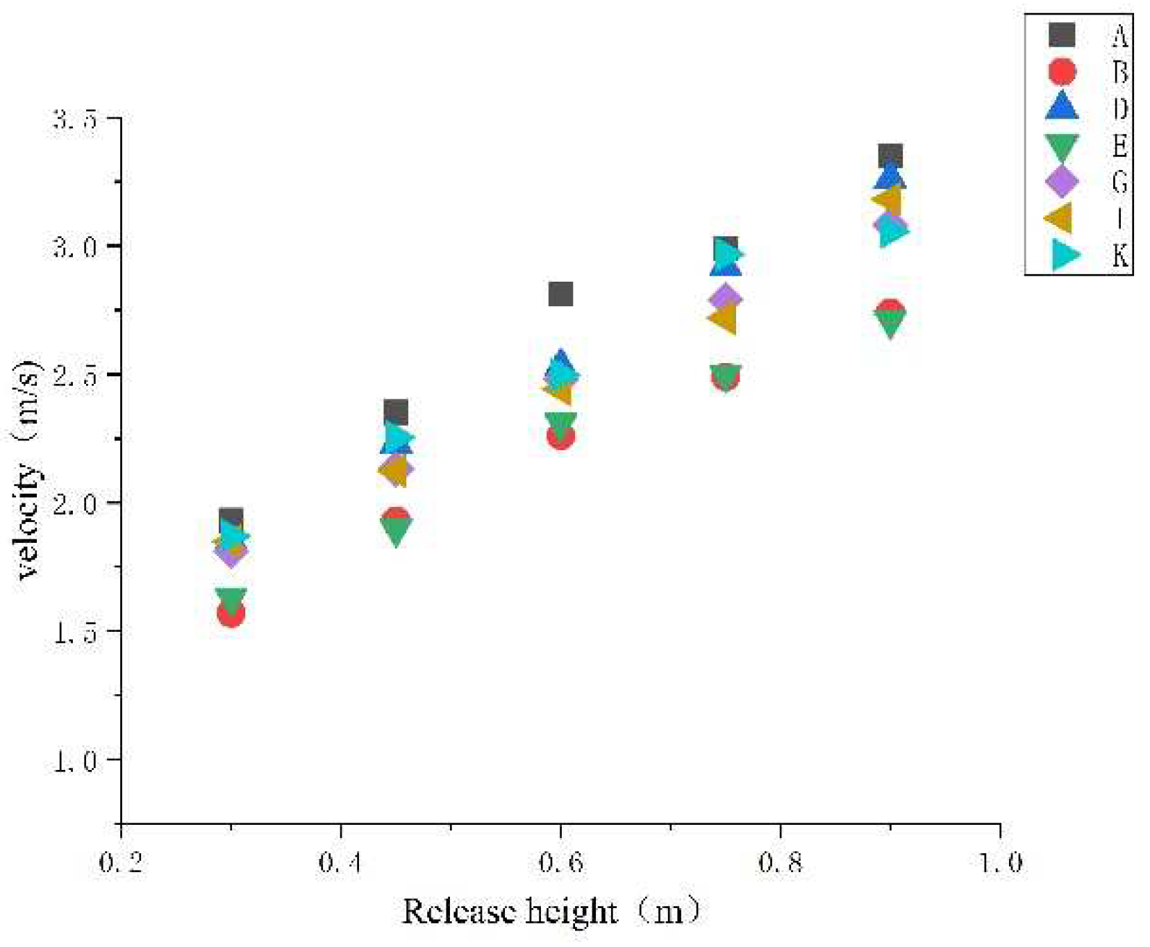
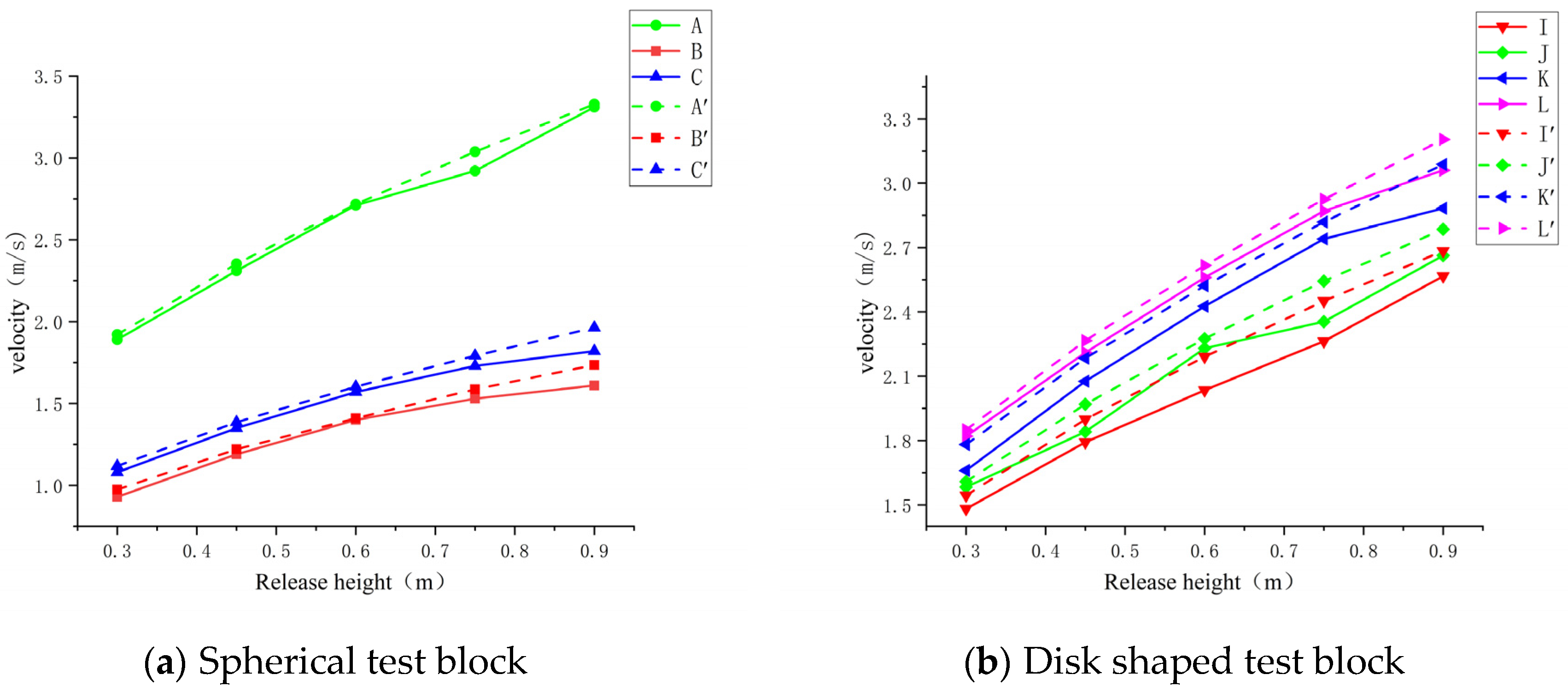
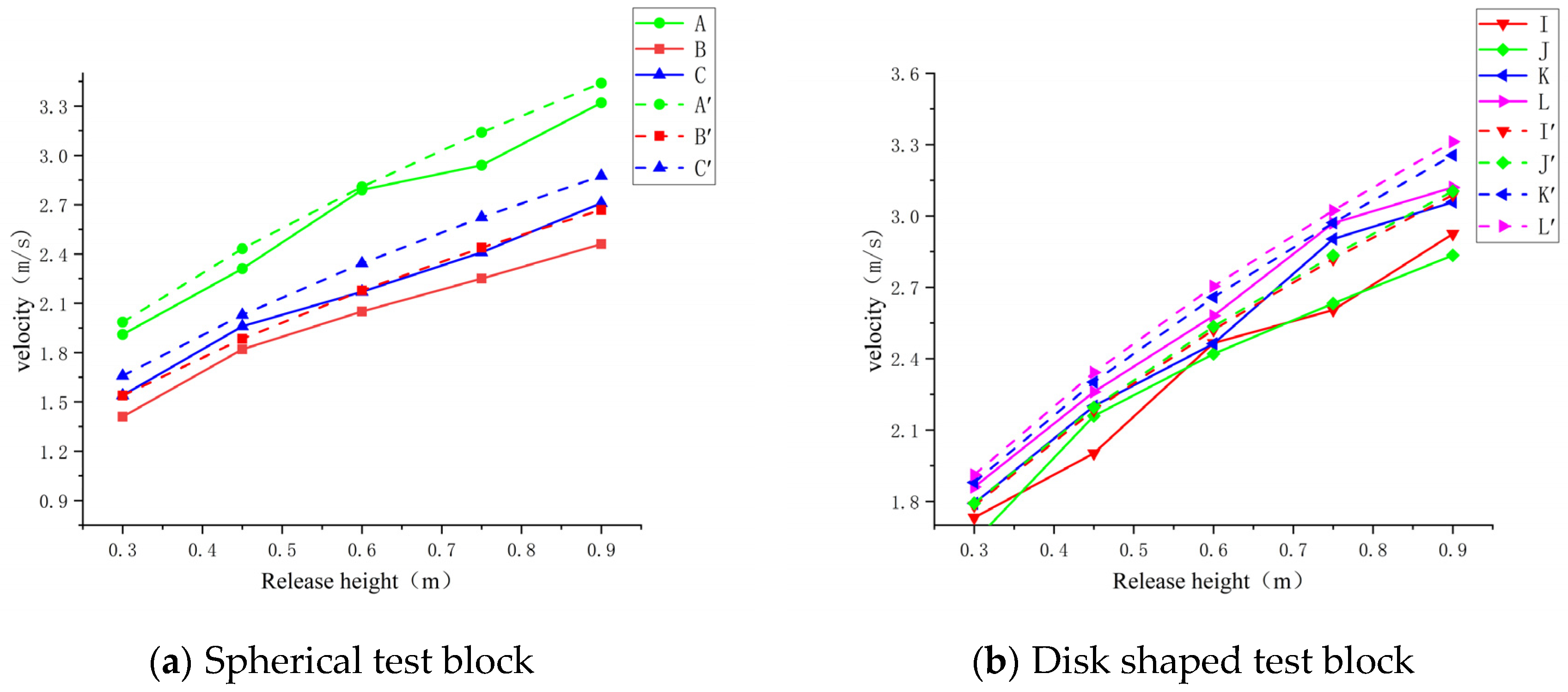
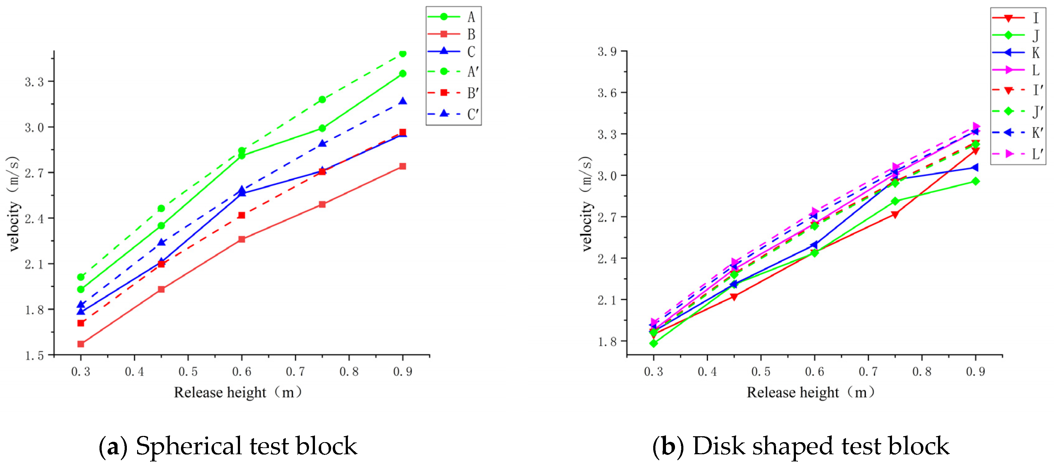
As evident from Figure 7, Figure 8 and Figure 9, under identical conditions, spherical block A exhibits significantly higher rolling speed compared to blocks B and E. Analysis suggests that the rolling resistance experienced by spherical block A during rolling depends on the roughness of the rolling slope. In contrast, blocks B and E primarily experience rolling resistance based on their contact with the rolling surface, specifically the contact area between the block and the surface after each roll. Blocks B and E have much larger contact areas with the slope during rolling compared to block A, substantially increasing the rolling resistance torque they need to overcome. Hence, for blocks rolling on a hard slope surface, their shape is the primary factor leading to energy consumption.
From Figure 9, it can be observed that at a 60-degree slope, for blocks E (roundness of 0.9) and G (roundness of 0.97) with equal mass, released from a height of 90 cm, the actual speeds are 2.71 m/s and 3.08 m/s, respectively. Block E's speed is 13.65% lower than that of block G, and this phenomenon is consistently observed in experiments with blocks of different shapes. This indicates that the rolling speed of the blocks is somewhat related to the two-dimensional cross-sectional roundness of their rolling surface and is positively correlated with the roundness perpendicular to the rolling surface
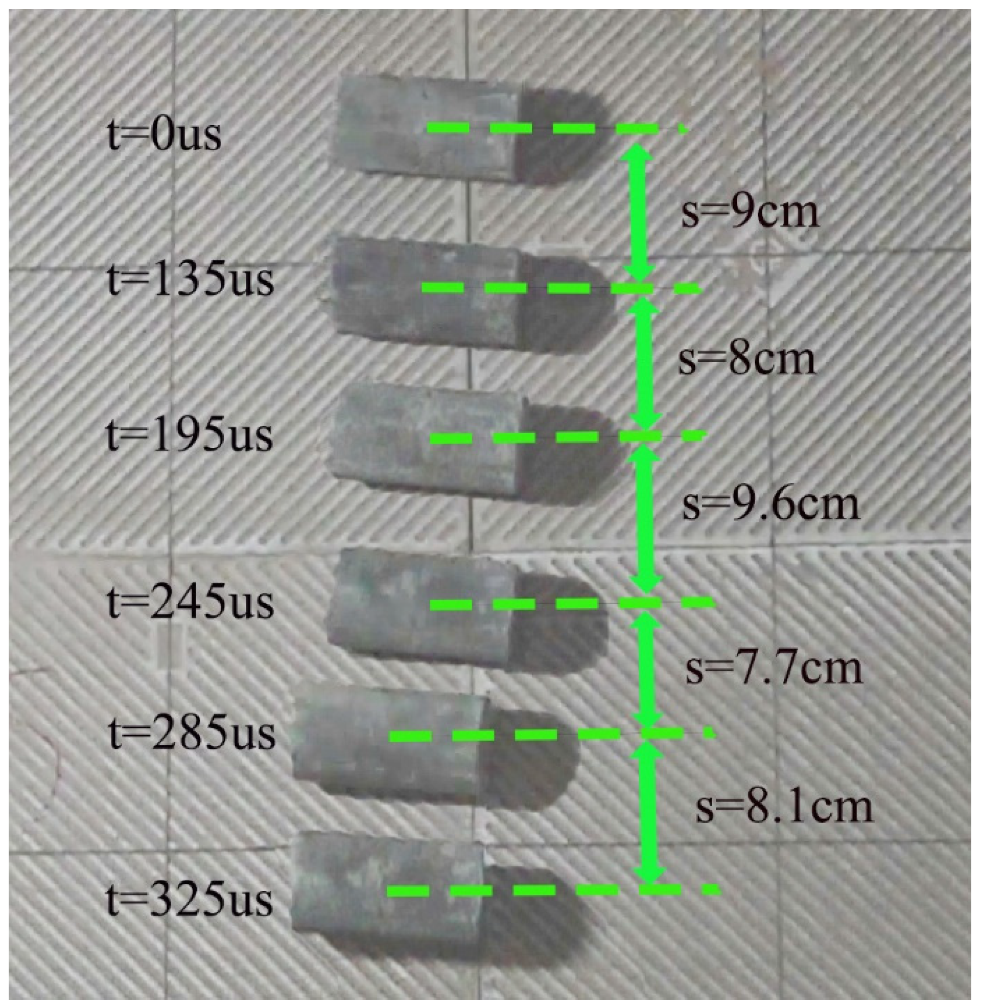
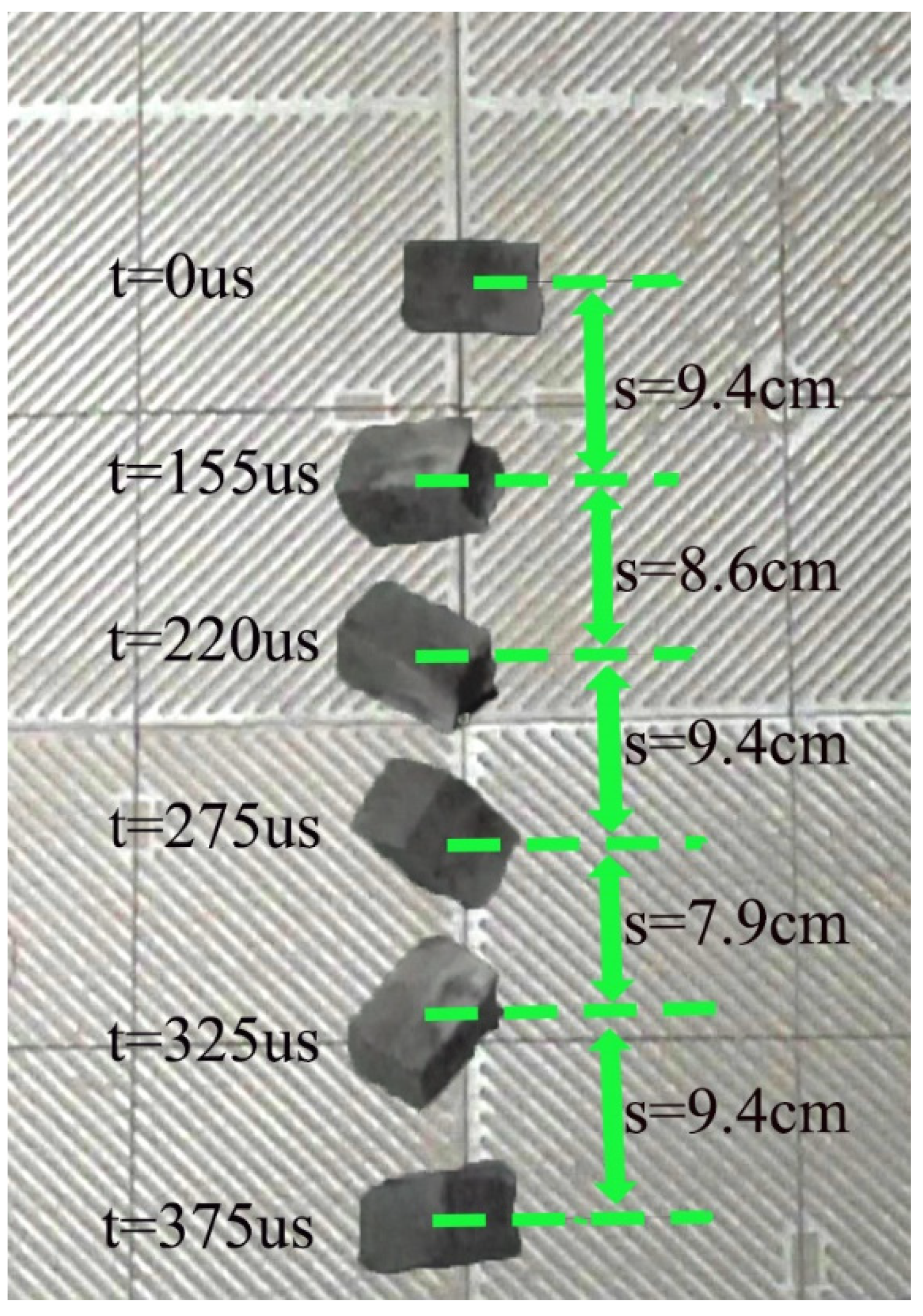
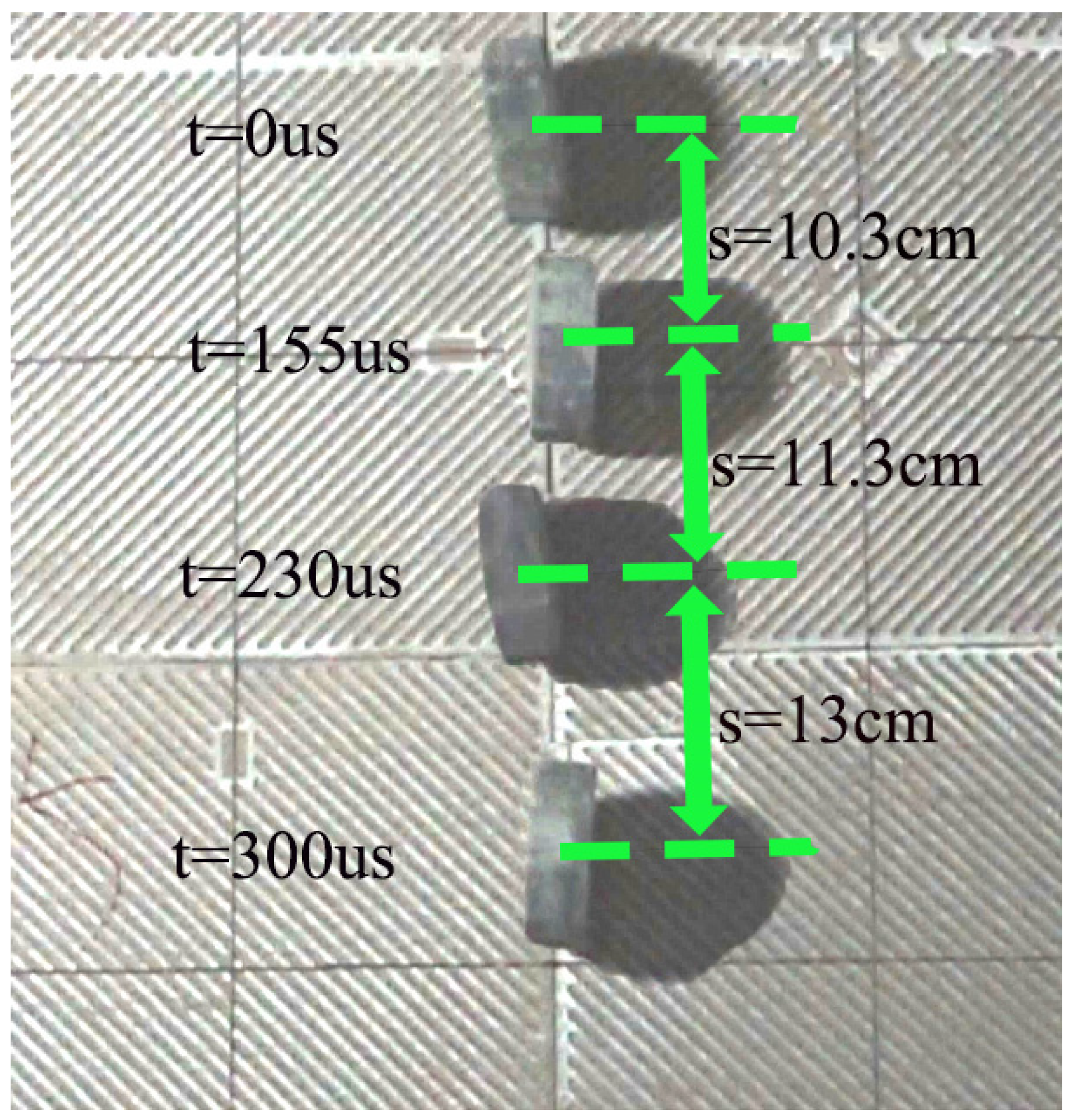
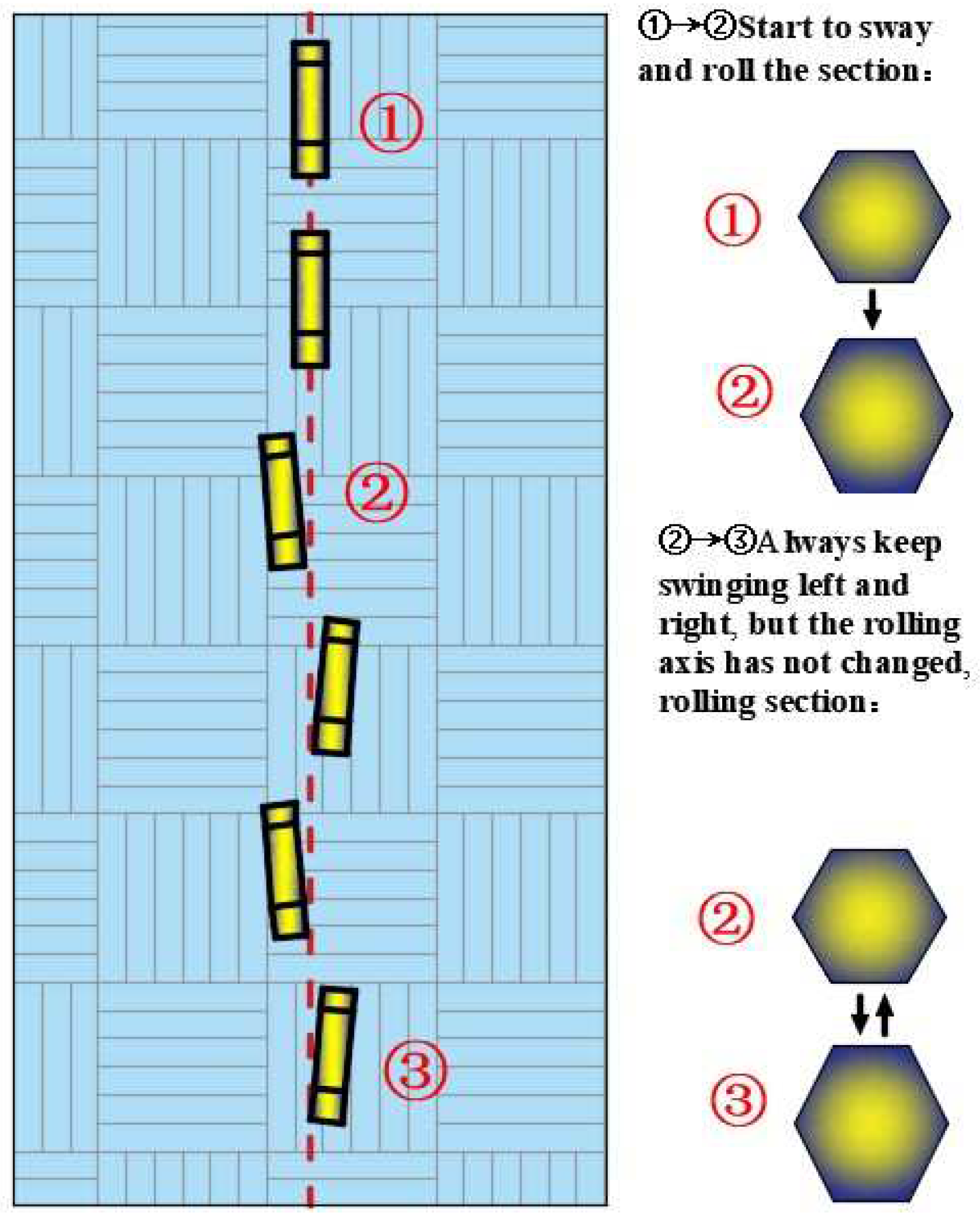
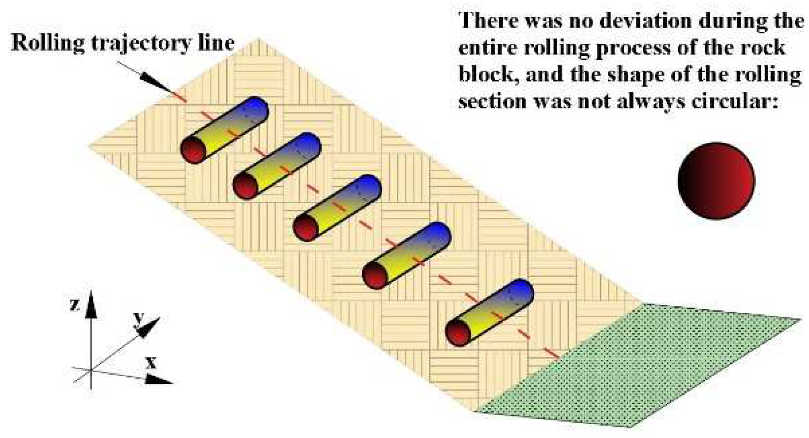
During the test, it was found that when the test block rolled downwards from the slope, it tended to roll around the rolling axis with the least rolling resistance. This aligns with the conclusion drawn by Azzoni [40] through the analysis of field rockfall test data. A parameter called the length-to-width ratio (λ) was defined, where λ = lmin/lmax, with lmax being the maximum length of the block and lmin being the minimum length. Analysis of the experimental data revealed that when λ < 0.33, the blocks typically roll around the axis with the minimum rolling resistance and rarely change their rolling axis, as shown in Figure 10. The lateral offset of the test block in the rolling process is small, which is attributed to the small rolling resistance of the test block itself and the slope surface, so that the test block can maintain the same rolling direction. When 1 > λ>0.33, the test block is usually accompanied by the transformation of the rolling axis in the rolling process, as shown in Figure 11, and the transformation times of the rolling axis positively correlate with the magnitude of λ. For test block E, its rolling resistance is relatively large and the difference in rolling resistance between any two-dimensional sections is not significant. During the rolling process, the rolling axis is easily transformed, and the process of changing the rolling axis will increase energy loss, thereby reducing the rolling speed of the test block. For test block D, its slenderness ratio is also within the range of 1 > λ> 0.33, but due to the small resistance of the initial rolling section when it is released, it does not change the rolling axis and has a small lateral offset, just like the test block G. From this, it can be seen that when rolling on a slope without obstacles, the transformation of the rolling axis of the test block is positively correlated with both the slenderness ratio and the rolling resistance originating from the shape of the test block itself.
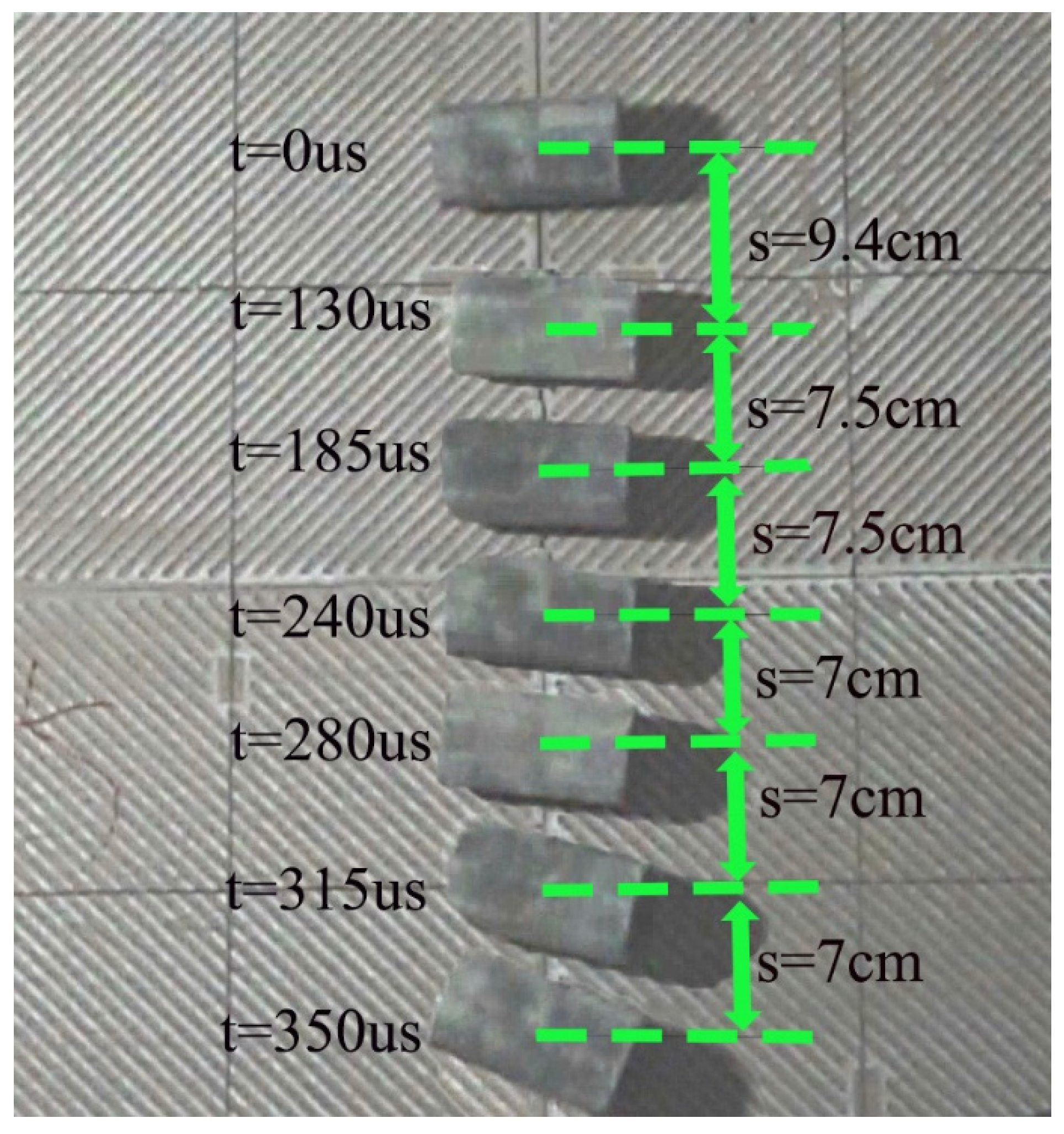
From Figure 9, it is evident that at a release height of 45 cm, despite block D having slightly greater roundness compared to block K, its rolling speed (2.23 m/s) is slightly lower than that of block K (2.26 m/s). The reason for this phenomenon is that during the rolling process, block K's moment of inertia is greater than that of block D, allowing block K to possess more rotational kinetic energy when rolling down the slope, as depicted in Figure 12 and Figure 13. Consequently, block K overcomes some of the rolling resistance caused by its shape, leading to its rolling speed approaching that of block D, and in some cases, even surpassing it. And the contact area between test block K and the rolling surface is smaller than that of test block D, but the center of gravity is higher than that of test block D, resulting in the left and right shaking of test block K during the rolling process. But under the action of rotational inertia, it can still maintain the initial rolling axis rolling. The shaking of test block K during the rolling process consumes some of the rolling kinetic energy, resulting in a decrease in the rolling speed of the test block.

2.4.2. Influence of slope and release height on rolling speed of test blocks with different shapes

For spherical test block A, which can ignore the rolling resistance caused by its own shape, under the premise of the same release height, its rolling distance and offset of the slope will decrease with the increase of the slope, and the rolling resistance required to overcome the slope characteristics will also decrease. From this, it can be seen that for spherical test blocks, under the same conditions as other influencing factors, the rolling speed is positively correlated with the slope angle. In other words, for test blocks with high rolling resistance, a decrease in slope at the same height will increase the rolling distance of the test block on the slope, thereby increasing the energy consumption of the test block. When the slope is gentle and the rolling distance is too long, there may be a situation where the rolling speed of the test block continues to decrease and eventually stops on the slope.
As can be seen from Figure 7 to Figure 9, for the test block released at rest, with the increase of the release height, the test block has greater gravitational potential energy when it is released, and the rolling speed of the test block with all shapes increases with the increase of the release height. However, the increasing amplitude of the rolling speed of different test blocks with the increase of the release height is very different. The most obvious difference is the change of the rolling speed of test block A and test block B with the increase of the height in Figure 7. The rolling speed increase of test block A is much greater than that of test block B. It can be seen that for test block with large rolling resistance, increasing its release height on the slope has no obvious effect on its rolling speed. However, this phenomenon mainly occurs when the slope is small. As shown in Figure 8, when the slope is 45°, the increase of the rolling speed of all test blocks can be obviously observed with the increase of the release height. The reason for this may be that the overturning moment of the test block is smaller when the slope is smaller, the resistance needed to overcome each roll is larger, and the distance required to leave the slope is longer. Therefore, even if the release height increases, for the test block with large rolling resistance, a large part of the increased height potential energy is still consumed during rolling, resulting in an insignificant increase in rolling speed.
To sum up, it can be seen that the rolling resistance in the rolling process of rockfall comes from the roughness of the slope and the shape of the rockfall. The difference in shape makes the rockfall have different roundness, moment of inertia, slenderness ratio and the contact area with the slope during the rolling process, thus affecting its rolling speed. The rolling speed of different shapes of rockfalls on the slope is also affected by the release height and slope, and these factors should be integrated in the calculation formula.

3. Theoretical Analysis

3.1. Model Derivation

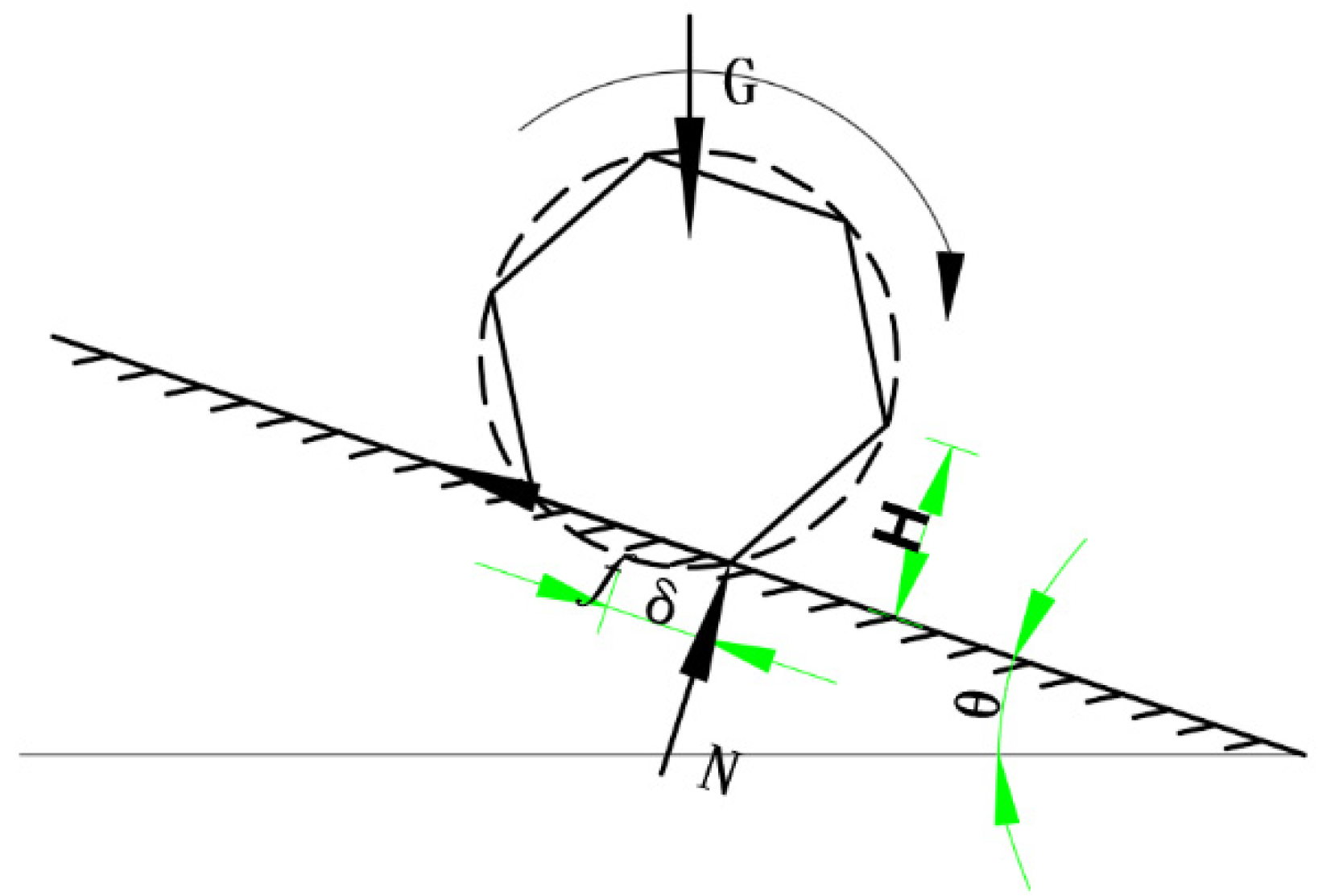
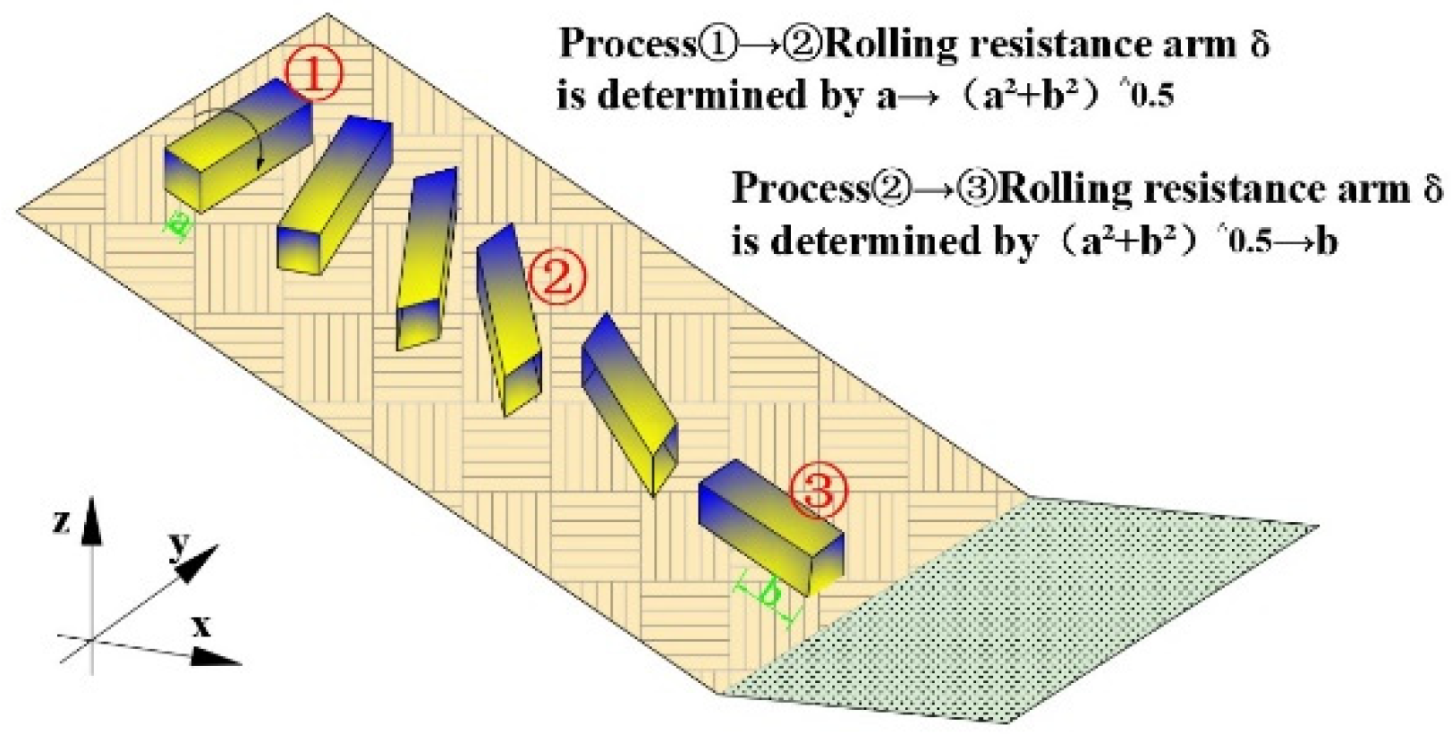
The current research has made it clear that the shape of falling rock will affect its rolling characteristics, and pointed out that falling rock with different shapes will suffer different rolling resistance during rolling, but no clear definition of rolling resistance has been given. In order to accurately describe the influence of rock fall shape on its rolling characteristics, two concepts related to rolling - rolling resistance and rolling resistance distance - need to be established [41]. For the same test block placed stationary on the slope, its rolling resistance arm δ is determined by the size of the contact surface between the test block and the slope, as shown in Figure 14.
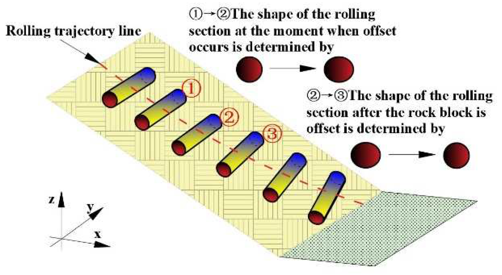
Through the analysis of data obtained from model experiments, the mechanisms by which rock shape influences its rolling speed have been identified. Consequently, this paper defines a shape parameter that reflects the overall shape and local convex-concave characteristics of a rolling stone. This parameter is based on the difference between the two-dimensional cross-sectional area perpendicular to the shortest and longest dimensions of the falling stone and the area of its minimum circumscribed circle, as seen in Figure 15. The rolling resistance coefficient ψ, stemming from the shape of the rolling stone, is defined as follows.
ψ = u 1 u 2 u 1
u1—The area of the smallest circumscribed circle of the 2D cross-section of the rolling stone perpendicular to the slope.
u2—The area of the 2D cross-section of the rolling stone perpendicular to the slope.
Additionally, the rolling resistance of a rock also arises from factors such as slope angle and roughness. Taking into account the rolling friction coefficient related to the roughness of the slope [43], the rolling resistance f for rock rolling is defined as:
f = ( μ + ψ ) N
μ—Rolling friction coefficient related to the roughness of the slope.
The assumptions made during the derivation are as follows:
(1) The rolling stone experiences rolling but not sliding on the slope. The slope angle θ must satisfy the following condition:
a r c tan H δ θ a r c tan μ
Where: δ—Rolling resistance arm of the rolling stone.
H—Distance from the center of gravity of the rolling stone to the slope.
μ—Rolling friction coefficient related to the roughness of the slope.
(2) The rolling stone and the slope do not deform during the rolling process.
(3) The rolling stone remains intact while rolling on the slope.
According to the principle of conservation of energy, the energy calculation formula for the rolling stone on a rigid slope can be derived as:
E = 1 2 m ( v x 2 + v y 2 ) + 1 2 I ω 2 + f S
vx, vy—Velocities of the rolling stone in the x and y directions during rolling (m/s).
I—Moment of inertia (kg/m2).
ω—Angular velocity of the rolling stone (rad/s).
f—Rolling resistance of the rolling stone (N/m).
S—Actual rolling distance (m).
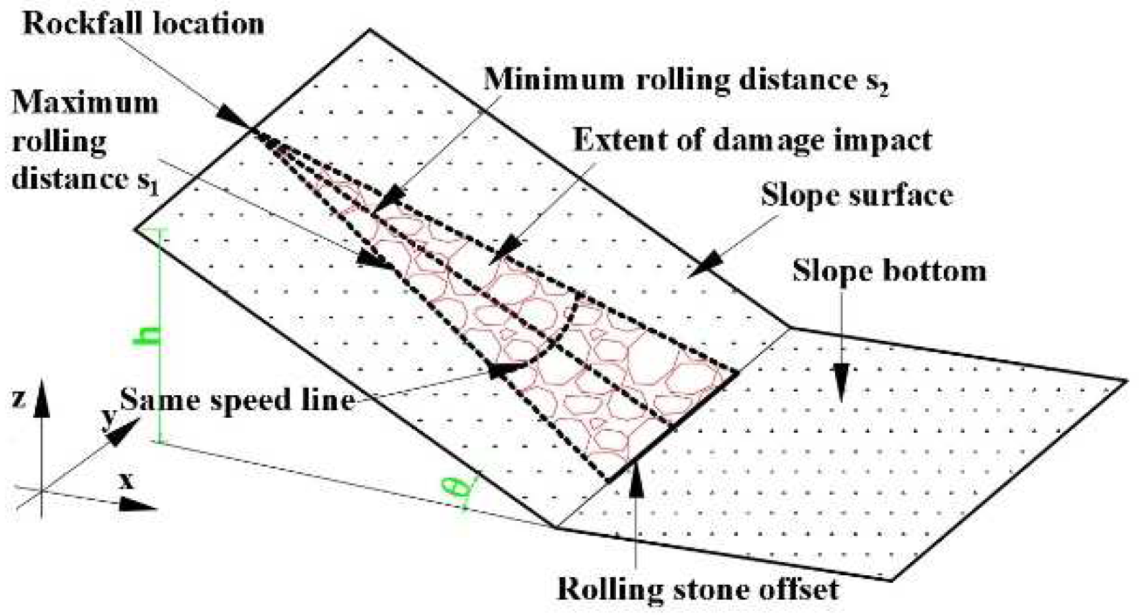
In experiments, the actual rolling distance of the test block can be determined by analyzing the entire process of the block's rolling captured by a high-speed camera during model tests. In practical applications, the shortest and longest rolling distances S1 and S2 of the rolling stone on the slope can be estimated based on the stone's height and the corresponding maximum offset η [44]. The actual rolling distance and the extent of damage can then be estimated based on the specific shape of the falling stone and slope characteristics, as shown in Figure 16
S 1 = h sin θ
S 2 = ( h sin θ ) 2 + ( h sin θ η ) 2
h—Height of the rolling stone's position above the bottom of the slope (m).
In the calculation of the rolling speed of blocks with different length-to-width ratios (λ), it is necessary to consider the situation where the rolling axis changes during the rolling process. For falling stones with 0.33 < λ < 1, it is necessary to calculate the moments of inertia for both the minimum and maximum rolling axes, along with the corresponding rolling friction coefficients and minimum circumscribed circle radii of the two-dimensional cross-sectional shape. These values are used to determine the upper and lower bounds of the rock's rolling speed. For falling stones with λ < 0.33, only the parameters corresponding to the rolling axis with the minimum rolling resistance need to be determined as the theoretical values for calculating the rock's rolling speed.
The formula for calculating the angular velocity of a rolling stone is as follows:
ω = v x 2 + v y 2 R = v R
vx, vy—Velocities of the rolling stone in the x and y directions (m/s).
v—Rolling speed of the rolling stone (m/s).
R´—Minimum circumscribed circle radius of the two-dimensional cross-section perpendicular to the slope (m).
For non-circular cross-sectional shapes of rolling stones, the following modification can be made:
ω = ω d k
dk— Circularity of the cross-section, dk=2πR´/c.
c—Circumference of the minimum circumscribed circle of the cross-section (m).
By combining formulas (4) and (8) to solve formula (6), the range of the rolling speed of the rolling stone (v1 < v < v2) can be obtained, where v1 and v2 represent the upper and lower bounds of the rolling stone's rolling speed, respectively:
v 1 = 2 [ m g H S ( ψ 1 + μ ) N ] m + I 1 ( R 1 d k 1 ) 2
v 2 = 2 [ m g H S ( ψ 2 + μ ) N ] m + I 2 ( R 2 d k 2 ) 2
dk1, dk2—Maximum and minimum circularities of the two-dimensional cross-sectional shape perpendicular to the rolling axis.
ψ1, ψ2—Maximum and minimum rolling friction coefficients corresponding to the shape.
I1, I2—Maximum and minimum moments of inertia corresponding to the shape (kg/m2).
R1´, R2´—Minimum circumscribed circle radii corresponding to the maximum and minimum circularities of the shape (m).
Similarly, the maximum and minimum rolling energies of the rolling stone (E1 and E2) can be obtained:
E 1 = 1 2 m v 1 2 + 1 2 I 1 ( v 1 R 1 d k 1 ) 2
E 2 = 1 2 m v 2 2 + 1 2 I 2 ( v 2 R 2 d k 2 ) 2
Specific calculation parameters for the test blocks are provided in Table 4.

4. Experimental Data Comparative Analysis

4.1. Calculation of Speed v1, v2, and Comparison with Experimental Values
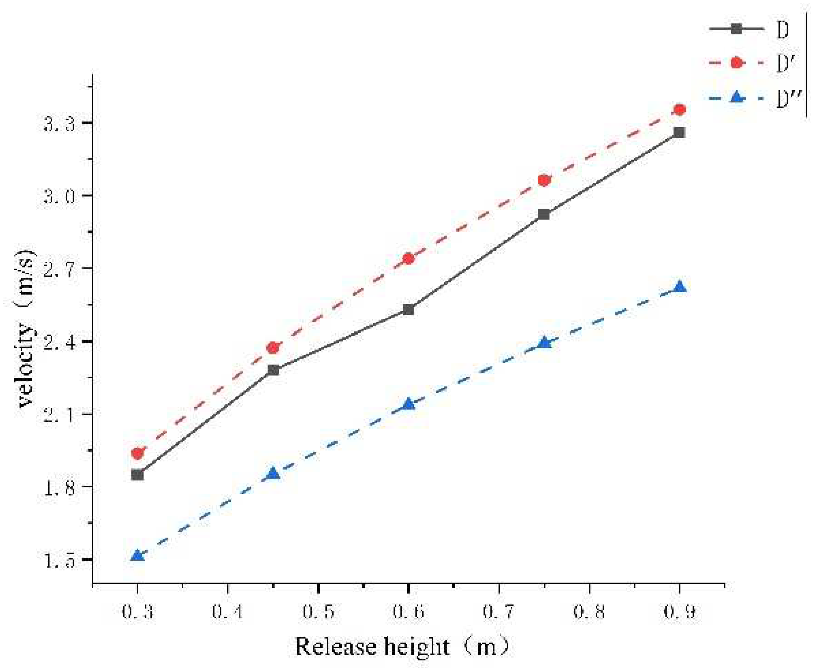
For blocks with λ < 0.33, their rolling speeds can be calculated using Formula (11), and the calculation results are compared with experimental results, denoted as the experimental speed values and theoretical speed values for each block.
In Figure 17 to Figure 19, the maximum error between the theoretical values and experimental values for blocks of different shapes is 10%, with an average error of 5.126%. Through the analysis of experimental data, the reasons for the occurrence of errors are summarized as follows:
(1) In the process of formula derivation, sliding friction losses during the rolling process were not considered. However, it was observed in the experiments that as the slope angle increases, some blocks with relatively high rolling friction coefficients (e.g., blocks B and C) tend to experience a small amount of sliding friction when rolling on the slope. These blocks have higher overturning moments, and when the slope angle approaches the sliding friction angle, the forces acting on the slope surface after rolling can result in a small amount of sliding friction. This phenomenon gradually decreases with increasing rotational kinetic energy.
(2) For some blocks with relatively low rolling friction coefficients, during the process of shifting direction until stabilization, the two-dimensional cross-section used for calculation is not exactly perpendicular to the actual rolling axis, leading to a slightly larger actual rolling resistance than the calculated value. For example, blocks D and L exhibit this behavior, and during the directional shift in the rolling process, the two-dimensional shape that is approximately perpendicular to the rolling axis resembles an ellipse, as shown in Figure 27. However, calculations are still performed assuming a circular shape, resulting in errors. In contrast, for spherical blocks, the roundness of any cross-section is 1, so even if there is a directional shift during rolling, the two-dimensional cross-section perpendicular to the rolling axis remains consistent with the one used for calculation, resulting in smaller errors between the calculated and theoretical values.
(3) For some blocks with small contact areas with the slope surface and a high center of gravity, rocking may occur during the rolling process, consuming some energy. For example, blocks I, J, K, and L exhibit this phenomenon, and it becomes more pronounced as the contact area with the slope surface decreases. The position of the rolling axis oscillates with the change in the center of gravity, causing the entire rolling process to be unstable. However, for blocks rolling on either side, the rotational inertia keeps them in a balanced state, as shown in Figure 20. In contrast, blocks J and K, which have the same circularity and volume as blocks G and H, do not exhibit rocking during rolling because they have larger contact areas with the slope surface and a lower center of gravity. As shown in Figure 21, no energy loss occurs due to rocking during rolling, reducing the error between calculated and experimental values
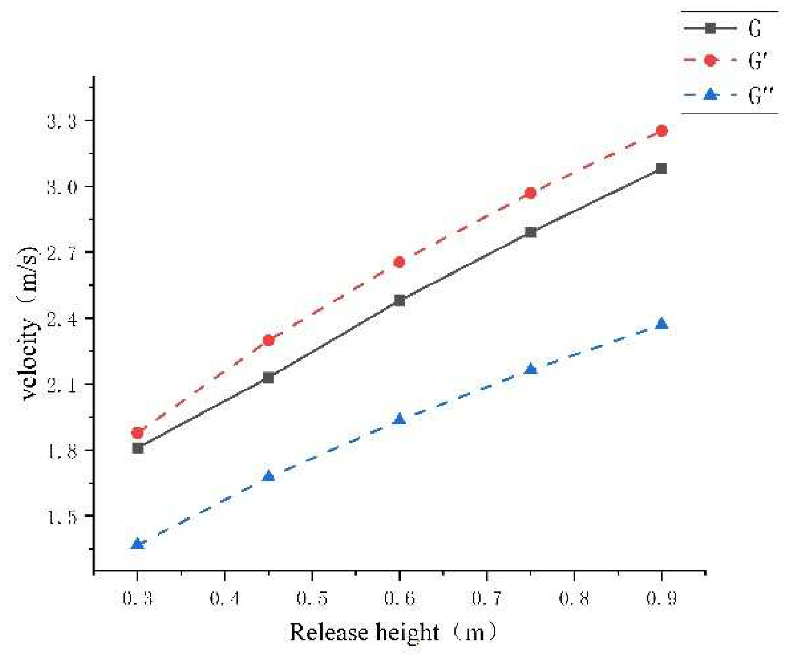
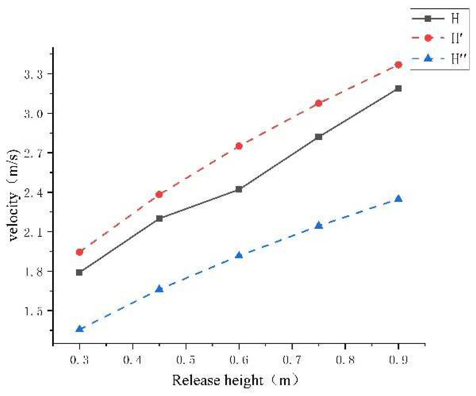
For blocks with 0.33 < λ < 1, it is necessary to consider the situation where the rolling axis changes during the rolling process. Therefore, for such blocks, both the high and low values of the calculated speeds are given using Formulas (11) and (12), denoted as the block with index ´ and the block with index ´´, as shown in the figures below.
Figure 22. Comparison of Rolling Speeds for Block D on a 60° Slope.
Preprints 94395 g022
Figure 23. Comparison of Rolling Speeds for Block E on a 60° Slope.
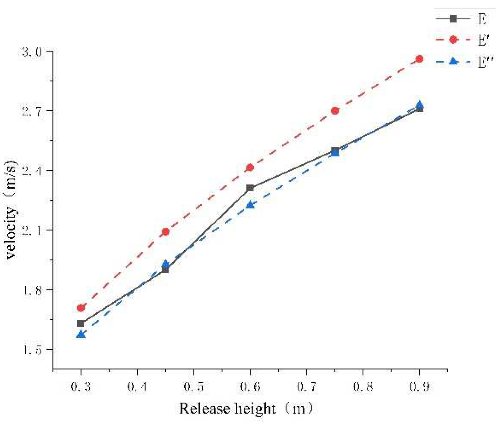
Preprints 94395 g023
Figure 24. Comparison of Rolling Speeds for Block F on a 60° Slope.
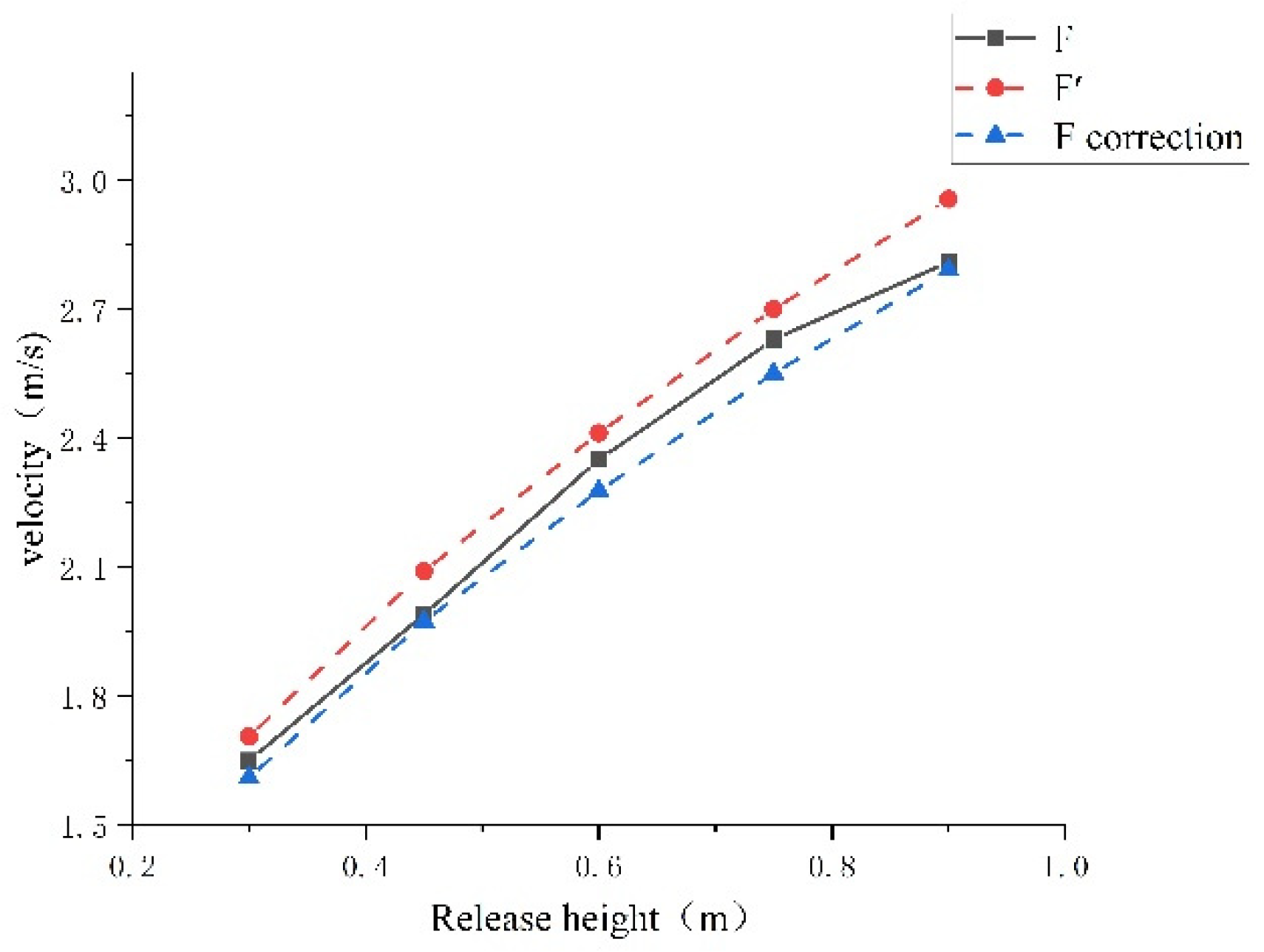
Preprints 94395 g024
Figure 25. Comparison of Rolling Speeds for Block G on a 60° Slope.
Preprints 94395 g025
Figure 26. Comparison of Rolling Speeds for Block H on a 60° Slope.
Preprints 94395 g026
In Figure 22, the experimental speed of Block D closely matches the theoretical high-speed value. This is because Block D has significantly different rolling resistance arm, moment of inertia, and minimum circumscribed circle radius for its two rolling cross-sections. When such-shaped blocks roll on a flat slope, a longer rolling distance is required to change the rolling axis, so the entire process mainly involves rolling around the axis with lower rolling resistance. The actual speed from a 0.6m height release is situated between the high and low theoretical values. During the actual rolling process of the model experiment, there was a slight deviation in the rolling axis, as shown in Figure 27, but the deviation was small, and the block did not complete the change of the rolling axis after rolling off the slope. However, the process of changing the rolling axis involves an increase in the rolling resistance arm, which increases energy consumption during rolling, leading to the rolling speed leaning towards the lower calculated value.
Figure 27. Deviation of the Rolling Axis During Block Rolling.
Preprints 94395 g027
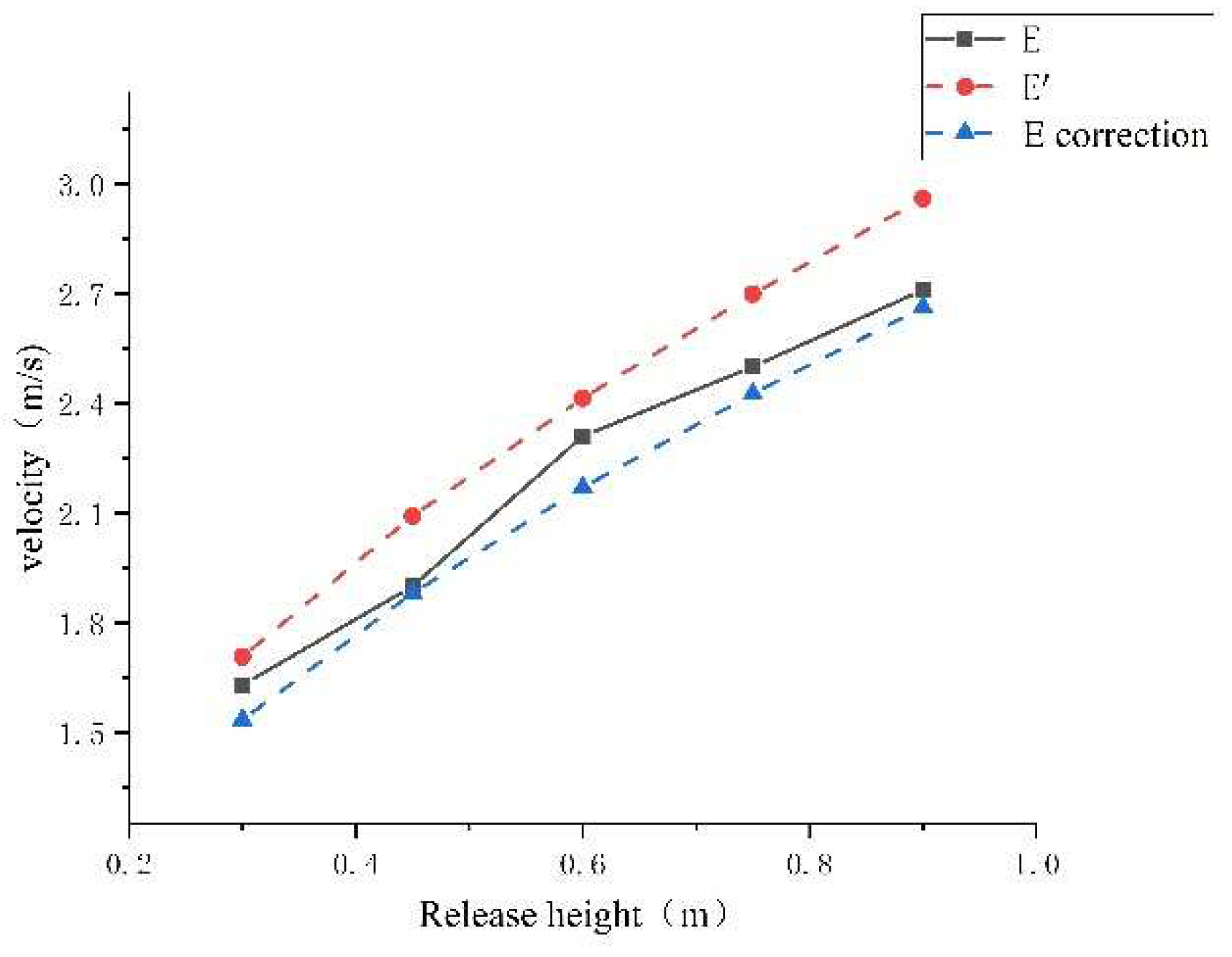
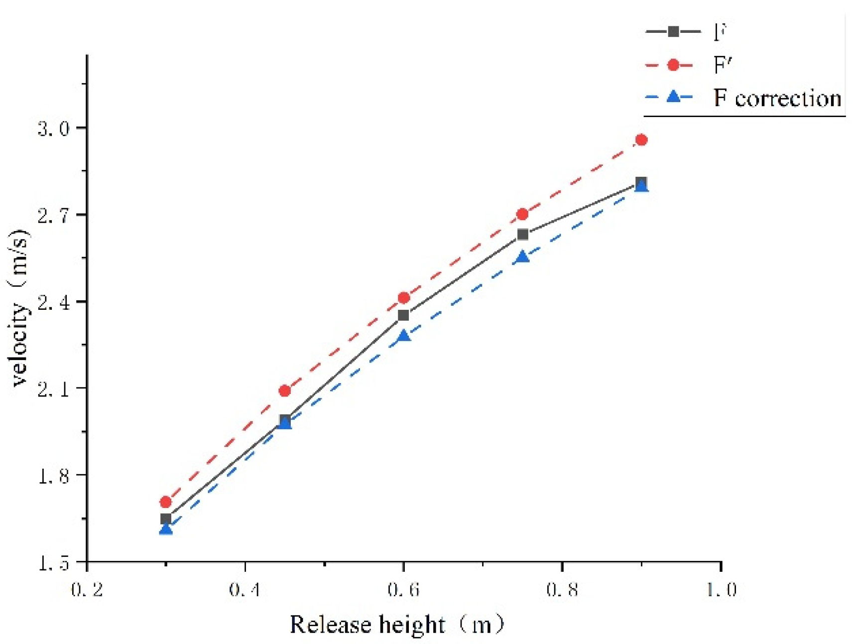
For the cases where the experimental speed is less than the minimum theoretical speed in Figure 23 and Figure 24, the reason is the energy loss caused by slight jumping and rocking of Blocks E and F during rolling. This characteristic is similar to that of disc-shaped blocks. However, due to the similar moment of inertia and rolling resistance arm for rolling around different axes, the rotational inertia required for rolling around the initial rolling axis cannot be maintained. During the rolling process, these blocks go through several consecutive bounces and swings, completing the axis change process at a position before reaching the slope bottom, as shown in Figure 28. With the change in the rolling axis and the axis itself, the rolling resistance arm, deviation, and rolling speed of the block vary to different extents. In addition, comparing the errors between the theoretical and experimental values for Block B and Blocks E and F under the same conditions, it is observed that as the block's aspect ratio increases, the number of axis changes during the rolling process also increases, showing a positive correlation. Therefore, for such-shaped blocks, it is possible for the actual rolling speed to lean towards the lower calculated value or even slightly below it.
For these types of blocks, it is possible to determine the two-dimensional cross-sectional shape perpendicular to the slope surface during the process of changing the rolling axis and calculate the corresponding rolling friction coefficient. This coefficient can then be substituted into the calculation formula to obtain the corresponding rolling speed. The calculation results are shown in Figure 29 and Figure 30, where the experimental values for Blocks E and F fall within the range of the theoretical high and low values.
Based on the above analysis, for blocks with 0.33 < λ < 1, the experimental speeds obtained from the model tests are close to the high and low theoretical speeds calculated by the formulas. The issues identified have also been addressed, further improving the accuracy of the calculation formulas.

5. Discuss

5.1. Countermeasures when there is randomness in the calculation parameters

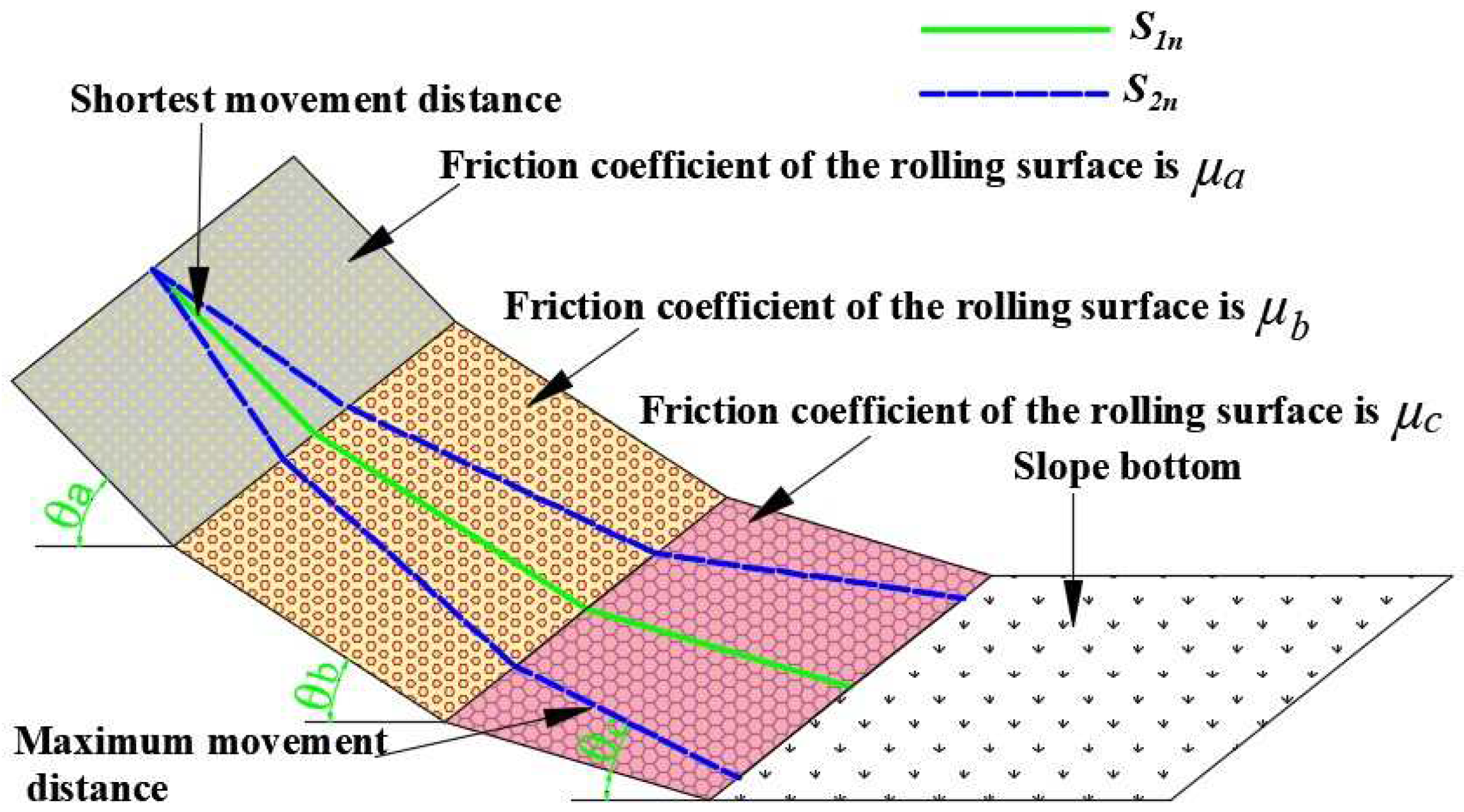
When encountering discontinuity in slope roughness and slope in practical applications, the rolling situation of the test block on the slope can be segmented according to the changes in roughness and slope (n), where n is taken based on the changes in roughness and slope. As shown in Figure 31, formulas (7) and (8) are used to calculate the shortest and longest rolling distances S1n and S2n of fallen rocks on different rolling slopes, and the rolling distances and corresponding slope θn and roughness μn are substituted into formulas (11) and (12), and can be obtained:
v 1 = 2 [ m g h S 1 a ( ψ 1 + μ a ) m g cos θ a S 1 b ( ψ 1 + μ b ) m g cos θ b ... S 1 n ( ψ 1 + μ n ) m g cos θ n ] m + I 1 ( R 1 d k 1 ) 2

5.2. Countermeasures when there is randomness in the calculation parameters

The calculation formula can be used to calculate the speed and energy of rockfalls in the continuous rolling stage, but is not applicable to the stages of continuous sliding, jumping, and free falling, as well as the situation where rockfalls break during the rolling process. For potential threats of rockfall on unobstructed and potholed flat sloping surfaces, after mastering the location, three-dimensional size, density, slope roughness, and other information of the rockfall, the formula can calculate the speed and impact energy range of the rockfall as it rolls off the slope. At the same time, combined with the maximum offset of the rockfall, the rolling range of the rockfall and the rolling speed of the falling stone at any position within this range can be predicted.

6. Theoretical Analysis

6.1. Conclusions

(1) Through model experiments, the influence of the shape and size of rockfalls on rolling speed was analyzed, and it was found that the shape of rockfalls is the main factor affecting their rolling speed. Under the same conditions, the rolling speed of rockfalls is positively correlated with the roundness of their two-dimensional rolling cross-section shape. For circular rockfall, the initial rolling state can be maintained during the rolling process under the action of rotational inertia, indicating that the rotational inertia of the rockfall also affects its rolling characteristics.
(2) The influence degree of slope and release height on different shapes of rockfalls is different. When the slope is small, for the rockfall with large rolling resistance, the increase of the release height has little effect on its rolling speed, while the rockfall with small rolling resistance has no such situation. After the increase of slope, the growth rate of rockfall rolling speed has increased significantly.
(3) The relationship between rockfall shape and rolling resistance is analyzed. It is concluded that the magnitude of the rolling resistance depends on the rolling resistance moment in contact with the rolling surface during rolling, and the rolling resistance arm δ is determined by the size of the contact surface between the rockfall and the slope. On this basis, the shape parameter ψ, which quantifies the rolling resistance of rockfall, is proposed by combining the overall shape and local convex and concave characteristics of rockfall.
(4) By introducing the shape parameter ψ into the kinematic equation, the formulas for calculating the rolling velocity and kinetic energy of falling rocks with different shapes and sizes on different roughness slopes are derived. The variable axis phenomenon in the rolling process is taken into account in the formula, and the theoretical range of rolling speed and kinetic energy can be obtained when the rockfall rolls around different rolling axes. When the formula is used in practice, it can be combined with the maximum offset η of different shapes of fallen rocks to estimate the rolling speed and kinetic energy of the rolling region on the slope and any position in the region.
(5) Experimental data were compared with the results from the theoretical formulas, revealing a maximum error of 10% and an average error of 5.126%. Discrepancies between experimental and theoretical values were analyzed, and corrections were made to address these errors. The experimental results fell within the theoretical formula range, confirming the validity of the theoretical calculation formulas for describing block motion characteristics.

6.2. Prospects

In the derivation of the formulas, it was assumed that rigid blocks undergo pure rolling on a flat slope, without considering the possibility of collisions, jumps, breakage caused by different rockfall materials, or the presence of large irregularities and obstacles on the slope. The applicability of the formulas is thus limited. In future research, we aim to investigate the impact mechanisms of collisions, jumps, and other motion characteristics on blocks of various shapes. We will develop formulas to quantify the relationship between block shape and these motion characteristics.

Author Contributions

Conceptualization, F.L.; methodology, G.S.; software, N.H.; validation, N.H.; formal analysis, B.Y.; investigation, G.S.; resources, G.S.; data curation, F.L.; writing—original draft preparation, N.H.; writing—review and editing, H.L.; visualization, Y.Y.; supervision, B.Y.; project administration, G.S.; funding acquisition, G.S. All authors have read and agreed to the published version of the manuscript.

Funding

The work was supported by the Natural Science Foundation of Guangxi, China (No. 2020GXNSFAA297078) and Guilin University of Technology Research Initiation Fund (GUTQDJJ2003031).

Data Availability Statement

The data used to support the findings of this study are available from the corresponding author upon request.

Conflicts of Interest

The authors declare that they have no known competing financial interests or personal relationships that could have appeared to influence the work reported in this paper.

References

  1. Hu, J.; Zhang, S. Research on Trajectory of Rockfall Based on Dynamic Finite Element Method. Journal of Yangtze River Scientific Research Institute. 2021, 38, 73-79+93. [Google Scholar]
  2. Ye, S.; Chen, H.; Tang, H. Rockfall Mitigation Techniques and Its Characteristics. Highway, 2010, 7, 80–85. [Google Scholar]
  3. Lu, G.; Ringenbach, A.; Caviezel, A.; Sanchez, M.; Christen, M.; Bartelt, P. Mitigation effects of trees on rockfall hazards: does rock shape matter? Landslides 2021, 18, 59–77. [Google Scholar] [CrossRef]
  4. Zhang, S.; Yang, X.; Zhou, J. A theoretical model for the estimation of maximum impact force from a rockfall based on contact theory. Journal of Mountain Science, 2018, 15, 430–443. [Google Scholar] [CrossRef]
  5. Asteriou, P.; Tsiambaos, G. Empirical model for predicting rockfall trajectory direction. Rock Mechanics and Rock Engineering, 2016; 49, 927–941. [Google Scholar] [CrossRef]
  6. Gratchev, I.; Saeidi, S. The effect of surface irregularities on a falling rock motion. Geomechanics and Geoengineering. 2019, 14, 52–58. [Google Scholar] [CrossRef]
  7. Hu, J.; Li, S.; Shi, S.; Li, L.; Zhang, Q.; Liu, H.; He, P. Experimental study on parameters affecting the runout range of rockfall. Advances in Civil Engineering 2018. [Google Scholar] [CrossRef]
  8. Pei, X.; Luo, J.; Huang, R. Failure mechanisms of wind-induced post-seismic rockfall hazard. Bulletin of Engineering Geology and the Environment. 2019, 78, 5707–5725. [Google Scholar] [CrossRef]
  9. Sari, M. Evaluating rockfalls at a historical settlement in the Ihlara Valley (Cappadocia, Turkey) using kinematic, numerical, 2D trajectory, and risk rating methods. Journal of Mountain Science. 2022, 19, 3346–3369. [Google Scholar] [CrossRef]
  10. Valagussa, A.; Frattini, P.; Crosta, G. B. Earthquake-induced rockfall hazard zoning. Engineering Geology, 2014, 182, 213–225. [Google Scholar] [CrossRef]
  11. Huang, S.; Lyu, Y.; Peng, Y.; Huang, M. Analysis of factors influencing rockfall runout distance and prediction model based on an improved KNN algorithm. IEEE access, 2019; 7, 66739–66752. [Google Scholar] [CrossRef]
  12. Umili, G.; Taboni, B.; Ferrero, A. M. Influence of uncertainties: A focus on block volume and shape assessment for rockfall analysis. Journal of Rock Mechanics and Geotechnical Engineering, 2023. [Google Scholar]
  13. Farvacque, M.; Corona, C.; Lopez-Saez, J.; Mainieri, R.; Stoffel, M.; Bourrier, F.; Toe, D. Estimating rockfall release frequency from blocks deposited in protection barriers, growth disturbances in trees, and trajectory simulations. Landslides, 2021; 1–12. [Google Scholar] [CrossRef]
  14. Wegner, K.; Haas, F.; Heckmann, T.; Mangeney, A.; Durand, V.; Villeneuve, N.; Becht, M. Assessing the effect of lithological setting, block characteristics and slope topography on the runout length of rockfalls in the Alps and on the island of La Réunion. Natural Hazards and Earth System Sciences, 2021, 21, 1159–1177. [Google Scholar] [CrossRef]
  15. Shirzadi, A.; Saro, L.; Hyun Joo, O.; Chapi, K. A GIS-based logistic regression model in rock-fall susceptibility mapping along a mountainous road: Salavat Abad case study, Kurdistan, Iran. Natural hazards, 2012, 64, 1639–1656. [Google Scholar] [CrossRef]
  16. Zhou, Y. T.; Shi, S. W.; Zhang, Y.; Cai, Q.; Tang, H. M.; Chen, H. K. Calculation method of angular velocity for rockfall motion. Journal of Hunan University (Natural Sciences), 2018; 45(S1), 116–122. [Google Scholar]
  17. Cui, Z.; Shi, Y. F.; Meng, J. Q. Free-fly rolling model of stone on rock slope and control techniques. Journal of Chang'an University (Natural Science Edition), 2018, 38, 25–31. [Google Scholar]
  18. Yang, H. Q.; Zhou, X. P. A new approach to calculate trajectory of rockfall. Rock and Soil Mechanics, 2019, 30, 3411–3416. [Google Scholar]
  19. Oda, M.; Iwashita, K. Study on couple stress and shear band development in granular media based on numerical simulation analyses. International journal of engineering science, 2000; 38, 1713–1740. [Google Scholar] [CrossRef]
  20. Ai, J.; Chen, J. F.; Rotter, J. M.; Ooi, J. Y. Assessment of rolling resistance models in discrete element simulations. Powder Technology, 2011, 206, 269–282. [Google Scholar] [CrossRef]
  21. Gao, G.; Meguid, M. A. On the role of sphericity of falling rock clusters—insights from experimental and numerical investigations. Landslides, 2018, 15, 219–232. [Google Scholar] [CrossRef]
  22. Giani, G. P.; Giacomini, A.; Migliazza, M.; Segalini, A. Experimental and theoretical studies to improve rock fall analysis and protection work design. Rock Mechanics and Rock Engineering, 2004, 37, 369–389. [Google Scholar] [CrossRef]
  23. Ushiro, T.; Kusumoto, M.; Shinohara, S.; Kinoshita, K. An experimental study related to rock fall movement mechanism. Journal of Japanese Society of Civil Engineers, 2006, 62, 377–386. [Google Scholar]
  24. Cui, S. H.; Pei, X. J.; Huang, R. Q. Rolling motion behavior of rockfall on gentle slope: an experimental approach. Journal of Mountain Science, 2017, 14, 1550–1562. [Google Scholar] [CrossRef]
  25. Lü, Q.; Zhou, C. F.; Yu, Y. Experimental study on fragmentation effects of rockfall impact upon slope. Chinese Journal of Rock Mechanics and Engineering 2017, 36(S1), 3359–3366. [Google Scholar]
  26. Zeng, Z.; Zhao, Y.; Lu, H.; Wei, C. Experimental performance study of ground-coupled heat pump system for cooling and heating provision in karst region. Energy and Buildings, 2018, 158, 971–986. [Google Scholar] [CrossRef]
  27. Zeng, Z.; Zhang, X.; Zhao, Y.; Lu, H. Performance of a ground-source heat pump system and the heat-moisture migration of surrounding soils in karst areas. Journal of Performance of Constructed Facilities, 2017, 31, 04017050. [Google Scholar] [CrossRef]
  28. Leine, R. I.; Schweizer, A.; Christen, M.; Glover, J.; Bartelt, P.; Gerber, W. Simulation of rockfall trajectories with consideration of rock shape. Multibody System Dynamics, 2014, 32, 241–271. [Google Scholar] [CrossRef]
  29. Yan, P.; Zhang, J.; Kong, X.; Fang, Q. Numerical simulation of rockfall trajectory with consideration of arbitrary shapes of falling rocks and terrain. Computers and Geotechnics, 2020, 122, 103511. [Google Scholar] [CrossRef]
  30. Bourrier, F.; Acary, V. Predictive capabilities of 2D and 3D block propagation models integrating block shape assessed from field experiments. Rock Mechanics and Rock Engineering, 2022, 55, 591–609. [Google Scholar] [CrossRef]
  31. Zhang, W.; Zhao, X.; Pan, X.; Wei, M.; Yan, J.; Chen, J. Characterization of high and steep slopes and 3D rockfall statistical kinematic analysis for Kangyuqu area, China. Engineering Geology, 2022, 308, 106807. [Google Scholar] [CrossRef]
  32. Xu, J. J.; Tang, X. H.; Liu, Q. S.; Feng, Y. F. Investigation on trajectory of rolling rock affected by rock fragmentation based on energy tracking method. Rock and Soil Mechanics 2019, 40(S1), 541–548. [Google Scholar]
  33. Basson, F. R. P. Rigid body dynamics for rock fall trajectory simulation. In ARMA US Rock Mechanics/Geomechanics Symposium (pp. ARMA-2012). ARMA.
  34. Kitauchi, H.; Nishiyama, S.; Song, J. Design of falling rock preventive countermeasure based on three-dimensional simulation. In IOP Conference Series: Earth and Environmental Science, 2023, Vol. 1124, No. 1, p. 012092. IOP Publishing.
  35. Li, L.; Lan, H. Probabilistic modeling of rockfall trajectories: a review. Bulletin of Engineering Geology and the Environment, 2015, 74, 1163–1176. [Google Scholar] [CrossRef]
  36. Fityus, S. G.; Giacomini, A.; Buzzi, O. The significance of geology for the morphology of potentially unstable rocks. Engineering Geology, 2013, 162, 43–52. [Google Scholar] [CrossRef]
  37. Lin, R. Measurement of rolling friction coefficient. Journal of Liaoning Institute of Education Administration 1996, 78–79. [Google Scholar]
  38. Wei, L. W.; Chen, H.; Lee, C. F.; Huang, W. K.; Lin, M. L.; Chi, C. C.; Lin, H. H. The mechanism of rockfall disaster: A case study from Badouzih, Keelung, in northern Taiwan. Engineering Geology, 2014, 183, 116–126. [Google Scholar] [CrossRef]
  39. Cui, T.; Liu, J.; Yang, L.; Zhang, D.; Zhang, R.; Lan, W. Experiment and simulation of rolling friction characteristic of corn seed based on high-speed photography. Transactions of the Chinese Society of Agricultural Engineering, 2013, 29, 34–41. [Google Scholar]
  40. Azzoni, A.; De Freitas, M. H. Experimentally gained parameters, decisive for rock fall analysis. Rock mechanics and rock engineering, 1995, 28, 111–124. [Google Scholar] [CrossRef]
  41. Du, S. Rolling friction and rolling resistance couple moment. Journal of Lishui Normal College 2002, 22–23. [Google Scholar]
  42. Su, Y. F.; Bhattacharya, S.; Lee, S. J.; Lee, C. H.; Shin, M. A new interpretation of three-dimensional particle geometry: MAVL. Transportation Geotechnics 2020, 23, 100328. [Google Scholar] [CrossRef]
  43. Ye, S. Q. Research and mitigation of rockfall hazards at tunnel entrance and exit. Southwest Jiaotong University,2008.
  44. Hu, J.; Li, S.; Shi, S.; L, Li.; Zhang, Q.; Liu, H.; He, P. Experimental study on parameters affecting the runout range of rockfall. Advances in Civil Engineering 2018, (PT.2), 1–9. [Google Scholar] [CrossRef]
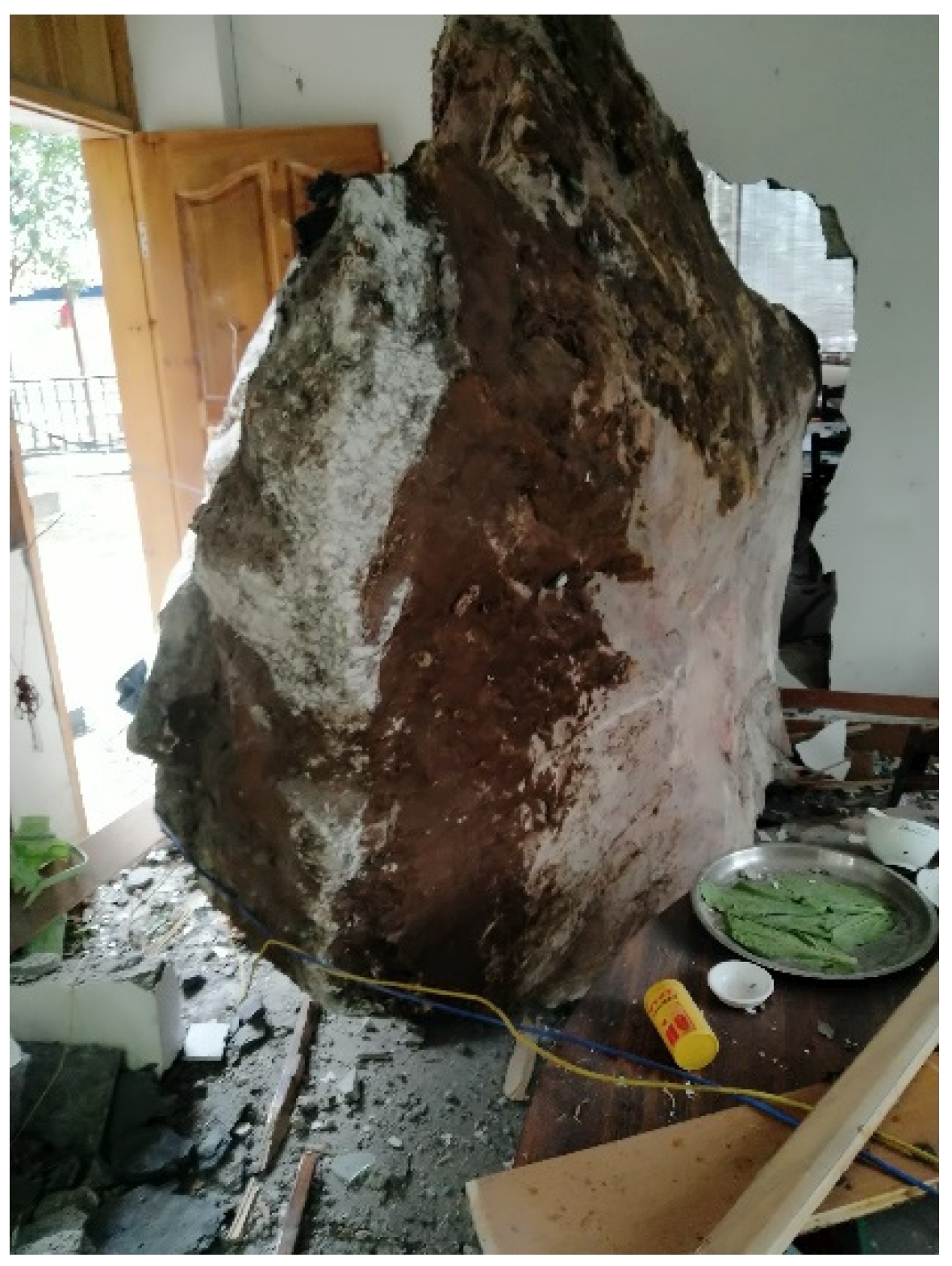
Figure 1. Rockfall into a residential building.
Preprints 94395 g001
Figure 2. Rockfall in Guilin Diecai Mountain.
Preprints 94395 g002
Figure 3. Model Experiment Device
Preprints 94395 g003
Figure 4. Schematic of 3-D Measurement for Arbitrary Shaped Rolling Rocks
Preprints 94395 g004
Figure 5. Test Blocks.
Preprints 94395 g005
Figure 6. Detailed Surface Roughness of the Slope.
Preprints 94395 g006
Figure 7. Block Rolling Speed at 30° Slope.
Preprints 94395 g007
Figure 8. Block Rolling Speed at 45° Slope.
Preprints 94395 g008
Figure 9. Block Rolling Speed at 60° Slope.
Preprints 94395 g009
Figure 10. Actual Rolling of Block G at a Height of 45 cm and 60° Slope.
Preprints 94395 g010
Figure 11. Actual Rolling of Block E at a Height of 45 cm and 60° Slope.
Preprints 94395 g011
Figure 12. Actual Rolling of Block D at a Height of 45 cm and 60° Slope.
Preprints 94395 g012
Figure 13. Actual Rolling of Block K at a Height of 45 cm and 60° Slope.
Preprints 94395 g013
Figure 14. Schematic Representation of Block Rolling.
Preprints 94395 g014
Figure 15. Illustration of Three Categories of Rock Scales [42].
Preprints 94395 g015
Figure 16. Schematic Illustration of Determining Rolling Distance and Damage Impact Range.
Preprints 94395 g016
Figure 17. Comparison of Rolling Speeds for a 30° Slope.
Preprints 94395 g017
Figure 18. Comparison of Rolling Speeds for a 45° Slope.
Preprints 94395 g018
Figure 19. Comparison of Rolling Speeds for a 60° Slope.
Preprints 94395 g019
Figure 20. Test block sways left and right during rolling.
Preprints 94395 g020
Figure 21. Block Rolling Without Swinging, Maintaining the Initial Rolling Axis.
Preprints 94395 g021
Figure 28. Variation of Rolling Resistance Arm δ as the Rolling Axis Changes.
Preprints 94395 g028
Figure 29. Comparison of Corrected Rolling Speeds for Block E on a 60° Slope.
Preprints 94395 g029
Figure 30. Comparison of Corrected Rolling Speeds for Block F on a 60° Slope.
Preprints 94395 g030
Figure 31. Schematic diagram for calculating rolling speed of composite slope and roughness.
Preprints 94395 g031
Table 1. Advantages and disadvantages of different research methods.
Method Advantage Disadvantage
Two-dimensional numerical simulation The trajectory (2D), velocity, impact energy and bounce height of the spherical rockfall can be calculated. It is assumed that the rockfall is a spherical particle without damage or deformation, and the influence of rockfall shape is not taken into account. [33]
Three-dimensional numerical simulation The shape, size and site characteristics of the rockfall can be restored to a high degree, and data such as the trajectory (3D), speed and energy of the rockfall can be obtained. [34] The accuracy of the simulation is affected by the accuracy of the three-dimensional modeling of the site, and the operation is complicated and the architecture and theoretical basis adopted by different software (models) are not uniform, so the simulation results obtained by different software (models) under the same conditions are different. [35]
Model test The experimental variables are controllable and the influence of various factors can be considered comprehensively. The established model has a wide range of application. The model test can not restore the actual rockfall disaster, and the empirical model is not reliable.
Data statistics The rockfall disaster data is the most realistic, and when the amount of data is sufficient, the reliability of the established model is higher. The empirical model is only applicable to the data source region or the region with similar topographic and geomorphologic characteristics.
Field test It can restore the rockfall disaster to the greatest extent, and the obtained data is closest to the real data, and the established empirical model has high reliability.
Table 2. Ingredients of C60 concrete grouting materials.
Materials Po52.5 Cement 8–20 Mesh Quartz Stone 20–80 Mesh Quartz Stone Fly Ash Silica Fume Water
Material Usage (%) 37 10 45 5 3 12.5
Additive ZY808 Defoamer ZY1100 Plastic Expansion Agent ZY8121 Water Reducing Agent MK400 Cellulose
Dosage per 100 kg (g) 30 20 130 15
Material Usage (%) 37 10 45 5
Table 3. Shape Parameters of Test Blocks.
Test Block Shape Size Test Block Mass (g)
Characteristic Length
A Sphere Diameter 70 449
B Regular Hexahedron Edge Length 56 432
C Regular Octahedron Edge Length 72 432
D Cylinder Diameter/Height 50/90 434
E Four-sided Prism ① Length/Width/Height 45/45/88 437
F Four-sided Prism ④ Length/Width/Height 50/55/64 440
G Octagonal Prism Edge Length/Height 20/90 427
H Dodecagonal Prism Edge Length/Height 13/91 423
I Hexagonal Disc Edge Length/Height 50/27 432
J Decagonal Disc Edge Length/Height 28/29 429
K Dodecagonal Disc Edge Length/Height 23/30 436
L Circular Disc Diameter/Height 90/28 437
Table 4. Calculation Parameters for Test Blocks.
Test Block λ R1´/R2´(mm) dk1/dk2 I1/I2
(×10-4)
ψ1/ψ2
A 1 35 1 2.2 0
B 1 40 0.9 2.29 0.36
C 1 50 0.9 2.28 0.34
D 0.56 25/51.5 1/0.87 1.38/5.74 0/0.44
E 0.51 31.8/49.4 0.90/0.86 1.5/3.63 0.36/0.48
F 0.86 37/40.6 0.9/0.89 2.03/2.61 0.36/0.38
G 0.59 26.1/52.3 0.97/0.71 1.2/5.9 0.1/0.45
H 0.55 25.1/52 0.99/0.69 1.12/5.78 0.06/0.44
I 0.27 50 0.96 4.11 0.17
J 0.31 47 0.95 4.06 0.13
K 0.34 44 0.99 4.09 0.04
L 0.31 45 1 4.51 0
Disclaimer/Publisher’s Note: The statements, opinions and data contained in all publications are solely those of the individual author(s) and contributor(s) and not of MDPI and/or the editor(s). MDPI and/or the editor(s) disclaim responsibility for any injury to people or property resulting from any ideas, methods, instructions or products referred to in the content.
Copyright: This open access article is published under a Creative Commons CC BY 4.0 license, which permit the free download, distribution, and reuse, provided that the author and preprint are cited in any reuse.
Prerpints.org logo

Preprints.org is a free preprint server supported by MDPI in Basel, Switzerland.

Subscribe

© 2024 MDPI (Basel, Switzerland) unless otherwise stated