Submitted:
26 December 2023
Posted:
26 December 2023
You are already at the latest version
Abstract
Keywords:
1. Introduction
2.1.1. Capillary limitation
2. Materials and Methods
2.1. Experimental set up
2.2. Experimental apparatus and procedure
3. Results
3.1. The comparison of heat transfer performance according to Cu powder type
3.2. Comparison of heat transfer performance according to sintered wick thickness and test angle
3.3. Comparison of heat transfer performance according to the working fluid filling ratio
3.4. Effect of the tilling angle on heat transfer performance
4. Conclusions
- (1)
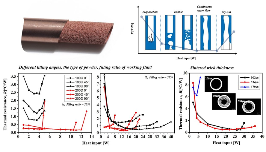
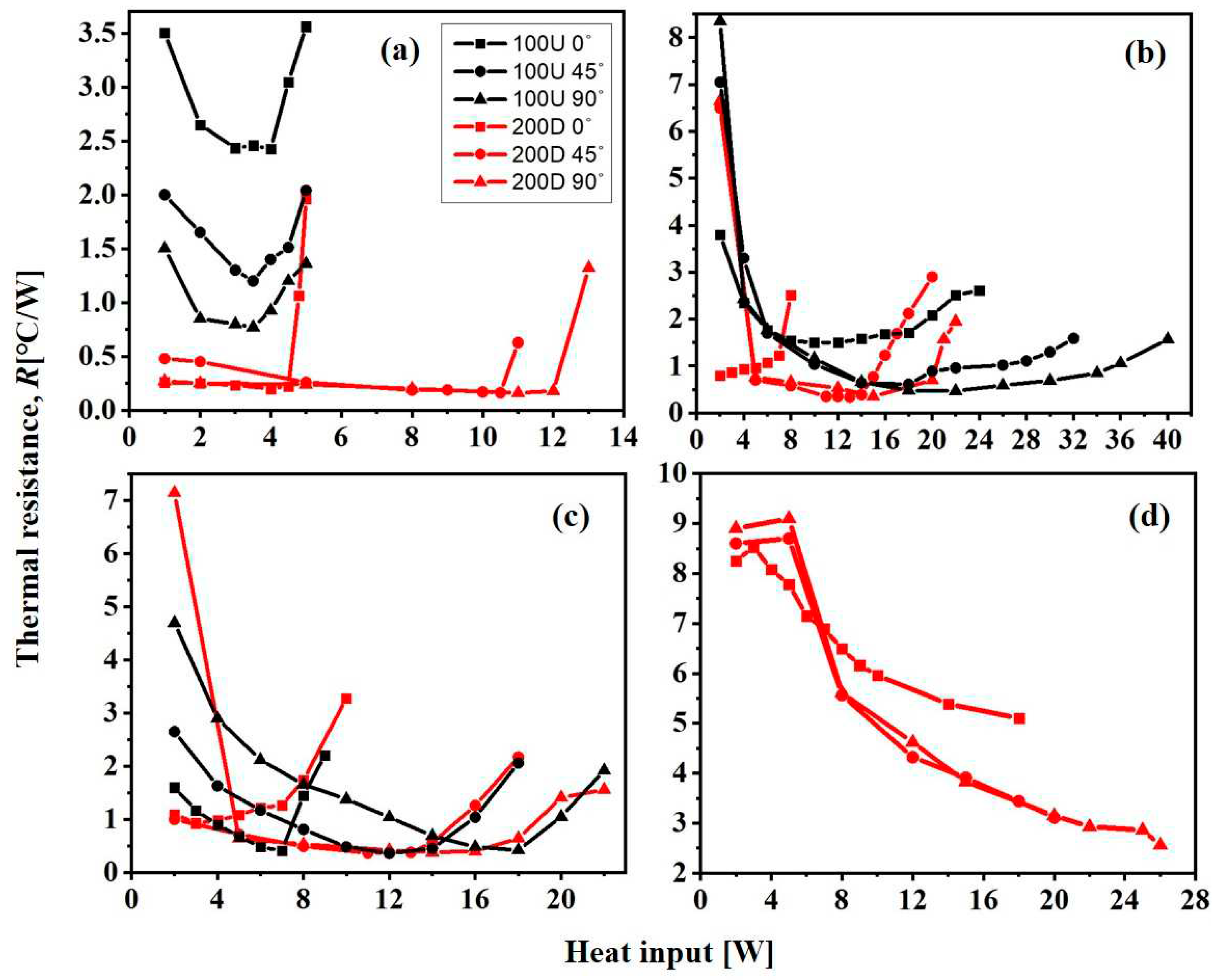
- The heat pipe, which was equipped with a sintered wick made from 200D powder, exhibited a smaller effective pore radius in comparison to 100U. As a result, the utilization of 200D powder resulted in an enhanced capillary force and exhibited improved efficacy in heat transfer.
- (2)
- The heat pipes' wick thicknesses were measured as 902μm, 534.7μm, and 179.1μm, which correspond to mandrel diameters of 1.5 mm, 2 mm, and 2.5 mm, respectively. The heat pipe, with a wick thickness of 534.7 ㎛, exhibited the most efficient heat transfer performance. The presence of a sufficient thickness of the wick ensures that an appropriate amount of working fluid is available to reach the region where evaporation takes place. Conversely, reducing the thickness of the wick results in a decrease in the amount of working fluid that can be retained in the wick, which can lead to dry-out, even when operating at low temperatures.
- (3)
- The initial thermal resistance value showed an increase as the filling ratio of the working fluid increased from 20wt.% to 50wt.%. Additionally, it was observed that the Qmax value exhibited a positive correlation with increasing temperature.
- (4)
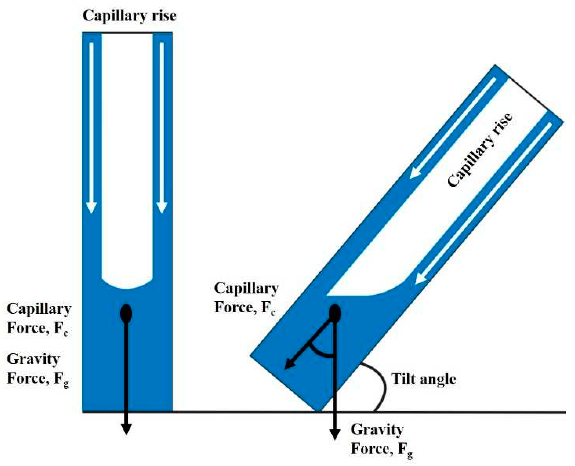
- The heat transfer performance shown an enhancement as the tilting angles increased within the range of 0˚to 90˚. This can be attributed to the enhanced thermal distribution by the gravity force, as well as the expansion of the surface area for heat transfer due to the enlarged cooling and heating surfaces. Consequently, the heat resistance exhibits a low value, whereas the Qmax exhibits a high value.
Funding
References
- Lee, W.H.; Lee, K.W.; Park, K.H.; Lee, K.J.; Noh, S.Y. In Study on a Operating Characteristics of Loop Heat Pipe Using a Brass Sintered Metal Wick-Water, Proceedings of the KSME Conference, The Korean Society of Mechanical Engineers: 2004; pp 1528-1533.
- Yun, H.G.; Moon, S.H.; Ko, S.C.; Hwang, G.; Choy, T.G. Manufacturing and operating performance of the heat pipe with sintered wick. Transactions of the Korean Society of Mechanical Engineers B 2002, 26, 1260–1266. [Google Scholar] [CrossRef]
- Jang, I.-N.; Ahn, Y.-S. The Study of Copper Powder Sintering for Porous Wick Structures with High Capillary Force. Materials 2023, 16, 4231. [Google Scholar] [CrossRef] [PubMed]
- Nezam, Z.Z.; Zohuri, B. Heat pipe as a passive cooling system driving new generation of nuclear power plants. Edelweiss Chemical Science Journal 2020, 3, 326. [Google Scholar] [CrossRef]
- Nemec, P.; Čaja, A.; Malcho, M. Mathematical model for heat transfer limitations of heat pipe. Mathematical Computer Modelling 2013, 57, 126–136. [Google Scholar] [CrossRef]
- Reay, D.; McGlen, R.; Kew, P. Heat pipes: theory, design and applications. Butterworth-Heinemann, 2013. [Google Scholar]
- Jiang, L.-l.; Yong, T.; Wei, Z.; Jiang, L.-z.; Tan, X.; Yan, L.; Gao, J.-w. Design and fabrication of sintered wick for miniature cylindrical heat pipe. Transactions of Nonferrous Metals Society of China 2014, 24, 292–301. [Google Scholar] [CrossRef]
- Esmaeilzadeh, A.; Silakhori, M.; Nik Ghazali, N.N.; Metselaar, H.S.C.; Bin Mamat, A.; Naghavi Sanjani, M.S.; Iranmanesh, S. Thermal performance and numerical simulation of the 1-pyrene carboxylic-acid functionalized graphene nanofluids in a sintered wick heat pipe. Energies 2020, 13, 6542. [Google Scholar] [CrossRef]
- Park, S.-Y.; Boo, J.-H. An Experimental Study on the Heat Transfer Characteristics of High-Temperature Cylindrical Heat Pipes. Korean Journal of Air-Conditioning and Refrigeration Engineering 2004, 16, 70–76. [Google Scholar]
- Vasiliev, L. Micro and miniature heat pipes–Electronic component coolers. J Applied Thermal Engineering 2008, 28, 266–273. [Google Scholar] [CrossRef]
- Li, Y.; He, J.; He, H.; Yan, Y.; Zeng, Z.; Li, B. Investigation of ultra-thin flattened heat pipes with sintered wick structure. Applied Thermal Engineering 2015, 86, 106–118. [Google Scholar] [CrossRef]
- Liao, X.; Jian, Q.; Zu, S.; Li, D.; Huang, Z. Visualization study and analysis on the heat transfer performance of an ultra-thin flat-plate heat pipe. International Communications in Heat Mass Transfer 2021, 126, 105464. [Google Scholar] [CrossRef]
- Datasheet, S. STM32H742xI/G STM32H743xI/G. 2019.
- Ilić, M.; Petrović, M.M.; Stevanović, V. Boiling heat transfer modelling a review and future prospectus. Thermal Science 2019, 23, 87–107. [Google Scholar] [CrossRef]
- Chang, C.; Han, Z.; He, X.; Wang, Z.; Ji, Y. 3D printed aluminum flat heat pipes with micro grooves for efficient thermal management of high power LEDs. Scientific reports 2021, 11, 8255. [Google Scholar] [CrossRef] [PubMed]
- Manimaran, R.; Palaniradja, K.; Alagumurthi, N.; Velmurugan, K. An investigation of thermal performance of heat pipe using Di-water. Sci Technol 2012, 2, 77–80. [Google Scholar] [CrossRef]
- Wang, G.; Quan, Z.; Zhao, Y.; Wang, H. Performance of a flat-plate micro heat pipe at different filling ratios and working fluids. Applied Thermal Engineering 2019, 146, 459–468. [Google Scholar] [CrossRef]
- Zhou, J.; Liu, L.; Yang, X.; Zhang, Y.; Wei, J. Visualization research on influencing factors of flat heat pipes. Applied Thermal Engineering 2022, 207, 118193. [Google Scholar] [CrossRef]
- Bamorovat Abadi, G.; Bahrami, M. A general form of capillary rise equation in micro-grooves. Scientific reports 2020, 10, 19709. [Google Scholar] [CrossRef] [PubMed]
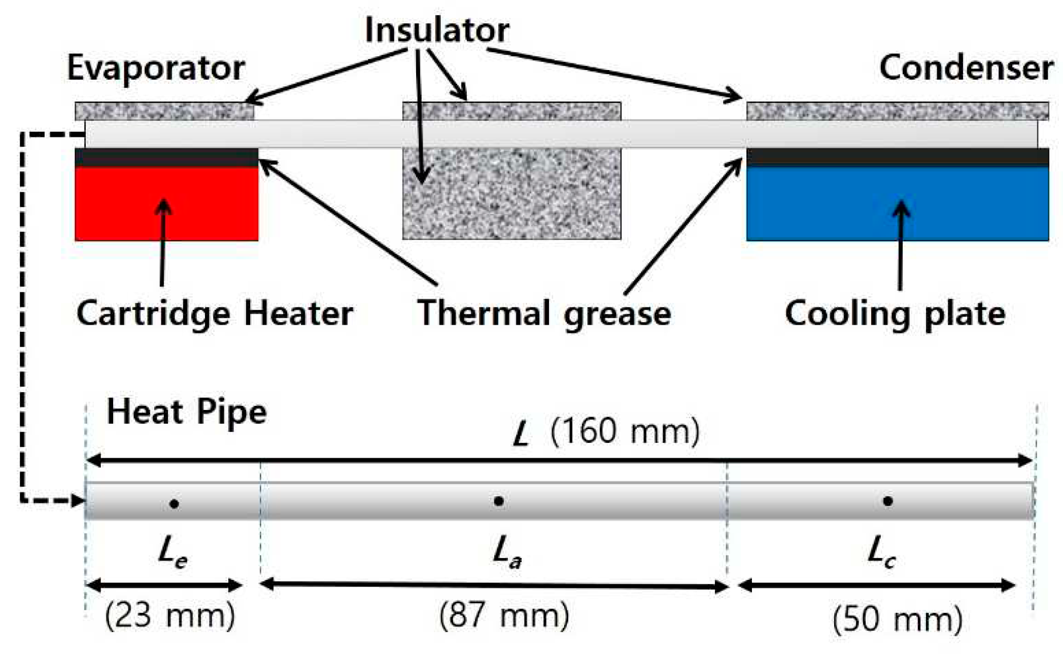


| Parameters | Value |
|---|---|
| Pipe material | Copper |
| Outer diameter of pipe, Dwall/㎜ | 4 |
| Inner diameter of pipe, Di/㎜ | 3.6 |
| Total length, L/㎜ | 160 |
| Evaporator length, Le/㎜ | 23 |
| Adiabatic length, La/㎜ | 87 |
| Condenser length, Lc/㎜ | 50 |
| Wick material | Copper powder |
| Spherical copper power size, d/㎛ | 100(Uniformity), 200(Diversity) |
| Wick thickness [㎛] | 902, 534, 179 |
| Working fluid | Distilled water |
| Filling ratio [% vol.] | 20(0.2g), 30(0.3g), 40(0.4g), 50(0.5g) |
Disclaimer/Publisher’s Note: The statements, opinions and data contained in all publications are solely those of the individual author(s) and contributor(s) and not of MDPI and/or the editor(s). MDPI and/or the editor(s) disclaim responsibility for any injury to people or property resulting from any ideas, methods, instructions or products referred to in the content. |
© 2023 by the authors. Licensee MDPI, Basel, Switzerland. This article is an open access article distributed under the terms and conditions of the Creative Commons Attribution (CC BY) license (http://creativecommons.org/licenses/by/4.0/).


