Introduction
Peltier cells consist of a set of p-n junctions grouped in series and parallel to increase voltage and current, encapsulated in a ceramic matrix to protect the junctions, to provide mechanical support, and to allow heat transfer from side to side. The number of p-n junction depends on the cell configuration and the manufacturing design, but they operate as a group with semiconductor characteristics [
1].
Peltier cells work in a reversible mode, either as an electric generator using a temperature gap between the two sides of the cell or as a thermal power source when injecting current at a specific voltage difference between the p and n sides of the junction [
2,
3]. Despite the ceramic material of the encapsulating body may stand for high temperatures, the Peltier cell cannot operate beyond a temperature limit because the welds of the p-n joints do not withstand temperatures above a specific threshold [
4,
5,
6]. On the other hand, if the temperature drops below a defined value, the cell efficiency reduces drastically, and the electric generation process becomes useless [
7,
8,
9,
10].
The current operating temperature range in commercial Peltier cells is -60º C to 320º C, although this range widens or shortens depending on the cell configuration [
11,
12,
13]. The efficiency of a Peltier cell depends on both the operating temperature and thermal gradient between the two sides of the cell, following a curve that reminds of a Gauss bell. This efficiency shape makes the cell to operate at optimum conditions in a narrow temperature difference margin around the peak power point, corresponding to a specific temperature [
14,
15].
Peltier cells suffer from a low efficiency because of the low existing temperature gap between hot and cold side of the cell [
16,
17]. This effect results from the heat transfer process across the cell due to the parallel thermal connection of the n and p semiconductor blocks [
1,
18].
The cold side of the Peltier cell must be cooled down using either an active external refrigeration source or a passive heat sink to avoid this problem [
19,
20]. An external refrigeration source produces a faster cooling but requires power for operation, reducing the global efficiency of the system. Passive heat sink cools down the cell slower but does not require an external power source. Nevertheless, it needs to evacuate the absorbed energy to avoid temperature rising, which reduces the cell temperature difference; thus, the efficiency.
We propose using a phase change materials (PCM) whose melting point matches the working temperature of the Peltier cells. The proposed PCM operates in biphasic mode, with the liquid section encapsulating the p-n junctions of the Peltier cell and the solid phase absorbing the heat flow from the cold side.
Theoretical Background
Peltier cells characterize by its electromotive force, which depends on the thermal gradient across the cell section and on the so called Seebeck coefficient representing the thermoelectric nature of the cell components [
21]; mathematically:
In which αAB is the Seebeck coefficient of the Peltier cell, with αA and αB the individual coefficients of the two elements of the Peltier cell p-n junction, e the cell thickness, the thermal gradient, and ∆T the temperature difference between the hot and cold side of the cell.
Although equation 1 shows an increasing value of electromotive force with thermal gradient, there is a limit of temperature operation because of the physical properties of the cell material [
22,
23,
24,
25,
26].
When Peltier cell plays the role of an electric generator, we should use the Peltier coefficient to obtain the power generation,
, as:
I represents the generated current, and π is the Peltier coefficient, with sub-indexes A and B accounting for the two cell components.
Peltier coefficient only depends on the kind of materials, while the generated current depends on the cell cross section [
27,
28,
29].
Peltier relates to Seebeck coefficients through the expression:
Equation 4 does not consider energy losses due to Joule’s effect and thermal conductivity; therefore, we should reformulate the Peltier cell power generation as:
κ and R are the two cell branches parallel thermal conductivity and series electric resistance .
Analyzing equation 5, we observe that thermal conductive material increases energy losses. Likewise, high electric resistance produces higher thermal losses due to Joule’s effect.
A further analysis shows that increasing the cell operating temperature also increases the power generation through the first term of equation 5; however, temperature difference raises too; thus, the power generation reduces. This analysis leads to an optimum operating conditions corresponding to a specific working temperature and thermal gradient.
Electric Generation
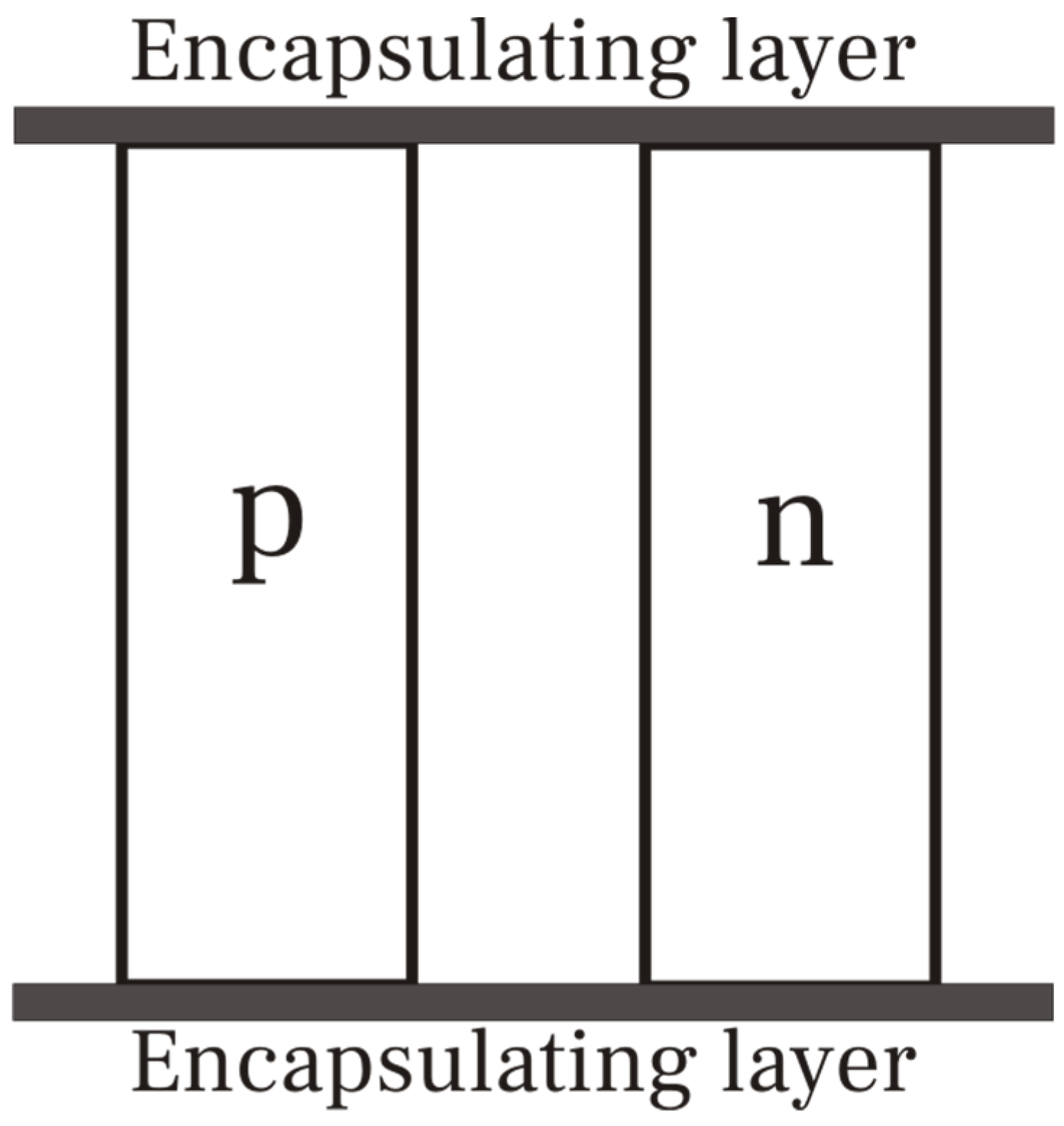
Peltier cell consists of a p-n junction encapsulated in a material, commonly ceramic, to maintain the cell structure (
Figure 1).
The power output of the realistic Peltier cell compared to an ideal configuration where the encapsulating layer does not exist is:
A is the cross section area of the Peltier cell, ρ is the electric resistivity and λ is the thermal conductivity. Sub-indexes o and c account for ideal configuration and encapsulating layer.
Provided we maintain the geometric configuration, parameters in equation 6 remain constant for specific p-n junction, but thermal conductivity and electric resistivity of the encapsulating layer, λc and ρc. To maximize the Pr ratio, we must increase ρc and reduce λc; nevertheless, if the case of ceramic as encapsulating material, the values depend only on the ceramic type, moving in a narrow margin. This situation limits the increase of Pr; therefore, the power generation.
Simulation
We may replace ceramic by another material of low thermal conductivity and high electric resistivity, which is the case of some PCM. Among the many existing phase change materials, we select the family of paraffin wax since they have a melting point compatible with the working temperature of Peltier cells.
Paraffin wax characterizes by a low thermal conductivity [
30,
31], which in current applications requires enhancement [
32,
33,
34,
35,
36,
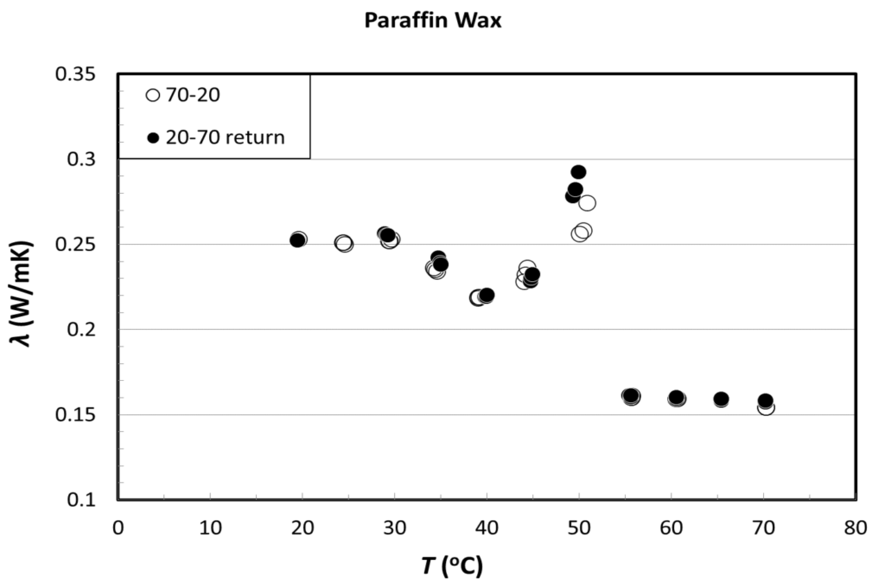
37]. Nevertheless in our case, low thermal conductivity increases power generation. Typical values of paraffin wax thermal conductivity are in 0.15 W/m·K to 0.25 W/m·K range, raising as melting temperature reduces (
Figure 2) [
38].We may replace ceramic by another material of low thermal conductivity and high electric resistivity, which is the case of some PCM. Among the many existing phase change materials, we select the family of paraffin wax since they have a melting point compatible with the working temperature of Peltier cells.
Paraffin wax characterizes as good electric insulator with high electric resistivity [
39] and excellent specific heat capacity [
40].
Since the paraffin wax is a composite material [
41,
42], melting point is not a single value but a range [
43,
44,
45], which depends on composition; it currently starts at 39º C [
46], although its most frequent melting temperature range is 46º C to 68º C [
47].
The above mentioned properties make paraffin wax as suitable element to encapsulate p-n junctions of a Peltier cell.
Table 1.
Properties of paraffin wax, ceramic material and Peltier cells [
48,
49,
50].
Table 1.
Properties of paraffin wax, ceramic material and Peltier cells [
48,
49,
50].
| Property |
Paraffin wax |
Ceramic |
Peltier cell |
| Thermal conductivity (W/m·K) |
0.2 |
2.5 |
1.55 |
| Electric resistivity (Ω·m) (x1017) |
1.0 |
7.5 |
2.8 |
We consider the following thicknesses (
Table 2) to evaluate the power generation gain.
Using data from literature (
Table 1) and applying equation 6, for we have:
Equation 7 shows that power ratio raises by a factor of 2 by reducing the encapsulating layer electric and thermal conductivity.
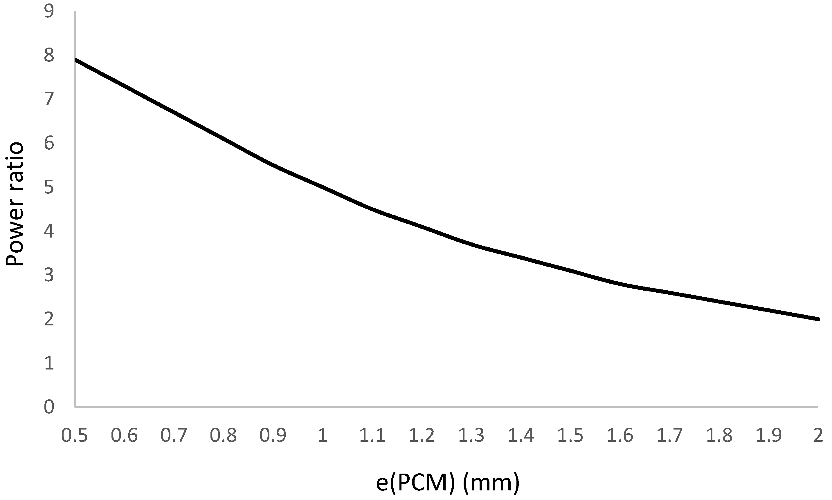
Power ratio gain is very sensitive to the PCM layer thickness, which encapsulates the p-n junctions. This thickness depends on the thermal gradient, operating temperature and diffusion process that evacuates the heat flow across the cell. To determine the influence of the layer thickness, we extend the simulation to a range from 0.5 mm to 2.0 mm. Simulation results are in
Figure 3.
We observe that encapsulating body layer thickness significantly influences the power generation ratio, increasing it to a factor of 5 for a PCM layer thickness one-fourth of the ceramic body thickness.
Power generation ratio matches a second degree polynomial function of the type:
δ is the layer thickness.
Heat Transfer
The layer thickness of the PCM, which encapsulates the p-n junctions, depends on thermal balance at the PCM fluid phase and the heat exchange with its solid phase. Since the heat transfer across the PCM layer produces by conduction, we have
κ, e and S are the thermal conductivity, thickness and cross section of the PCM layer, respectively, and ΔTc is the temperature difference between hot and cold side of the cell.
Heat flow,
, should match the absorbed energy in the PCM encapsulating layer during the transient state,
Δt, which corresponds to the liquefied section of the PCM bulk; therefore:
c, L and ρ correspond to the specific heat, latent heat and density of the phase change material. To and Tmp are the initial and melting point temperature of the PCM.
Combining equations 9 and 10:
T is the temperature of the PCM, with sub-indexes H and mp accounting for the hot side and melting point.
Considering the encapsulating layer is symmetric respect to the p-n junction set, we can determine the layer thickness as
Equation 13 provides the algorithm to calculate the layer thickness corresponding to the simulation.
Because thermal conductivity, latent heat and density of the PCM are well-known constants [
30,
31,
38,
51,
52], considering that the p-n junction set has a specific thickness, the layer thickness only depends on the hot side and initial temperature.
Layer Thickness
The simulation continues with the encapsulating layer thickness determination for transient time interval from 1 to 6 minutes and cell temperature gap between 50º C and 100º C.
Table 3 shows the simulation results.
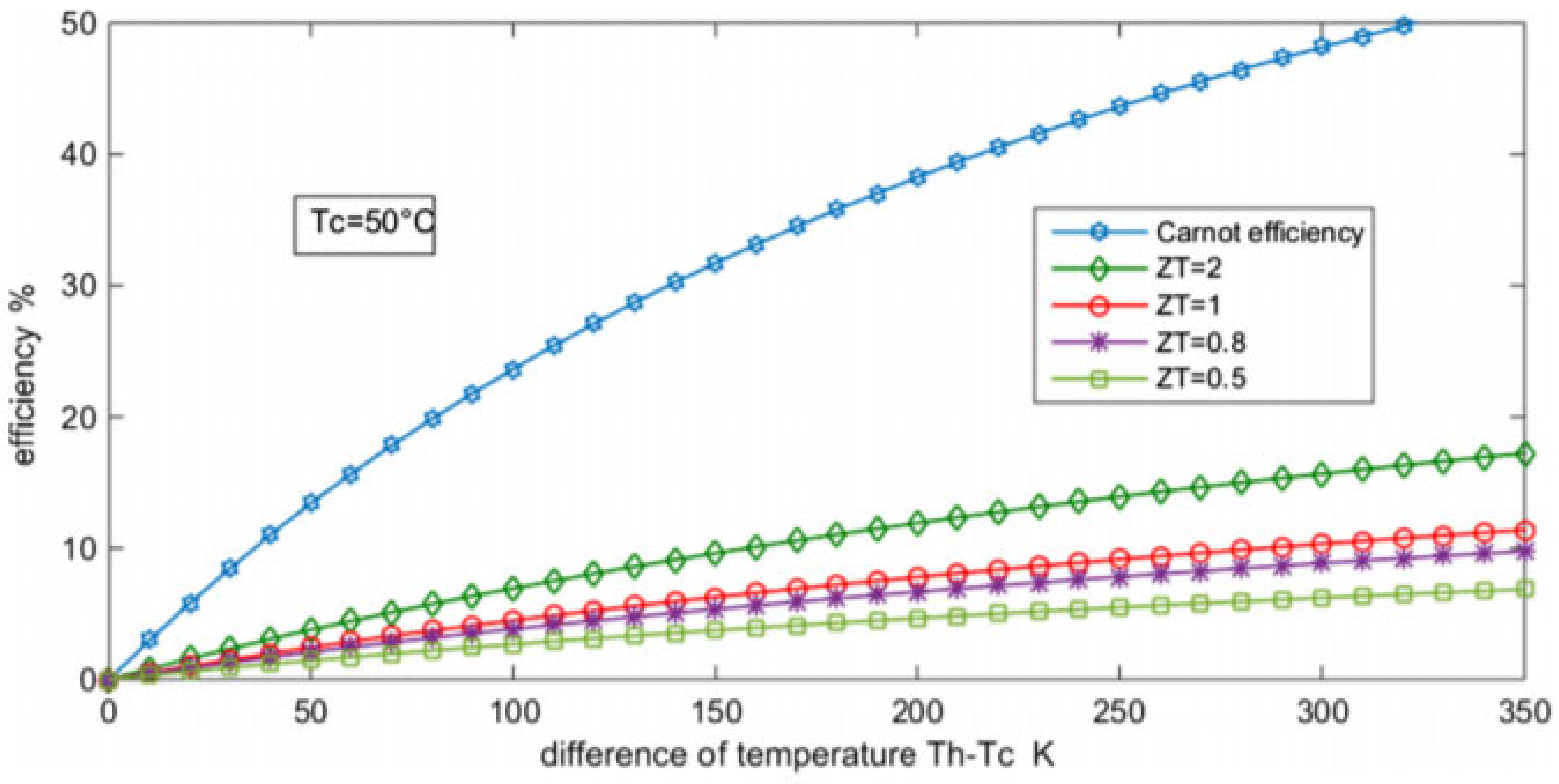
Retrieving the efficiency evolution with temperature gap for Peltier cells (
Figure 3), we can determine the power generation ratio for the simulated operating conditions.
Since the Peltier cell efficiency depends on the temperature difference and the so called “Figure of Merit”, we should determine this parameter to select the appropriate curve on
Figure 3.
The Peltier cell figure of merit describes the quality of a thermoelectric generator (TEG) and characterizes by a factor that relates to the ideality of a Carnot cycle. The mathematical expression of the Figure of merit,
Z, is:
κ and ρ account for thermal conductivity and electric resistivity, and α is the Seebeck coefficient.
Applying data for our Peltier cell, we have Z=1.27
Figure 4.
Peltier cell efficiency vs. temperature gap [
53].
Figure 4.
Peltier cell efficiency vs. temperature gap [
53].
Operating in a temperature difference range from 50º C to 140º C, which are the limits of our case, we can adjust the efficiency curve to a linear function of the type:
With the temperature in centigrade
Power Generation
Peltier cell power generation depends on different parameters: temperature gap across the cell, encapsulating layer thickness and operating temperature. To evaluate the Peltier cell output power, we consider the combined effects of the three mentioned parameters according to the simulation results previously developed. Nevertheless, the power generation also depends on the transient time since the Peltier cell temperature gap evolves with time from the initial to the steady state; therefore, we also consider the transient time as a parameter that influences the power generation and the power generation ratio.
We obtain the following results combining all mentioned parameters (
Figure 5).
We observe that power generation increases with raising temperature gap and with transient time decrease; the evolution of power generation follows, in all cases, a second degree polynomial function with coefficients
a, b and
c listed in
Table 4 for the different cases.
With the exception of the curve corresponding to the 2 minutes transient time that shows an adjusting coefficient of 91%, the fitting to the second polynomial curve is higher than 94% with regression coefficient near 100% in 50% of the cases; therefore, we can predict the Peltier cell power generation provided we know the temperature gap and the transient time with high accuracy.
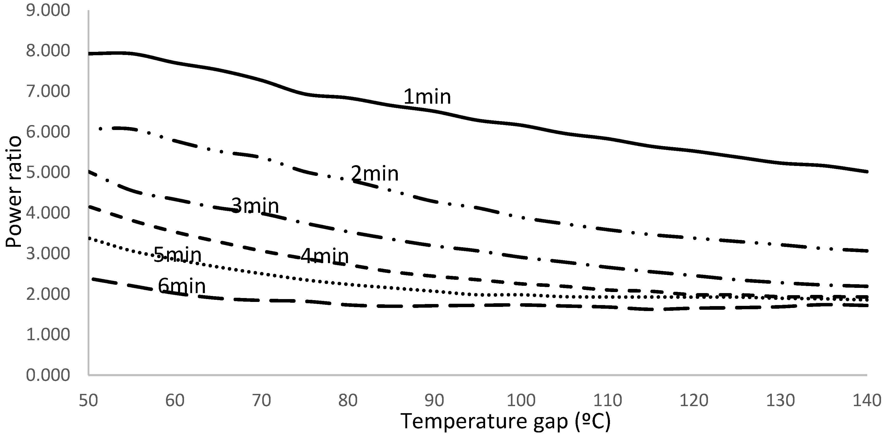
The analysis of simulation results shows that power generation increases by a factor between 1.625 and 7.930, as shown in
Figure 6.
Power generation and power ratio increases with reducing layer thickness for identical temperature gap. For every layer thickness, power ratio decreases with temperature gap increase in opposition to power generation, which increases as temperature gap does.
Experimental Tests
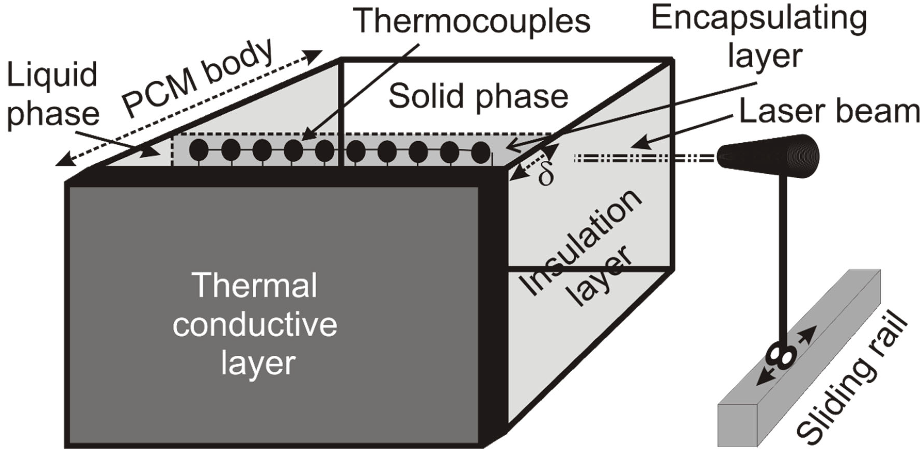
To validate the simulation results, we build a prototype consisting in a PCM matrix encapsulating a 127 p-n junction set, configuring the prototype Peltier cell. A thin thermal conductive film of 0.05 mm thickness covers the hot side of the cell. Thermal insulation film covers upper and bottom edge, and left and right side of the matrix (
Figure 7).
We insert the prototype cell in a parallelepiped hermetic closed chamber of insulation material, building a hole of equal size that the prototype cell cross section in the chamber rear wall where we incrust the prototype cell. Front side of the cell prototype, corresponding to the thermal conductive layer, heats from a commercial heating source that blows hot air inside the chamber at a temperature up to 160º C. Temperature is controlled by a thermistor thermostat of ±1º C.
A power analyzer PCE-PW6000 A measures and registers the cell voltage and current, determining power within 1% accuracy. Encapsulating layer thickness is measured using a laser beam which moves sideways from front to back on a graduated sliding rail of 0.1 mm precision. Laser beam width is less than 0.05 mm. We measure the encapsulating layer thickness through the changes in laser beam intensity because of the PCM liquid and solid phase different refraction coefficient.
Tests run for temperature gap from 50º C to 140º C. To control temperature, we use T-thermocouples of 0.5º K accuracy. Cold side of the cell maintains at constant ambient temperature (20º C) due to the solid phase, which plays the role of a heat sink. If temperature raises, a heat exchanger inserted in the solid phase bulk evacuates the excess of energy and keeps the solid phase temperature within limits.
Transient state time modifies changing the hot air flow from the heating source; indeed, applying energy balance, we have:
is the air flow in the chamber, c is the specific heat, FR is the heat transfer coefficient through from air to PCM, is the PCM mass in liquid phase, ttr is the transient time, and T is the temperature, with sub-indexes in and out accounting for the air at the chamber inlet and outlet duct, o for the initial temperature of the PCM, which currently matches the ambient, and the melting point PCM temperature.
Since we measure temperatures and air flow in the chamber, and because we know specific heat of air and PCM, and the PCM liquid phase mass, solving for equation 15, we have:
Assuming the dependence on temperature is negligible or of low significance for specific heat of PCM and air, we consider these two parameters remain unchanged during operation. Since PCM is in thermal equilibrium with the ambient before starting the test, and because PCM melting point is fixed, To and remain constant too. Liquid phase PCM mass and heat transfer coefficient are also constant, provided we neglect variations of FR with temperature, which are small for the operating range.
The above considerations make the transient time only dependent on heating air flow mass and temperature gap inside the chamber. Since these two parameters depend on each other through the expression:
FL represents the thermal losses factor in transferring energy from the external heating source to the air chamber.
We run a test measuring air flow temperatures before and after the external heating source and chamber inlet and outlet temperature to determine
FL value. Mathematically:
If we know the external source heating power, , and if we measure the air flow inlet and outlet temperature, the mass flow is set up.
We, therefore, can convert equation 17 into:
Since the numerator remains constant over the test duration, transient time only depends on the external heating power source; changing the power modifies the transient time; this is how to set up ttr value.
We sets up hot side temperature using the thermal balance of air flow from the external heating source; considering a linear evolution of air temperature inside the chamber, which is highly accurate, we establish:
We determine the cell prototype hot side temperature by regulating the heating power and air flow and measuring outlet temperature at the air chamber.
The layer thickness value results applying equation 13, where thermal conductivity, specific heat, density, latent heat and melting point temperature of the PCM are known. To determine cell hot side temperature, we apply equation 21. Thickness of the thermocouple (p-n junction) comes from the manufacturer datasheet. Initial temperature matches ambient one, and time interval is the transient time determined using equation 20.
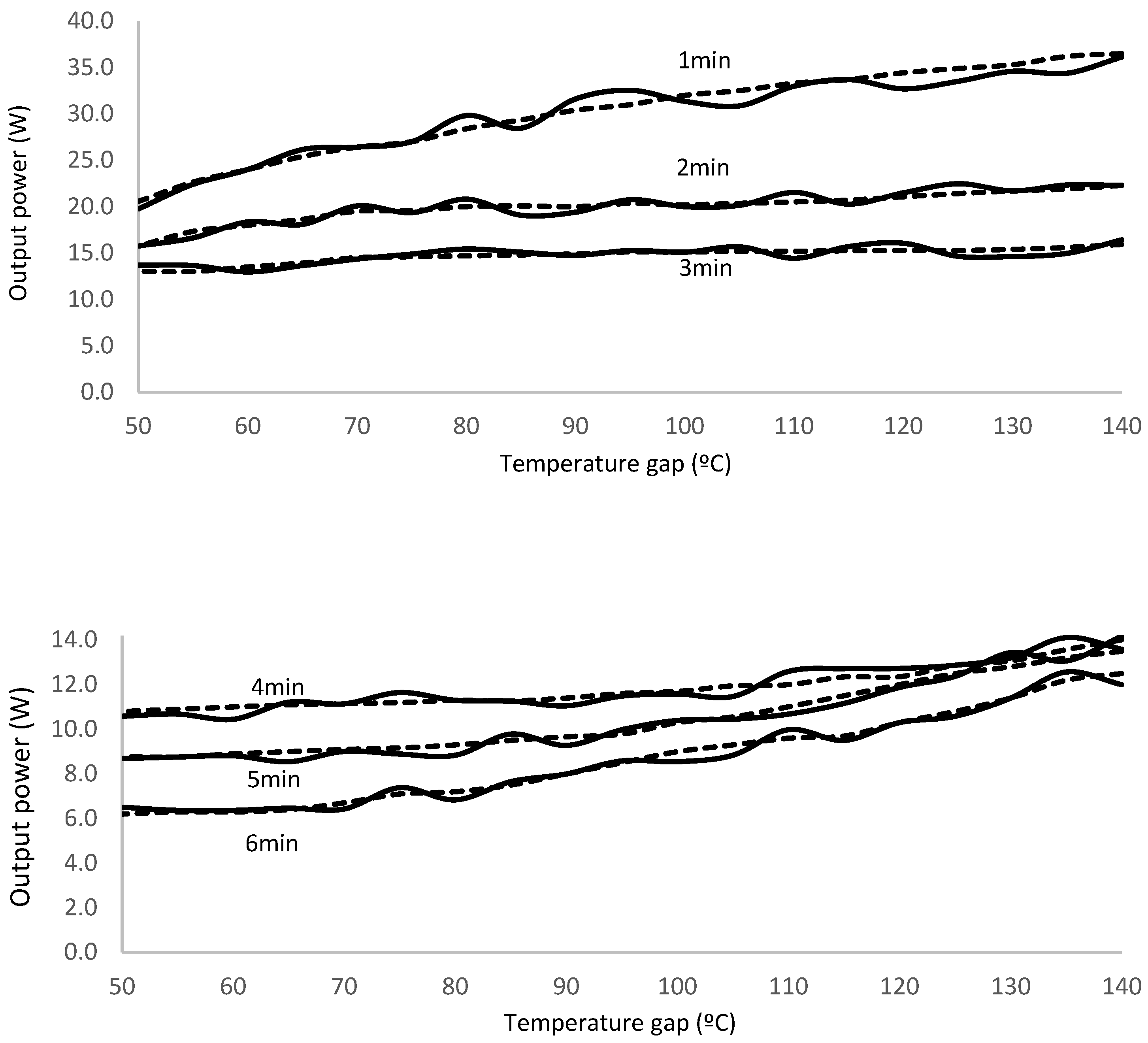
Experimental results show in
Figure 8. To facilitate the viewing, we split the results in two graphs, first for tests corresponding to transient time between 1 and 3 minutes and second for 4 to 6 minutes.
We realize that experimental results match theoretical simulation data within 95% accuracy, thus validating the proposed methodology to evaluate the output power for the Peltier cell prototype.
We also notice that output power tends to merge for high transient times, 4 to 6 minutes, as the temperature gap increases; however, for low transient times, 1 to 3 minutes, it separates.
Conclusions
We design and build a new Peltier cell with the thermocouples encapsulated in a PCM matrix. The new prototype shows higher output power with regarding conventional Peltier cell structure with ceramic encapsulating material.
Power generation ratio of new prototype to conventional model is in the range 1.625 to 7.930 depending on the temperature gap between the cell sides and on the transient time to reach the steady state operating temperature. The greater the temperature gap, the lower the power generation ratio. On the other hand, the shorter the transient time, the higher the power generation ratio.
We demonstrate that regulating operational conditions we may change the PCM encapsulating layer thickness. New Peltier cell prototype performance also depends on the layer thickness; the wider the layer, the poorer the performance. Typical thickness develops from 0.5 mm for temperature gap of 50º C at 1 minute transient time to 2.9 mm for temperature difference of 140º C at 6 minutes transient time.
PCM encapsulating layer thickness greatly influences the Peltier cell power generation, with values from a minimum of 7.2 W for maximum transient time and minimum temperature gap to maximum of 36.5 W form minimum transient time and maximum temperature gap.
Run experimental tests at different operating conditions show matching values with theoretical simulation results within 95% accuracy. Temperature difference for the operating conditions is in the 50º C to 140º C range.
Power generation increases with temperature gap for every transient time; however, it reduces if the transient time increases. Output power tends to merge for high transient times, 4 to 6 minutes, as the temperature gap increases; however, for low transient times, 1 to 3 minutes, it separates.
References
- CRC Handbook of Thermoelectrics. Edited by D.M. Rowe. CRC Press. 1995.
- In, T.E.C. Measurement of characteristics of a Peltier cell.
- Brestovič, T.; Jasminska, N.; Čarnogurská, M.; Puškár, M.; Kelemen, M.; Fiľo, M. Measuring of thermal characteristics for Peltier thermopile using calorimetric method. Measurement 2014, 53, 40–48. [Google Scholar] [CrossRef]
- Thomson, W. 4. on a mechanical theory of thermo-electric currents. Proceedings of the Royal society of Edinburgh 1857, 3, 91–98. [Google Scholar] [CrossRef]
- Lodge, O.J. XX. On the seat of the electromotive forces in the voltaic cell: To the editors of the Philosophical Magazine and Journal. The London, Edinburgh, and Dublin Philosophical Magazine and Journal of Science 1885, 19, 153–190. [Google Scholar] [CrossRef]
- Lampinen, M.J. Thermodynamic analysis of thermoelectric generator. Journal of applied physics 1991, 69, 4318–4323. [Google Scholar] [CrossRef]
- Troxler, Y.; Wu, B.; Marinescu, M.; Yufit, V.; Patel, Y.; Marquis, A.J.; Offer, G.J. The effect of thermal gradients on the performance of lithium-ion batteries. Journal of Power Sources 2014, 247, 1018–1025. [Google Scholar] [CrossRef]
- Freire, L.O.; Navarrete, L.M.; Corrales, B.P.; Castillo, J.N. Efficiency in thermoelectric generators based on Peltier cells. Energy Reports 2021, 7, 355–361. [Google Scholar] [CrossRef]
- Kumar, S.; Mahto, D. Thermal Analysis and Performance Evaluation of Peltier Module. In Renewable Energy and its Innovative Technologies: Proceedings of ICEMIT 2017, Volume 1; Springer: Singapore, 2019; pp. 173–184. [Google Scholar]
- Ding, L.C.; Akbarzadeh, A.; Date, A.J.A.T.E. Performance and reliability of commercially available thermoelectric cells for power generation. Applied Thermal Engineering 2016, 102, 548–556. [Google Scholar] [CrossRef]
- Your Thermoelectric Partner. TEG Installation. Custom Thermoelectric LLC. 11941 Industrial Park Road, Suite 5 | Bishopville, MD 21813.
- Peltier cell TEC 1-127 10HTS. http://descargas.cetronic.es/TEC1-12710.pdf [Accessed online: 18/12/2023].
- Temperature control for MCR: Peltier systems. Anton Paar. https://www.anton-paar.com/uk-en/products/details/temperature-control-peltier-systems-40-oc-to-200-oc/#:~:text=Peltier%20temperature%20devices%20for%20cone,C%20and%20220%20%C2%B0C. [Accessed online: 18/12/2023].
- Armenta-Déu, C. Hybrid PV-TEG system to improve performance. International Journal of Microwave Engineering and Technology 2022, 9, 1–18. [Google Scholar]
- Armenta-Déu, C. Hybrid TEG System for Industrial and Air Conditioning Applications. Journal of Refrigeration, Air Conditioning, Heating and Ventilation 2022, 9, 1–17. [Google Scholar] [CrossRef]
- Singh, B. The effects of temperature difference and compressive force to the electrical characterization of peltier cell for artificial concentrated solar power thermoelectric application. Journal of Mechanical Engineering (JMechE) 2014, 11, 15–30. [Google Scholar]
- Peltier TEC Devices. https://www.cuidevices.com/catalog/thermal-management/peltier-devices [Accessed online: 18/12/2023].
- How is heat transferred in a Peltier/Thermoelectric module?. Applied Thermoelectric Solutions. https://thermoelectricsolutions.com/how-is-heat-transferred-peltier-module/ [Accessed online: 18/12/2023].
- Gragnaniello, L.; Iasiello, M.; Mauro, G.M. Multi-Objective optimization of a heat sink for the thermal management of a peltier-cell-based biomedical refrigerator. Energies 2022, 15, 7352. [Google Scholar] [CrossRef]
- Armenta-Déu, C. PV Panel Efficiency Improvement Using a Hybrid PV-TEG Assembly System. International Journal of Embedded Systems and Emerging Technologies 2021, 7, 1226. [Google Scholar] [CrossRef]
- Energy conversion devices. Peltier modules [Thermoelectric modules]. Basic structure. KYOCERA Global. Peltier module (Thermoelectric module) - Energy Conversion Devices - KYOCERA [Accessed online: 22/12/2022].
- Caswell, A.E. Determination of Peltier Electromotive Force for Several Metals by Compensation Methods. Physical Review (Series I) 1911, 33, 379. [Google Scholar] [CrossRef]
- Amezawa, K.; Yamamoto, N.; Tomii, Y.; Ito, Y. Thermodynamic Properties and Single-Electrode Peltier Heats of a Li-Al Alloy in a LiCl-KCl Eutectic Melt. Journal of The Electrochemical Society 1999, 146, 1069. [Google Scholar] [CrossRef]
- Wittrock, H.J. (1949). The Electromotive Force and Current Density of the Copper-copper Sulfate Thermocell. University of Wisconsin--Madison.
- Hansen, E.M.; Egner, E.; Kjelstrup, S. Peltier effects in electrode carbon. Metallurgical and Materials Transactions B 1998, 29, 69–76. [Google Scholar] [CrossRef]
- Chukwu, G.U. Thermoelectric Study of Peltier Effect Using Cu-Fe, Pb-Fe and Cu-Constantan Couples. International Journal of Innovative Scientific & Engineering Technologies Research 2016, 4, 1–12. [Google Scholar]
- Freire, L.O.; Navarrete, L.M.; Corrales, B.P.; Castillo, J.N. Efficiency in thermoelectric generators based on Peltier cells. Energy Reports 2021, 7, 355–361. [Google Scholar] [CrossRef]
- Mannella, G.A.; La Carrubba, V.; Brucato, V. Peltier cells as temperature control elements: Experimental characterization and modeling. Applied thermal engineering 2014, 63, 234–245. [Google Scholar] [CrossRef]
- Mardini-Bovea, J.; Torres-Díaz, G.; Sabau, M.; De-la-Hoz-Franco, E.; Niño-Moreno, J.; Pacheco-Torres, P.J. A review to refrigeration with thermoelectric energy based on the Peltier effect. Dyna 2019, 86, 9–18. [Google Scholar] [CrossRef]
- Ukrainczyk, N.; Kurajica, S.; Šipušić, J. Thermophysical comparison of five commercial paraffin waxes as latent heat storage materials. Chemical and biochemical engineering quarterly 2010, 24, 129–137. [Google Scholar] [CrossRef]
- Raza, G.; Iqbal, S.; Farooq, A.S. (2021). Paraffin Wax-Based Thermal Composites. In Paraffin-Thermal Energy Storage Applications. IntechOpen.
- Kumar, P.M.; Anandkumar, R.; Mylsamy, K.; Prakash, K.B. Experimental investigation on thermal conductivity of nanoparticle dispersed paraffin (NDP). Materials Today: Proceedings 2021, 45, 735–739. [Google Scholar]
- Mettawee, E.B.S.; Assassa, G.M. Thermal conductivity enhancement in a latent heat storage system. Solar energy 2007, 81, 839–845. [Google Scholar] [CrossRef]
- Xu, X.; Zhang, X.; Ji, J.; Fang, M.; Yang, M.; Ma, K.; Gao, Y. Comparative Analysis of Additives for Increasing Thermal Conductivity of Phase Change Materials: A Review. Energy & Fuels 2022, 36, 5088–5101. [Google Scholar]
- George, M.; Pandey, A.K.; Abd Rahim, N.; Tyagi, V.V.; Shahabuddin, S.; Saidur, R. A novel polyaniline (PANI)/paraffin wax nano composite phase change material: Superior transition heat storage capacity, thermal conductivity and thermal reliability. Solar Energy 2020, 204, 448–458. [Google Scholar] [CrossRef]
- M. Usman, F. Siddiqui, A. Ehsan, R.A. Sadaqat and A. Hussain, "Improvement of thermal conductivity of paraffin wax, a phase change material with graphite powder," 2020 17th International Bhurban Conference on Applied Sciences and Technology (IBCAST), Islamabad, Pakistan, 2020, pp. 16–25. [CrossRef]
- Leong, K.Y.; Hasbi, S.; Ahmad, K.K.; Jali, N.M.; Ong, H.C.; Din, M.M. Thermal properties evaluation of paraffin wax enhanced with carbon nanotubes as latent heat thermal energy storage. Journal of Energy Storage 2022, 52, 105027. [Google Scholar] [CrossRef]
- Conductividad térmicas durante el cambio de fase de materiales (PCM). Thermtest Instruments. Latin America. Iberá 2990, CP C1428CMT, Buenos Aires, Argentina. www.thermtest.com/latinamerica.
- "Electrical insulating materials". Kaye and Laby Tables of Physical and Chemical Constants. National Physical Laboratory. 1995. Archived from the original on 27 September 2007. Retrieved 25 October 2013.
- "Specific Heat Capacity". Diracdelta.co.uk Science and Engineering Encyclopedia. Dirac Delta Consultants Ltd, Warwick, England. Archived from the original on 4 August 2007. Retrieved 25 October 2013.
- Ferris, S.W.; Cowles, H.C.; Henderson, L.M. Composition of paraffin wax. Industrial & Engineering Chemistry 1929, 21, 1090–1092. [Google Scholar]
- Kousksou, T.; Jamil, A.; El Rhafiki, T.; Zeraouli, Y. Paraffin wax mixtures as phase change materials. Solar Energy Materials and Solar Cells 2010, 94, 2158–2165. [Google Scholar] [CrossRef]
- Turner, W.R.; Brown, D.S.; Harrison, D.V. Properties of paraffin waxes. Industrial & Engineering Chemistry 1955, 47, 1219–1226. [Google Scholar]
- ICSC 1457 Paraffin Wax. International Labour Organization. http://www.ilo.org/dyn/icsc/showcard.display?p_card_id=1457&p_version=2&p_lang=en [Accessed online: 19/12/2023].
- Paraffin Wax. Chemical Book. CAS Database List. Paraffin Wax Properties. https://www.chemicalbook.com/ChemicalProductProperty_EN_CB2854418.htm [Accessed online: 19/12/2023].
- Freund, M.; Mózes, G. In Paraffin products: Properties, technologies, applications; Jakab, E., Translator; Elsevier: Amsterdam, the Netherlands, 1982; p. 121. ISBN 978-0-444-99712-8. [Google Scholar]
- Nasser, William E (1999). "Waxes, Natural and Synthetic". In McKetta, John J (ed.). Encyclopedia of Chemical Processing and Design. Vol. 67. New York: Marcel Dekker. p. 17. ISBN 978-0-8247-2618-8.
- J. Morillas López (2015) Microfisuración de entallas en cerámicas mediante mecanizado por ablación con pulsos láser ultra cortos. Anejo A: Propiedades térmicas de los materiales cerámicos.
- Tabla de resistividad eléctrica. Waxasoftware. http://www.vaxasoftware.com/doc_edu/fis/resistividad.pdf [Accessed online: 19/12/2023].
- In, T.E.C. Measurement of characteristics of a Peltier cell.
- Oliver, A.; Neila, F.J.; García-Santos, A. PCM choosing and classification according to their characteristics for their application for thermal energy storage systems. Technical Note. Materiales de Construcción 2010, 62, 131–140. [Google Scholar] [CrossRef]
- Security datasheet for paraffin wax. Article number 9279. Version 1.0 es. Carl Roth Gmbh + Co KG. Emission date: 19/01/2017.
- C. Armenta-Déu (2023) Design of a Thermoelectric Generator System for coupling in Air Conditioning Equipment. Energies (under review).
|
Disclaimer/Publisher’s Note: The statements, opinions and data contained in all publications are solely those of the individual author(s) and contributor(s) and not of MDPI and/or the editor(s). MDPI and/or the editor(s) disclaim responsibility for any injury to people or property resulting from any ideas, methods, instructions or products referred to in the content. |
© 2023 by the authors. Licensee MDPI, Basel, Switzerland. This article is an open access article distributed under the terms and conditions of the Creative Commons Attribution (CC BY) license (http://creativecommons.org/licenses/by/4.0/).
