Submitted:
27 December 2023
Posted:
28 December 2023
You are already at the latest version
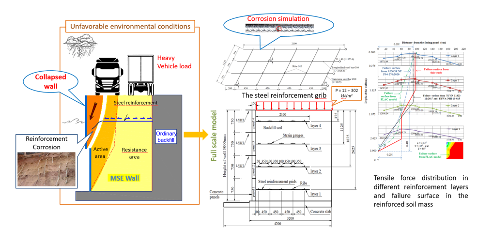
Abstract
Keywords:
1. Introduction
2. Full-scale experimental model
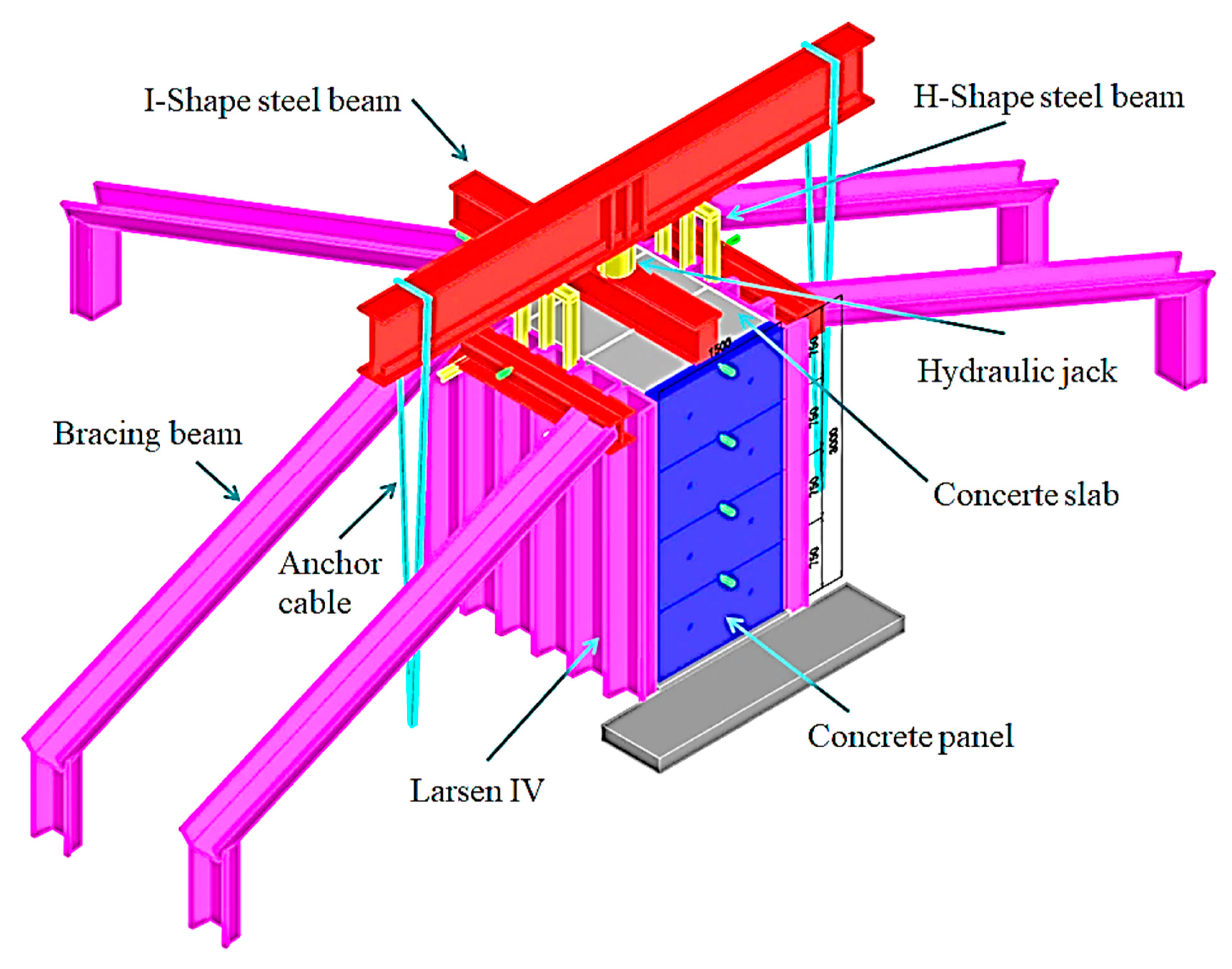
2.1. Model Design
2.2. Construction and instrumentation of the MSE wall
3. Numerical modelling
f*= tanϕ
f*=fo*(1-z/zo)+(z/zo)tanϕ
4. Results and discussion
4.1. Full-scale model results


4.2. Numerical model results
5. Conclusions
Author Contributions
Data Availability Statement
Acknowledge
Conflicts of Interest
Notations
References
- Berg, R., Christopher, B., Samtani, N. "Design of Mechanically Stabilized Earth Walls and Reinforced Soil Slopes." edited by Volume II: Federal Highway Administration (FHWA), Washington, DC, 2009.
- Chang, J. C., Forsyth, R., Smith, T. "Reinforced Earth Highway Embankment-Road 39." Highway Focus 4, no. 1 (1972): 15-35.
- Chau, T.-L., Nguyen, T.-H., Vu, D.-P. "A Study on the Main Factors Affecting the Reinforcement Corrosion in Mechanically Stabilised Earth Walls and Predict the Service Life of the Wall." Paper presented at the CIGOS 2021, Emerging Technologies and Applications for Green Infrastructure: Proceedings of the 6th International Conference on Geotechnics, Civil Engineering and Structures. 2022.
- Khan, B. J., Ahmad, M., Sabri, M. M. S., Ahmad, I., Zamin, B., Niekurzak, M. "Experimental and Numerical Evaluation of Mechanically Stabilized Earth Wall with Deformed Steel Bars Embedded in Tire Shred-Sand Mixture." Buildings 12, no. 5 (2022): 548. [CrossRef]
- Ahmadi, H., Bezuijen, A. "Full-Scale Mechanically Stabilized Earth (Mse) Walls under Strip Footing Load." Geotextiles and Geomembranes 46, no. 3 (2018): 297-311. [CrossRef]
- Mandloi, P., Sarkar, S., Hegde, A. "Performance Assessment of Mechanically Stabilised Earth Walls with Sustainable Backfills." Proceedings of the Institution of Civil Engineers-Engineering Sustainability 175, no. 6 (2022): 302-18. [CrossRef]
- Murray, R., Farrar, D. "Temperature Distributions in Reinforced Soil Retaining Walls." Geotextiles and Geomembranes 7, no. 1-2 (1988): 33-50. [CrossRef]
- Lee, K. L., Adams, B. D., Vagneron, J.-M. J. "Reinforced Earth Retaining Walls." Journal of the Soil Mechanics and Foundations Division 99, no. 10 (1973): 745-64. [CrossRef]
- Richards, D., Clayton, C., Powrie, W., Hayward, T. "Geotechnical Analysis of a Retaining Wall in Weak Rock." Proceedings of the Institution of Civil Engineers-Geotechnical Engineering 157, no. 1 (2004): 13-26. [CrossRef]
- Ahmadi, H., Bezuijen, A., Zornberg, J. G. "Interaction Mechanisms in Small-Scale Model Mse Walls under the Strip Footing Load." Geosynthetics International 28, no. 3 (2021): 238-58. [CrossRef]
- Murray, R. "The Development of Specifications for Soil Nailing." In TRL RESEARCH REPORT, 1993.
- AFNOR. "Geotechnical Design - Retaining Structures - Reinforced and Soil Nailing Structures." AFNOR NF P94-270:2020 (2020).
- BSI. "Code of Practice for Strengthened/Reinforced Soils and Other Fills." BS 8006-1: 2010 (2010).
- TCVN. "Highway Bridge Design Specification - Part 11: Abutments, Piers and Walls." TCVN 11823-11:2017 (2017).
- Kibria, G., Hossain, M. S., Khan, M. S. "Influence of Soil Reinforcement on Horizontal Displacement of Mse Wall." International Journal of Geomechanics 14, no. 1 (2014): 130-41. [CrossRef]
- Roscoe, H., Twine, D. "Design and Performance of Retaining Walls." Proceedings of the Institution of Civil Engineers-Geotechnical Engineering 163, no. 5 (2010): 279-90. [CrossRef]
- Jensen, J. A. Analysis of Full-Scale Mechanically Stabilized Earth (Mse) Wall Using Crimped Steel Wire Reinforcement: Utah State University, 2015.
- Weldu, M. T. Pullout Resistance of Mse Wall Steel Strip Reinforcement in Uniform Aggregate. University of Kansas, 2015.
- Ho, S., Rowe, R. K. "Effect of Wall Geometry on the Behaviour of Reinforced Soil Walls." Geotextiles and Geomembranes 14, no. 10 (1996): 521-41. [CrossRef]
- Yu, Y., Bathurst, R. J., Miyata, Y. "Numerical Analysis of a Mechanically Stabilized Earth Wall Reinforced with Steel Strips." Soils and Foundations 55, no. 3 (2015): 536-47. [CrossRef]
- Weerasekara, L. "Improvements to Pullout Failure Estimation in Mse Walls." Paper presented at the The 71st Canadian Geotechnical Conference, Edmonton, BC. 2018.
- Sadat, M. R., Huang, J., Bin-Shafique, S., Rezaeimalek, S. "Study of the Behavior of Mechanically Stabilized Earth (Mse) Walls Subjected to Differential Settlements." Geotextiles and Geomembranes 46, no. 1 (2018): 77-90. [CrossRef]
- Powrie, W., Chandler, R., Carder, D., Watson, G. "Back-Analysis of an Embedded Retaining Wall with a Stabilizing Base Slab." Proceedings of the Institution of Civil Engineers-Geotechnical Engineering 137, no. 2 (1999): 75-86. [CrossRef]
- Zhang, X., Chen, J., Liu, J. "Failure Mechanism of Two-Stage Mechanically Stabilized Earth Walls on Soft Ground." Paper presented at the Proceedings of the 8th International Congress on Environmental Geotechnics Volume 2. ICEG 2018 2019. Volume 2.
- Tecco-5. "Effect of Reinforcement Types on the Mse Wall." In Research report: Transportation and Transport Infrastructure Design Consultancy Company, 2020.
- AASHTO. "Standard Specification for Classification of Soils and Soil-Aggregate Mixtures for Highway Construction Purposes." American Association of State and Highway Transportation Officials M145-91 (2012).
- Nguyen, T.-H., Chau, T.-L., Hoang, T., Nguyen, T. "Developing Artificial Neural Network Models to Predict Corrosion of Reinforcement in Mechanically Stabilized Earth Walls." Neural Computing and Applications 35, no. 9 (2023): 6787-99. [CrossRef]
- Chau, T.-L., Nguyen, T.-H. "Study the Influence of Adherence Edge to Steel Strip and Soil Interaction in Mechanically Stabilized Earth Wall with a Self-Made Strip." Paper presented at the CIGOS 2019, Innovation for Sustainable Infrastructure: Proceedings of the 5th International Conference on Geotechnics, Civil Engineering Works and Structures. 2020.
- Haiun, G., Heurtebis, C., Renault, J. Les Ouvrages En Terre Armee-Guide Pour La Surveillance Specialisee Et Le Renforcement, 1994.
- Itasca. "Flac-Fast Lagrangian Analysis of Continua, Version. 7.0." Itasca Consulting Group Inc., Minneapolis (2011).
- Huang, B., Bathurst, R. J., Hatami, K. "Numerical Study of Reinforced Soil Segmental Walls Using Three Different Constitutive Soil Models." Journal of geotechnical and geoenvironmental engineering 135, no. 10 (2009): 1486-98. [CrossRef]
- Huang, B., Bathurst, R. J., Hatami, K., Allen, T. M. "Influence of Toe Restraint on Reinforced Soil Segmental Walls." Canadian Geotechnical Journal 47, no. 8 (2010): 885-904. [CrossRef]
- Schlosser, F. "La Terre Armee." NOTE D'INF TECH (1973).
- Wichter, L., Risseuw, P., Guy, G. "Grossversuch Zurn Tragverhalten Einer Steilwand Aus Gewebe Und Mergel." Paper presented at the Proceedings of the Third International Conference on Geotextiles, Vienna, Austria 1986.
- Chau, T., Corfdir, A., Bourgeois, E. "Corrosion Des Armatures Sur Le Comportement Des Murs En Terre Armée-Effect of Reinforcement Corrosion on the Behavior of Earth Walls Reinforced by Steel Elements (Soustitre: Scénarios De Corrosion Des Armatures Métalliques Et Les Dégradations Du Mur En Terre Armée)." Éditions Universitaires Européennes (EUE) (2016).
- Schlosser, F., Guilloux, A. "Le Frottement Dans Le Renforcement Des Sols." Revue française de Géotechnique, no. 16 (1981): 65-77.
- Naresh, C. S., Edward, A. N. "Mechanically Stabilized Earth (Mse) Wall Fills - a Framework for Use of Local Available Sustainable Resources (Lasr)." Washington, DC: Federal Highway Administration (FHWA), 2021.
- Stuedlein, A. W., Bailey, M., Lindquist, D., Sankey, J., Neely, W. J. "Design and Performance of a 46-M-High Mse Wall." Journal of geotechnical and geoenvironmental engineering 136, no. 6 (2010): 786-96. [CrossRef]
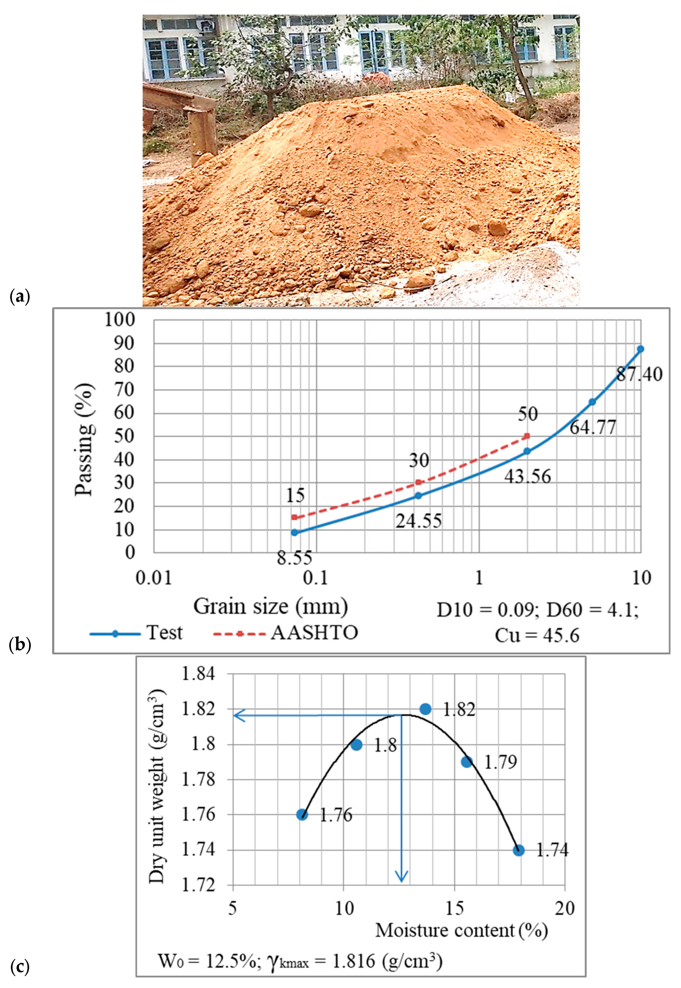
| Parameter | Unit | Value |
|---|---|---|
| Saturated density, γ | kN/m3 | 2.070 |
| Dry density, γk | kM/m3 | 1.816 |
| Friction angle, φsoil | degrees | 34.3 |
| Cohesion, csoil | Pa | 5100 |
| Plasticity Index IP | - | 8.55 |
| Uniformity coefficient Cu | - | 45.6 |
| pH | - | 5.9 |
| Ion Cl- | (mg/g) | 0.094 |
| Ion SO42- | (mg/g) | 0.497 |
| Parameter | Unit | Value |
|---|---|---|
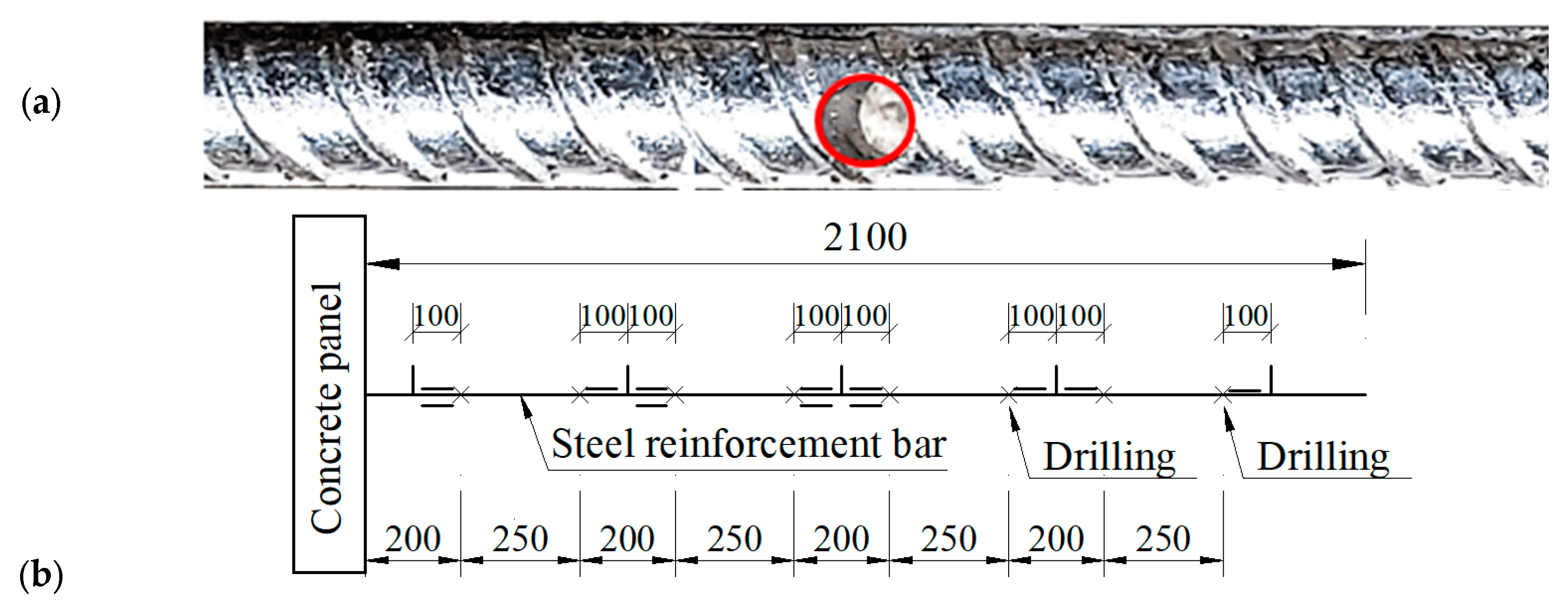
| Initial tensile strength of the steel reinforcement | N | 49,000 |
| Loss of tensile strength | N | 17,150 |
| Remaining tensile strength within the reinforcement | N | 31,850 |
| Drilling on the reinforcement bars to reduce their cross-sectional area | % | 26.6 |
| Drilling depth (Φ5) | mm | 8.1 |
| Parameter | Unit | Value |
|---|---|---|
| Concrete panel | ||
| Width | m | 0.75 |
| Height | m | 0.15 |
| Length | m | 1.5 |
| Young’s modulus | Pa | 2.1011 |
| Compressive strength of concrete | MPa | 35 |
| Foundation soil | ||
| Unit weight, γFound | kg/m3 | 2700 |
| Friction angle, φFound | degrees | 51 |
| Cohesion, cFound | Pa | 5.51.107 |
| Bulk modulus | Pa | 4.39.1010 |
| Shear modulus | Pa | 3.02.1010 |
| Backfill soil | ||
| Unit weight, γsoil | kg/m3 | 2070 |
| Friction angle, φsoil | degrees | 34.3 |
| Cohesion, csoil | Pa | 5100 |
| Bulk modulus | Pa | 1.5.107 |
| Shear modulus | Pa | 6.106 |
| Steel reinforcements | ||
| Length | m | 2.1 |
| Steel bar thickness | m | 0.010 |
| Calculation width | m | 1.5 |
| Number of longitutial bars per calculation width | strip | 4 |
| Young’ modulus | Pa | 2.1011 |
| Tensile strength | N/m | 31850 |
| Tensile failure strain | % | 0.19 |
| Shear stiffness | N/m2 | 2.107 |
| Parameter | Unit | Value |
|---|---|---|
| Backfill soil - Concrete panel | ||
| Normal stiffness | Pa/m | 2.4.106 |
| Shear stiffness | Pa/m | 2.4.106 |
| Friction angle | degrees | 26 |
| Backfill soil- Steel reinforcements | ||
| Shear stiffness | N/m2 | 2.107 |
| Cohension | N/m | 1.105 |
| Initial apparent friction coef: | ||
| Layer 4 | 1.917 | |
| Layer 3 | 1.751 | |
| Layer 2 | 1.586 | |
| Layer 1 | 1.420 |
| Depth (m) | Reinforcement layer | Full-scale model results | Current standards TCVN [14], AFNOR [12] |
||
|---|---|---|---|---|---|
| La (cm) | Le (cm) | La (cm) | Le (cm) | ||
| 0.375 | 4 | 95 | 115 | 90 | 120 |
| 1.125 | 3 | 95 | 115 | 90 | 120 |
| 1.875 | 2 | 60 | 150 | 67.5 | 142.5 |
| 2.625 | 1 | 60 | 150 | 22.5 | 187.5 |
Disclaimer/Publisher’s Note: The statements, opinions and data contained in all publications are solely those of the individual author(s) and contributor(s) and not of MDPI and/or the editor(s). MDPI and/or the editor(s) disclaim responsibility for any injury to people or property resulting from any ideas, methods, instructions or products referred to in the content. |
© 2023 by the authors. Licensee MDPI, Basel, Switzerland. This article is an open access article distributed under the terms and conditions of the Creative Commons Attribution (CC BY) license (http://creativecommons.org/licenses/by/4.0/).


