1. Introduction
Polymeric composite materials reinforced with carbon fibers are already used conventionally in aerospace and automotive industries and soon appear likely to become more and more involved in a broader range of engineering applications, requiring enhanced mechanical properties for reduced overall weight. Although considerable efforts have been made over the years to improve the design, analysis, and prevention of carbon fiber-reinforced composite laminates against damages due to low-velocity impact, their use in large-scale industrial applications remains quite limited. Indeed, the potential of these materials to sustain barely visible impact damage (BVID, i.e., substantial damages/failures that occur in the underlying layers with only a minor surface indent detectable by visual inspection on their external surfaces) is still a particular topic of concern for many researchers in the field of design for manufacturing the carbon fiber-reinforced polymeric laminates. At its core, the low-velocity impact (i.e., LVI) damage might affect a composite material's outer layers or the inner layers, and even both the outer and the inner layers [
1,
2,
3,
4,
5]. In this regard, it is worth mentioning that CFRP laminates exhibit a reduced absorption capacity of the projectile's kinetic energy, which inherently leads to a weak response at relatively low-velocity impact. In other words, while the metallic materials absorb the impact kinetic energy through elastic-plastic deformations, the reduced absorption capacity of carbon fiber-reinforced polymeric composite materials comes mainly due to their complex intra- and inter-ply damage mechanisms that extend laterally from the impacted area, such as delamination, matrix cracking and fiber-breakages [
6,
7,
8,
9,
10,
11]. However, the disadvantage in using such materials to build up load-carrying structures is not only given by the multitude, complexity, and combination of all these possible failure modes but also due to technical difficulties that generally occur when attempting to identify and quantify the precise shape and size of impacted damaged areas as well as their effects on the laminate's mechanical properties.
Over the years, considerable effort has been devoted to computational and experimental endeavors to develop a precise evaluation of CFRP laminates' post-impact compressive residual strength [
12,
13,
14,
15,
16,
17,
18,
19]. On the contrary, systematic research on CAI test procedures is considerably less numerous [
20,
21]. Even though some of the leading engineering corporations and standard organizations have published their own recommended practices for the CAI test (BSS 7260 [
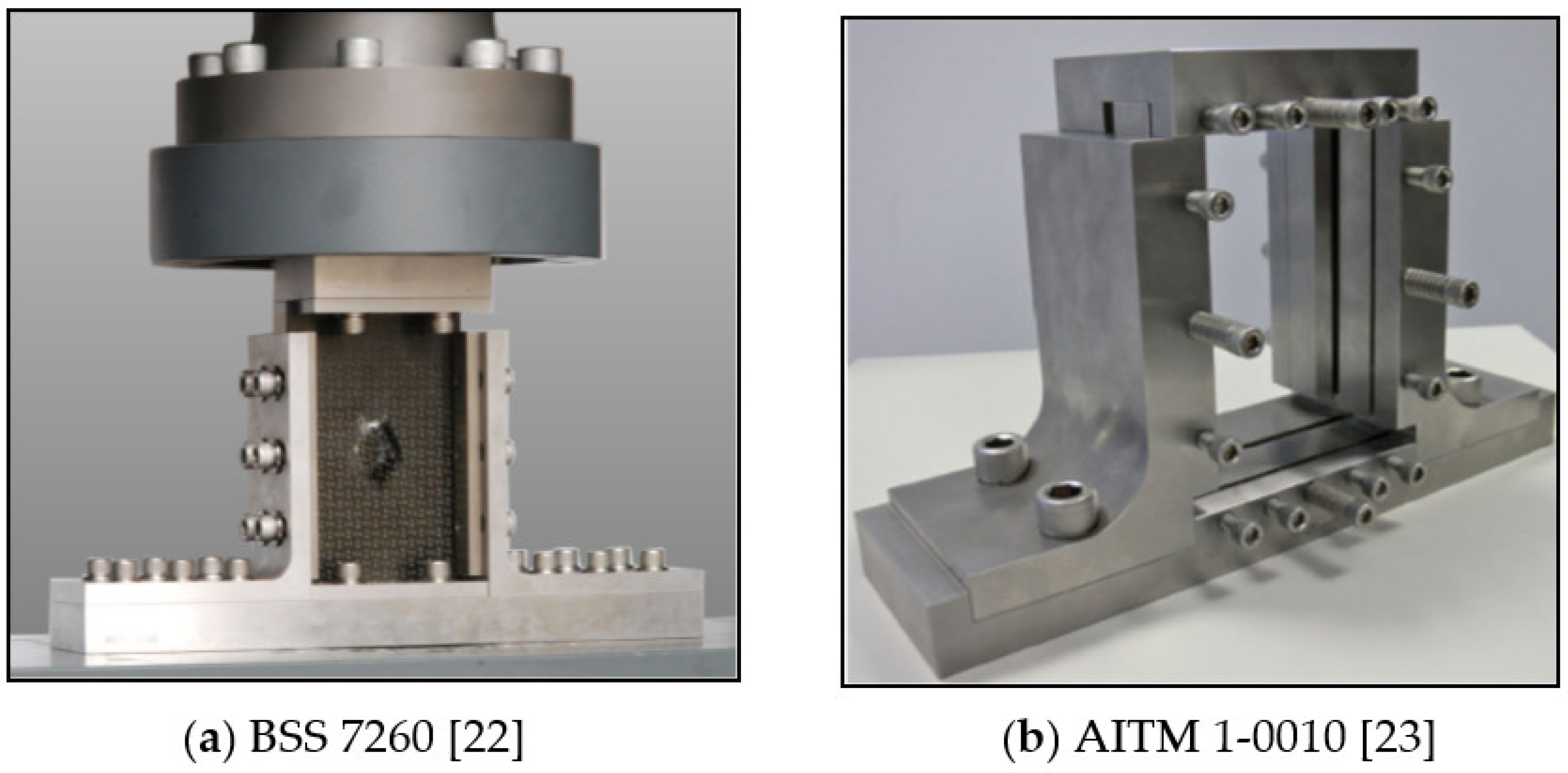
22], AITM 1-0010 [
23], NASA RP 1092 [
24], CRAG TR 88012 [
25], ASTM D7136 [
26], SACMA SRM 2R- 94 [
27], DIN 65561 [
28], ISO 18352 [
29], DIN EN 6038 [
30]), so far there are no compulsory requirements that rigorously specify either the size of specimens or other strictly-defined test parameters corresponding to certain particular conditions. Nevertheless, their recommendations are commonly used to generate the impact damages of composite laminates since they are essentially based on drop-weight tower devices [
31,
32,
33] that reproduce the low velocity falling weight impact on the external surfaces of rectangular plate specimens. As suggested by Sanchez-Saez [
34], the size of the specimen and the gripping mechanism may differ between investigations, but the impact devices and testing processes remain rather consistent.
2. Background
With the references mentioned above in mind, one may underline that the basic guidelines for the CAI test method and their related fixtures as figured out in Boeing Specification Support standard - BSS 7260 (see
Figure 1-a) are in some measure different to the ones outlined in Airbus Industries Test Method - AITM 1-0010 (see
Figure 1-b). In the BSS 7260 CAI test fixture, similar to ASTM D7136, SACMA SRM 2R-94, and DIN 65561, all sides of the specimen are guided but not gripped. On the other hand, a slightly modified fixture is described in ISO 18352 and DIN EN 6038 as per AITM 1-0010 specifications, in the sense that the specimen is clamped at the upper and bottom extremities, while the lateral sides are guided via a line contact.
NASA RP 1092, CRAG TR 88012, and even BSS 7260 standards typically use large specimens, so thick laminates are expected to be uniquely suited for such devices and procedures. However, all three of these testing specifications are widely conducted worldwide.
Only laminates, whose thicknesses lie between 2 mm and 5 mm, will be considered henceforward. Thus, some of these tests might be technologically expensive for such specimens as a significant volume of material processing is required and inadequate since the damage modes partly depend on the thickness of the laminate composite under analysis [
34,
35].
An overview of the literature in the field reveals that under CAI loading, complex damage mechanisms lead to ultimate failures by local buckling, delaminations, fiber breakage, or propagation of impact-induced matrix cracks. With that being said, whatever failure mechanism occurs in the compression failure process, care must be paid to make sure that specimens being tested fail due to compression rather than global buckling, local crushing, and/or compression shear at contact edges [
35,
36,
37]. In such a manner, the CAI test data may be considered valid and can be effectively used for damage tolerance design purposes.
Various loading fixtures have been proposed to prevent the laminate specimens from global buckling, compression shear, and/or crushing to the loading tabs. Some researchers overcame global buckling by using anti-buckling plates with a central hole to preserve the impact surface [
36,
37]. A downside of this method is that the impacted specimens with end tabs need clamping grips for fixation, the same as those used in tensile tests, which could imply additional processing to change their geometry before the compression test [
38]. However, using such tabs generally complicates the CAI test since an accurate alignment of the impacted specimen would also be needed. One way to avoid these drawbacks is to utilize slotted loading tabs that enable the specimen to be directly fixed between anti-buckling plates [
39]. Other approaches use adjustable fixture systems that can be fitted to the plate specimens' thicknesses; thus, neither lateral guides nor anti-buckling plates are necessary [
40]. Sanchez-Saez et al. [
34] developed a new test device to determine composite structures' CAI strength. Two anti-buckling plates (an upper and a lower) were placed to restrict the out-of-plane movement of the specimen. Both plates have U-shaped rectangular openings in the middle that left the specimen's central area free and did not modify the impact-damaged surfaces. The benefits of this CAI test configuration rely on its capability for testing thin composite laminate specimens prone to buckle during the post-impact compression test.
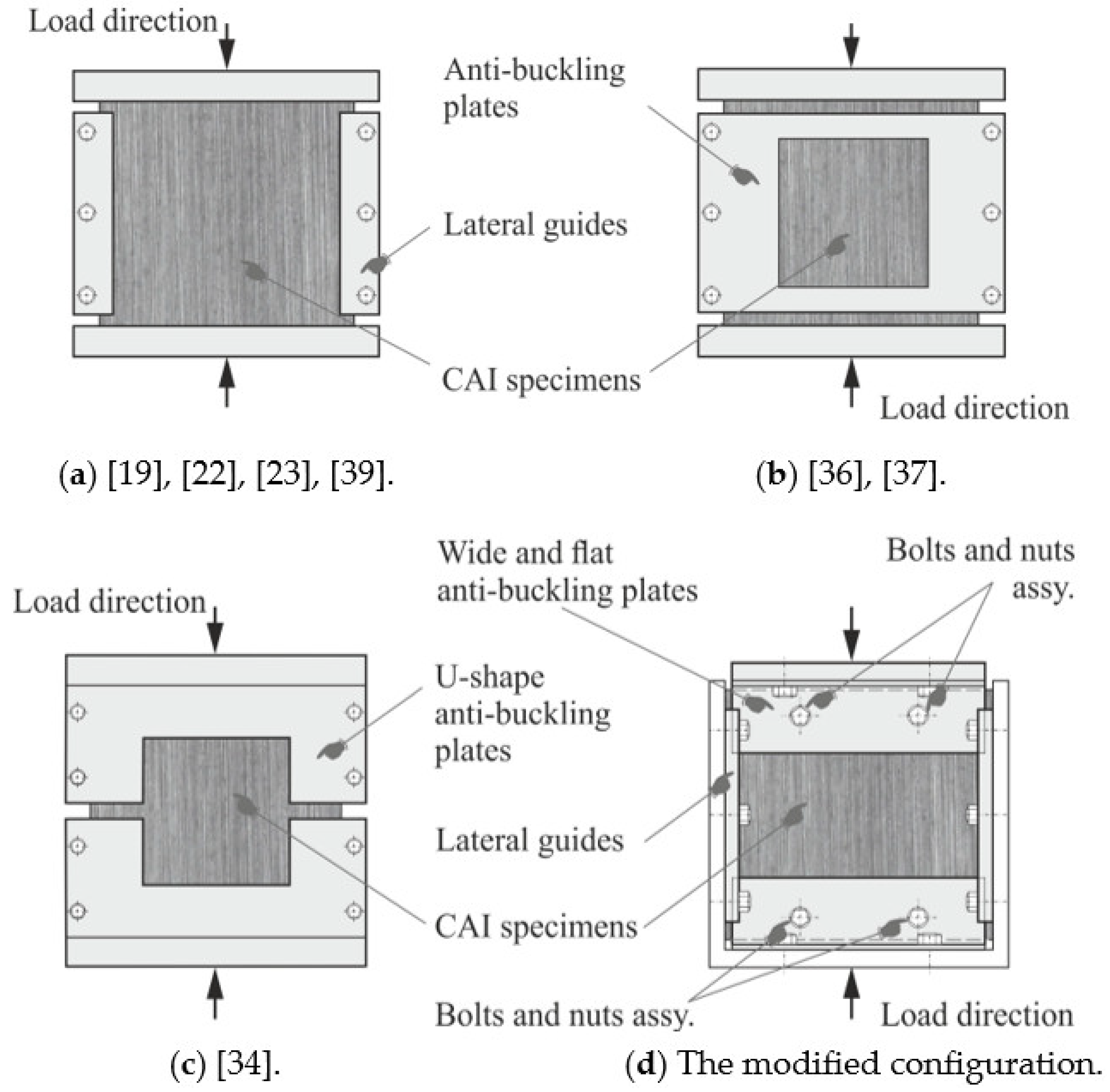
Figure 2-a to 2-c show the schematic representations of several common CAI test devices compared to the configuration proposed and outlined in this paper (see
Figure 2-d). One may observe that the proposed CAI test device is designed by keeping the lateral guiding sides as per BSS 7260 [
22], using two pairs of anti-buckling plates rather than the U-shaped ones proposed by Sanchez-Saez et al. [
34]. The specimen's upper and lower ends are fixed between two adjustable wide and flat anti-buckling plates through a removable bolt-nut assembly. For this reason, four circular holes must be drilled into the specimen after carrying out the impact tests. This technical solution relies on the fact that the specimen's active length is shortened, reducing the risk of global buckling. Besides, the bolts carry part of the load with minor localized bearing damage at the holes' contact edge, provided that the metallic plates act as washers by supporting the bolt-bearing region laterally [
41], thus avoiding the occurrence of crashing failures and at specimen loading edges.
With the aim of identifying the disparities between the static residual compressive strength for two particular CFRP symmetric laminate configurations of reversed angle-ply orientation, the data pertaining to LVI response, as well as the resulting compression load-displacement curves obtained by means of the proposed CAI test fixture (see
Figure 2-d), is analyzed and discussed in the next sections.
3. Materials and Methods
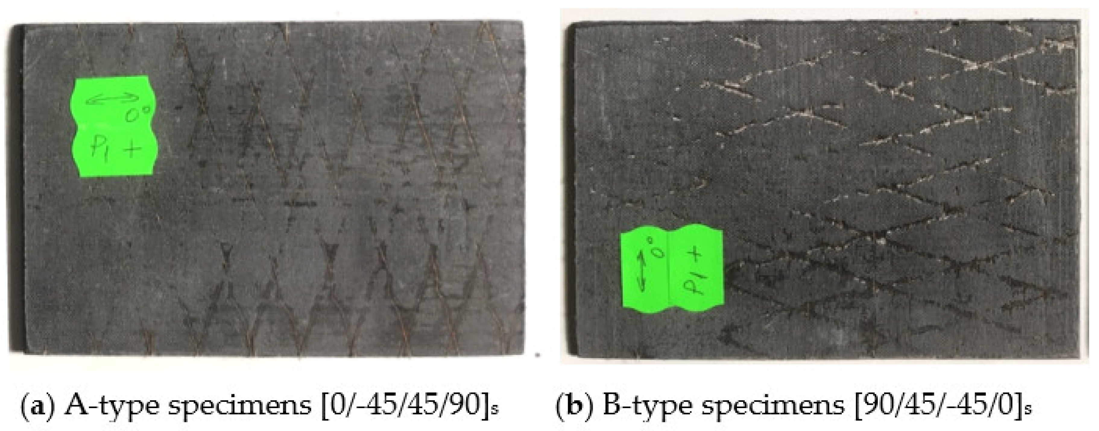
The rectangular plate specimens of 150 x 100 x 4.52 mm, made of epoxy vinyl ester matrix (Derakane 470-30) reinforced with carbon fibers, have been considered for this experimental investigation. In this regard, the laminate base plates used to cut out the specimens were manufactured manually at laboratory scale by brushing the resin on (with approx. 30% volumetric ratio) in two distinct symmetric lay-ups of reversed angle-ply orientation (i.e., [0/-45/45/90]
s versus [90/45/-45/0]
s), then exposed to high levels of vacuum, and finally, air-cured. As indicated in
Figure 3, the obtained specimens will be termed in what follows as A-type and B-type, respectively.
The experimental investigation was carried out within two subsequent steps. In the first, the laminate specimens were subjected to out-of-plane low-velocity impact intending to establish the level of barely visible impact damage BVID; then, in the second, with the aim to analyze the post-impact residual compressive behavior of symmetric angle-ply CFRP laminates with a reversed orientation that makes the object of this study, non-impacted reference specimens along with impacted specimens were tested to in-plane static compression.
3.1. Low-velocity impact tests
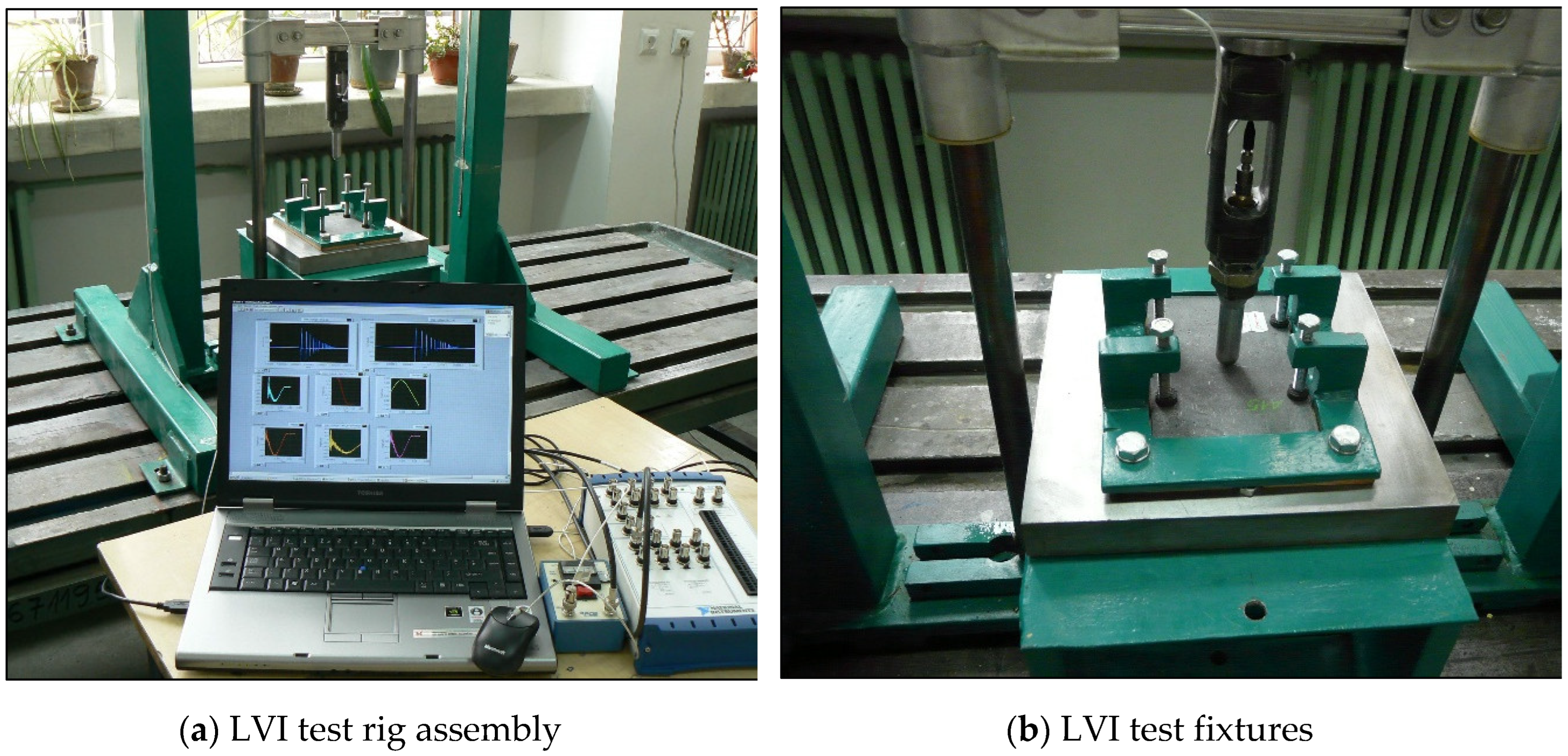
The CFRP laminate specimens were impacted using a laboratory-built instrumented falling weight test rig assembly, as presented in
Figure 4. Its functionality allows the adjustment of the impact velocity by changing the dropping height of a hemispherical projectile aligned vertically upon two guiding bars.
During the impact event, the specimen is clamped to a rigid steel supporting plate with a rectangular clearance of 100 x 75 mm2 through four tightening screws placed laterally, close to the specimen's lateral edges. Rubber-tip clamps were used to avoid local damage due to excessive tightening. At the beginning of each test, a hemispherical-nosed head projectile of 1.9 kg mass and 16 mm diameter is raised to the required drop height and left to fall onto the geometric center of the specimen's top face. The projectile's velocity during the impact event was monitored and recorded using the instrumented falling weight test devices, with the primary outputs being force and deflection versus time data, which were subsequently analyzed and converted into the impact energy values. Notably, the projectile was captured after the first impact event at each test run to prevent the multiple strikes upon the specimen.
The projectile velocities and impact energies corresponding to the level of BVID were first determined. In order to achieve this particular goal, the so-called “scale method” was used; namely, the weight of the projectile was kept constant while the falling height was increased gradually (corresponding to different initial velocities of 1 m/s, 3 m/s, 5 m/s, and 6 m/s). For each configuration, almost three tests up to BVID were carried out with the aim of obtaining the complete load-displacement curves. It was found that the impact velocity of 6 m/s corresponds to the BVID level for both configurations, as the average indentation depth measured after 24 hours reached 0,8 mm for A-type specimens, whereas a value of 0,7 mm was obtained for B-type specimens.
3.2. Static compression after impact tests
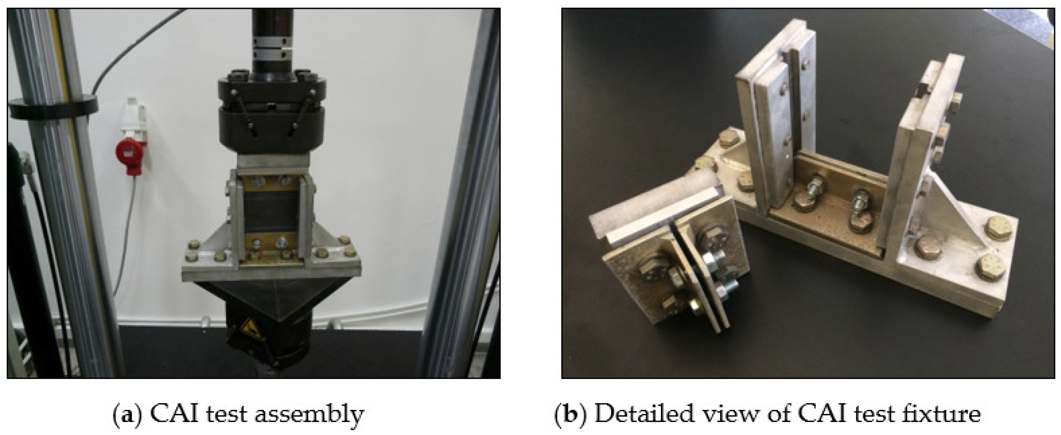
The static compression after impact CAI tests were conducted by a multipurpose servo-hydraulic universal testing machine, Walter-Bai, type LFV 50-HM. The setup of the compression after impact (CAI) assembly and fixtures is depicted in
Figure 5. After the impact event, four mounting holes were drilled into the specimen following a rectangular pattern with corners at 25 mm relative to the upper and lower edges and 30 mm from the lateral edges. A worn-off eight-faceted drill (Ø 12 mm, point angle 85 degrees) coated with a polycrystalline diamond was utilized without any cooling agent. Then, the specimen's upper and lower ends are fixed between two adjustable wide and flat anti-buckling plates by inserting the bolts through the mounting holes and tightening the nuts. As already highlighted in
Section 2, the bolts are supposed to carry part of the load with minor localized bearing damage at the holes' contact edge, provided that the metallic plates act as washers by supporting the bolt-bearing region laterally, thus avoiding the occurrence of compression shear and crashing failures and at specimen loading edges.
The embedded Walter-Bai acquisition system directly recorded the specimen's in-plane displacement against the compression load applied along the symmetrical axis direction of the specimen length. All the involved CAI static tests were conducted under displacement control with a 0.5 mm/min crosshead speed.
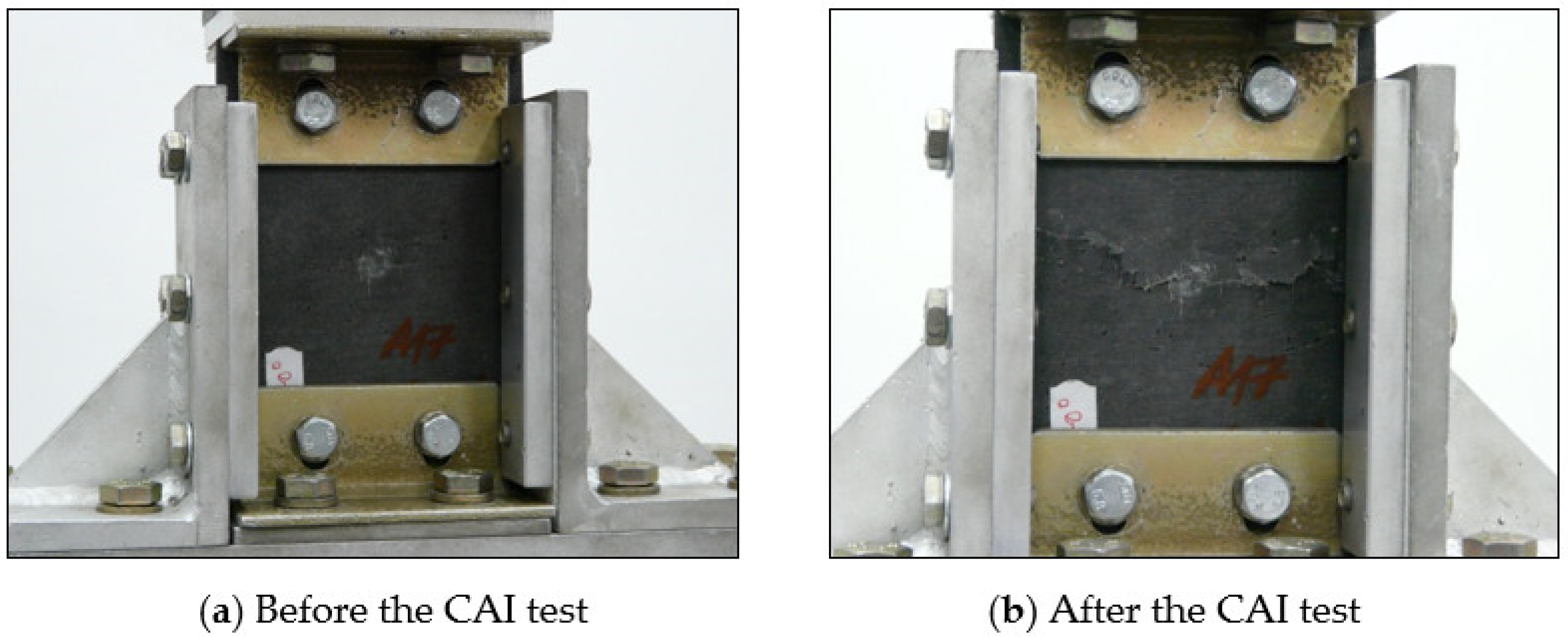
Figure 6-a shows an example of an A-type laminate plate specimen initially subjected to impact at 6 m/s, then clamped in the CAI fixture, intending to start the residual compressive static strength test. An example of a typical damage pattern obtained after the CAI test is shown in
Figure 6-b.
4. Results and discussion
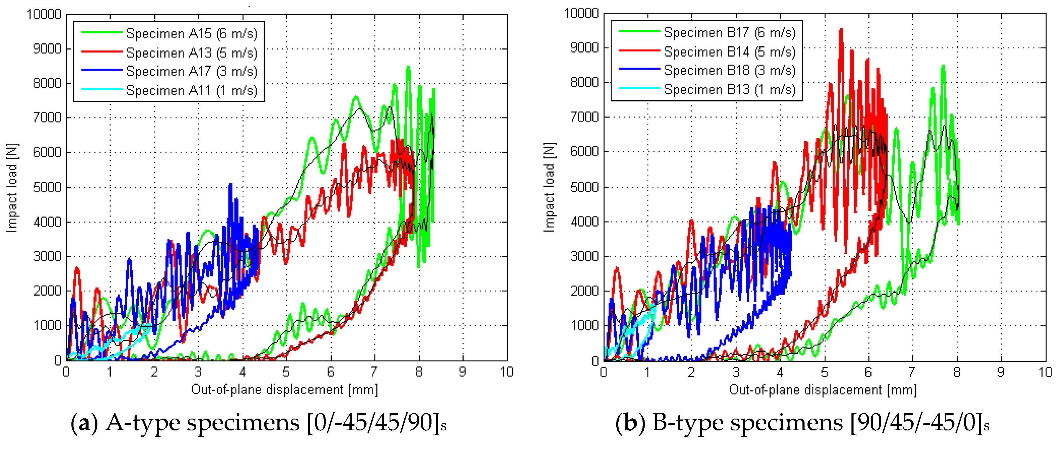
The load-displacement curves derived from LVI tests up to the BVID level are reported in
Figure 7 for both lay-up configurations. Due to significant overlapping, only one curve for each projectile’s velocity is portrayed in order to avoid data crowding. As expected [
42,
43], harmonic oscillations caused by the dynamic coupling between the projectile and specimen are apparent at the beginning of the impact event. For this reason, differences between the recorded curves are difficult to distinguish, and thus, a more accurate guess can be made by smoothing the curves. In this regard, for clarity purposes, in
Figure 7, the smoothed load-displacement curves corresponding to the projectile’s velocities of 5 m/s and 6 m/s are represented by thin black lines. As a result, one may note that in both configurations, the smoothed lines show a first closely linear part for all curves, which progressively attains a downward slope, followed by a second nearly linear segment. Along this second segment, the amplitude of oscillations becomes more obvious with the increase of the projectile’s velocity toward the BVID threshold (i.e., 6 m/s). The observed slope alteration is hypothesized to result from delamination initiation at an impact force of approximately 6 kN. In addition, the dynamic response appears to be amplified by the abrupt propagation of delaminations, as remarked by Schoeppner and Abrate. [
44].
Overall, no substantial disparities were observed in the general impact behavior between the two symmetrically reversed angle-ply lay-ups regarding the maximum load. However, a slight increase in stiffness can be observed for B-type specimens. Such a response may be attributable to the orientation of upper and lower laminate layers that align with the small side of the specimen (i.e., along the width) for B-type specimens, compared to the high side direction (i.e., along the length) in the case of A-type specimens. This supposition is also proven by the fact that the average indentation depth measured after 24 hours reached 0,7 mm for B-type specimens, whereas a value of 0,8 mm was obtained for A-type specimens. Conversely, regarding the amplitude of harmonic oscillations, the B-type specimens show somewhat higher values suspected to be caused by more significant internal damages (i.e., delaminations). Concerning the impact energy, almost the same mean values were obtained for both lay-up configurations at all considered levels of impact velocity below the BVID threshold: 0.94 J at 1 m/s, 8.5 J at 3 m/s, and 23.6 J at 5 m/s, respectively. Nevertheless, at the level of BVID (i.e., 6 m/s), a slight increase in impact energy was recorded for B-type specimens (i.e., 32.5 J) compared to A-type specimens (i.e., 31.7 J). As suggested by Kravchenko [
14], this is correlated with an increased damaged area within the laminate.
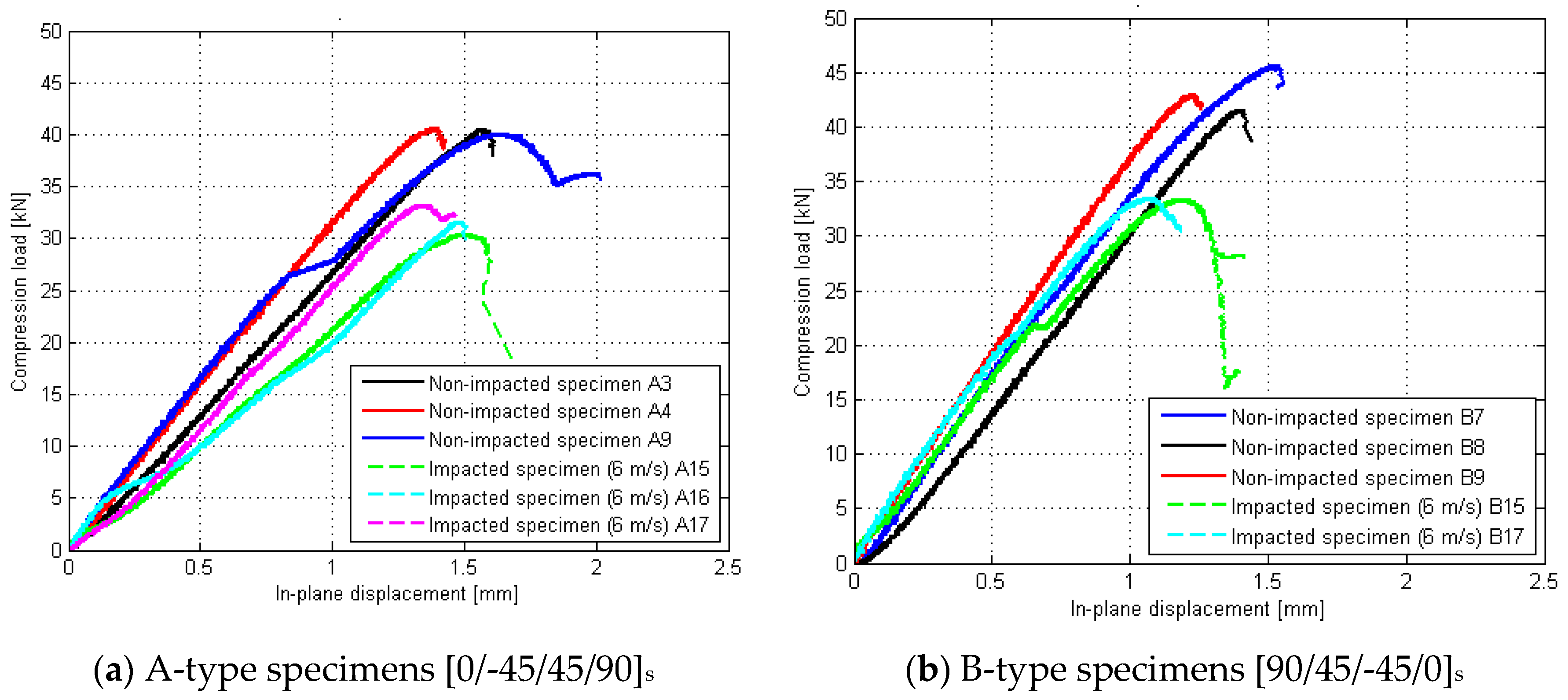
A few illustrative plots of the applied compression load in relation to specimen edge displacement, acquired during CAI tests, are shown in
Figure 8 for each angle-ply configuration considered. The compressive load-deflection curves of non-impacted specimens were also recorded to provide reference values. As expected [
14], although a significant scatter was observed, all specimens indicate similar trends with increasing the applied compressive load. It is worth mentioning that global buckling did not happen to all specimens (i.e., non-impacted and impacted) during the compression test; however, distortion of some curves can be observed, which is consistently related to the evidence of lateral deflection [
15]. On the other hand, in the case of minimal compressive loads [
45], the presence of minor flaws due to the specimen machining and the test fixture induces a progressive out-of-plane deflection of the laminate's central portion that generates delaminations until it splits into two or more sub-laminates. According to Tafreshi and Oswald [
46], as well as Amaro et al. [
47], the local buckling mode is significantly influenced by the sequence of laminate layering that governs the displacement response under the applied compression load.
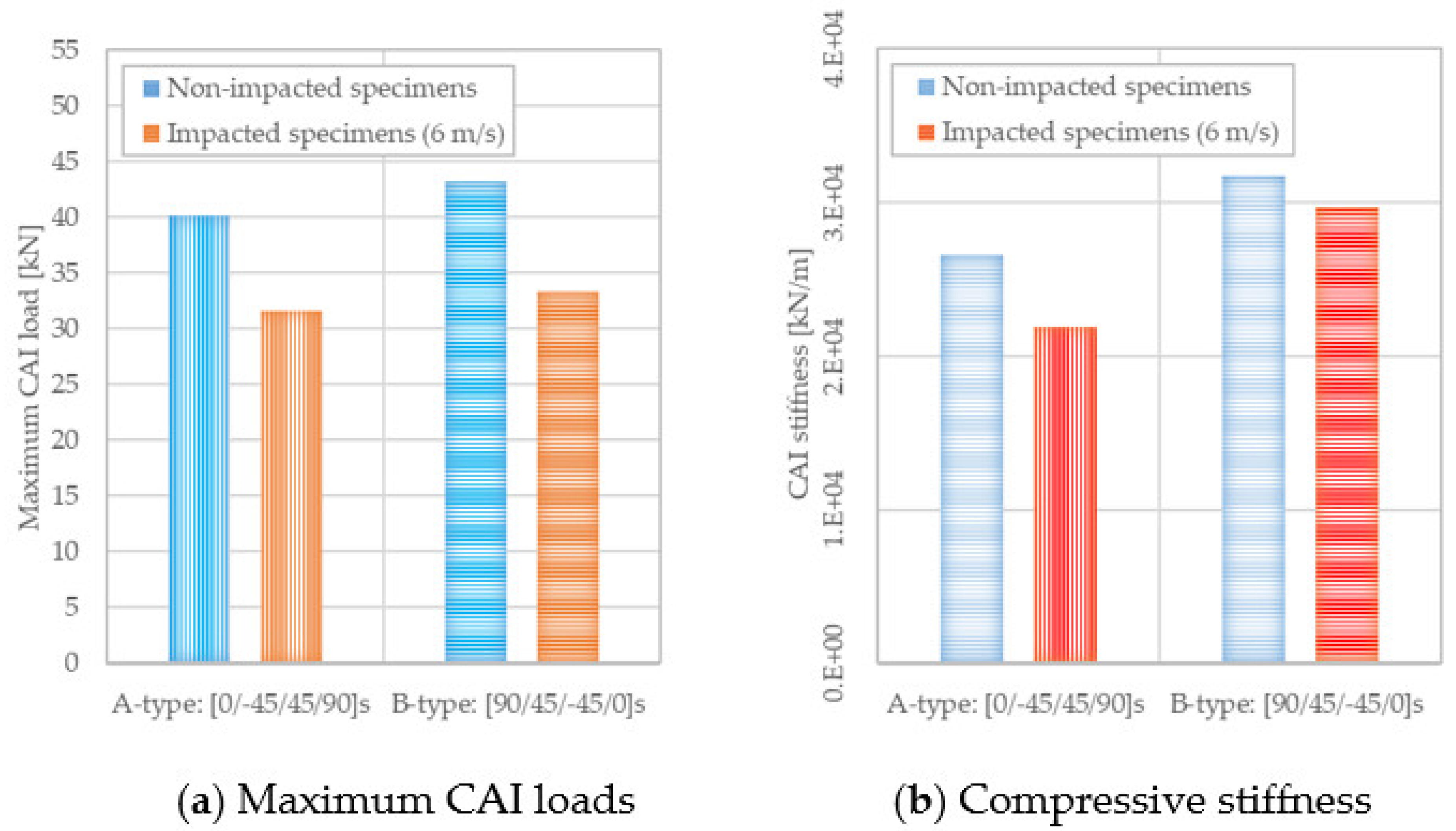
Figure 9-a shows a comparative histogram of maximum compression load between A-type and B-type lay-up configurations. Concerning the non-impacted specimens, one can observe an increase of 7% in maximum compression load for B-type specimens compared to those having A-type stacking layout.
Subsequently, relative to the reference values highlighted above, approximately the same percent decrease in the average values of maximum compression load (i.e., 22%) was recorded for both lay-up configurations impacted up to the BVID level (i.e., 6 m/s impact velocity). However, Sun and Hallett [
19] noted that the values of compressive strength acquired in the case of non-impacted reference specimens do not align with their failure under pure in-plane compression due to the plate instability exhibited prior to attaining those values.
On the other hand, as regards the compressive stiffness response, a reduction of 17 % was found for A-type specimens [0/-45/45/90]
s compared to 6 % for B-type specimens [90/45/-45/0]
s, (see
Figure 9-b). Such a greater reduction recorded for A-type specimens may be due to the transverse orientation of the middle plies, making the central sub-laminate less stiff, more unstable, and, thus, prone to failure under a lower compression load.
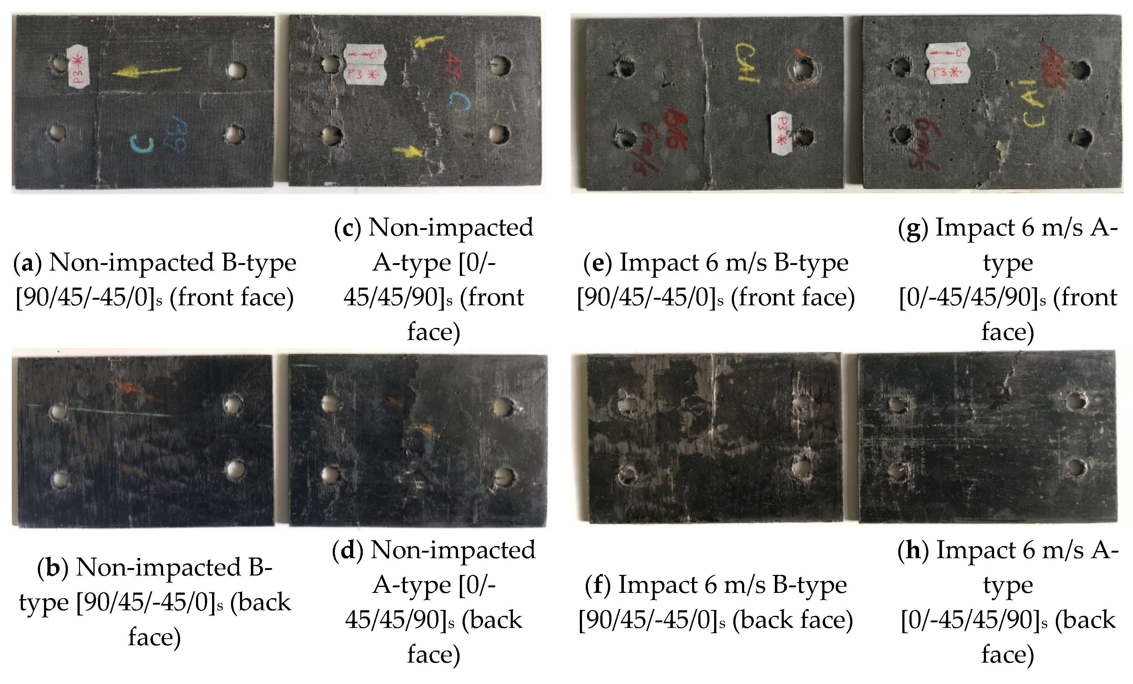
The typical compression damages are illustrated in
Figure 10-a, b, c, and d for a non-impacted (undamaged) specimen, while
Figure 8-e, f, g, and h show the damages of a specimen initially subjected to impact with a projectile velocity of 6 m/s. As mentioned previously, it was assumed that this velocity corresponds to the BVID level as the average indentation depth measured after 24 hours was 0,8 mm for A-type specimens, while a value of 0,7 mm was recorded for B-type specimens. One may observe that on the external layers (front and back faces of specimens), the damage is mainly caused by delamination extending perpendicular to the loading direction. However, all specimens typically exhibit compression-shear fracture modes across the thickness and some delamination that runs along the width. The fiber breakages also occur in both cases but are more pronounced in the case of A-type specimens [0/-45/45/90]
s, while local buckling of external layers is prone to occur for B-type specimens [90/45/-45/0]
s. In the case of impacted specimens, the damages were onset mainly from the central projectile indentation, which is not a rule for unimpacted specimens. After micro buckling and matrix plastic deformation, kink zones develop, which induce fiber buckling and the development of two planes of fracture. Localized damage is discernible in the bolted holes; however, this damage is not associated with the fracture line that traverses the specimens.
As the above figures show, characteristics shared by compression failures in A-type specimens [0/-45/45/90]s refer to substantial longitudinal delamination, accompanied by longitudinal fracturing and minimal fiber fracture in the external 0-degree layer that virtually forms the front face of the specimen. In contrast to the opposite face, which displayed a kink band and severe fiber fracture in the external layer, the delamination and fracturing were of a lesser extent. In B-type specimens [0/-45/45/90]s, while local buckling of external layers is prone to occur, much less delamination occurred on the convex face. The pre-existing delamination had expanded in the transverse direction (parallel to the external 90-degree fibers) when the final fracture occurred at the impact-damaged area. Hence, on the concave face, the kink bands split and protruded the 90-degree plies, fracturing the 0-degree fibers from below.
Following the BSS [
22] and AITM [
23] specifications, a modified CAI test fixture is proposed to investigate the response of CFRP laminate specimens predisposed to buckle and/or experience crushing failure at contact interfaces between specimen edges and the loading grips during post-impact compression testing. In such an approach, the specimen's upper and lower ends are fixed between two adjustable wide and flat anti-buckling plates through a removable bolt-nut assembly. For this reason, a rectangular pattern of four circular holes must be drilled into the specimen after carrying out the impact tests. This technical solution relies on the fact that the specimen's active length is shortened, reducing the risk of global buckling. Moreover, since greater deformation is required to develop a through-fastener load path in holes having a diameter tolerance of 2 mm, less stress concentration relief is expected around the bolted assembly. In this concern, as Sawicki and Minguet [
48], Kelly and Hallström [
49], and recently Ogasawara et al. [
50] highlighted, bolt hole clearance affects filled hole strength capability to a greater degree than any other geometric factor. According to the same references, through-thickness restraint of laminate deformation provided by the wide and flat anti-buckling plates significantly increases the filled hole bearing strength. For these reasons, the bolts carry part of the load with minor localized bearing damage at the holes' contact edges, provided that the metallic plates support the bolt-bearing region laterally, and therefore, the occurrence of crashing failures at specimen loading sides is avoided. Although it requires unfastening the nuts and removing the bolted assemblies after each test, compared to standard devices, the proposed CAI test device prevents the occurrence of global buckling and does not cause any edge-weakening effect. Therefore, for small batches of specimens, the modified CAI device is more suitable for determining the compression after the low-velocity impact response of both damaged and undamaged CFRP laminated specimens.
5. Conclusions
Two different layouts of CFRP laminate specimens with an average thickness of 4,2 mm and having reversed orientations of ply angles, namely A-type [0/-45/45/90]s and B-type [90/45/-45/0]s, respectively, were considered to study the influence of lay-up orientation on the compression response after low-velocity impact tests.
Concerning the non-impacted witness specimens, an increase of 7% in maximum compression load for B-type specimens compared to those with A-type stacking layout should be mentioned. Relative to these reference values, approximately the same percent decrease in the average values of maximum compression load (i.e., 22%) was recorded for both lay-up configurations impacted up to the BVID level (i.e., 6 m/s impact velocity). However, with regard to the compressive stiffness, a reduction of 17 % was found for A-type specimens [0/-45/45/90]s compared to 6 % for B-type specimens [90/45/-45/0]s. The greater reduction recorded for A-type specimens may be due to the transverse orientation of the middle plies relative to the load direction, making the central sub-laminate less stiff and, thus, prone to failure under a lower compression load. It can be concluded that the specimens with outer plies (face and back) having a different orientation relative to the direction of load application exhibit a lower reduction of compressive load capacity relative to the ones with outer layers oriented along the loading direction. In other words, the impact-carrying capacity of a composite structure can be effectively improved by arranging the orientation of outer layers at 45 degrees orientation to the loading direction.
A modified CAI test fixture is proposed to investigate the response of CFRP laminate specimens predisposed to buckle and/or experience crushing failure at contact interfaces between specimen edges and the loading grips during post-impact compression testing. It requires minimum processing by drilling the specimens before the CAI test; thus, the specimen's upper and lower ends are fixed between two adjustable wide and flat anti-buckling plates by tightening four bolt-nut assemblies while the lateral sides are simply supported so that not only the risk of global buckling is reduced, but also the occurrence of crashing failures at specimen-loaded edges is avoided.
