1. Introduction
Short-range wireless communication has expanded in recent years, which necessitates that academics create methods for short-range applications and establish guidelines for short-range communication. Thus, in 2002, the Ultra-wide Band (UWB) technology covering the frequency range of 3.1 GHz to 10.6 GHz was regulated by the Federal Communication Commission (FCC) for use in commercial applications. The UWB standards were created by IEEE and are 802.15.3a for high data rates and 802.15.4a for low data rates. For short-range wireless communication devices that need to transmit data at a rapid pace, this UWB band is perfect. The problem here is that short-range UWB applications are the only ones allowed due to FCC regulations requiring minimal power usage. For this reason, WPAN (Wireless Personal Area Network), WBAN (Wireless Body Area Network), RFIDs (Radio Frequency Identifications), sensor networks, and other applications are among the uses for UWB.
These applications are primarily utilized in interior environments where harmful ISI (Inter Symbol Interference) is caused by intensive multi-path propagation. Using multipath propagation, MIMO (Multiple Input Multiple Output) technology increases range and reliability without requiring the usage of additional frequency range while offering faster data throughput. MIMO systems improve the signal-to-noise ratio by increasing the variety (spatial, pattern, or polarization diversity), which strengthens the transmitted signal. As a result, the concept of using MIMO antennas with UWB range increases communication range and provides excellent connection reliability. The advantages of merging MIMO with UWB are enumerated in [
1] and [
2] and include enhanced connection quality, reduced interference, expanded coverage, increased data rate, and diversity.
Several antenna parts make up a UWB MIMO antenna. The size of handheld electronics is getting smaller due to the electronics revolution, which is also reducing available space. As a result, there is less space between the radiating antennas in UWB MIMO systems than there was previously, which results in a comparatively high mutual coupling between the antennas. Therefore, increasing the isolation between the antennas by avoiding mutual coupling is one of the primary problems in designing UWB MIMO antennas. There have been a lot of studies conducted recently to address this mutual coupling problem. Placing the antennas such that they are orthogonal to one another is the most widely used method [
3]. Other methods for mutual coupling include the use of neutralizing lines [
4], parasitic structures [
5], Defected Ground Structures (DGS) [
6], stub loading [
7], Frequency Selective Surfaces (FSS) [
8], metamaterial isolator [
9], meander line structures [
10], and Electromagnetic Band Gap (EBG) structures [
11].
In [
12], a four-element MIMO antenna is presented. The LTE spectrum is used by the four-element MIMO antenna, which has more than enough MIMO needs. At 148 × 68 mm2, the system that is being offered has a substantially wider area. Additionally, the lowest isolation level is only -10.5 dB. Additionally, low gain and efficiency are mentioned. A second MIMO system with two components is shown in [
13]. T-shaped stubs buried in the ground are used to decrease the mutual coupling. The antenna is 38.5 × 38.5 mm2 and has a minimum isolation of -15 dB. A two-element MIMO antenna is shown in [
14]. The design has a big area of 66 × 32 mm2 and only works in the lower UWB band. Using the ground plane's decoupling slot lowers the mutual coupling. In [
15], a quad-element MIMO-based antenna arrangement is suggested. By employing split ring resonators, the mutual coupling is minimized (SRR). This is an antenna intended for LTE, WiMAX, and Bluetooth applications. A proposed quad-element MIMO structure in [
16] uses the Electromagnetic Band Gap (EBG) in conjunction with the Defected Ground Structure (DGS) to accomplish isolation. Aside from this, -17.5 dB is the highest isolation offered. In [
17], an additional two-element UWB MIMO antenna is provided. A T-shaped stub is positioned in the ground plane to decrease the mutual coupling between the two parts. A T-shaped stub can reach a maximum isolation of -20 dB.
This research proposes a 52.8 × 29 mm2 compact MIMO UWB antenna with a thin structure that is suited for the general structure of UWB equipment. FR-4 is the substrate. A stub is positioned in between two MIMO antenna elements to reduce mutual interaction between antennas. After the prototype was constructed, its attributes were measured and contrasted with the outcomes of the simulation.
This paper is divided into three sections. Section II discusses the antenna design and its evolution, and section II describes the isolation of the proposed MIMO antennas. Section IV consists of the results including the return loss, VSWR, radiation patterns, and gain while section V will conclude this work.
2. Antenna Design
2.1. Single Element Design Evaluation
The patch and ground are located on the same side of the substrate, and the antenna shown in this study can be manufactured easily. The antenna is integrated within a 1.6 mm-thick Flame Retardant 4 (FR-4) dielectric sheet with a loss tangent of δ = 0.025, a constant dielectric of ε
r = 4.4, and other characteristics. First, the CPW-fed ground plane and the simple monopole are modified to optimize the single-element antenna.
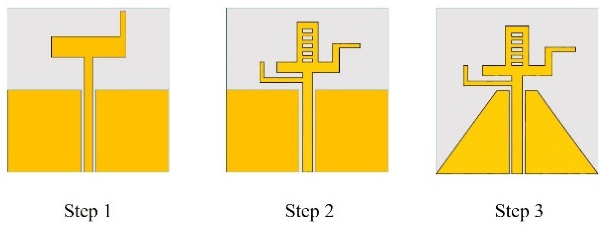
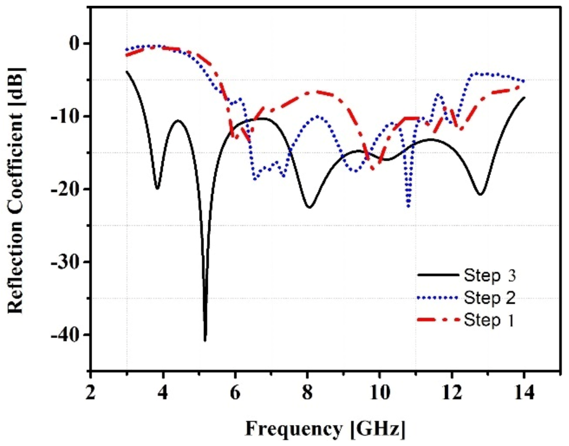
Figure 1 illustrates the assessment of a single-element UWB antenna. The design process starts from the simple monopole in step 1. In step 2, a ladder structure is then drawn, which causes the bandwidth to grow. Following that, a chamfer was added to the ground in step 3, allowing for the achievement of a UWB range that covered the frequency range of 3.3 GHz to 13.5 GHz. The suggested single-element antenna is 29 × 29 × 1.6 mm3 in total. With a thickness of 0.035 mm, copper makes up the radiating element.
Figure 2 displays the reflection coefficient of the single-element proposed antenna in three phases.
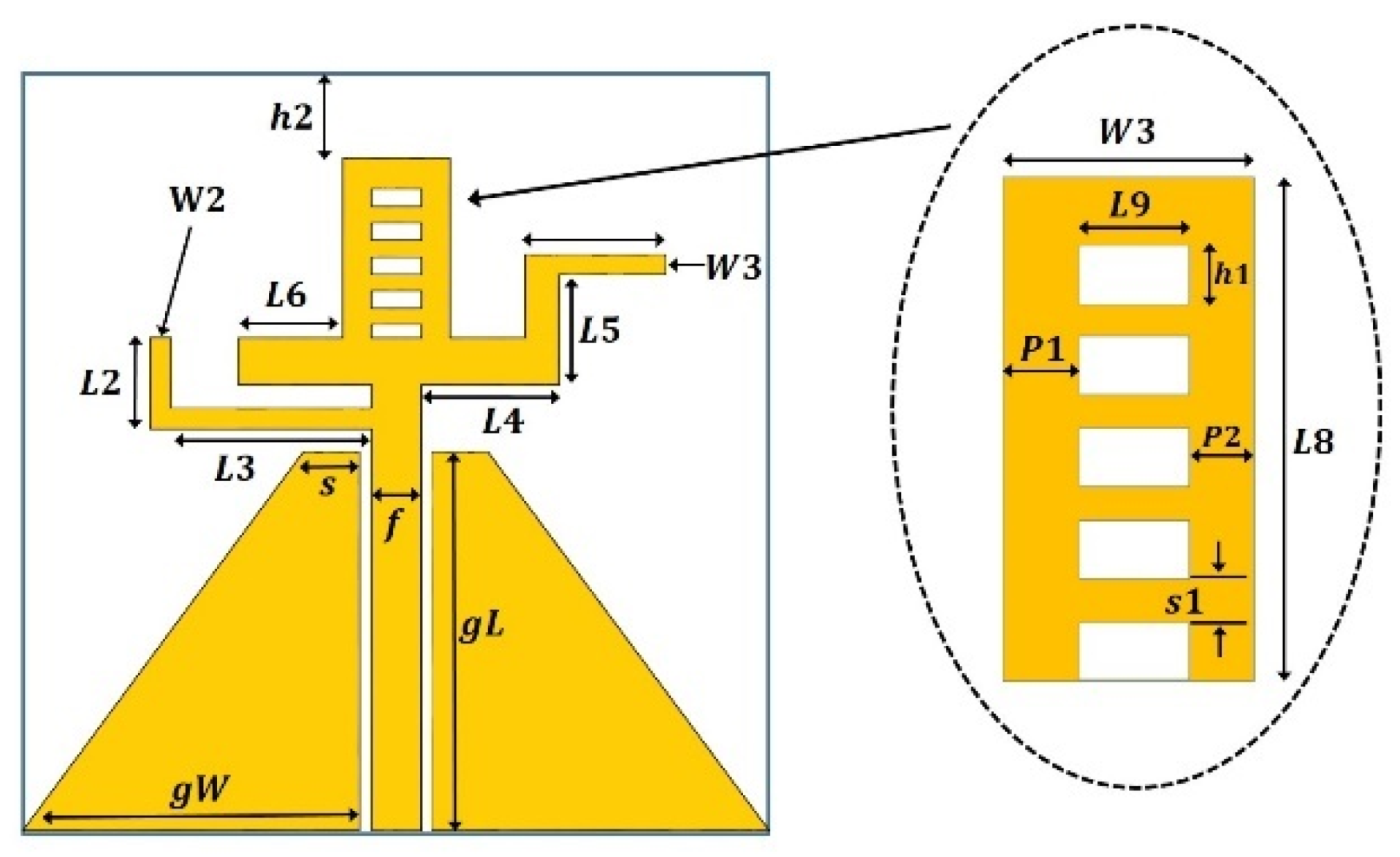
Figure 3 displays the labeled design of one proposed antenna, and
Table 1 below lists the antenna's actual measurements.
2.2. Antenna Configuration
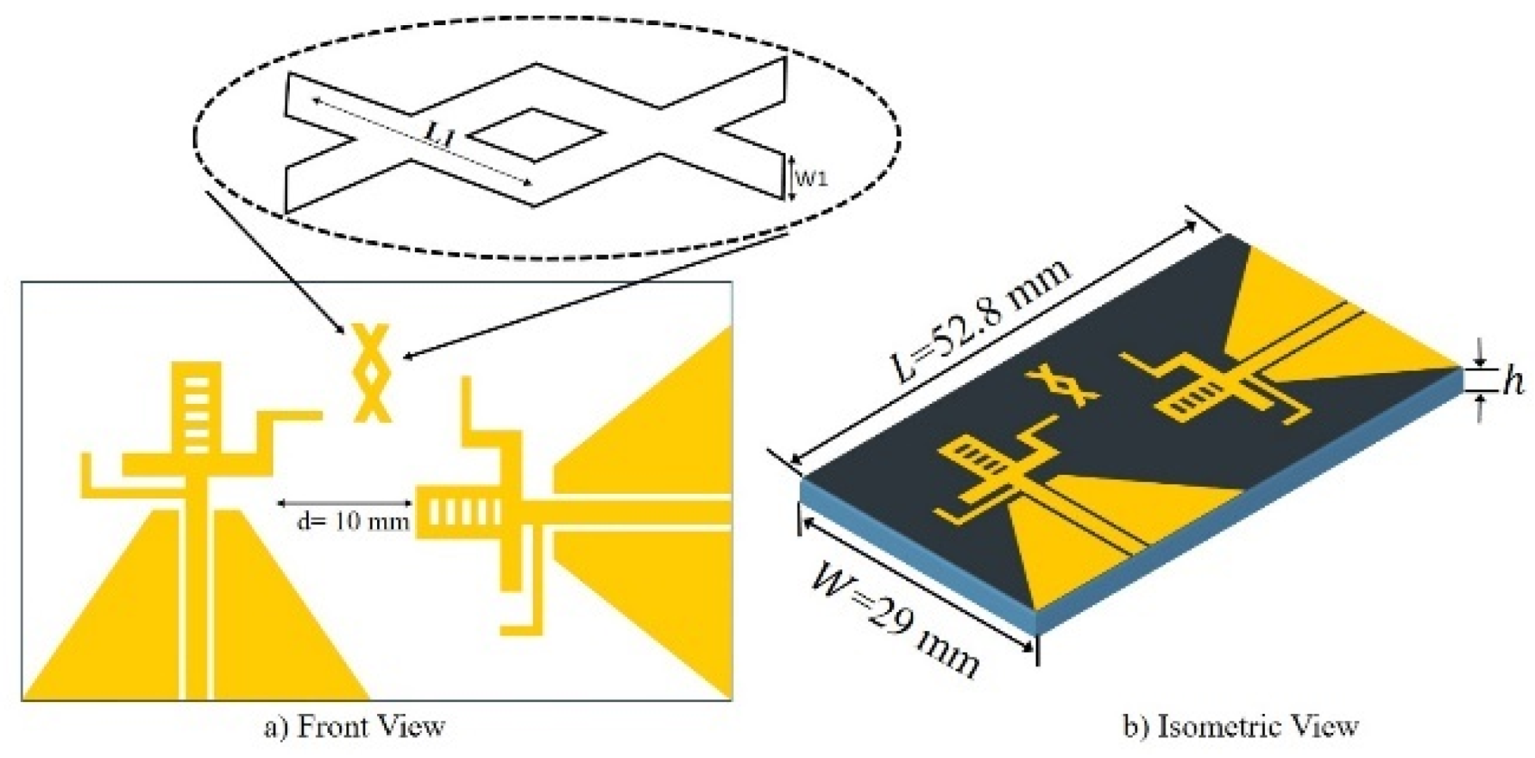
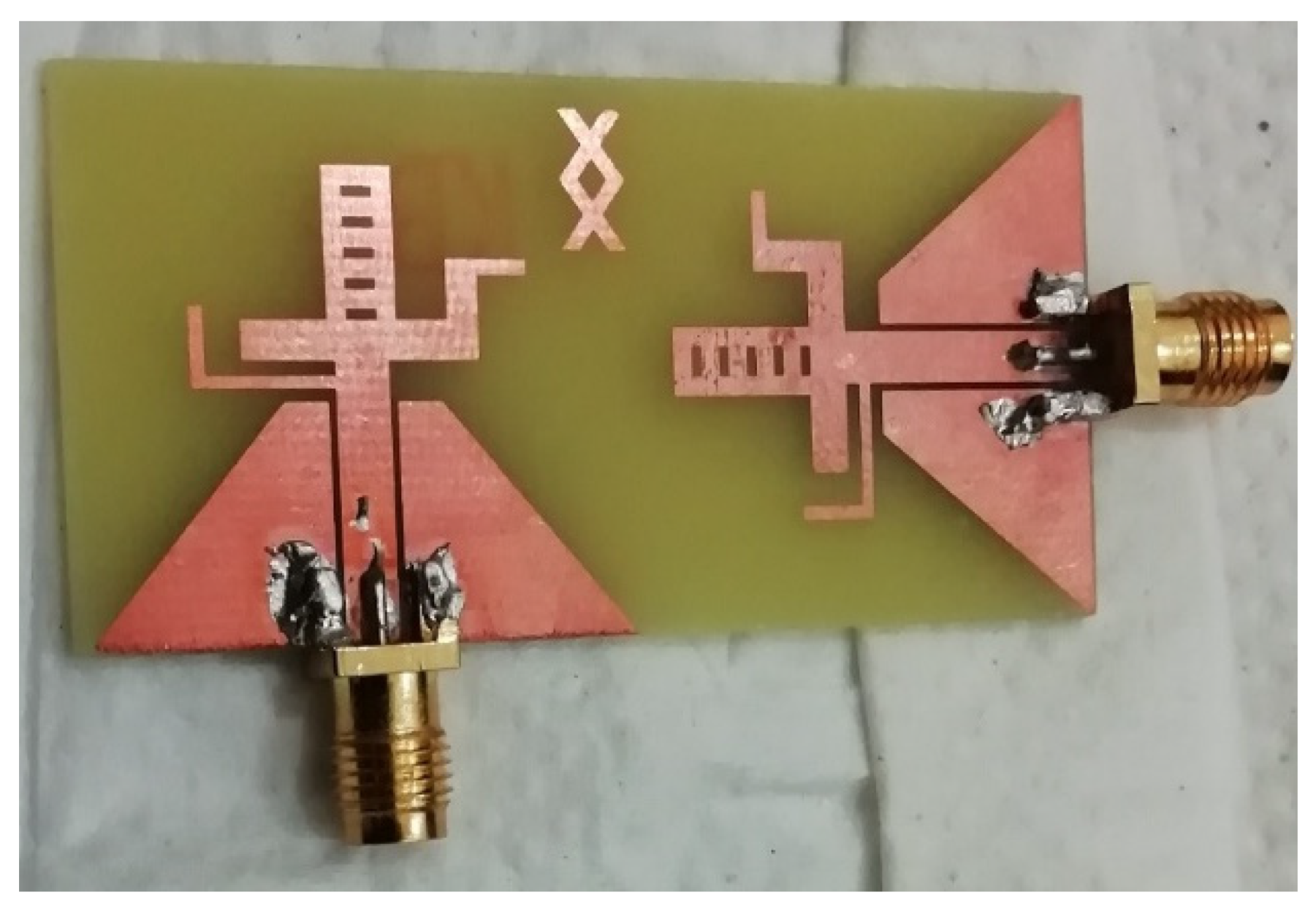
The CST Microwave Studio is used to simulate and optimize the two-element UWB MIMO antenna that is described. The suggested antenna's MIMO structure is made up of two antenna elements that are comparable to one another and are arranged orthogonally, as shown in [
3]. The given distance, d = 10 mm, is the separation between the antenna elements. To achieve the minimum criteria of mutual coupling of less than -15 dB, a parasitic element in the form of two combined crosses is also incorporated into the design. The suggested MIMO antenna's front and isometric views are depicted in
Figure 4 and
Figure 5, respectively, while the built prototype is shown in
Figure 5.
3. Isolation Mechanism
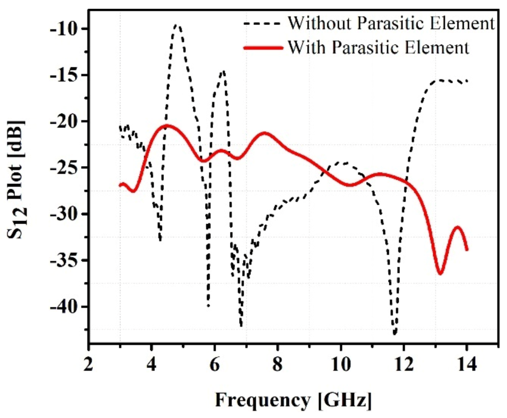
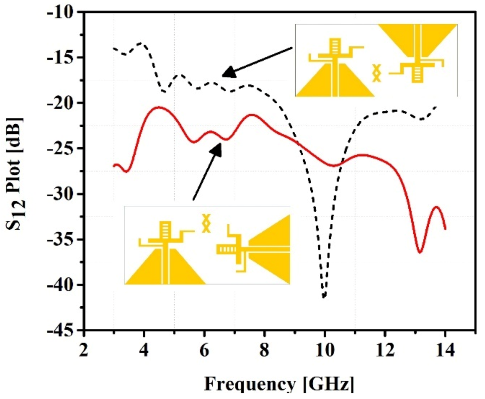
Two methods are used in this research to isolate the two antenna elements and reduce mutual coupling, which is necessary for the MIMO antenna to operate properly. A parasitic element is positioned in between the antenna elements, taking the shape of two crosses connected. The two antennas are positioned at a 90-degree angle to one another to further improve isolation. The impact of sandwiching the parasitic element between the antenna elements is depicted in
Figure 6. The two scenarios of antenna element orientation, considering the distance between them, are depicted in
Figure 7.
4. Results and Discussion
4.1 Return Loss
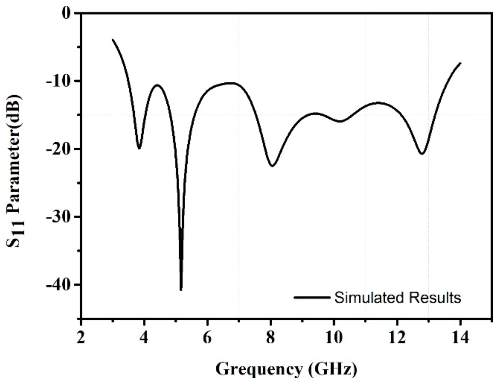
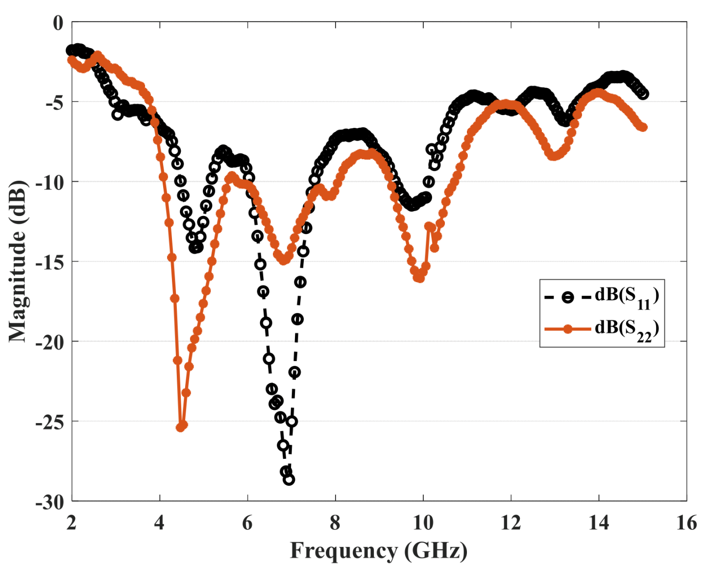
The frequency range for the suggested antenna is 3.3 GHz–13.5 GHz.
Figure 8 displays the antenna's S-parameter plot within the previously mentioned frequency range, while
Figure 9 displays the prototype's measured results. These findings demonstrate a convincing relationship between simulated and experimental data, although there is an approximately 15% mismatch due to connector losses and some other metallic lab equipment.
4.2 VSWR
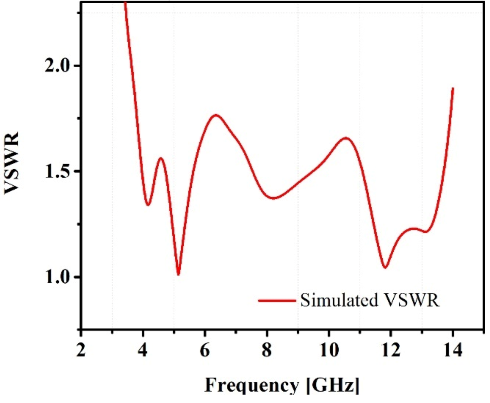
Figure 10 displays the voltage standing wave ratio (VSWR) simulation result for the suggested antenna. At some frequencies in a desired UWB band, the obtained VSWR values are 1.33, 1.04, and 1.42 for 3.8 GHz, 5.2 GHz, and 8.0 GHz respectively, all these values are less than 2, indicating that an antenna has valuable impedance matching.
4.3 Current Distribution
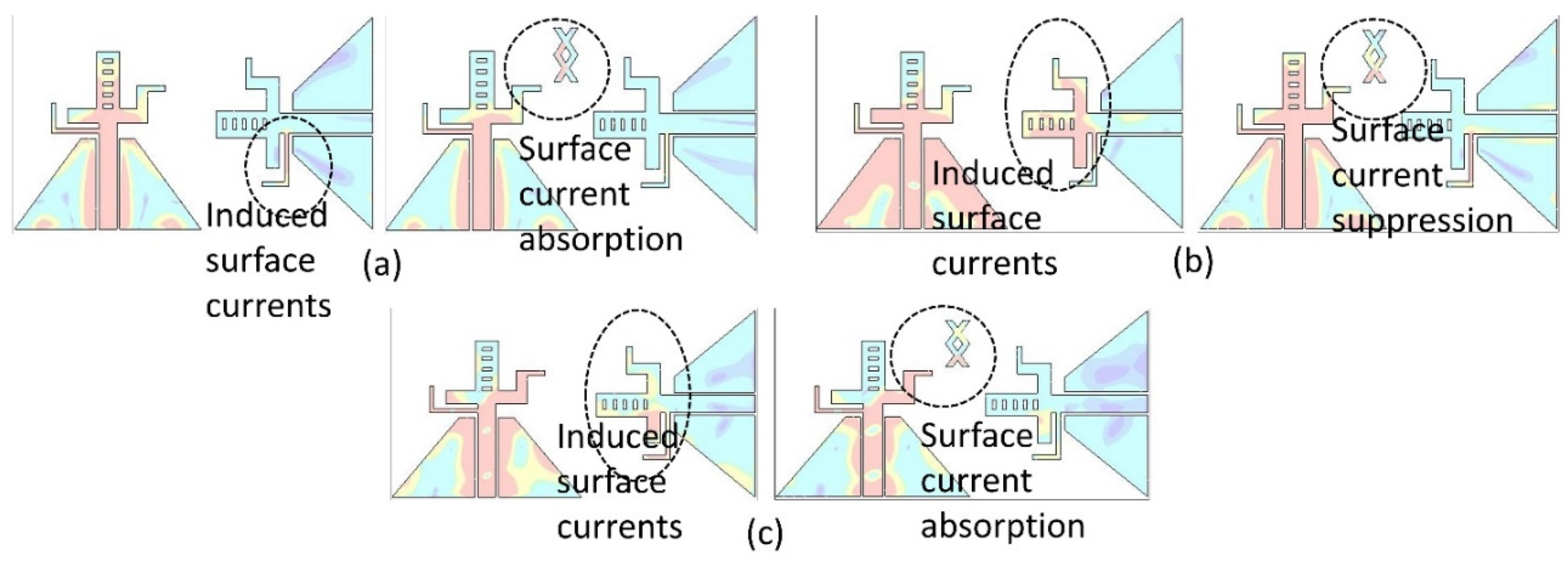
Figure 11 displays the current distribution at the antenna's resonance frequencies. A frequency band of 3.8 GHz is produced, as
Figure 11a illustrates, where the current distribution is maximum across the feed line and in the center of the radiator.
Figure 11b makes it clear that the frequency of 5.2 GHz is reached at feed line and upper part of patch, respectively when current intensity reaches its maximum. For the resonance frequency of 8.0 GHz, the lower cross of parasitic element is absorbing the induced current that was affecting the adjacent antenna element in
Figure 11c.
4.4 Radiation Pattern and Measurement Setup
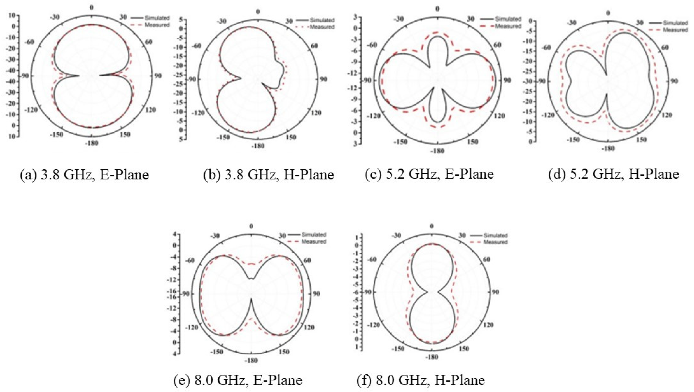
The normalized simulated and measured radiation patterns of the E-plane and H-plane at the frequencies of 3.8, 5.2, and 8.0 GHz are shown in
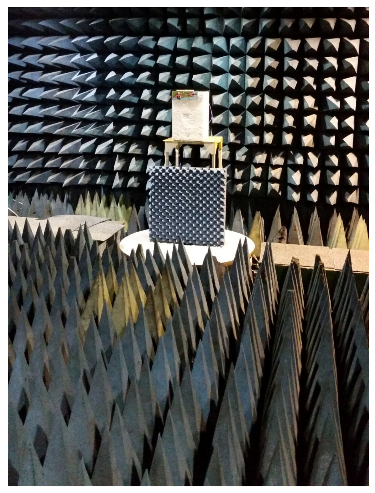
Figure 12. The measurement setup of a proposed MIMO antenna is shown in
Figure 13. Moreover, the radiation patterns are showing similarity to some extent which shows that there is an effective radiation behavior in the described band. These far-field radiation plots show that the antenna has an omnidirectional pattern which meets it suitable for future IoT applications.
4.5 MIMO Performance Parameters
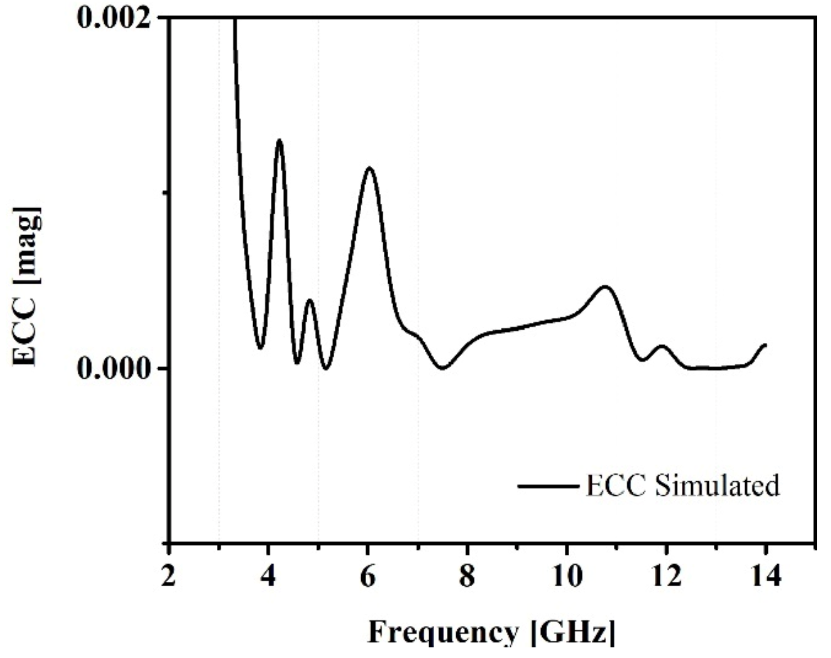
Instead of employing far-field parameters, scattering parameters can be used to find the values of the Envelope Correlation Coefficient (ECC), which provides a more precise measurement of ECC without requiring the measurement of the 3D radiation pattern. The following equation represents the relationship, which assumes a rich scattering environment. Moreover, visually displayed in
Figure 14.
We can calculate the diversity gain with the help of ECC which is depicted in
Figure 15. The relationship between the diversity gain and ECC is given as:
The correlation coefficient and diversity gain are shown to be positively correlated; a lower correlation coefficient corresponds to a higher diversity gain. Therefore, greater isolation between the antenna elements is needed to prevent low diversity gain.
4.6 Gain and Efficiency
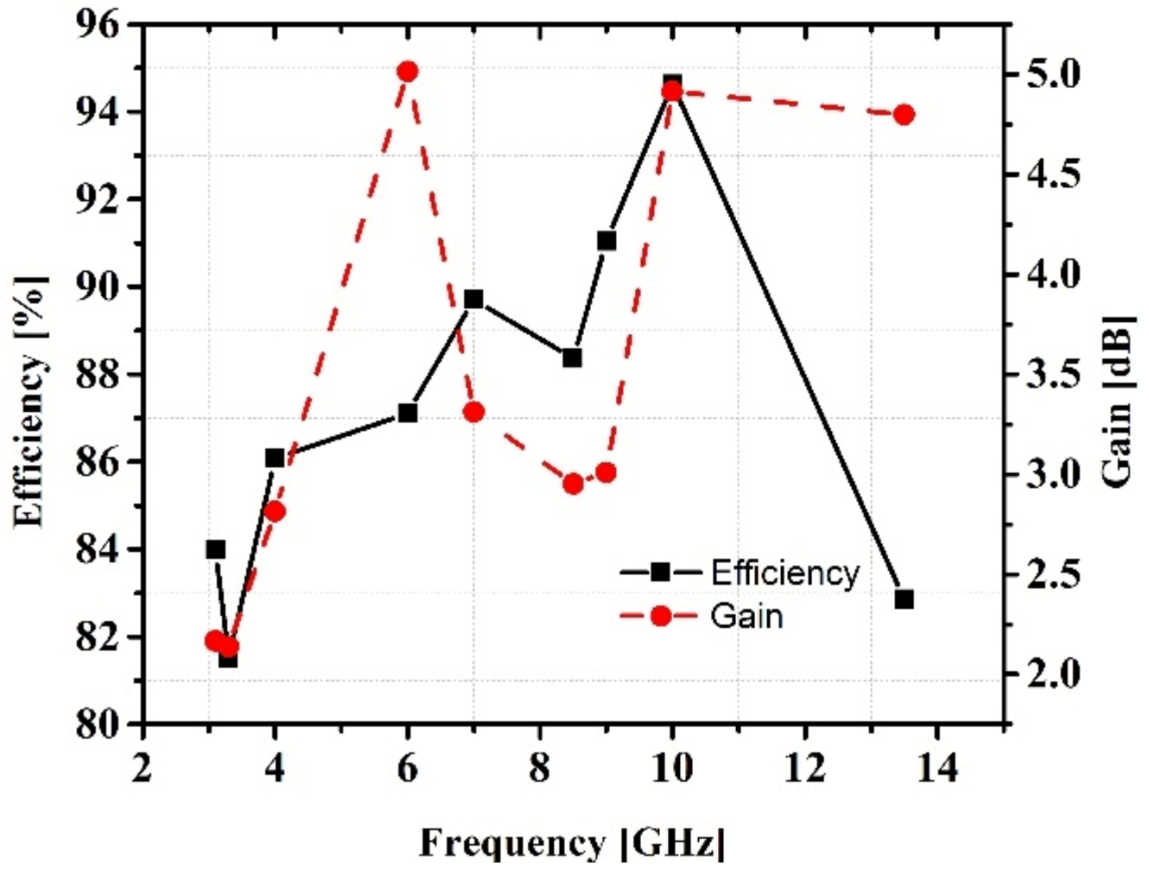
The CST Microwave Studio's far-field monitor is used to compute the gain and efficiency at various frequencies. The transmitted power in the direction of an isotropic source is described by an antenna's gain. If the transmitting antenna has a gain of 3dB, the power it receives will be twice as much as the power it receives from the lossless isotropic antenna, assuming that the input power is the same in both scenarios. The antenna's gain in this study changes over the frequency range from 2.1 to 4.9 dB. Certain wire-free communication standards are satisfied by the gain of the suggested antenna.
82% is the lowest efficiency value that has been observed. The various bands of operation and significant loss in the FR-4 substrate have an impact on the efficiency and diminish the radiation efficiency. Nonetheless, the radiation efficiency falls between 81% and 94%, indicating that the power received in the far-field region exceeds 50% of the input power, allowing the antenna to function well in the applications mentioned.
Figure 16 displays radiation efficiency and antenna gain. In
Table 2, provided work is contrasted with the recently published work.
5. Conclusions
As next-generation networks present obstacles, there is a growing desire to do more with less. An antenna's wideband capability optimizes the amount of space at the user site by better controlling the number of antennas. A proposed UWB CPW-fed microstrip patch antenna is intended for use in future Internet of Things (IoT) applications. Over the complete range of interest, the proposed antenna achieves more than 86% radiation efficiency. Both experimentation and modeling are used to evaluate the antenna's performance. When it comes to the performance parameters gain, efficiency, ECC, radiation pattern, and wide bandwidth, the design performs well. The CST Microwave Studio was used to assess proposed antenna. To verify simulation return-loss results, antenna prototype model is tested, and measured. The agreement between the simulated and measured findings is satisfactory.
Author Contributions
Conceptualization, Z.M. and A.E.; methodology, M.Z.; software, Z.M.; validation, N.B.; formal analysis, S.S.; investigation, M.Z.; resources, N.B.; writing—original draft, Z.M.; writing—review and editing, M.Z.; visualization, S.S.; Project administration, Y.A.; supervision, Y.A. All authors have read and agreed to the published version of the manuscript.
Data Availability Statement
Data can be shared upon request.
Conflicts of Interest
The authors declare no conflict of interest.
References
- M. A. Ul Haq, and S. Koziel, “Ground Plane Alterations for Design of High-Isolation Compact Wideband MIMO Antenna,” in IEEE Access, vol. 6, pp. 48978-48983, 2018.
- Malviya, L., Panigrahi, R., & Kartikeyan, M. (2017). MIMO antennas with diversity and mutual coupling reduction techniques: A review. International Journal of Microwave and Wireless Technologies.
- L. Liu, S. W. Cheung, and T. I. Yuk, “Compact MIMO Antenna for Portable Devices in UWB Applications,” in IEEE Transactions on Antennas and Propagation, vol. 61, no. 8, pp. 4257-4264, Aug. 2013. [CrossRef]
- S. Zhang and G. F. Pedersen, “Mutual Coupling Reduction for UWB MIMO Antennas with a Wideband Neutralization Line,” in IEEE Antennas and Wireless Propagation Letters, vol. 15, pp. 166-169, 2016. [CrossRef]
- K. Ding, C. Gao, D. Qu, and Q. Yin, “Compact Broadband MIMO Antenna with Parasitic Strip,” in IEEE Antennas and Wireless Propagation Letters, vol. 16, pp. 2349-2353, 2017. [CrossRef]
- M. A. Ul Haq and S. Koziel, “Ground Plane Alterations for Design of High-Isolation Compact Wideband MIMO Antenna,” in IEEE Access, vol. 6, pp. 48978-48983, 2018. [CrossRef]
- Yu Yin, Jingsong Hong, Chaoming Luo, Muhammad AMIN, A Compact Planar UWB MIMO Antenna using modified ground stub structure, IEICE Electronics Express, Article ID 14.20170883.
- Hassan, T., Khan, M.U., & Sharawi, M.S. (2018). FSS based Radiation Pattern Decorrelator for MIMO Antenna. 2018 IEEE International Symposium on Antennas and Propagation & USNC/URSI National Radio Science Meeting, 355-356.
- Z. Qamar, L. Riaz, M. Chongcheawchamnan, S. A. Khan and M. F. Shafique, “Slot combined complementary split ring resonators for mutual coupling suppression in microstrip phased arrays,” in IET Microwaves, Antennas & Propagation, vol. 8, no. 15, pp. 1261-1267, 9 12 2014.
- J. Ghosh, S. Ghosal, D. Mitra, and S. R. Bhadra Chaudhuri, “Mutual Coupling Reduction Between Closely Placed Microstrip Patch Antenna Using Meander Line Resonator,” Progress In Electromagnetics Research Letters, Vol. 59, 115-122, 2016.
- Jiang, T., Jiao, T., & Li, Y. (2018). A Low Mutual Coupling MIMO Antenna Using Periodic Multi-Layered Electromagnetic Band Gap Structures.
- J. Choi, W. Hwang, C. You, B. Jung, and W. Hong, “Four-Element Reconfigurable Coupled Loop MIMO Antenna Featuring LTE Full-Band Operation for Metallic-Rimmed Smartphone,” in IEEE Transactions on Antennas and Propagation, vol. 67, no. 1, pp. 99-107, Jan. 2019.
- L. Kang, H. Li, X. Wang, and X. Shi, “Compact Offset Microstrip-Fed MIMO Antenna for Band-Notched UWB Applications,” in IEEE Antennas and Wireless Propagation Letters, vol. 14, pp. 1754-1757, 2015. [CrossRef]
- H. Hu, F. Chen, and Q. Chu, “A Wideband U-Shaped Slot Antenna and Its Application in MIMO Terminals,” in IEEE Antennas and Wireless Propagation Letters, vol. 15, pp. 508-511, 2016. [CrossRef]
- R. Anitha, P. V. Vinesh, K. C. Prakash, P. Mohanan, and K. Vasudevan, “A Compact Quad Element Slotted Ground Wideband Antenna for MIMO Applications,” in IEEE Transactions on Antennas and Propagation, vol. 64, no. 10, pp. 4550-4553, Oct. 2016.
- Wenjing Wu, Bo Yuan, and Aiting Wu, “A Quad-Element UWB-MIMO Antenna with Band-Notch and Reduced Mutual Coupling Based on EBG Structures,” International Journal of Antennas and Propagation, vol. 2018, Article ID 8490740, 10 pages, 2018.
- D. Yadav, M. P. Abegaonkar, S. K. Koul, V. N. Tiwari, and D. Bhatnagar, “Two Element Band-Notched UWB MIMO Antenna with High and Uniform Isolation,” Progress In Electromagnetics Research M, Vol. 63, 119-129, 2018.
- Mathur, R. & Dwari, S. (2018). Compact 4-Port MIMO/Diversity Antenna with Low Correlation for UWB Application. Frequenz, 72(9-10), pp. 429-435. Retrieved 19 Jul. 2019.
- Wenjing Wu, Bo Yuan, and Aiting Wu, “A Quad-Element UWBMIMO Antenna with Band-Notch and Reduced Mutual Coupling Based on EBG Structures,” International Journal of Antennas and Propagation, vol. 2018, Article ID 8490740, 10 pages, 2018. [CrossRef]
- Anitha, R., Vinesh, P.V., Prakash, K.C., Mohanan, P., & Vasudevan, K. (2016). A Compact Quad Element Slotted Ground Wideband Antenna for MIMO Applications. IEEE Transactions on Antennas and Propagation, 64, 4550-4553.
- A. A. Ibrahim, J. Machac, R. M. Shubair and M. Svanda, “Compact UWB MIMO antenna with asymmetric coplanar strip feeding configuration,” 2017 IEEE 28th Annual International Symposium on Personal, Indoor, and Mobile Radio Communications (PIMRC), Montreal, QC, 2017, pp. 1-4. [CrossRef]
- H. Hu, F. Chen, and Q. Chu, “A Wideband U-Shaped Slot Antenna and Its Application in MIMO Terminals,” in IEEE Antennas and Wireless Propagation Letters, vol. 15, pp. 508-511, 2016. [CrossRef]
- L. Kang, H. Li, X. Wang, and X. Shi, “Compact Offset Microstrip-Fed MIMO Antenna for Band-Notched UWB Applications,” in IEEE Antennas and Wireless Propagation Letters, vol. 14, pp. 1754-1757, 2015. [CrossRef]
- J. Choi, W. Hwang, C. You, B. Jung, and W. Hong, “Four-Element Reconfigurable Coupled Loop MIMO Antenna Featuring LTE Full-Band Operation for Metallic-Rimmed Smartphone,” in IEEE Transactions on Antennas and Propagation, vol. 67, no. 1, pp. 99-107, Jan. 2019. [CrossRef]
- R. Hussain, M. S. Sharawi and A. Shamim, “An Integrated Four-Element Slot-Based MIMO and a UWB Sensing Antenna System for CR Platforms,” in IEEE Transactions on Antennas and Propagation, vol.66, no. 2, pp. 978-983, Feb. 2018. [CrossRef]
- S. W. Zehra, M. Zahid, and Y. Amin, “A Compact 2 Element MIMO Antenna for UWB Applications,” 2021 IEEE Asia Pacific Conference on Wireless and Mobile (APWiMob), 2021, pp. 247-252, Author 1, A.; Author 2, B. Book Title, 3rd ed.; Publisher: Publisher Location, Country, 2008; pp. 154–196. [CrossRef]
- Tatheer Ayesha, Aqsa Siddique, Muhammad Zahid, Asma Ejaz, Yasar Amin, and Hannu Tenhunen. 2022. “A Broadband MIMO Antenna for UWB Applications”. Technical Journal 27 (02), 30-36. https://tj.uettaxila.edu.pk/index.php/technical-journal/article/view/1655.
- S. Muzaffar, D. Turab, M. Zahid, and Y. Amin, “Dual-Band UWB Monopole Antenna for IoT Applications,” Engineering Proceedings. 2023; 46(1):29. [CrossRef]
|
Disclaimer/Publisher’s Note: The statements, opinions and data contained in all publications are solely those of the individual author(s) and contributor(s) and not of MDPI and/or the editor(s). MDPI and/or the editor(s) disclaim responsibility for any injury to people or property resulting from any ideas, methods, instructions or products referred to in the content. |
© 2024 by the authors. Licensee MDPI, Basel, Switzerland. This article is an open access article distributed under the terms and conditions of the Creative Commons Attribution (CC BY) license (http://creativecommons.org/licenses/by/4.0/).
