1. Introduction
Road mobility is a crucial element of economic progress and has become an indispensable aspect of contemporary civilization. Nevertheless, approximately two-thirds of the thermal energy generated by internal combustion engines in automobiles is squandered through the emission of exhaust gases or dissipated through cooling solutions. In response to the difficulties posed by limited fossil fuel resources and environmental pollution, engineers are actively engaged in creating novel electric cars and exploring methods to enhance the effectiveness of combustion engines. Thermoelectric generator (TEG) modules can directly transform high-temperature exhaust gases into electrical energy. Converting waste heat from engines into electrical energy using TEG modules and storing it in battery systems to power the advanced electrical systems of cars would enhance fuel efficiency and lower the temperature of waste heat, thus reducing environmental pollution. The topic of heat exchangers in waste heat recovery systems has been extensively examined [
1,
2,
3]. Due to the elevated temperature of exhaust gases from internal combustion engines, most research efforts have been directed at exhaust systems [
4,
5,
6,
7,
8,
9,
10]. C. Ramesh Kumar and his colleagues [
11] used the finite element software FLUENT@ to model and contrast heat exchangers in TEG modules with hexagonal, triangular, and rectangular geometries. It was discovered that the temperature distribution of the heat exchanger shell is more evenly spread when exhaust gases pass through a rectangular heat exchanger. This makes the rectangular heat exchanger better suited for use in automotive thermoelectric generator (ATEG). In their research, S. Ezzitouni and colleagues [
9] examined the impact of altering the temperature and flow of exhaust gases from diesel engines on the power generation of ATEG. These performance metrics encompass key engine variables, such as torque and engine speed. The investigation revealed that the waste heat generated by torque exerts a more significant influence on thermoelectric chips' power output than engine speed. Additionally, it was discovered that as the engine load rises, the TEG module produces sufficient power to counterbalance the rise in pump loss power. Furthermore, applying suitable thermal insulation to the TEG module can significantly enhance its power production.
Extensive research has been conducted on single-stage and dual-stage thermoelectric cooler-thermoelectric generator (TEC-TEG) systems in the context of studying the cold end of the ATEG [
12,
13,
14]. In their study, Liu et al. [
15] have shown a dual-stage TEG module that achieves a peak power output of around 250 W when operated at a hot-side temperature of 473 K. Rui et al. [
16] have focused their research on improving the waste heat recovery of TEG modules in military sport utility vehicles (SUVs). They have proposed four ways to better this process. Due to its increased heat-carrying capacity relative to air, water is more efficient at reducing the temperature at the cold end of the ATEG when used as a cooling medium [
17].
The ATEG module consists of four main components: the TEG, heat exchanger, cooling system, and clamping element. The TEG and the heat exchanger have crucial functions in determining energy conversion efficiency. The design of the flow channel within the heat exchanger cavity considerably impacts the efficiency of waste gas heat exchange and the resulting pressure drop, affecting the quantity of heat that can be used for generating electricity. This study aims to examine and contrast various heat exchanger designs to determine how they affect the power that the TEG produces at various waste gas flow rates and temperatures. Furthermore, it explores how the features of TEG materials impact energy conversion effectiveness.
2. Mathematical Model
2.1. Thermoelectric Theory
The TEG chip comprises multiple thermocouples connected in series. The relationship between the Seebeck coefficient, thermal conductivity, and internal resistance of a single thermocouple is expressed as follows:
where
αp and
αn are the Seebeck coefficients of the P-type and N-type thermoelectric materials, respectively, and
αpn represents the Seebeck coefficient of a thermocouple pair.
λp and
λn are the thermal conductivities of the P-type and N-type thermoelectric materials, respectively, and K represents the thermal conductivity through the thermocouple.
ρp and
ρn are the resistivities of the P-type and N-type thermoelectric materials, respectively, and
Rpn represents the internal resistance of the thermocouple.
Ap and
An are the cross-sectional areas of the P-type and N-type thermoelectric materials, respectively, and
Lp and
Ln are the lengths of the P-type and N-type thermoelectric materials, respectively. From these parameters, the open-circuit voltage
Voc, internal resistance
RTE, current
I, output power
P, heat absorbed at the hot end
Qh, the heat released at the cold end
Qc, and the thermoelectric chip's thermal efficiency
ηTE can be calculated using the following relationships:
In the Equations (4-10) mentioned above, NTE represents the number of thermocouple pairs in the TEG chips. Th and Tc represent the hot and cold temperatures at the thermocouple's hot and cold junctions. Rload denotes the external load resistance.
2.2. The Law of Energy Conservation
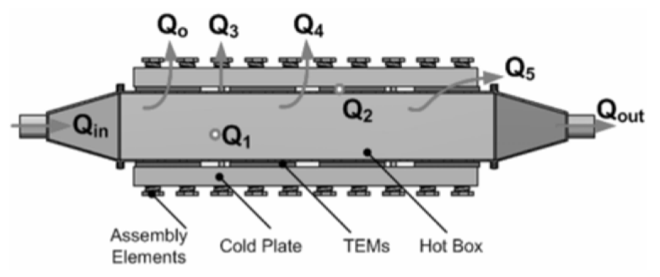
The thermal energy of the engine exhaust, as it passes through the heat exchanger, is equal to the sum of the heat gains by the TEG and the heat losses. This relationship is represented as follows [
18]
where
Qin and
Qout are the thermal energies at the inlet and outlet of the heat exchanger, respectively.
Q0 represents the actual heat gained by the TEG.
Q1 is the heat lost through convection and radiation from the surface of the heat exchanger without the TEG.
Q2 is the heat lost through convection and radiation from the gaps within the TEG chip.
Q3 is the heat lost through thermal conduction from the clamping element of the TEG module.
Q4 is the heat lost through the gaps between multiple TEG chips.
Q5 represents the heat consumed due to contact thermal resistance.
The overall efficiency η of the TEG module is defined as the ratio of the output power W of the TEG module to the heat supplied by the engine exhaust
Qexh. This relationship is expressed as follows:
where
W represents the output power of the TEG module, and
Qexh is the heat energy supplied by the engine exhaust. This heat energy is the same as the thermal energy lost by the engine exhaust in the heat exchanger, which is represented as
Qin -
Qout in Equation (11).
Figure 1.
Heat flow direction in thermoelectric devices [
18].
Figure 1.
Heat flow direction in thermoelectric devices [
18].
2.3. Fins’ Function
Fins' primary function is to increase waste exhaust heat extraction and enhance heat conduction efficiency. Heat conduction is directly proportional to the heat transfer area, heat transfer coefficient, and temperature difference. One can focus on increasing the heat transfer area, improving the heat transfer coefficient, or raising the temperature difference to enhance heat conduction. Since the operating temperature is usually fixed or limited, standard methods include enhancing the heat transfer coefficient or increasing the heat transfer area. Increasing the heat transfer coefficient can be achieved through forced convection or two-phase flow while using fins, which is a method to enlarge the heat transfer area. The relationship for heat conduction is expressed as follows:
where
is the rate of heat conduction, ℎ is the irradiance, representing the amount of heat transferred per unit area per unit temperature difference,
A is the cross-sectional area through which heat is being conducted, and
ΔT is the temperature difference driving the heat transfer.
3. Numerical Methods
3.1. Model Establishment
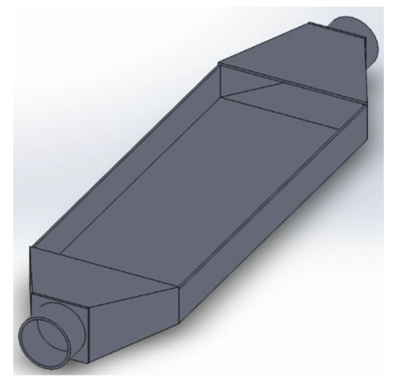
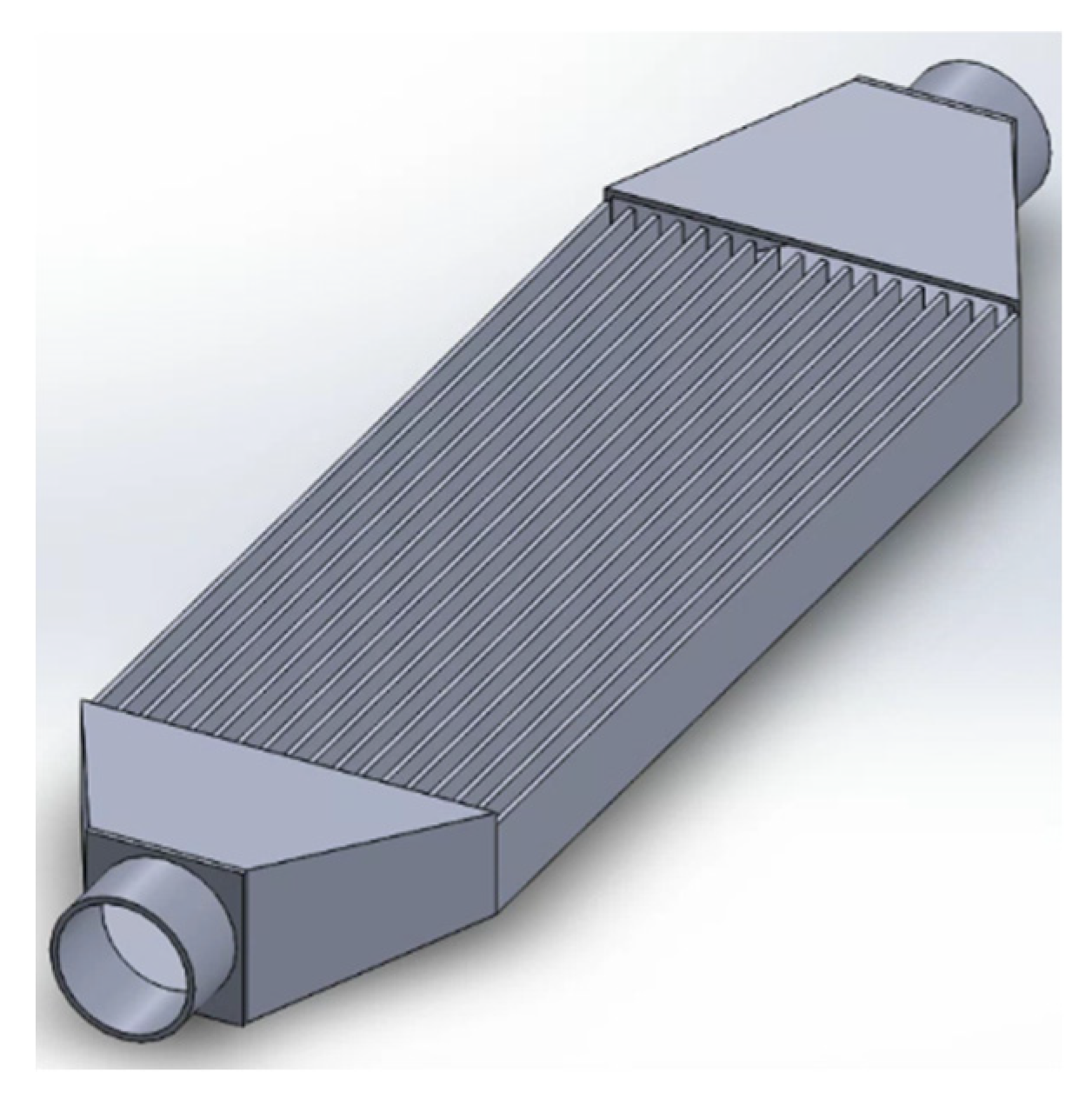
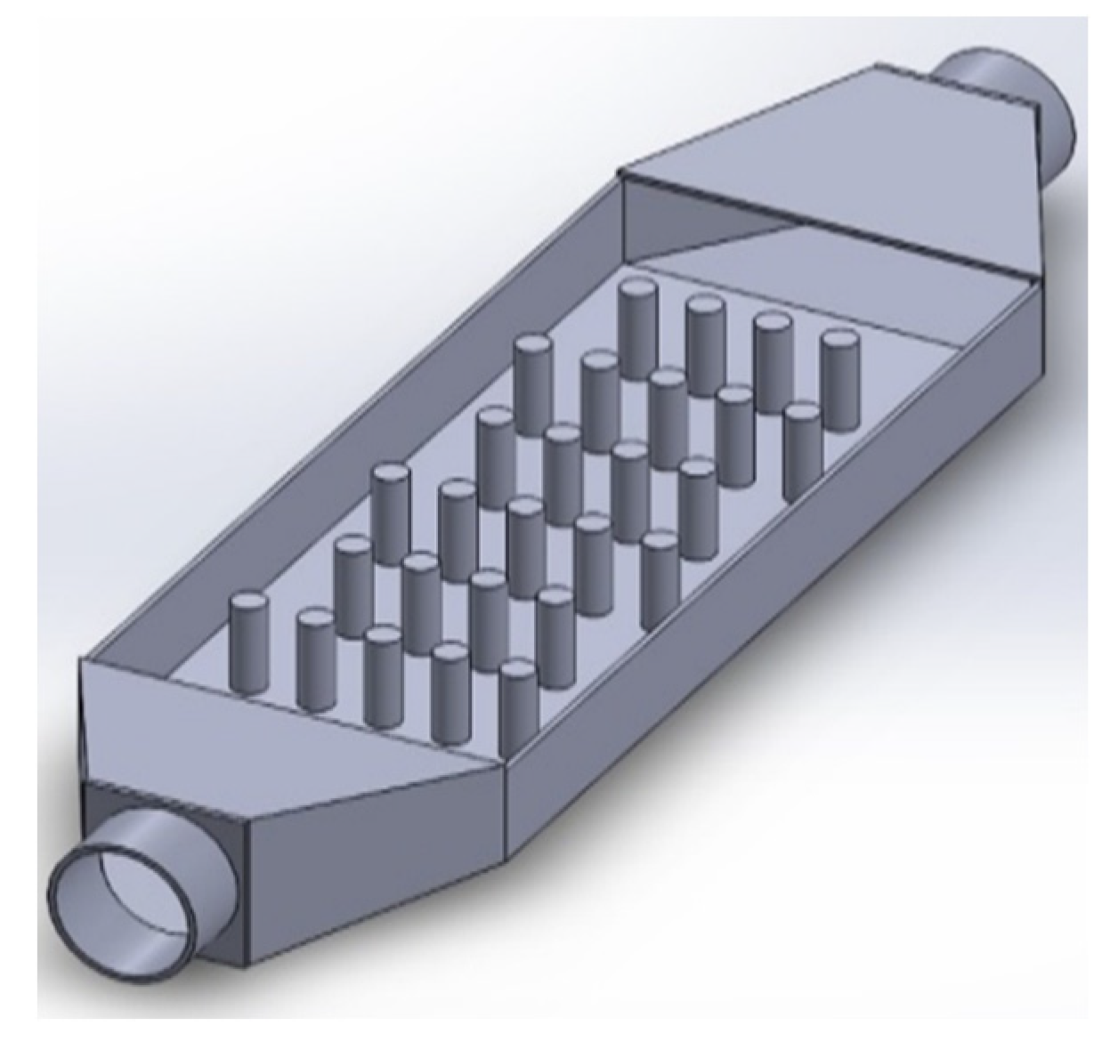
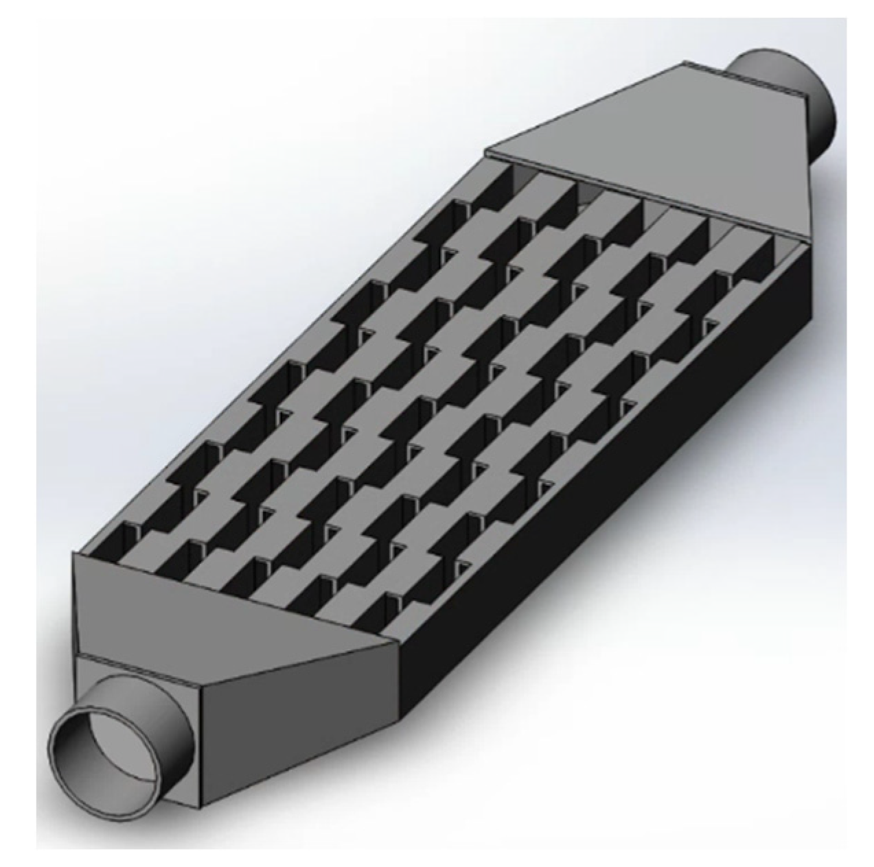
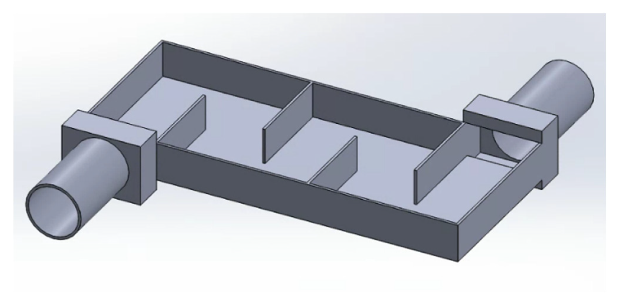
This study simulates five types of square heat exchangers. The types of heat exchangers include the cavity heat exchanger, plate-fin heat exchanger, pin fin heat exchanger, offset strip fin heat exchanger, and baffle plate heat exchanger. The central rectangular area of the heat exchanger for heat exchange is 227mm × 95mm × 24mm, and it has an inner diameter of 30mm for both the inlet and outflow. The shell material is made of steel. The plate fin heat exchanger features fins that are 1.5mm thick and spaced 4mm apart. The pin fin heat exchanger features a fin arrangement with a transverse spacing of 15mm and a longitudinal spacing of 30mm. The fin pitch, which refers to the distance between adjacent fins, is 8mm. The offset strip fin heat exchanger features a fin thickness measuring 1.5mm and a fin height of 19.5mm.
The fixed cooling system's square tube dimensions are 227mm × 95mm × 10mm. The tube is steel, and the cooling fluid used is water. The thermoelectric module utilizes a configuration where the chip is positioned on one side alone. The upper section comprises 10 thermoelectric chips arranged in series for thermoelectric conversion. Each chip is composed of 134 rectangular thermocouples. The dimensions of each thermoelectric element are 1.6mm (length) × 1.6mm (width) × 3mm (height), forming a rectangular shape. Figures 2 to 6 were created using Solidworks and examined in COMSOL [
19] software utilizing the finite element approach.
Figure 2.
Cavity heat exchanger [
20].
Figure 2.
Cavity heat exchanger [
20].
Figure 3.
Plate-fin heat exchanger [
20].
Figure 3.
Plate-fin heat exchanger [
20].
Figure 4.
Pin-fin heat exchanger [
20].
Figure 4.
Pin-fin heat exchanger [
20].
Figure 5.
Offset strip-fin heat exchanger [
20].
Figure 5.
Offset strip-fin heat exchanger [
20].
Figure 6.
Baffle-plate heat exchanger [
20].
Figure 6.
Baffle-plate heat exchanger [
20].
3.2. Simulation Conditions
In order to replicate the power generation of the ATEG in actual exhaust conditions, this work uses the gasoline engine employed in the experiments conducted by T.Y. Kim et al. [
21]. Simulation parameters are determined by selecting nine operational modes of the engine and using their related exhaust gas flow rates and temperatures. The precise simulation circumstances are outlined in
Table 1. The exhaust gas passes via the heat exchanger, where its thermophysical characteristics are simulated using air. The cooling system is designed with a mass flow rate of 0.06 kg/s and a temperature of 353K [
21], while the surrounding temperature is fixed at 298K.
3.3. Thermoelectric Materials
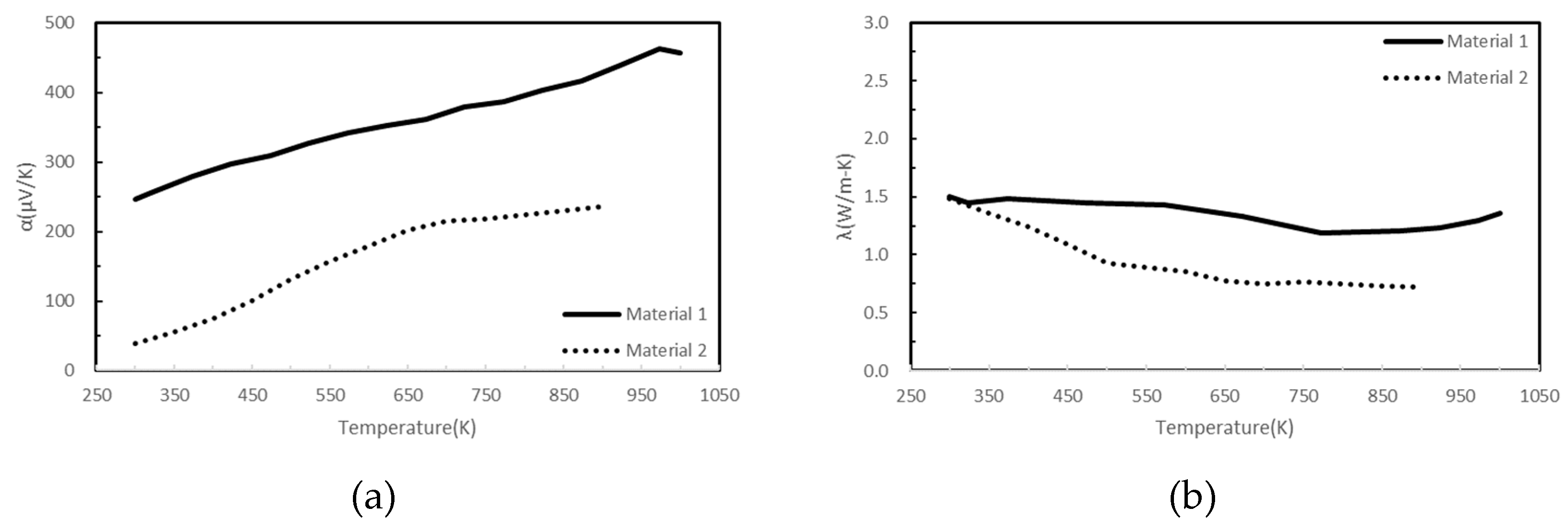
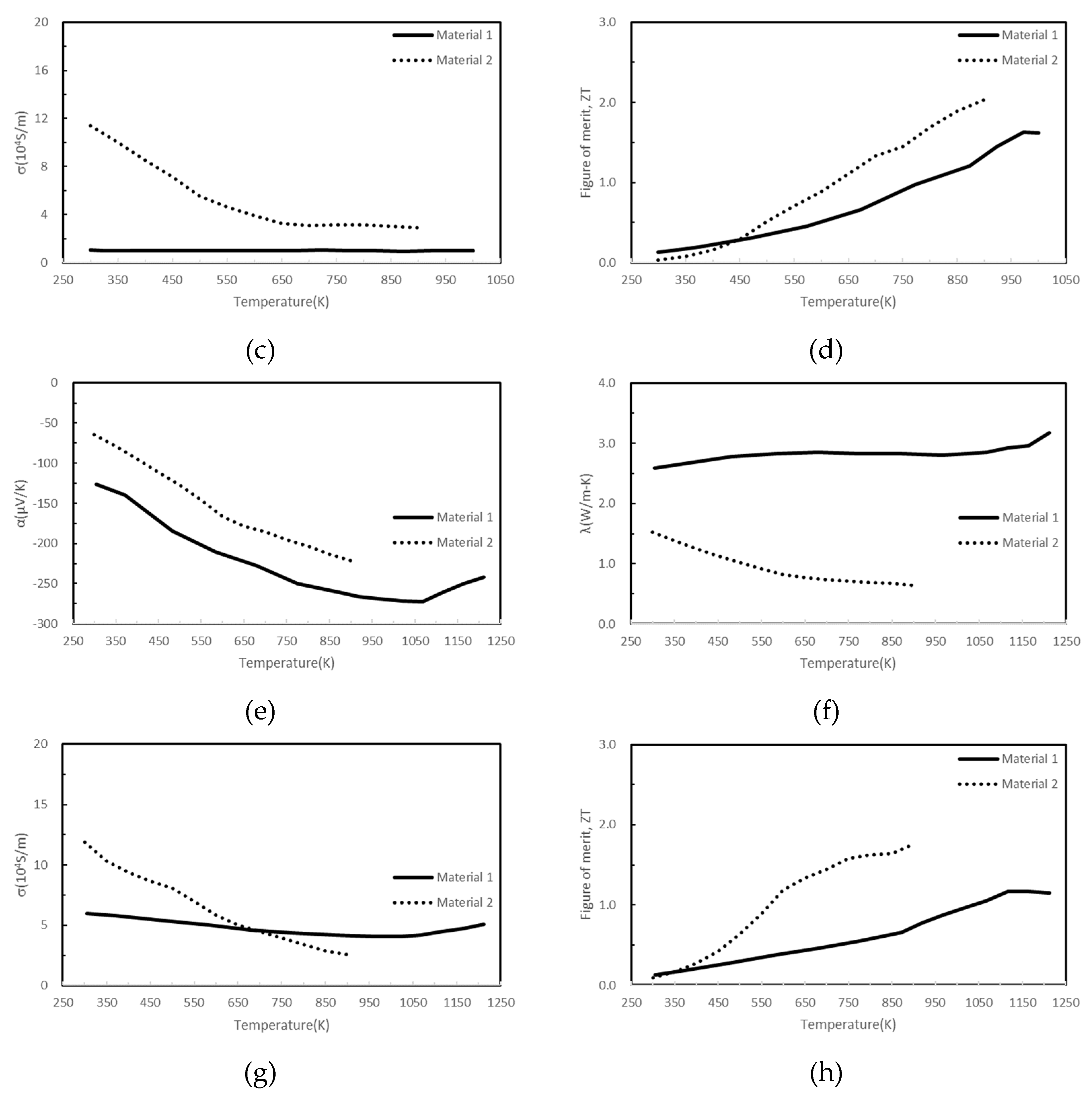
Considering the temperature differential between the cooling system and engine exhaust, materials with superior thermoelectric properties within the 300–1000K temperature range were selected. The study investigates the influence of diverse thermoelectric material features on power generation efficiency by selecting two sets of distinct thermoelectric materials. The initial group consists of a P-type thermoelectric material called Si
62Ge
31Au
4B
3 [
22], with a figure of merit (zT) value of 1.63. The second group comprises an N-type thermoelectric material composed of Si
0.88Ge
0.12 mixed with 5% FeSi
2 and 2.5% Ag [
23]. This material was sintered at 1000°C and achieved a zT value 1.20. The second group includes two types of thermoelectric materials. The first type is a P-type material called Pb
0.935Na
0.025Cd
0.04Se
0.5S
0.25Te
0.25 [
24], with a peak zT value of 2.00. The second type is an N-type material called Pb
0.89Sb
0.012Sn
0.1Se
0.5Te
0.25S
0.25 [
25], which has a zT value 1.80.
Figure 7 depicts the properties of the first set of thermoelectric materials as solid lines for Material 1 and the properties of the second set of thermoelectric materials as dotted lines for Material 2.
3.4. Boundary Condition
Different operating states of the engine and external environmental conditions affect the temperature distribution in the heat exchanger, leading to variations in the power generation of TEG chips. To maintain uniform boundary conditions in the simulation analysis, the following assumptions regarding physical properties were made:
The system operates in a steady state.
The fluid is incompressible and does not undergo a phase change.
Convective and radiative heat losses at the boundaries are neglected (adiabatic conditions).
Thermal contact resistances are neglected.
The cross-sectional areas and lengths of P-type and N-type thermoelectric materials are equal.
The power consumption of the cooling system pump is not considered.
The design of the clamping element is excluded from analysis.
4. Results and Discussion
When engine exhaust gas enters the heat exchanger, it increases the temperature of the heat exchanger's shell. The TEG chip and the heat exchanger shell are in direct contact, with the former acting as the hot side and the latter as the cold side about the TEG chip and the cooling system interface. The temperature difference causes the TEG chip to produce a voltage, which generates output power when connected to an external load resistance. This study is structured into three sections:
First, it examines the impact of various heat exchanger designs on the temperature distribution of the engine exhaust gas transmitted to the heat exchanger shell. It also explores the relationship between this temperature distribution and the electrical output of the TEG chip.
Second, it examines the influence of diverse engine operating conditions, distinguished by varying exhaust gas flow rates and temperatures, on the power output of different TEG modules.
Finally, by utilizing the TEG module at peak efficiency, the study investigates the impact of the thermoelectric material's zT value on the output power.
4.1. Analysis of the Influence of Heat Exchanger Design on Power Generation
In order to examine the temperature distribution and heat transfer properties of thermoelectric generators (TEGs) in heat exchangers with various designs, we implemented conditions corresponding to engine operation state number 1 from
Table 1. These conditions were applied to five different types of heat exchangers: the cavity heat exchanger, the plate fin heat exchanger, the pin fin heat exchanger, the offset strip fin heat exchanger, and the baffle plate heat exchanger.
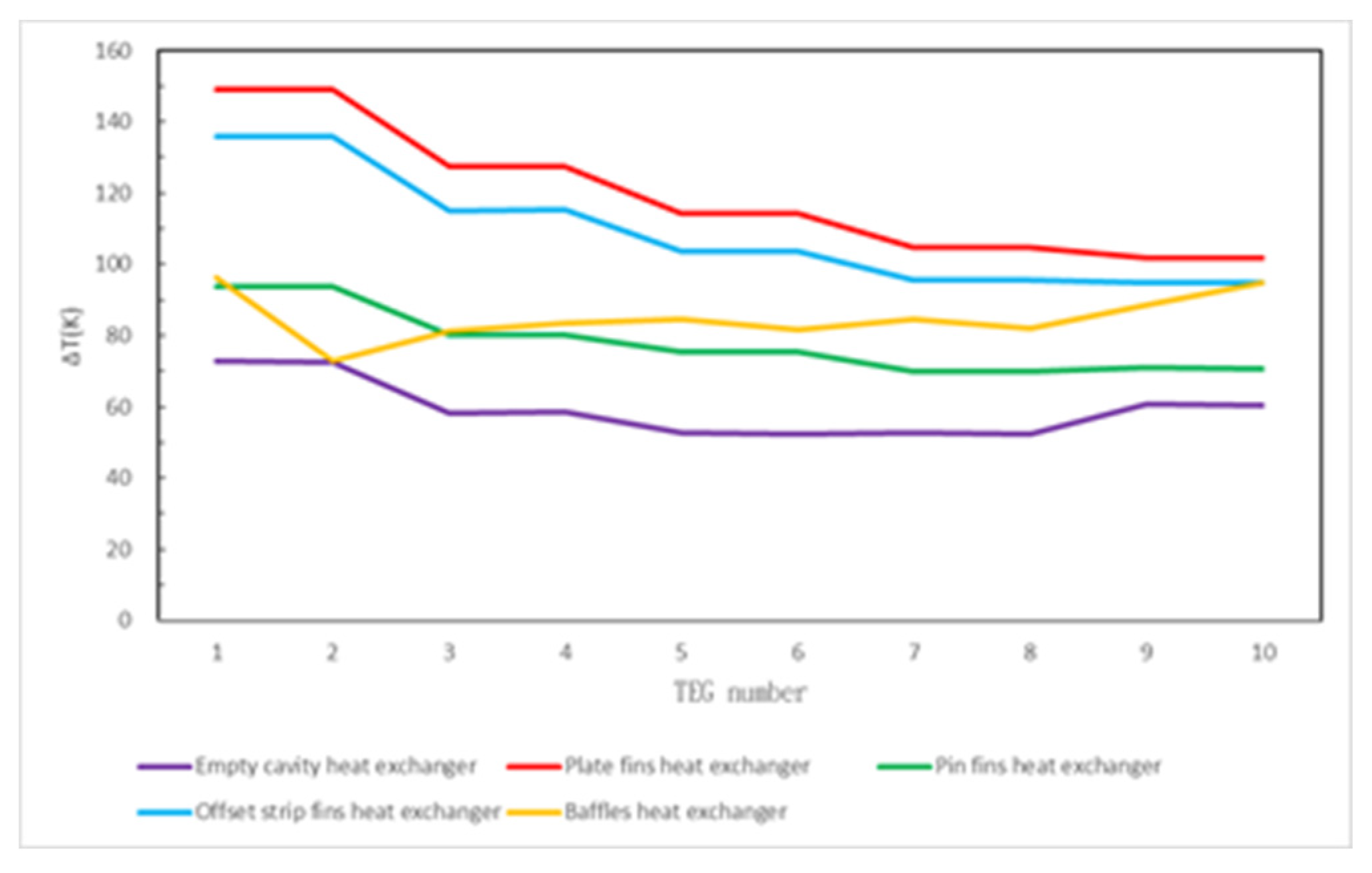
Figure 8 demonstrates that the internal fin design of heat exchangers substantially affects the supply of thermal energy for thermoelectric conversion in TEGs. Out of the four heat exchanger models with different fin designs, the plate pin heat exchanger demonstrates superior heat transmission properties, resulting in the greatest temperature differential in the TEG of up to 148.88K. The offset strip fin heat exchanger achieves a maximum temperature difference of 135.88K for the TEG. Both possess the shared characteristic of exhibiting fin designs. Conversely, the TEG in the cavity heat exchanger achieves a maximum temperature differential of only 72.72K, the lowest compared to the other variants.
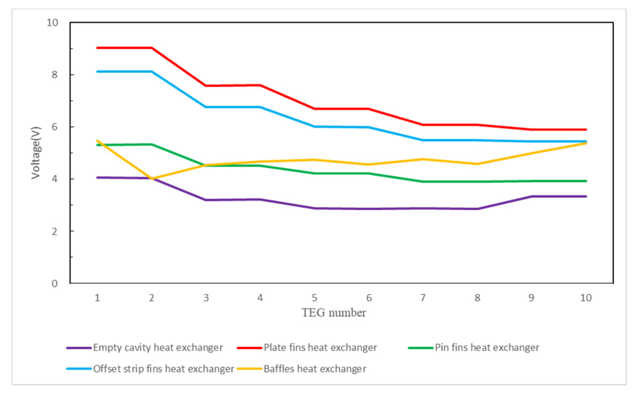
The voltage produced by the Seebeck effect in thermoelectric materials is determined by the product of the Seebeck coefficient, the number of thermocouple pairs, and the temperature difference. By using the temperature differences between the hot and cold ends of various heat exchangers, we model the voltage that TEGs produce. This is done by considering the Seebeck coefficient-temperature relationship of the thermoelectric materials, as shown in
Figure 7. Various temperature-difference conditions across different heat exchanger designs are simulated.
Figure 9 demonstrates a positive correlation between the TEG voltage and the temperature differential between the hot and cold ends.
The open-circuit voltage produced by each TEG chip is combined, and the current and output power are determined with the external load resistance. In this work, power generation efficiency was investigated to determine the impact of external load resistance. The TEG chips had a total internal resistance ranging from 177–182Ω across all temperature differential conditions. The narrow range is due to the minor change in the electrical conductivity of the selected thermoelectric materials with temperature. Hence, the external load resistance was adjusted within the range of 1-1000Ω, approximately five times greater than the internal resistance of the TEG chips, to investigate its impact on the output power.
When the engine is in state 1, the total output voltage and power of all chips connected in series are set by the properties of the thermoelectric materials, the external load resistance, and the sum of the open-circuit voltages of all the TEG chips.
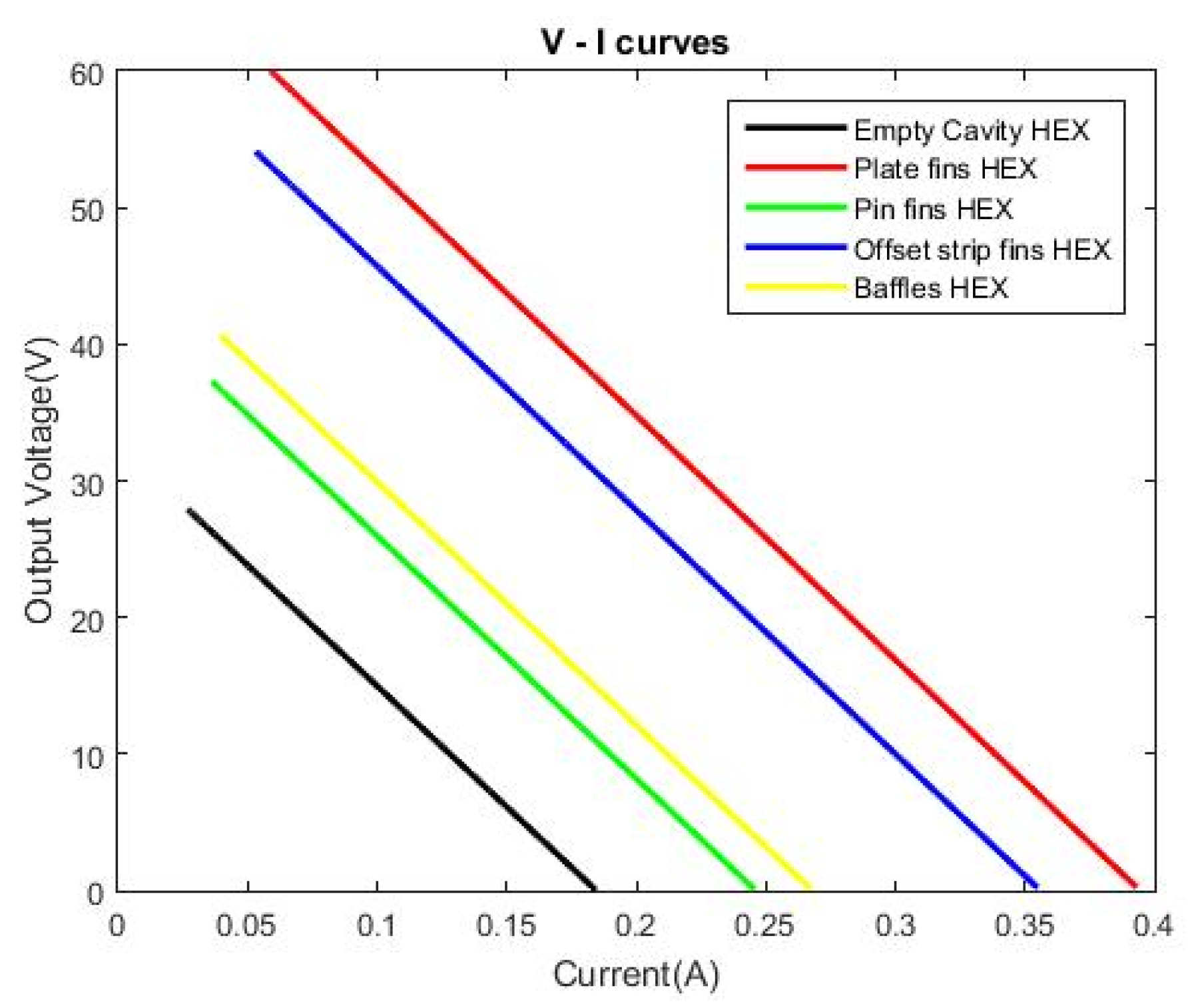
Figure 10 displays the voltage and current produced by the circuit when linked to five different TEG module types coupled to external load resistances varying from 1 to 1000Ω. As the external resistance increases, the current diminishes, elevating the output voltage and causing a diagonal distribution on the graph. Compared to
Figure 9, the plate fin heat exchanger exhibits the highest output voltage, whereas the empty cavity heat exchanger demonstrates the lowest.
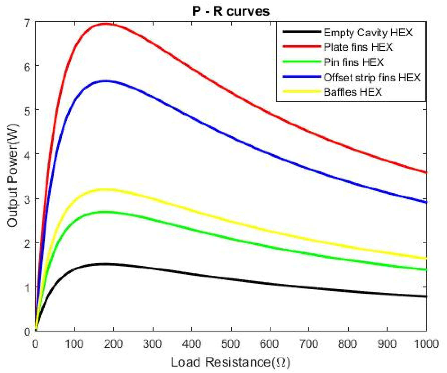
Figure 11 shows the output power of the five TEG module types for various external load resistances. The maximum values, ranging from 177.00 to 178.85Ω, match the total internal resistance of the TEG chips, confirming that maximum output power is achieved when the external load resistance equals the TEG chips’ internal resistance.
4.2. Evaluation of the Influence of Thermoelectric Materials on Power Generation Efficiency
This section analyzes the power output generated by TEG modules under nine distinct engine operating conditions while comparing identical operating states across multiple heat exchangers. The nine engine operating stages outlined in
Table 1 are utilized to ascertain the TEG modules' combined power output and overall efficiency.
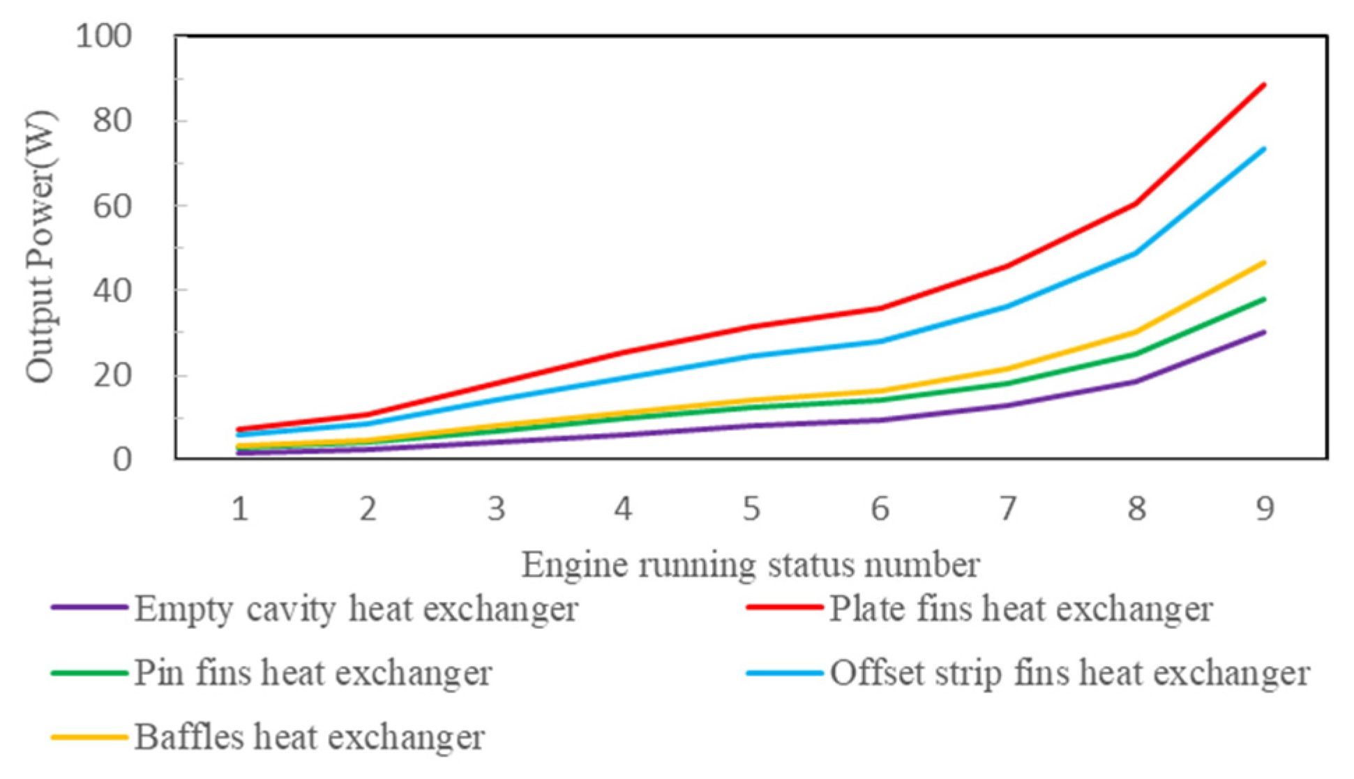
Figure 12 demonstrates that variations in engine load and heat exchanger design substantially impact the output power of each TEG module. As the engine load intensifies, the exhaust gas temperature also escalates, resulting in a more significant temperature differential between the hot and cold ends of the TEG chips and, consequently, higher power output. At maximum load, the Plate Fin Heat Exchanger achieves the highest output power of 86.30W, but the Cavity Heat Exchanger only provides a minimum power of 29.30W.
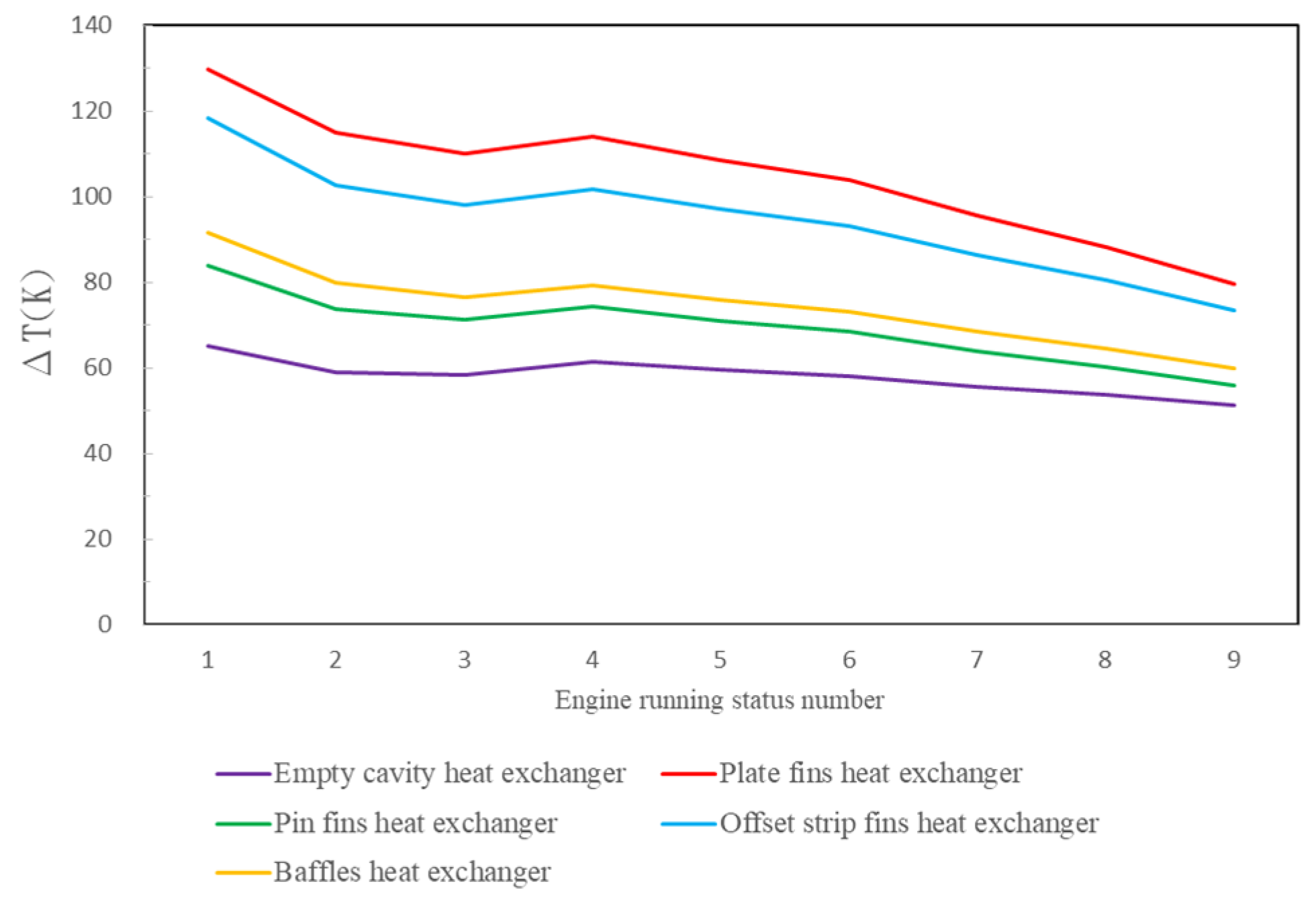
Figure 13 demonstrates that the temperature differential between the entrance and outlet ends of the cavity TEG module, through which engine exhaust gas passes, is minimal. The absence of internal fins in this heat exchanger layout enables the exhaust gas to flow rapidly through, resulting in little heat transfer. Conversely, the Plate Fin Heat Exchanger, featuring internal plate fins, reduces the velocity of exhaust gas flow between the fins due to boundary layer effects. Furthermore, the plate fins facilitate additional heat transfer, leading to the most significant temperature differential between the inlet and exit. Although the exhaust gas temperature rises with the engine load, the temperature differential between the heat exchanger inlet and outlet decreases as the load increases. This leads to a more uniform temperature at the TEG hot end, enabling higher power output.
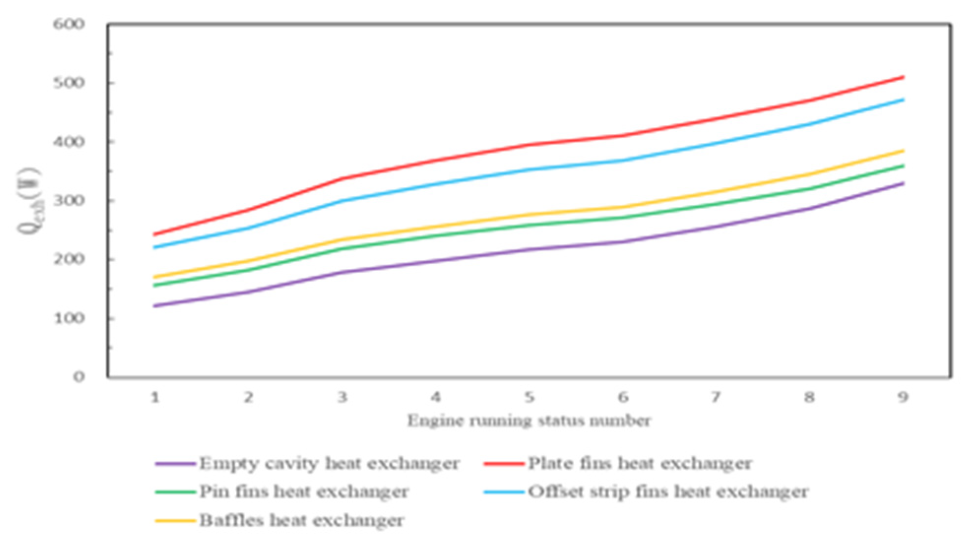
Figure 13 illustrates the temperature difference between the engine exhaust gas at the heat exchanger inlet and outlet, observed under various engine operating conditions. The heat available for the thermoelectric generator (TEG) under different engine loads can be determined using this temperature difference, as shown in
Figure 14. Incorporating plate fins in the exhaust gas heat exchanger significantly improves heat transfer to the TEG. In all heat exchanger models with plate fins, more heat is transmitted to the TEG than the cavity model. Among these, the Plate Fin Heat Exchanger delivers the highest heat to the TEG, reaching a maximum of 511 W at full engine load. In contrast, the Cavity TEG only transfers 330 W of heat.
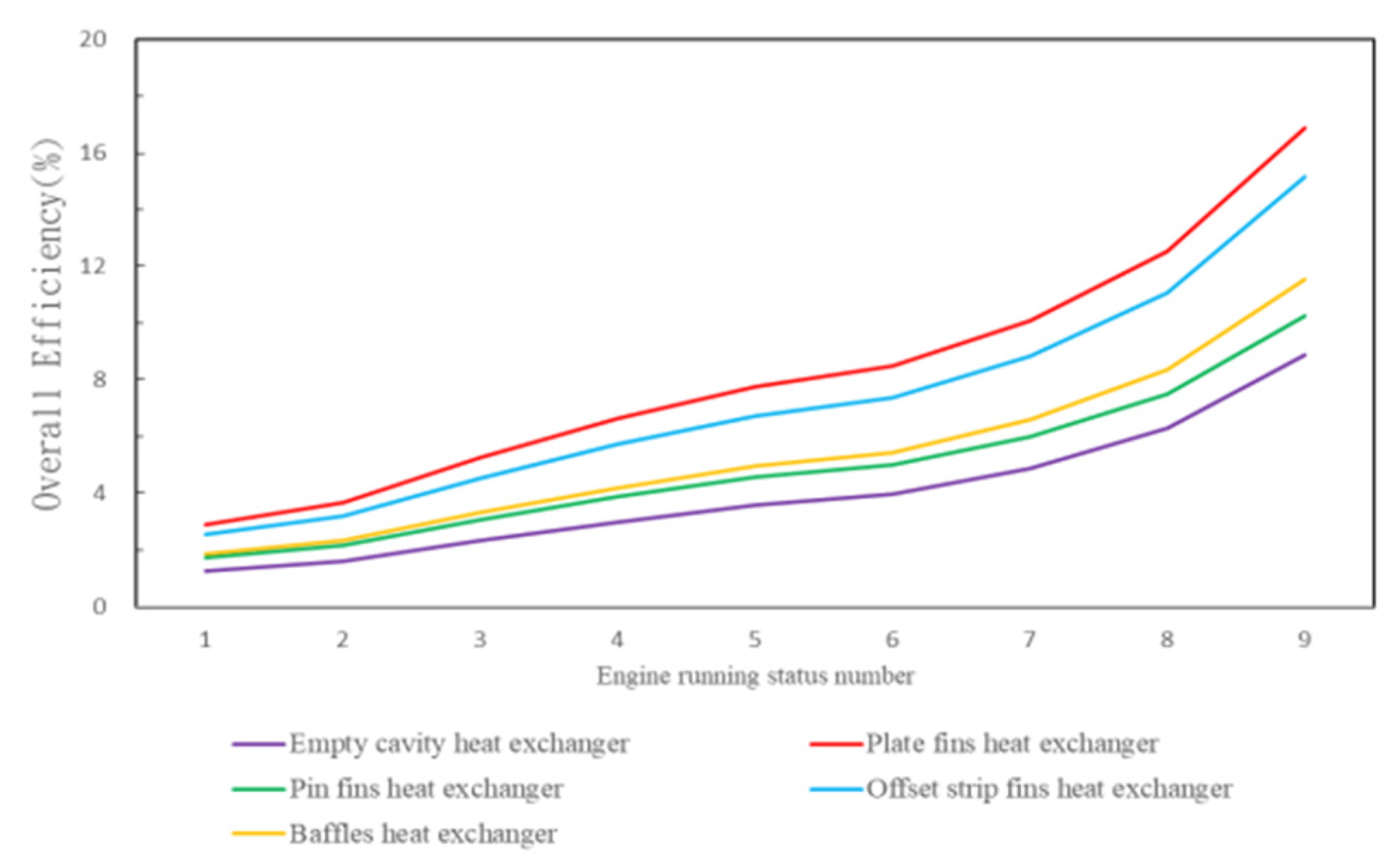
he TEG module's total efficiency
η is the ratio of the TEG's output power to the heat it gets from the engine's exhaust gas.
Figure 15 shows that as the engine loads up, the total efficiency of the TEG module goes up. The plate-fin heat exchanger utilizes plate fins to enhance flow dispersion and heat transfer, improving performance. This enhanced design allows the TEG chips to produce electricity using a more significant temperature differential, yielding the highest total efficiency.
The heat recovery efficiency (
ηHR) [
20] quantifies the total exhaust gas heat utilized by the TEG module. It is determined by the ratio of the TEG's maximum possible heat input to its actual heat output and can be mathematically represented as:
The plate-fin heat exchanger is utilized to examine the influence of engine operating conditions on heat recovery efficiency due to its superior output power and total efficiency. The heat recovery efficiency is calculated using the temperature difference between the inlet and outlet of the heat exchanger, as well as the inlet temperature parameters of the engine exhaust gas from
Table 1.
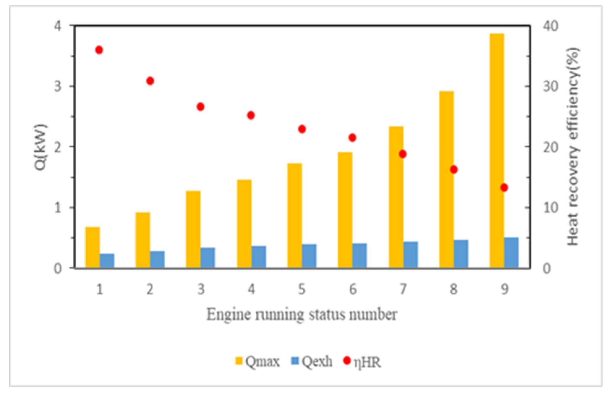
Figure 16 demonstrates that as the engine load increases, the exhaust gas flow rate and heat content rise due to higher temperatures. As a result, the maximum possible heat input to the TEG module increases significantly with load, from 0.68 to 3.87 kW. However, the heat transferred to the TEG module has a minor increase, ranging from 0.24 to 0.51 kW. Comparing these thermal values shows that heat recovery efficiency progressively decreases as engine load rises. While exhaust gas contains much heat, the flow quickly removes it rather than using it for the TEG. The red dots in
Figure 16 show that heat recovery efficiency declines with higher loads, falling from 35.90% to 13.19%.
When building thermoelectric generator (TEG) modules for engine waste heat recovery, it is crucial to consider the pressure drop as a significant parameter. A large pressure drop signifies that the engine exhaust gas cannot exit the heat exchanger effectively, leading to back pressure that negatively affects the efficiency and lifespan of the engine. In automotive waste heat recovery systems, TEG modules typically have an acceptable pressure drop of 3 kPa or less [
20]. Pressure losses arise when engine exhaust gas enters the heat exchanger, resulting from fluid expansion and contraction and friction between the fluid and the heat exchanger shell. Moreover, including fin designs in the heat exchanger unavoidably results in supplementary losses as the fluid passes over the fins. This issue is investigated by doing simulation analysis on several thermoelectric generator (TEG) modules while considering various engine operating circumstances. The analysis examines the pressure drop that occurs when engine exhaust gas passes through the heat exchanger.
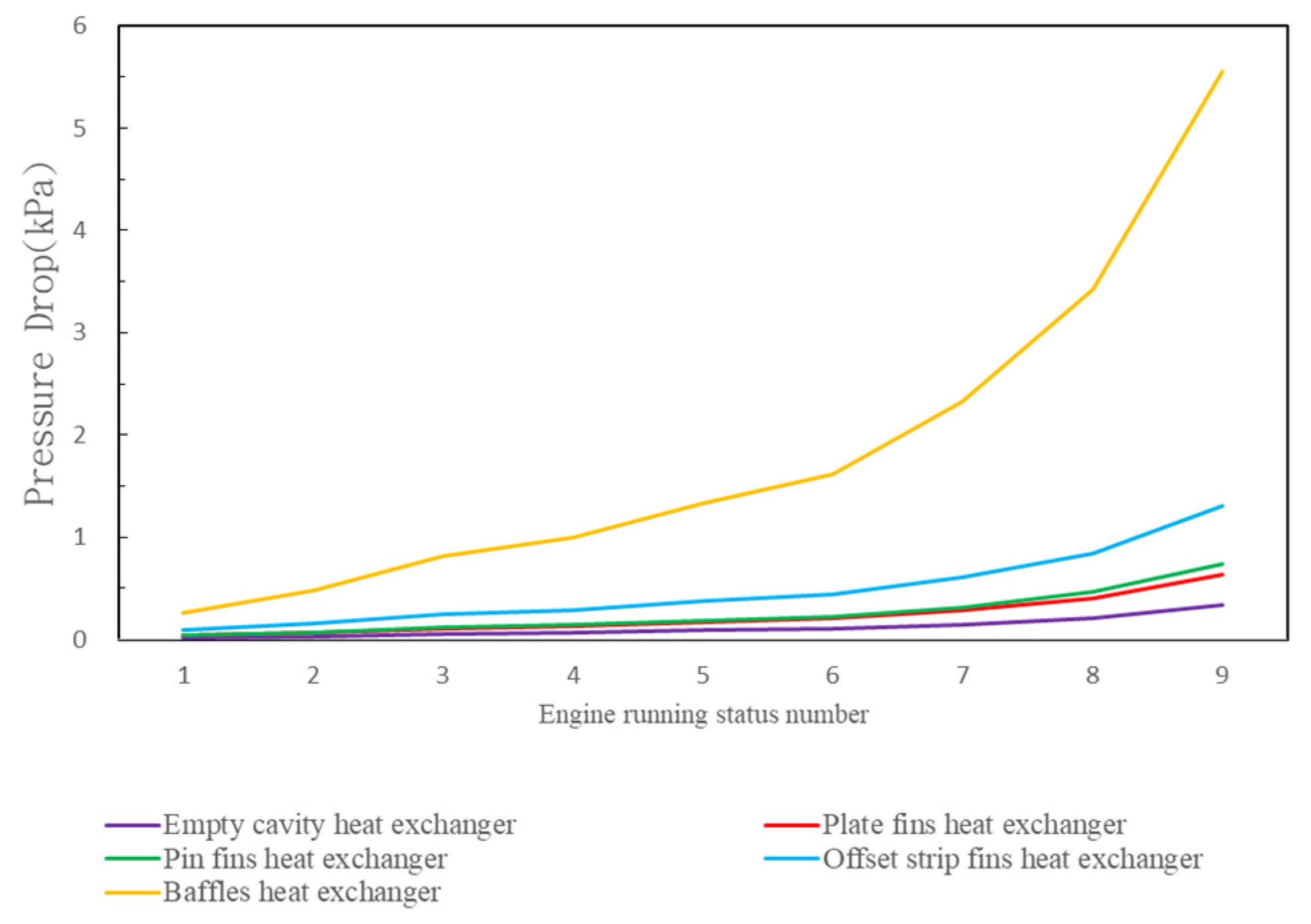
Figure 17 demonstrates that the cavity heat exchanger, without internal fin designs, experiences the lowest pressure drop. The pressure loss reaches 0.34 kPa while the engine operates at full load. The pressure decreases in the plate fins, pin fins, and offset strip fin heat exchangers are greater than those in the cavity model, measuring 0.63 kPa, 0.74 kPa, and 1.31 kPa, respectively. The main cause of this is the decrease in pressure at the entrance and exit, as well as the resistance encountered along the walls and fins of the chamber. The pressure loss is considerably more significant for the baffle plate heat exchanger than other heat exchangers. This is primarily due to boundary layer separation and secondary flow from internal turns.
Figure 17 illustrates that the pressure loss in the baffle plate heat exchanger is remarkably high, peaking at 5.56 kPa during maximum engine load. Hence, the baffle plate design is not well-suited for TEG modules.
In the exploration of the output power of Thermoelectric Generator (TEG) modules, it is essential to consider the pump loss power
generated by the pressure drop of the engine exhaust gas. This consideration allows for an assessment of the net output power that the entire TEG module system can achieve. The relationship can be expressed by the following formula:
Similar to
Figure 17,
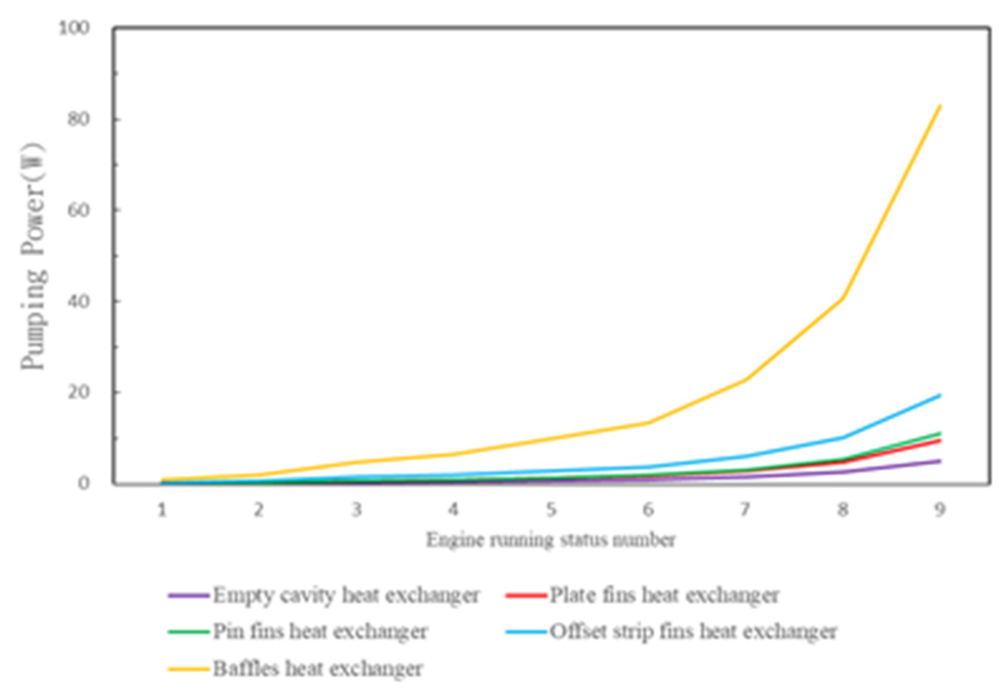
Figure 18 shows that as engine load increases, the pressure drop caused by exhaust gas rises, resulting in higher engine pump power loss. The overall pattern closely matches that of the pressure drop. Without internal fins, the cavity heat exchanger has the lowest pressure drop and pump power loss, reaching 5.05W at peak load. In contrast, the baffle plate heat exchanger exhibits the highest pump power, peaking at 82.88 W.
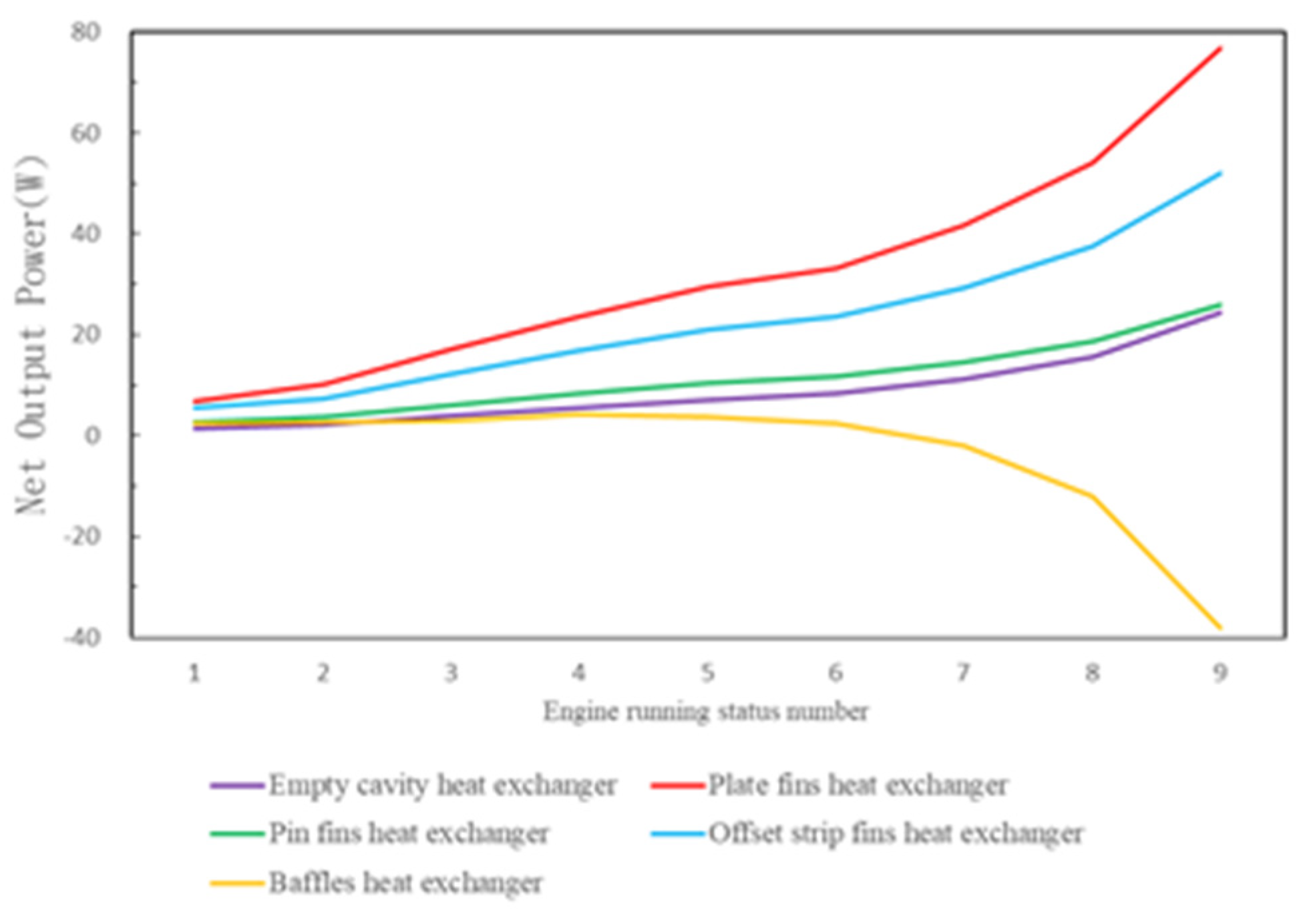
Figure 19 illustrates that rising engine loads increase heat exchanger pressure drops from the exhaust gas, proportionally elevating pump power loss. The cavity, plate-fin, pin fins, and offset strip fin heat exchangers have pressure drops below 1.31 kPa and pump losses under 19.47 W. As a result, their TEG net output power rises with load, albeit less steeply than in
Figure 12. However, the baffle plate heat exchanger experiences significant pressure drops from its structure bends, requiring substantial pumping to propel exhaust gas. Since TEG power generation is low, net output power stays above zero for the first six engine states but becomes negative at higher loads when pump power exceeds TEG output. At maximum load, the net output is -38.31W, indicating TEG power from the temperature differential cannot compensate for pump losses. The baffle plate heat exchanger TEG module is ineffective for waste heat recovery and unsuitable for application.
4.3. Analysis of the Influence of Engine Operating Conditions on Power Generation
Thermoelectric material selection significantly impacts TEG module power generation efficiency. Considering engine operating conditions, this section investigates how enhanced thermoelectric material performance affects efficiency. The dimensionless thermoelectric figure of merit,
, has three areas for improvement: increasing the Seebeck coefficient, improving electrical conductivity, and minimizing thermal conductivity. Jointly optimizing these enhances efficiency. As
Figure 7 shows, superior materials have a lower Seebeck coefficient but reduced thermal conductivity and higher electrical conductivity. Consequently, the ZT value rises from 1.63 to 2.0 for P-type and 1.2 to 1.8 for N-type materials, increasing output power. According to
Table 1, automakers regard engine state eight as the most frequent operating condition [
20]. We apply this state to examine material influences on different TEG modules. Simulation of TEG chips involves integrating both material sets to determine temperature distribution and voltage. Output power for each TEG module is calculated via thermoelectric theory.
Figure 20 shows that improved materials yield higher output power in all TEG modules. Heat exchanger internal fin configuration, impacting shell temperature distribution, also plays a role. The output power difference between TEG modules with the two material sets, depicted by ∆W in
Figure 20, has the most significant increase with the plate-fin design and the least with the cavity. This occurs because the materials have higher efficiency at elevated temperatures. The total output power increase is more significant with lower TEG chip thermal conductivity and higher hot-end temperatures.
5. Conclusions
This study employs COMSOL modeling to investigate waste heat recovery using thermoelectric (TE) interlayers. It examines how different internal fin designs of heat exchangers affect the performance of thermoelectric generator (TEG) modules. The analysis focuses on how varied engine operating conditions, such as exhaust gas flow and temperature fluctuations, impact TEG module performance. Furthermore, it evaluates the influence of different thermoelectric material combinations on electricity production. Based on the simulation findings, the following conclusions are drawn:
The data comparison in
Figure 11 shows that incorporating fins in heat exchangers greatly improves heat transfer over cavity designs, increasing TEG chip power generation. The plate-fin heat exchanger evenly spreads the flow and temperature of the exhaust gas inside its shell. This produces the most power when the input conditions are perfect, especially when the external load resistance is the same as the chip's internal resistance.
As shown in
Figure 15, higher engine loads increase exhaust gas flow and temperature, enabling more heat transfer to the TEG and higher power generation. However, under low loads, limited performance enhancement occurs. Thus, waste heat recovery is most efficient at high loads.
Power generation varies when combining different heat exchangers and engine operating conditions in TEG modules. The plate-fin heat exchanger enables the most significant temperature differential and highest TEG output power due to exceptional heat transfer. Compared to other designs, this TEG module has an average output power 290% higher than the cavity, 155% higher than the pin-fin, 27% higher than the offset strip fin, and 117% higher than baffle plate across various engine conditions.
When constructing waste heat recovery systems, pressure drop must be considered. Higher engine loads increase exhaust gas pressure drops through the TEG, necessitating more pumping power and less power output.
Figure 19 shows that the baffle plate heat exchanger causes severe pressure drops at high loads, leading to negative net output power, while other designs have reduced drops and closely match output power.
The plate-fin heat exchanger is the most suitable for engine waste heat recovery of the examined models.
Figure 20 shows that the second thermoelectric material group has a lower Seebeck coefficient and voltage but higher electrical conductivity, decreasing TEG internal resistance and increasing output power. This demonstrates that thermoelectric material progress significantly enhances power generation.
Author Contributions
Conceptualization, C.-I W. and C.-Y C.; methodology, C.-I W. and C.-Y C.; software, C.-Y C.; validation, C.-Y C.; formal analysis, C.-I W. and C.-Y C.; investigation, C.-I W. and C.-Y C..; resources, C.-I W.; data curation, C.-Y C.; writing—original draft preparation, C.-I W., K-W D., Y.-C. C and C.-Y C.; writing—review and editing, C.-I W.; visualization, C.-Y C.; supervision, C.-I W.; project administration, C.-I W.; funding acquisition, C.-I W. All authors have read and agreed to the published version of the manuscript.
Funding
This research was funded by National Science and Technology Council of Taiwan, grant number 109-2221-E-019 -013 -.
Data Availability Statement
Data can be obtained by contacting the author, Chun-I Wu (wuchuni@ntou.edu.tw).
Acknowledgments
The authors would like to thank the reviewers for their comments on improving the quality of the paper.
Conflicts of Interest
The authors declare no conflict of interest.
References
- C.-T. Hsu, G.-Y. Huang, H.-S. Chu, B. Yu, and D.-J. Yao, "Experiments and simulations on low-temperature waste heat harvesting system by thermoelectric power generators," Applied Energy, vol. 88, no. 4, pp. 1291-1297, 2011. [CrossRef]
- T. A. Horst, H.-S. Rottengruber, M. Seifert, and J. Ringler, "Dynamic heat exchanger model for performance prediction and control system design of automotive waste heat recovery systems," Applied Energy, vol. 105, pp. 293-303, 2013. [CrossRef]
- C. Suter, Z. Jovanovic, and A. Steinfeld, "A 1 kWe thermoelectric stack for geothermal power generation–Modeling and geometrical optimization," Applied energy, vol. 99, pp. 379-385, 2012. [CrossRef]
- A. Royale, M. Simic, and P. Lappas, "Engine exhaust manifold with thermoelectric generator unit," International Journal of Engine Research, vol. 22, no. 7, pp. 2180-2188, 2021. [CrossRef]
- F. Albatati and A. Attar, "Analytical and experimental study of thermoelectric generator (TEG) system for automotive exhaust waste heat recovery," Energies, vol. 14, no. 1, p. 204, 2021. [CrossRef]
- M. S. Omar, B. Singh, and M. F. Remeli, "Motorcycle Waste Heat Energy Harvesting Using Thermoelectric Generators," Journal of Electronic Materials, vol. 49, pp. 2838-2845, 2020. [CrossRef]
- Y. Choi, A. Negash, and T. Y. Kim, "Waste heat recovery of diesel engine using porous medium-assisted thermoelectric generator equipped with customized thermoelectric modules," Energy Conversion and Management, vol. 197, p. 111902, 2019. [CrossRef]
- Y. Wang, S. Li, X. Yang, Y. Deng, and C. Su, "Numerical and experimental investigation for heat transfer enhancement by dimpled surface heat exchanger in thermoelectric generator," Journal of electronic materials, vol. 45, pp. 1792-1802, 2016. [CrossRef]
- S. Ezzitouni, P. Fernández-Yáñez, L. Sánchez, and O. Armas, "Global energy balance in a diesel engine with a thermoelectric generator," Applied Energy, vol. 269, p. 115139, 2020. [CrossRef]
- X. Liu, Y. Deng, S. Chen, W. Wang, Y. Xu, and C. Su, "A case study on compatibility of automotive exhaust thermoelectric generation system, catalytic converter and muffler," Case Studies in Thermal Engineering, vol. 2, pp. 62-66, 2014.
- R. C. Kumar, A. Sonthalia, and R. Goel, "Experimental study on waste heat recovery from an IC engine using thermoelectric technology," Thermal science, vol. 15, no. 4, pp. 1011-1022, 2011. [CrossRef]
- L. Lin, Y.-F. Zhang, H.-B. Liu, J.-H. Meng, W.-H. Chen, and X.-D. Wang, "A new configuration design of thermoelectric cooler driven by thermoelectric generator," Applied Thermal Engineering, vol. 160, p. 114087, 2019. [CrossRef]
- Y. Feng, L. Chen, F. Meng, and F. Sun, "Thermodynamic analysis of TEG-TEC device including influence of Thomson effect," Journal of Non-Equilibrium Thermodynamics, vol. 43, no. 1, pp. 75-86, 2018. [CrossRef]
- T. H. Kwan, X. Wu, and Q. Yao, "Complete implementation of the combined TEG-TEC temperature control and energy harvesting system," Control Engineering Practice, vol. 95, p. 104224, 2020. [CrossRef]
- C. Liu, X. Pan, X. Zheng, Y. Yan, and W. Li, "An experimental study of a novel prototype for two-stage thermoelectric generator from vehicle exhaust," Journal of the Energy Institute, vol. 89, no. 2, pp. 271-281, 2016. [CrossRef]
- R. Quan, G. Liu, C. Wang, W. Zhou, L. Huang, and Y. Deng, "Performance investigation of an exhaust thermoelectric generator for military SUV application," Coatings, vol. 8, no. 1, p. 45, 2018. [CrossRef]
- Q. Du, H. Diao, Z. Niu, G. Zhang, G. Shu, and K. Jiao, "Effect of cooling design on the characteristics and performance of thermoelectric generator used for internal combustion engine," Energy Conversion and Management, vol. 101, pp. 9-18, 2015. [CrossRef]
- K. M. Saqr, M. K. Mansour, and M. Musa, "Thermal design of automobile exhaust based thermoelectric generators: Objectives and challenges," International Journal of Automotive Technology, vol. 9, pp. 155-160, 2008. [CrossRef]
- "COMSOL Multiphysics." https://www.comsol.com/ (accessed 20 November 2023, 2023).
- C.-Y. Chen, "Analysis of thermoelectric generators applied to waste heat recovery," Master of science, Mechanical and Mechatronic Engineering, National Taiwan Ocean University, Keelung, Taiwan, Republic of China, 2021.
- T. Y. Kim, J. Kwak, and B.-w. Kim, "Application of compact thermoelectric generator to hybrid electric vehicle engine operating under real vehicle operating conditions," Energy conversion and management, vol. 201, p. 112150, 2019. [CrossRef]
- O. Muthusamy et al., "Enhancement of the thermoelectric performance of Si-Ge nanocomposites containing a small amount of Au and optimization of boron doping," Journal of Electronic Materials, vol. 49, pp. 2813-2824, 2020. [CrossRef]
- A. Nozariasbmarz, Z. Zamanipour, P. Norouzzadeh, J. S. Krasinski, and D. Vashaee, "Enhanced thermoelectric performance in a metal/semiconductor nanocomposite of iron silicide/silicon germanium," RSC advances, vol. 6, no. 55, pp. 49643-49650, 2016. [CrossRef]
- B. Jiang et al., "Entropy engineering promotes thermoelectric performance in p-type chalcogenides," Nature communications, vol. 12, no. 1, p. 3234, 2021. [CrossRef]
- B. Jiang et al., "High-entropy-stabilized chalcogenides with high thermoelectric performance," Science, vol. 371, no. 6531, pp. 830-834, 2021. [CrossRef]
|
Disclaimer/Publisher’s Note: The statements, opinions and data contained in all publications are solely those of the individual author(s) and contributor(s) and not of MDPI and/or the editor(s). MDPI and/or the editor(s) disclaim responsibility for any injury to people or property resulting from any ideas, methods, instructions or products referred to in the content. |
© 2024 by the authors. Licensee MDPI, Basel, Switzerland. This article is an open access article distributed under the terms and conditions of the Creative Commons Attribution (CC BY) license (http://creativecommons.org/licenses/by/4.0/).
