This paper develops and extends ideas that were initially partially presented at two conferences: IWAA’23 [
1], IPAC’24 [
2] and at the Airbus Tolerancing Days [
3].
1. Introduction
“Then, Socrates, we will “align the axis of the magnet with an accuracy of 50 microns”.
– This is a good thing, Timaios, and I congratulate you for this nice plan. Just tell me, what do you mean by axis of the magnet, the one that you wish to handle?
– It is a straight line, Socrates, that, as you see, just stands right in the middle of the magnet like in drawing.
– Ô Timaios, I do not see anything in the middle of the magnet. What are you looking at, for Zeus sake?
– Worshipful Socrates, this is the axis of the cylinder where later on will the beam pipe be installed, easy!
– Really? How do you define it? Are you sure it is unique?
The Pythagorician geometrist Timaios, from Plato’s famous work
Timaios, was of course not working with magnets and beam pipes. Socrates’ questions are albeit more than relevant to understand the operational requirement stated by Timaios, formulated in the exact terms that can be found in almost every paper dealing with installation and alignment of modern scientific facilities based on particle beam physics [
4,
5,
6,
7,
8].
There are usually glitches between the worlds of functional specification, design, manufacturing, metrology, survey and alignment. Some make systematic use of coordinate systems, some think in terms of reference frame attached to the machine-tool, some other use planes and straight lines as datums.
“Then, with respect to what will you align this invisible middle-of-the-cylinder-deemed-straight-line?”
This question of the reference frame is central. The notion of datum features and their distinction with datum systems in GPS terms [
9] (or with datum reference frames according to ASME wording [
10]) helps clarify some issues, but these tools are incomplete and the process to establish them is somehow perceived as rather complex by many designers; and they are hardly used in the survey and alignment word. Thus, any functional requirements formalised by using datum systems are not directly understood and introduce ambiguities in requirements (known as specification uncertainties).
This paper aims at clarifying the meaning of such requirements and providing practical tools for all stakeholders involved along the lifecycle of any device installed along the beam. The goal is to ensure a unique and common understanding of how the functional features are identified and how their situation (meant as the combination of both the position and the orientation of the device, defining the six degrees of freedom of its free rigid body motion) is handled [
11], from the need to the commissioning and operation.
More generically, the paper explores the notion of mutual situation between two features, and provides new tools to parametrize this mutual situation, using the concept of situation features introduced in ISO GPS series [
12]. This parametrization allows for a systematic analysis of the variations of both position and orientation along the lifecycle of each component: design, manufacturing, measurement and fiducialization (measurement of the position and orientation of the functional features with respect to external marks visible during installation by the survey equipment), and at last, installation after allocation to a given functional slot of a given component.
From the operational (industrial) point of view, the paper presents the results developed inside the European Spallation Source (ESS, Lund, Sweden) for the definition of generic drawings of any component for three of the main phases of their lifecycle: functional specification (that can then be transformed into manufacturing specification and into verification specification of the manufactured part [
13]); fiducialization specification (defined as the instruction on which characteristics to measure and report); and installation specification (a generalized type of assembly drawing, using the results of fiducialization to establish the targeted position). These findings are not restricted to Big Science beam-based facilities, the context of their development, and are generic enough to be extendable to any kind of complex assembly at any scale, from high accuracy watch industry to aerospace industry, passing by automotive or aeronautic industry).
From the research point of view, the paper establishes a couple of new concepts that are the basis for revisiting the fundamental concepts of the ISO GPS [
12], or of similar geometrical product specifications systems like ASME GD&T [
10]:
systematic definition of situation features, use and handling of the situation features defined by the invariance class to which the functional features belong;
extension of the operation of the association to the case of non-geometrical functional features (e. g. electric or magnetic features);
introduction of the use of contacting features as toleranced features;
proper handling of the situation of the collection of two features;
More perspectives of this paper are exposed in conclusion, in particular the handling of the collection of any number of features, and the extension of invariance classes to deal with contacting features whose degrees of freedom are not all locked.
2. Reflections on the meaning of an axis alignment requirement
2.1. Geometrical real axis of a cylinder
This subsection aims at highlighting the traps hidden behind the simple term of “geometrical axis”. Which kind of straight line are we speaking of when using this term?
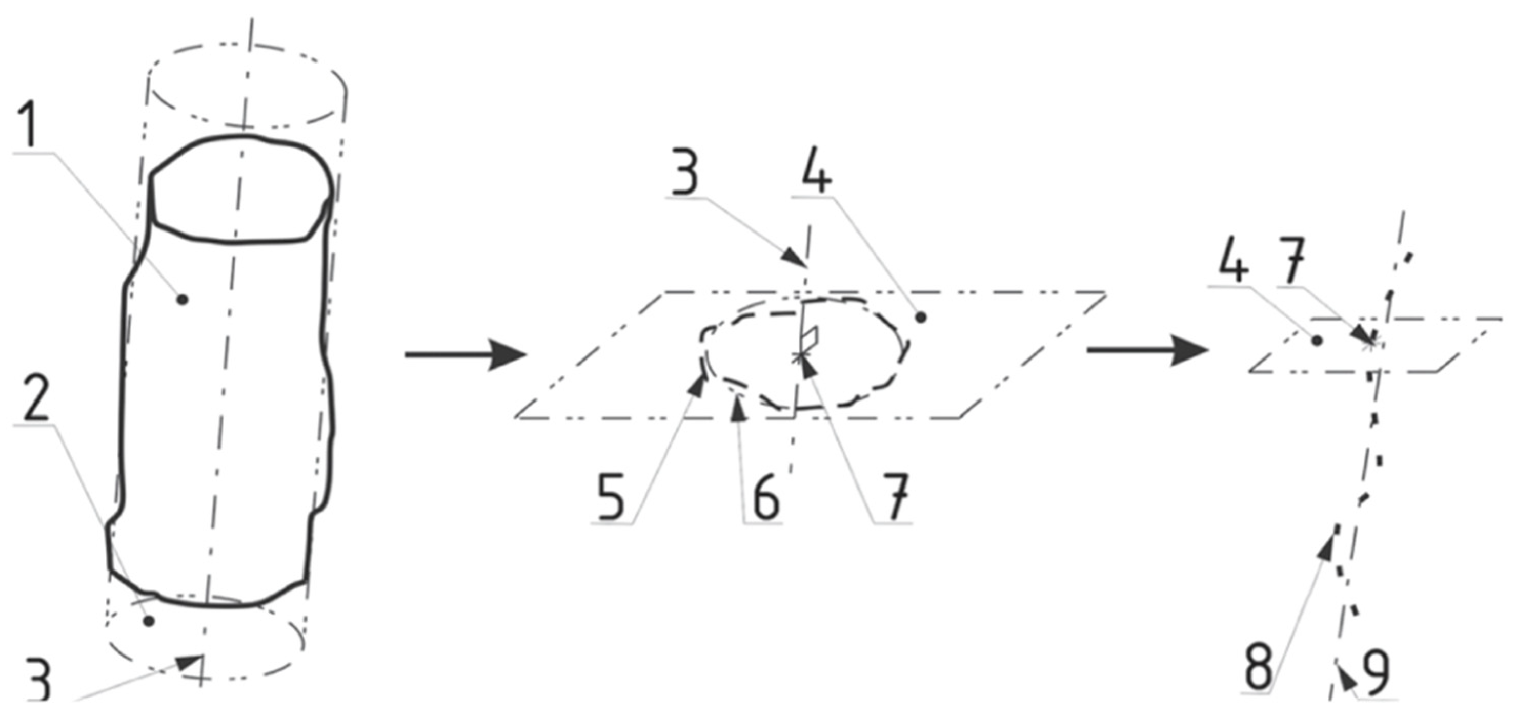
Take a real cylinder, represented in
Figure 1 by its “skin model” 1, a non-ideal surface model [
12] including deviations (of form, of orientation or of position).
The axis can be defined as the derived feature, i.e. the extracted derived “real” feature 8 (the set of points representing the centers 7 of the local associated circles 6 to real cross-sections 5) [
14]. It also can be defined as the ideal straight line 9 associated to it; or as the axis 3 of the associated (ideal) integral feature of type cylinder 2.
Depending on the (often implicit) choices for the criteria (e.g. least squares or minimax) and for the material constraints (e.g. external or without constraint), the association operation [
15] can end up with more than twenty different meanings, just for a cylinder. When the “axis” is established from larger and / or more complex set of integral features, like a set of two coaxial cylinders, or an elliptical tube, this may be even more misleading.
These notions of axis, association, criteria, or accuracy are frequently not (re)defined in an explicit way. Some others may not even be mentioned, like the datum system or geodetic network with respect to which the device is supposedly aligned. In many occasions, the uncertainty on this definition does not impact the performance, because the actual functional accuracy is less strict than the required one, and can accommodate a larger budget.
2.2. From an axis to a situation feature of type straight line
The case of the cylinder shows the huge variety of ways to define what is its axis. At least in that case is defined a method to univocally define a “real axis”. What if the integral feature is not a cylinder, or, say a cone? Or a cylinder with an elliptical generatrix? Or a wedge? For these three examples, it is easy to define the nominal axis. A cone being a surface of revolution, its axis will be the straight line around which the profile is turning, leaving the surface invariant. An ellipse being defined by its two axes, the axis of the elliptical cylinder will be the straight line parallel to the directrix and passing by the intersection of the two axes of the ellipse, so that any translation along this straight line will leave the surface invariant. As for the wedge, the axis will be nominally defined as the intersection of the two planes constituting the wedge, and along which the wedge can slide leaving its surface invariant.
There is no rule to define the corresponding real axis, and there cannot be one, given the huge variety of possible cases. This is also not determined what would be the usage of such a real axis, regardless of the possibility to define it properly. On the other hand, by considering the three above case, there is a common element : the straight line considered as the “nominal axis” is linked with a property of the surface to be left invariant by a transformation involving this straight line: translation along, or rotation around. This is a mathematical property that is captured by the notion of invariance class, introduced by Clément et al. [
16] and exposed in ISO GPS [
12]. In the previous cases, a cylinder belongs to invariance class cylindrical, a cone to invariance class revolute, a wedge to invariance class prismatic. The invariance classes define corresponding situation features of type straight line. The three complementary invariance classes are the spherical and the planar classes (that do not involve any straight line) and invariance complex (that locks all degrees of freedom and consequently for which the choice of the straight line has no specific meaning: what would be the “axis” of such a surface?)
2.3. ISO GPS Situation Features
The situation features of an integral feature are defined in the ISO GPS system [
12] as ideal features of type point [PT], type straight line [SL] or type plane [PL]. For any integral feature, depending on the invariance class it belongs, the minimum set of situation features (also called MGRS, or Minimum Geometric Reference Set, in [
16]) is made of at most one point, one straight line and one plane. In such a set, a condition applies to ensure mathematical complementarity of the invariance classes: the Point is set to be on the Straight Line, and the Straight Line is set to be contained in the Plane:
This minimum set of situation features is called hereinafter a
ToLiP, “
poinT On Line In Plane”, and can be explicitly represented [
17] (see
Figure 8).
The relationship between an integral (single or compound) feature and its situation feature(s) is defined by intrinsic parameters depending on its nominal shape and invariance class [
12]. For a cylinder, of invariance class cylindrical, the situation feature is a straight line, and the linear situation parameter is unique: the radius, and there is no angular situation parameter. For the neutron guides studied in [
2], hollow tubes of rectangular cross-section, the linear parameters are the width and height of the rectangle, and the center offset; the angular parameters are implicitly all square.
The more complex the feature, the larger the set of intrinsic parameters. For the four poles of the quadrupole magnet, that constitute a compound feature made of a collection of four identical features, and which is of invariance class prismatic. The set of situation features of the collection is therefore made of a plane and a straight line, with the condition that the straight line (along which the collection is free to translate) is contained within a plane (preventing the rotation around the straight line).
On top of the shape parameters defining the intrinsic shape of its pole, the situation parameters of the collection of poles are their distance to the straight line (the radius of the inscribed cylinder), and their angle (45°) between the poles and the plane.
The situation features, as their name indicates, are then used to define the situation (location
and orientation) of their integral feature (here a compound feature). Setting up their own situation gives therefore ways to handle all translational and rotational degrees of kinematical freedom of the integral feature seen as a rigid body, and ultimately to define the situation tolerances along the directions defined by its situation features [
1].
2.4. Definition of a non-geometrical axis (e.g. magnetic axis)
With much more demanding levels of accuracies for upcoming scientific projects (e.g. [
4,
5,
6,
7,
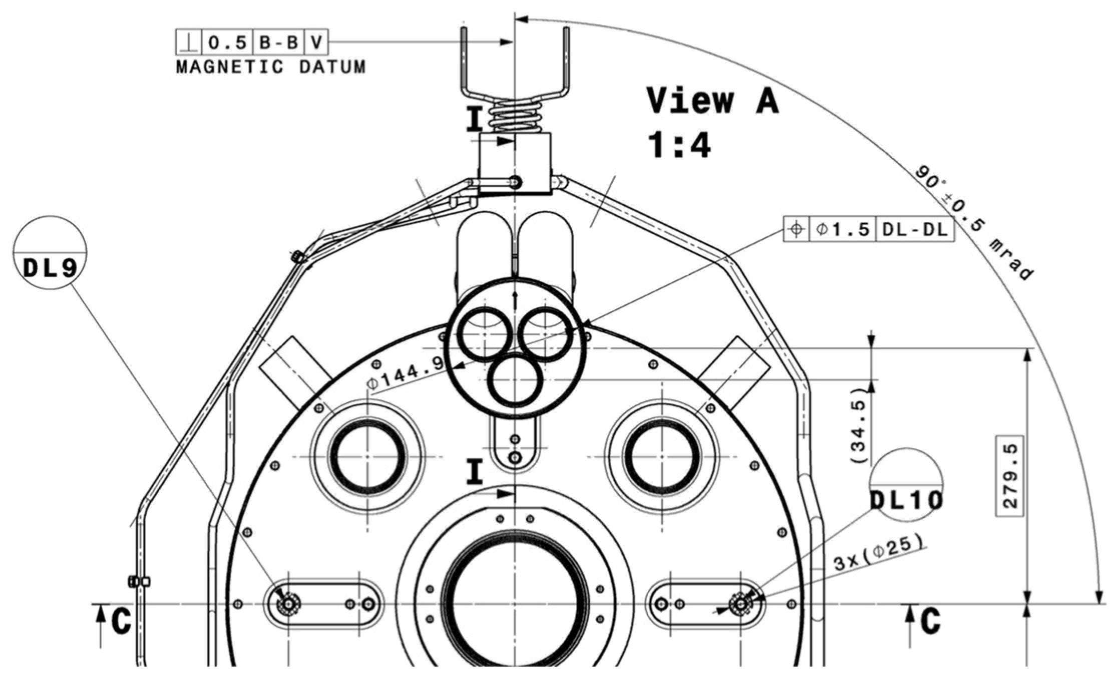
8]), such uncertainties may impact the final result by introducing biases and misunderstandings between stakeholders. In this latter case, the complication comes also from the fact that the axis is not defined from geometrical surfaces, i.e. integral features. Indeed, the components used in such facilities are frequently having functional features that are electromagnetic: we speak of the “magnetic axis” of a magnet, or the magnetic polarization plane of a kicker, or the axis of a resonant RF cavity, without such an axis to be directly linked with the geometrical shape of the poles or conductors that are creating the magnetic field [
18]. Characterizing these axes so that they may be later used as datums is one of the challenges that this paper addresses.
Figure 2.
Example of the drawing of a superconducting magnet, aiming at defining a “magnetic datum”, of type probably Plane, potentially established on magnetic properties of the magnet. The drawing is leaving some uncertainties on both the identification of the specified features, the establishment of datum system, and the characteristics handled by the geometrical specifications.
3. Managing mutual situations
The possibility to manage the mutual situation (location and orientation) of any two features or collection of features is the fundamental motivation of the ISO GPS and ASME GD&T. This mutual situation may be relative (when no one feature has a primary role) or absolute, one of these features defining a datum system or datum reference frame. This is beyond scope of this paper to develop a whole theory of the mutual situation currently under development [
18]. This paper will focus on and be restricted to the mutual situation of only two features or collection of features, and to the case where all degrees of freedom are locked (mutually fixed features).
Mutual situation of ToLiPs
A complete ToLiP (corresponding to a feature or collection of features of invariance class complex) is a triplet, a set made of three situation features of each type, with a “tolipian” condition that gives the ToLiP its name: poin
T on
Line
in
Plane. Partial ToLiPs made of one single or of only two situation features define other invariance classes where not all degrees of freedom are locked [
12,
16]. Handling the situation of a device along its lifecycle means managing the mutual situation of the minimal set of its situation features (ToLiP) with respect to either the ToLiPs of other functional features of the device (internal use) or an external datum system, itself defined as a ToLiP (set of situation features of the resulting datum system [
9,
19]).
In order to manage in a systematic way this mutual situation between two ToLiPs, we have introduced a new concept, called
CoToLiP (prefix
Co standing for “
composition of ToLiPs”) [
2]. A CoToLiP is made of a ToLiP and of a set of three linear and three angular parameters.
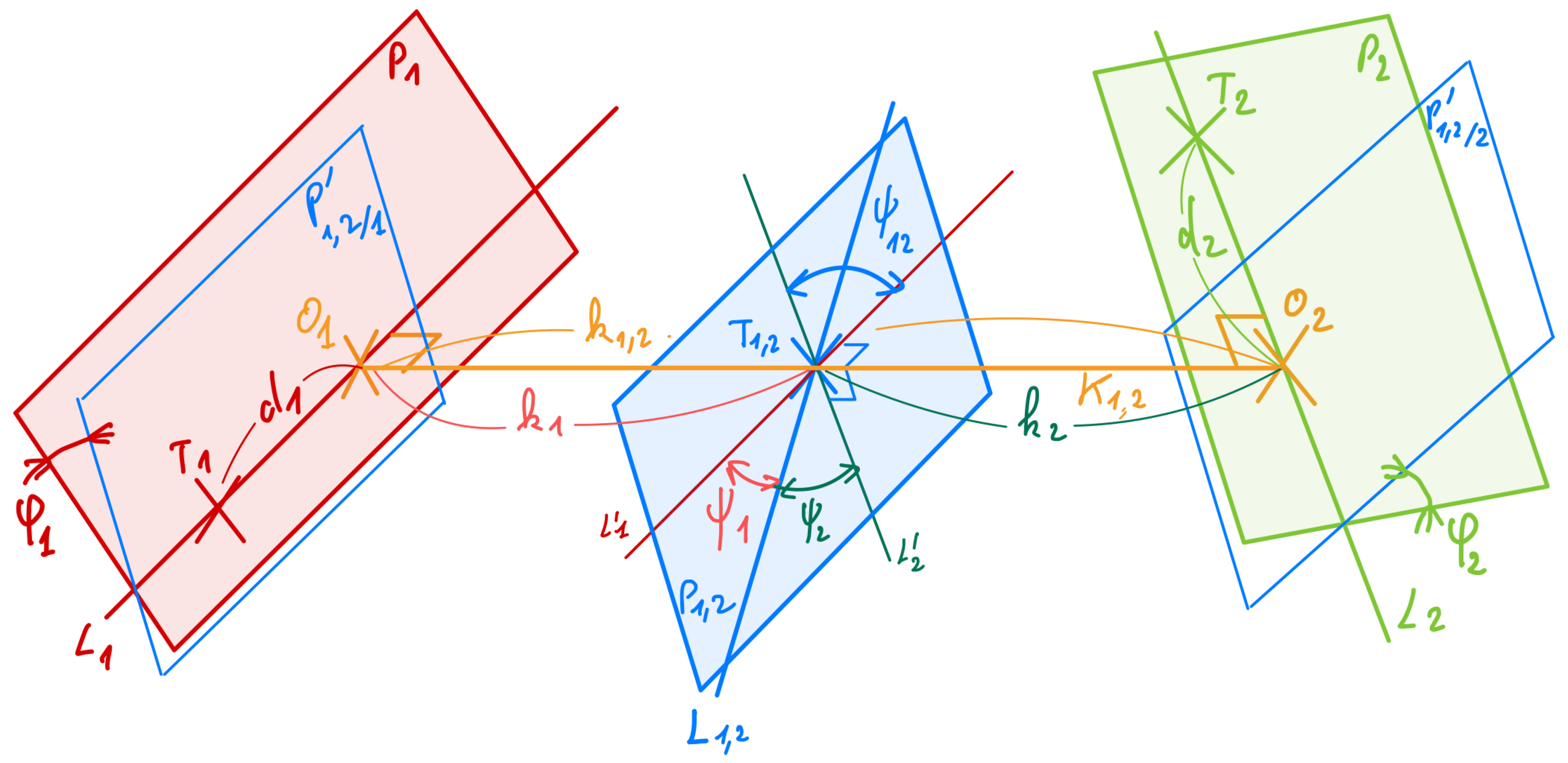
The
CoToLiP represented in
Figure 3 (in blue) is the composition of two triplets (in red and in green) of situation features of type complete
ToLiP, each of them made of a point
, a straight line
and a plane
and with the “tolipian” condition:
The CoToLiP is defined as follows, in order to be commutative:
is the straight line which is the common perpendicular to and ;
is the point in the middle of the segment ;
is the plane perpendicular to the straight line containing ;
are the orthogonal projections of on ;
is the bisecting line of and ;
are the two planes after translation along of and containing .
The six parameters of mutual situation (mutual location
; mutual orientation
) are directly derived [
18]:
along ;
along ;
around ;
around .
The CoToLiP is a commutative operator. Its input features are two ToLiPs,
; the output feature is made of the ToLiP
, and the set of six parameters of mutual situation.
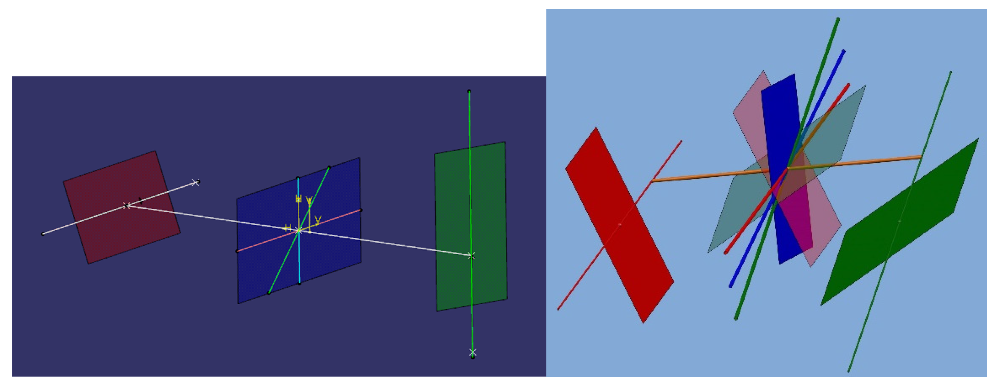
Figure 4 represents a representation of the CoToLiP in a CAD environment. Future work will develop a calculation tool based on solid mathematical concepts.
This CoToLiP tool was used in an industrial case: the handling of the situation of the components of an particle accelerator. The CoToLiP was introduced in order to fill the gap between the world of component makers, with specifications expressed with ISO GPS or equivalent tools) and the world of integration, installation, survey and alignment, based on coordinate measurements and establishment of coordinate systems. More generally, if the link between the two worlds of specification and of verification is existing and is daily used, it is not seamless and induces many understandings and sometimes impossible or very difficult translations, sometimes requiring interface actors able to speak both languages [
20]. The idea of the present work stems out of this observation: the need for an intermediate object, for an interface tool. This object is the ToLiP.
The notion of situation feature (point, straight line, plane) is defined (somehow implicitly) in both worlds, and there is the possibility on the one hand to explicit and group the situation features to constitute a ToLiP, and on the other hand to establish a coordinate system on any ToLiP. Hence the bridge: handling ToLiPs in the geometrical specifications world rather than simply planes, straight line and points extends and clarifies many cases; and handling ToLiPs in the verification world is just equipping coordinate systems with additional meaning, transforming them into real skeletons. The present work is part of a wider effort to make this bridge consistent, powerful, operational (offering calculation tools) and standardized.
4. Typical components of a Big Science beam-based facility
4.1. Components of an accelerator, and steps along their lifecycle
The European Spallation Source (ESS) project [
21] aims at running a bright powerful neutron source for imagery. A proton beam is given power by a linear accelerator (Linac) and thrown on a rotating tungsten target, triggering spallation reaction that produces neutron beams that are extracted and sent to experiments.
The first phase of the lifecycle of such beam-based big science facilities is to set up its optical layout according to the scientific aim and the nature of the beam. This leads to defining the theoretical (nominal) situation of all devices according to their type, allocated to a functional slot along a lattice [
22].
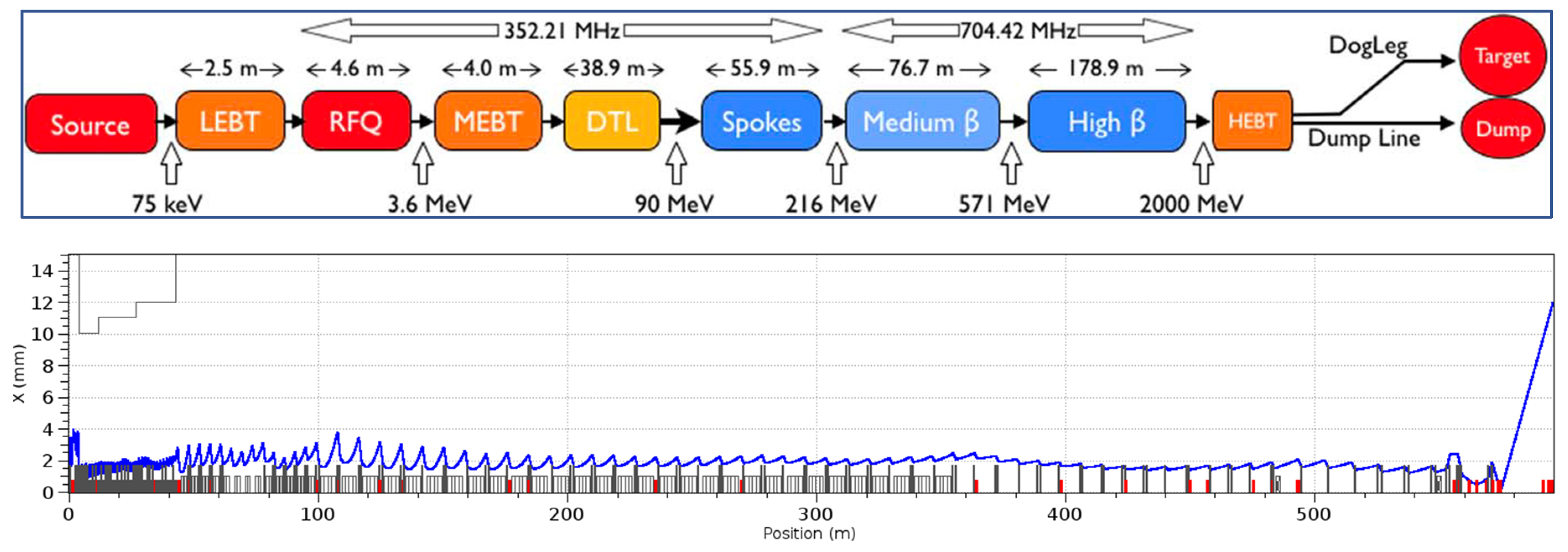
Figure 5 shows on top a schematic view of ESS Linac, from ion source (on the left) to ejection to the target (on the right) with various accelerating and guiding components all along the way of the proton beam. The bottom part of the figure illustrates the so-called corresponding beam dynamic, which is the ultimate functional goal.
Then comes the phase of design and engineering of every device type as they appear along the beam, so that it delivers the expected optical function.
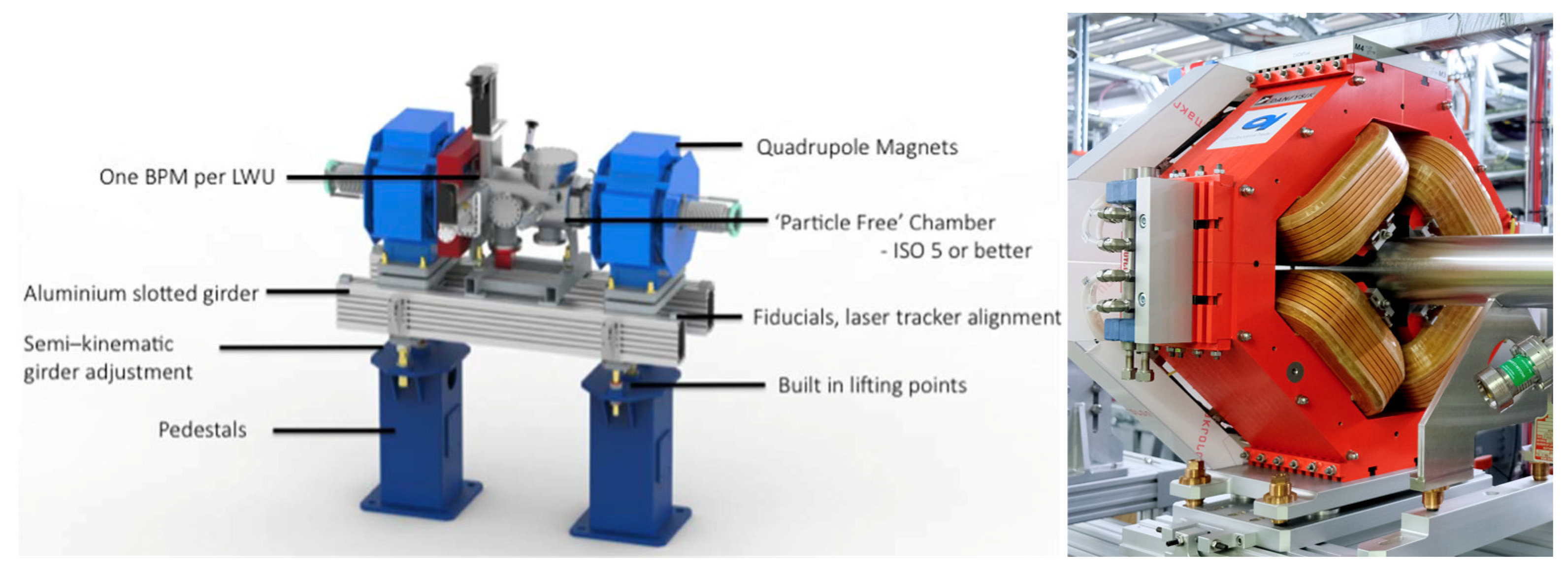
Figure 3 shows the example of a model of a LWU: Linac (Linear Accelerator) Warm Unit, made of two focusing/defocusing quadrupole magnets QH (H for Horizontal) and QV (V for Vertical), the vacuum chamber inside which the beam is circulating, as well as the BPM (Beam Positioning Monitor) and a COR corrector magnet, close to an accelerator cavity CAVM.
The corresponding conceptual design is shown in
Figure 5 and
Figure 6. This design stage usually includes integration and interface management.
Figure 7 shows an ESS quadrupole magnet with the vacuum chamber integrated inside between the poles, the electrical connections, the supporting girder and the kinematic adjustment devices.
After the manufacturing phase of a given asset (serialized instance of a type), its characteristics are measured and situated with respect to external marks (fiducialization phase). After the asset is assigned to a determined functional slot, installation of a specific device finally occurs. The “alignment of the axis with a ± 50 µm accuracy” is then carried out, using these fiducial marks as targets.
4.2. Situation Features of Quadrupole Magnets
The present study aims to identify and handle the functional features of the devices such facilities are made of. The case of neutron guides, where functional features (mirrors) are of geometrical nature, was studied previously [
2]. The focusing / defocusing quadrupole magnet chosen for the case study of this paper was also studied from another perspective in [
24]. It is made up of four poles, whose intrinsic shape defined by modelling and the result of electromagnetic simulations. The four poles may be considered as the geometrical functional features of mechanical type.
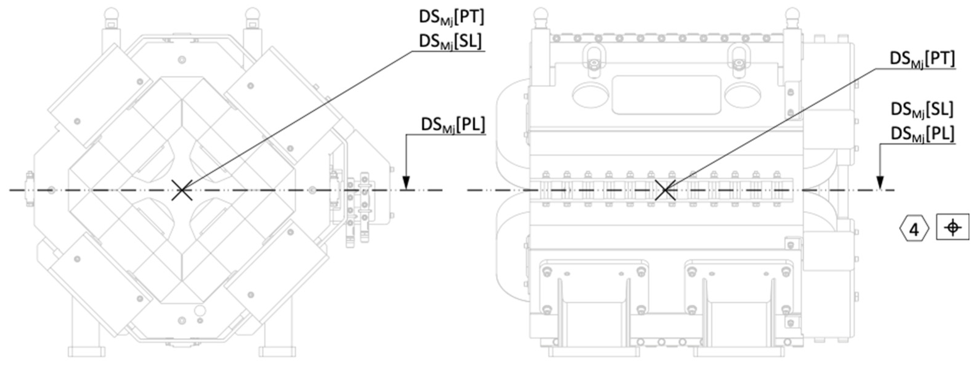
Let us consider, to start with an easier assumption, that the axis of the quadrupole magnet is nominally defined as the intersection of the mid-plane of each of the four poles. The orientation of the magnet is then defined with the “polarizing” horizontal plane. The front and back faces would serve to define the longitudinal center along the beam. These three nominally defined features, the axis (a straight line), the center (a point) and the polarizing plane (a plane), are the so-called “situation features” of the magnet. They are here explicitly indicated on the drawing
1 shown in
Figure 9.
These situation features may be either mechanical or magnetic and are nominally coincident. The first ones are important for magnet design as well as for spatial integration, whereas the latter are those representing the function of the magnet: this is its “raison d’être”, influence the trajectory beam of charged particles (protons for ESS Linac or LHC collider, electrons in light sources) by submitting them to a magnetic field of a certain shape.
During the installation of the magnet in the tunnel, the poles are not accessible for any measurement, hence the need to measure their situation with respect to the fiducial marks before installation. This is the fiducialization operation: on top of the magnet, the fiducial marks are conical surfaces on which retroreflective targets mounted on a sphere (visible on top of the magnet in
Figure 8) are set up for surveying operations using a laser tracker. The position of these spheres will then be used during installation phase to represent the actual situation of the magnet.
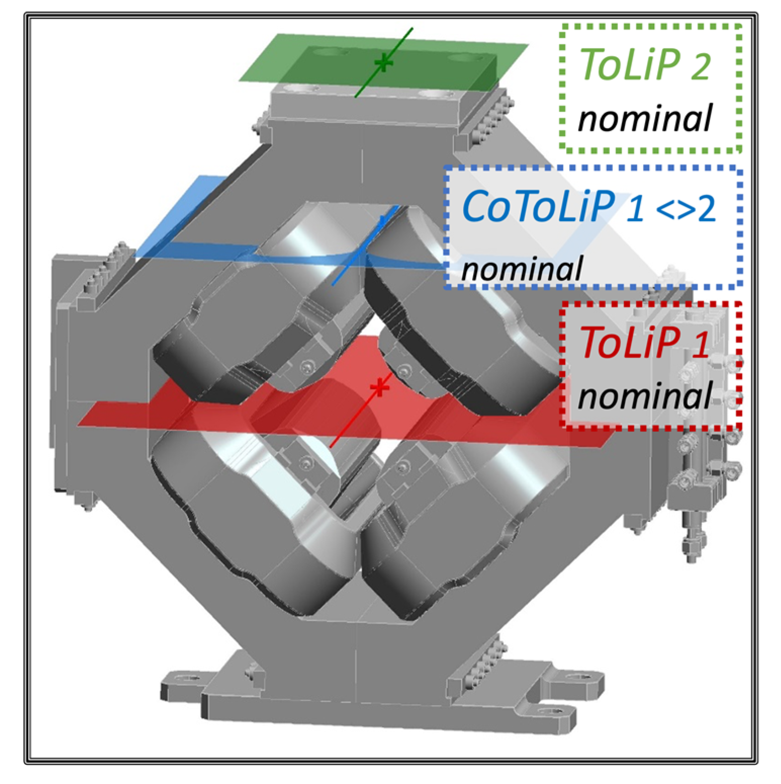
Figure 10 shows the nominal ToLiP of the magnet (ToLiP1 nominal, in red) and the nominal ToLiP of the constellation of fiducial marks (ToLiP2 nominal, in green), as well as the ToLiP representing their nominal situation (CoToLiP 1< >2 nominal, in blue).
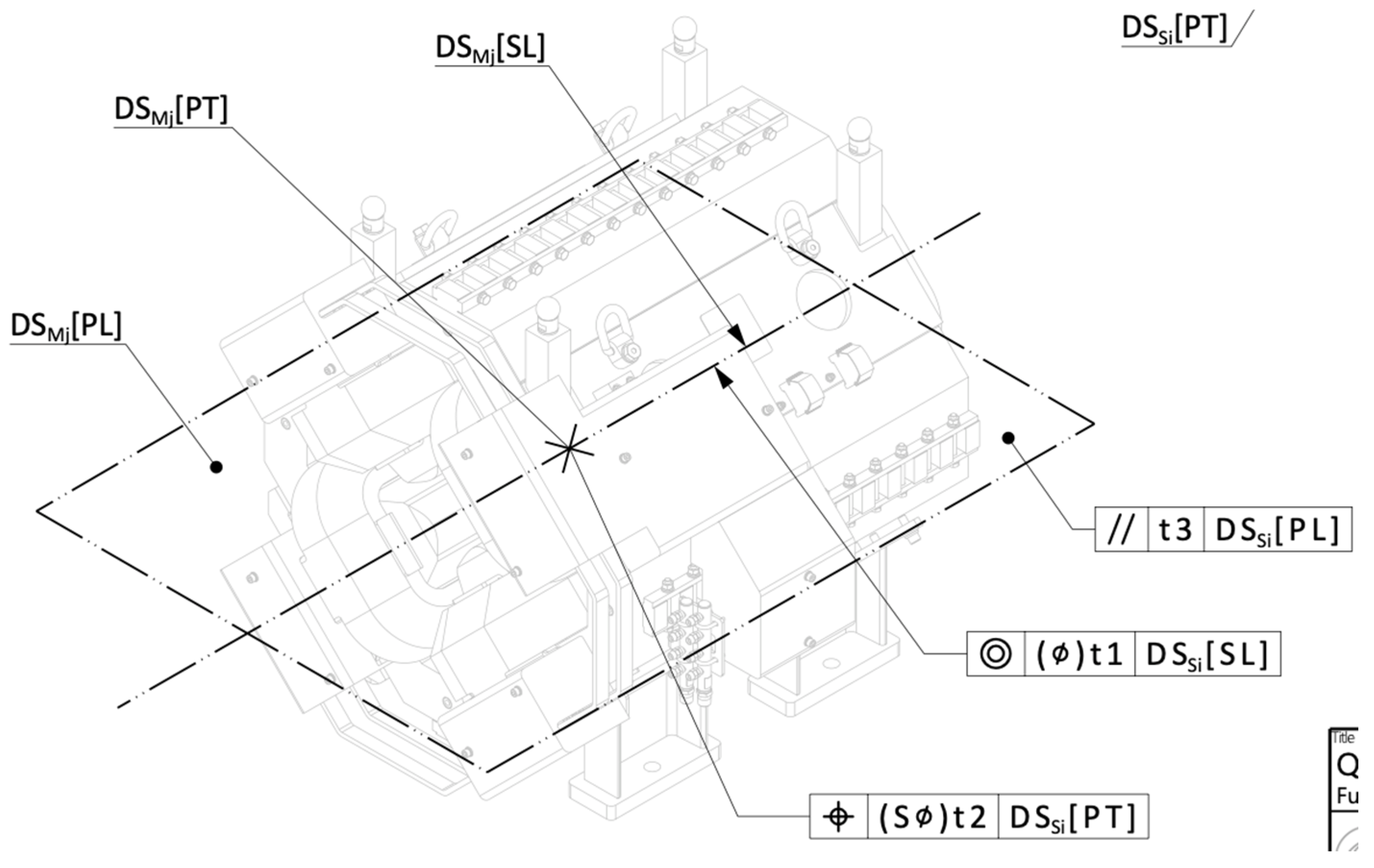
Figure 8.
Excerpt of the generic drawing of a quadrupole magnet (
Appendix A). This drawing explicitly represents and indicates the nominal situation features of the datum system DS of a magnet of type M. The index
j is utilized to identify the serialized magnets.
Figure 8.
Excerpt of the generic drawing of a quadrupole magnet (
Appendix A). This drawing explicitly represents and indicates the nominal situation features of the datum system DS of a magnet of type M. The index
j is utilized to identify the serialized magnets.
Figure 9.
Detailed design of the magnet, identifying the nominal set of situation features of the magnet (ToLiP1, in red; nominal magnetic and nominal mechanical are coincident), the set of situation features of the constellation of four fiducial marks (ToLiP2, in green) and the set of situation features and parameters representing their mutual situation (CoToLiP 1< >2), in blue. The color code is compliant with the definition of the CoToLiP represented in
Figure 3.
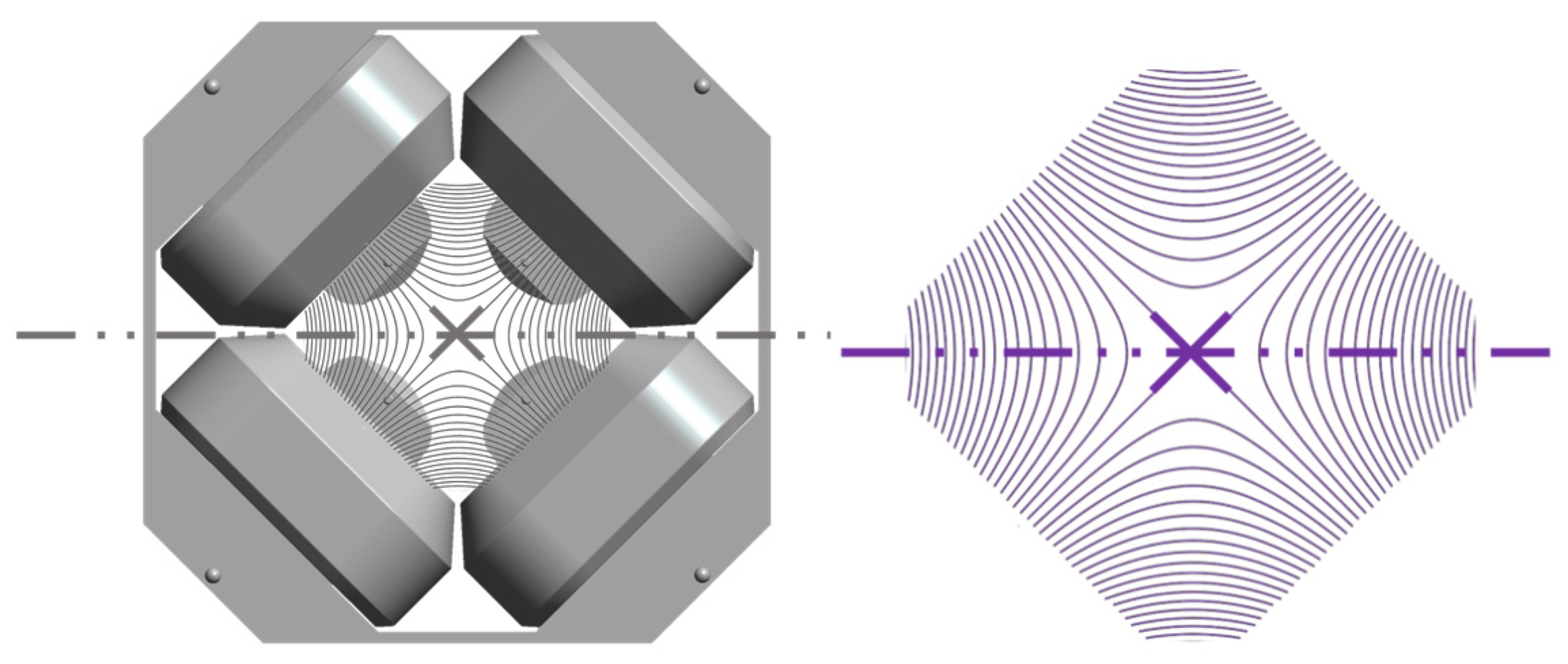
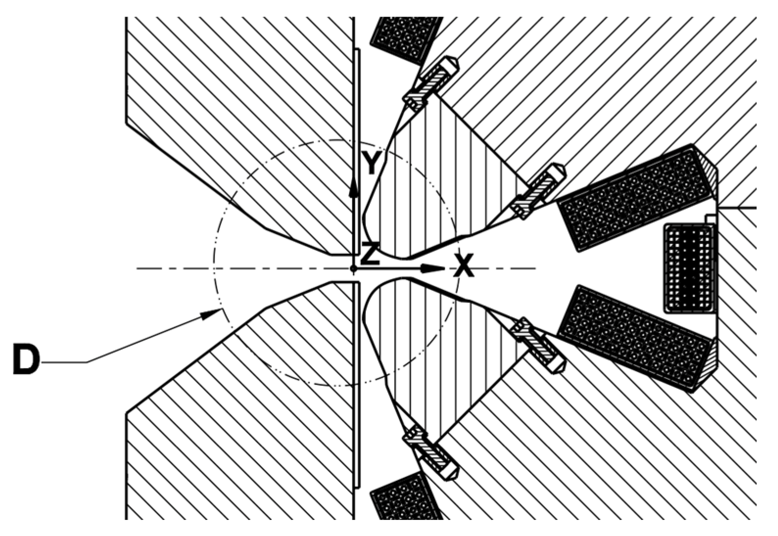
Figure 10.
Situation features of a magnet. Left: the poles of an ESS quadrupole magnet, the nominal mechanical situation features of the collection of functional features (poles, chamfers and faces). Right. End view of the theoretical magnetic field map produced by the magnet poles collectively, and corresponding magnetic situation features. Nominally, the mechanical and magnetic situation features are coincident.
The two next subsections explain how these two nominal ToLiPs are defined.
4.3. Establishment of the magnetic situation features (ToLiP1 nominal)
The magnetic fiducialization is the operation consisting in simultaneously measuring on a magnetic bench the mutual situation between the magnetic field and the spheres put inside the fiducial marks.
Nominally, for this type of ESS quadrupole magnets, geometrical and magnetic situation features are identical, and their ideal situation is defined by the layout of the overall accelerator (the architecture). The challenge consists of ensuring that the reality reaches this ideal aim as close as possible. The sources of deviations are numerous, from uncertainties in design, manufacturing tolerances, fiducialization and operation fluctuations, to alignment accuracy, or quality of the geodetic network with respect to which these measurements are carried out. Making a clear distinction of the various features at stake is a must.
For other types of magnets, there might be no direct correspondence between the geometrical and the magnetic situation features. This is for instance the case for the one shown in
Figure 9, a particular dipole developed for the ALS-U (upgrade of the Advanced Light Source at the Lawrence Berkeley National Laboratory, in California), that couples bending and focusing magnetic properties. This is even more important in those cases to explicitly represent the situation features (in the
Figure 9, they are only implicitly defined by establishing a coordinate system on them), and to ensure a magnetic fiducialization of adequate accuracy in order to determine their situation with respect to the fiducial marks.
Figure 11.
LBNL ALS-U dipole magnet of type Bend-C for Storage Ring, with indirect (through the coordinate system) and not complete indication of the situation features.
Figure 11.
LBNL ALS-U dipole magnet of type Bend-C for Storage Ring, with indirect (through the coordinate system) and not complete indication of the situation features.
This indication does not make it explicit which are the situation features, and hence is preventing the designer from using them in order to establish geometrical specifications and defining the condition on the corresponding characteristics. This is one of the main advantages of explicit and systematic use of the situation features, for the datum systems as well as for the specified features.
4.4. Fiducialization marks using ISO GPS contacting features (ToLiP2 nominal)
Typically, survey targets are spheres located in conical cups, called fiducial marks. Three of those cups are enough to define the six (rigid body) parameters of situation (location and orientation) of the device they are attached on. Defining the location of the center of each sphere of the collection will therefore ultimately define the situation of the whole device.
Using more than three spheres is nominally useless; but in practice it reduces the global uncertainty by improving the spread of the spheres over the extent of the device, and by ensuring some redundancy. Note that the GPS specification coding is identical as soon for any constellation of n spheres, n ≥ 3.
How to indicate on the drawing that the position of these spheres are requested to be measured (for fiducialization phase as well as for the installation phase)? We introduce here the possibility to use contacting features as specified features. ISO 5459:2011 [
16] defines how to use contacting features as the “associated features to the
datum features”. ISO 1101:2017 [
24] does not (yet) define how to use contacting features as the associated features to the
toleranced features. It is proposed to proceed by analogy with similar cases defined in section 8.2.2.2 of ISO 1101:2017, that defines “Associated toleranced feature specification element”: “
By default, the specification applies to the indicated extracted integral or derived feature itself. The associated toleranced feature specification element is an optional specification element. It shall be used to indicate that the specification does not apply to the indicated feature itself, but to a feature associated with it.”
So far, the available “associated toleranced feature specification elements” are Ⓒ, Ⓖ, Ⓝ, Ⓣ and Ⓧ. Such elements are indicated in the second box of the toleranced frame (see
Figure 13 of ISO 1101:2017). Our proposal to introduce an additional associated toleranced feature specification element of type
Contacting Feature2. In our case, the contacting feature is a sphere of fixed size 1.5 inches, whose situation feature is the center of the sphere itself. To indicate the use of this association tolerance feature element, a new modifier CF in a rounded box, is introduced, as shown in
Figure 12. Newly defined indication that the toleranced feature is the associated contacting feature, a sphere of fixed size, a spherical diameter of 1.5 inches (Taylor-Hobson mounting sphere). Excerpt of the drawing specifying fiducialization operation (see
Appendix B).n
3. Since the present proposal is not yet standardized, using this modifier required an additional nota that was added near the title block. “
(CF) indicates that the toleranced feature is the associated contacting feature.”
The ToLiP2 nominal, as represented in
Figure 9 is the set of situation features corresponding to four spheres. It is a complete ToLiP whose explicit definition is the following: the situation feature Plane is the plane containing the four nominal spheres; the situation feature Straight Line is the line in the plane that is in the middle of the spheres and parallel to the magnet axis; and the point is the center of the rectangle made up by the four spheres.
The default determination of the ToLiP of the collection of four spheres extends beyond the scope of this paper, as it requests a generalization of the CoToLiP tool, the MuToLiP tool (under development), that allows to combine more than two ToLiPs.
4.5. Nominal mutual situation of magnetic and fiducial marks (CoToLiP 1< >2 nominal)
The determination of the CoToLiP 1< >2 as
directly yields from the definition in
Figure 3. The two ToLiPs have parallel planes, shifted by a nominal value
H a direction perpendicular to the planes. The CoToLiP is therefore a ToLiP whose plane is the mid-plane of the the two planes of ToLiP1 and ToLiP2, its point is in the middle of the two points, and its line is parallel to the two lines passing through the point. It is represented in blue
Figure 9. The six mutual situation parameters are: (0, 0,
H) for the linear distances; (0, 0, 0) for the angular distances (the two ToLiPs are translated one with respect to the other in the direction perpendicular to the plane by the value
H, without rotation).
The CoToLiP, a ToLiP with its parameters, represents the mutual situation of the collection made of the magnet situation features and the spheres. Knowing where is one ToLiP and the definition of the CoToLiP determines the knowledge of the other ToLiP. This interface role will be used twice. During fiducialization, to determine the real CoToLiP by expressing the deviation of the position of the spheres on the real magnet with respect to their nominal position with respect to the situation features of the magnet. And during installation, this real CoToLiP will be used in order to put in situation the real magnetic situation features (not measurable at the time of installation) by determining the target position of the spheres. These two operations are detailed in the next section.
5. Overall process of fiducialization and installation
The overall process of fiducialization and installation is represented in
Figure 13. The aim is to follow the large yellow double terminated arrow. As an input, the definition of the functional architecture of the slots, and as an output a collection of real components of a given type installed in each of the functional slot to which they are allocated, taking into account their deviation to nominal.
The present paper focuses on the operations of layout definition, fiducialization and installation phases. The other phases fall beyond the scope of this paper, but the formalism and concepts used here (mutual situation of ToLiPs) can be and are effectively applied to the phases of design, spatial integration and manufacturing in a similar way.
5.1. Functional layout or architecture
The functional layout of the accelerator, and more generally the overall architecture of any complex assembly, is set by defining the situation of the functional slots corresponding to each equipment to be installed in the overall system
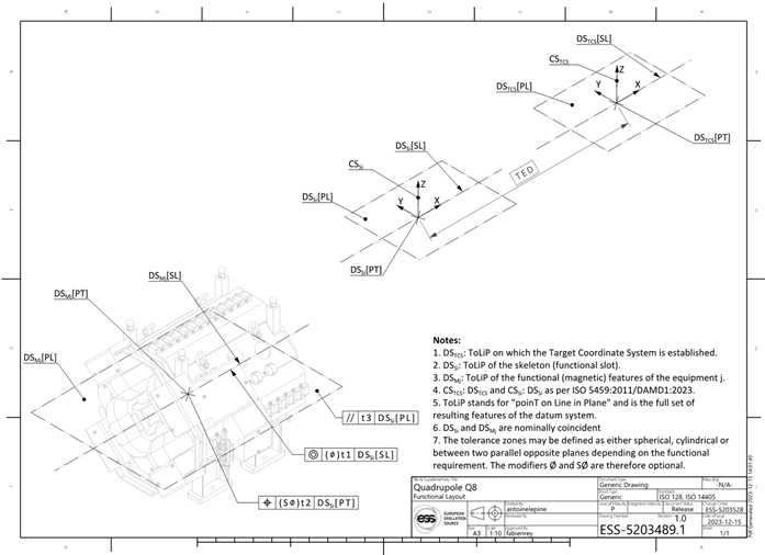
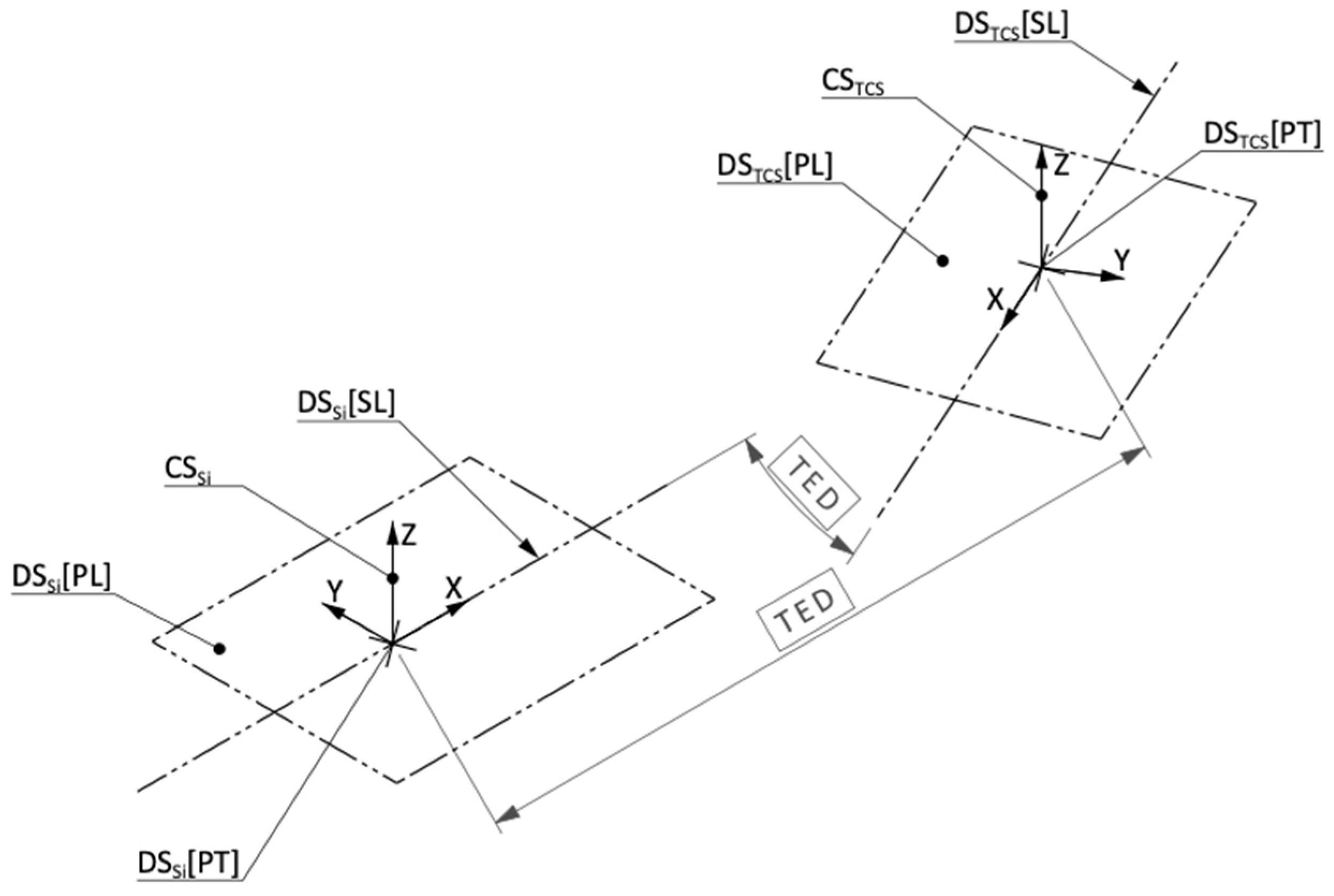
Figure 14. Situation of the functional slot
i (indicated
Si) with respect to the global ToLiP on which the main coordinate system TCS (Target Coordinate System) is established. In the present case, the situation is exemplified by using only two TEDs (Theoretical Exact Dimensions): an angular TED defining a rotation around the
z axis perpendicular to DS
TCS[PL] passing by the origin DS
TCS[PT] of the TCS; and then a linear TED defining a translation along the
x axis DS
Si[SL] of the functional slot. In general, all six parameters of mutual situation can be individually addressed. Excerpt of the drawing defining functional layout (see
Appendix A).shows the example of how this situation is defined at ESS. , and give the whole set of generic drawings defined at ESS. This functional slot defines the nominal situation (location and orientation) of the situation features of the item associated to any equipment. Since all mutual situation parameters are fully locked (no mobility), this item can be represented by a complete ToLiP.
The tolerance of situation (location and orientation) of the situation features of the item in a functional slot can now be expressed using an extension of the ISO GPS symbology: the specified features are the three situation features of the ToLiP of the item, as defined in
Figure 10 for instance. This is a new possibility that we introduce here, offering to the designer the tool to express explicitly the design intent and catch the functional requirements. The corresponding geometrical specification is defined using the usual geometrical specification ISO GPS tools [
24], as exemplified in
Figure 14.
This new tool to specify the location or the orientation of a situation feature is not yet standardized in ISO GPS. It comes with some restrictions of use, that need to be properly addressed: since the situation features are ideal features, according to one of the very ancient postulates of Euclid
4, according to his fifth principle, the line is extended potentially as far as needed, which would jeopardize any possibility to put a condition on the corresponding characteristic of coaxiality between DSMj[SL] and DSSi[SL]. A restriction in length must be imposed, that is functionally representative. By default, this length is the overall dimension of the corresponding item along the same direction. It may be extended by appropriate indication to consider for instance, the “magnetic length”, capturing the functional behavior of a magnet to bear its influence beyond its mechanical borders. Analog types of restrictions apply on the specified situation feature of type plane.
5.2. Fiducialization on magnetic bench measurement
The scope of this paper is to focus on the installation of real devices (e.g. a serialized magnet) in real functional slots (e.g. the slot Q8) in the accelerator. We will now assume that, according to the design, a magnet was manufactured, and focus on the way to determine the situation of the magnetic situation features with respect to the fiducial marks.
The real mechanical functional features are measured in a CMM (Coordinate Measurement Machine), and the corresponding situation features are obtained through an association operation [
15] in an identical way as for the neutron guides [
2], with a gaussian (least mean squares) criterion and without constraint with respect to material. These association parameters can be defined in the functional (FUN) specification [
13]. They would in this case be indicated with a [GM] modifier in the datum section of the specification frame [
25].
The real magnetic functional features are, on the other hand, not directly measurable with a CMM. They are measured on a magnetic bench, whose location and orientation is captured either with a laser tracker or a CMM together with the position of the fiducial marks. Measurement technics may vary depending on the magnetic characteristics and sought accuracy. Whatever the method, the principle remains the same: capture in the same geometrical framework the mutual situation between the real magnetic field and the fiducial marks. The present paper introduces the CoToLiP tool in order to provide with a consistent and homogenous common way to handle this mutual situation.
The real magnet is installed on a magnetic bench using a magnetic coil field sensor as described typically in [
26], and the situation of its set of magnetic situation features is determined with respect to the alignment measurement mean.
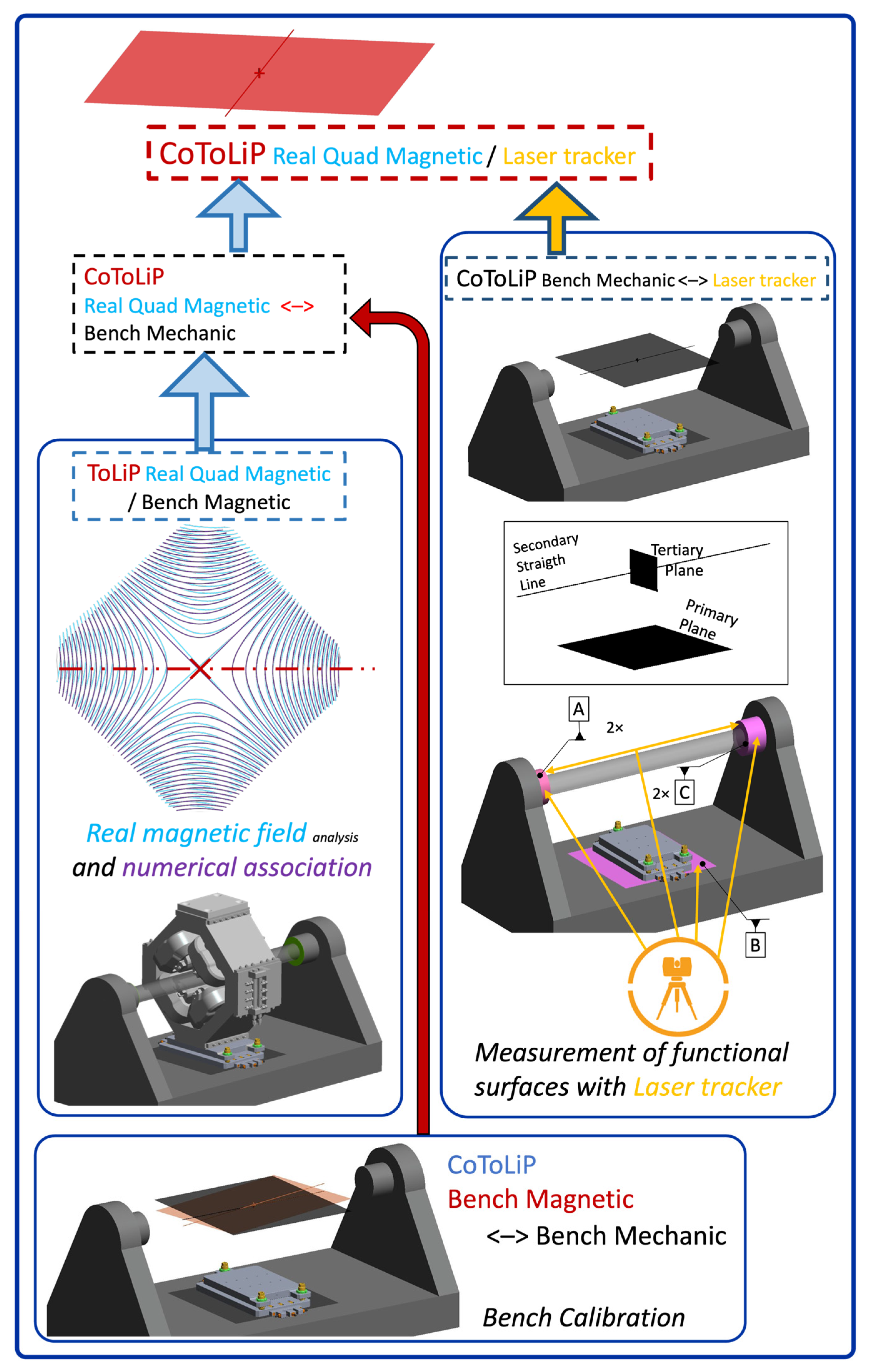
Figure 16 details the example of the fiducialization of an ESS quadrupole with a laser tracker. The magnetic set of situation features (ToLiP Real Quad magnetic) of the magnet is obtained through an association operation between the real and the ideal magnetic field, as obtained either from calculation or from simulation. Here they are by default with a gaussian (least mean squares) association.
We here introduce is an extension of the operation of geometrical association as defined in [
13], applied in the case of the magnet to its non-geometrical (magnetic) functional features. This is a very useful extension to be able to establish ISO GPS situation features even in the case where the functional features are non-geometrical, like here magnetic field. It could also be an electrical field (for electrostatic bumper) or varying electromagnetic field (for radiofrequency cavities) or even an acoustic field (for room acoustics) or thermal field (for additive manufacturing machines). The only requirement is to adapt the optimization function according to the considered ideal field.
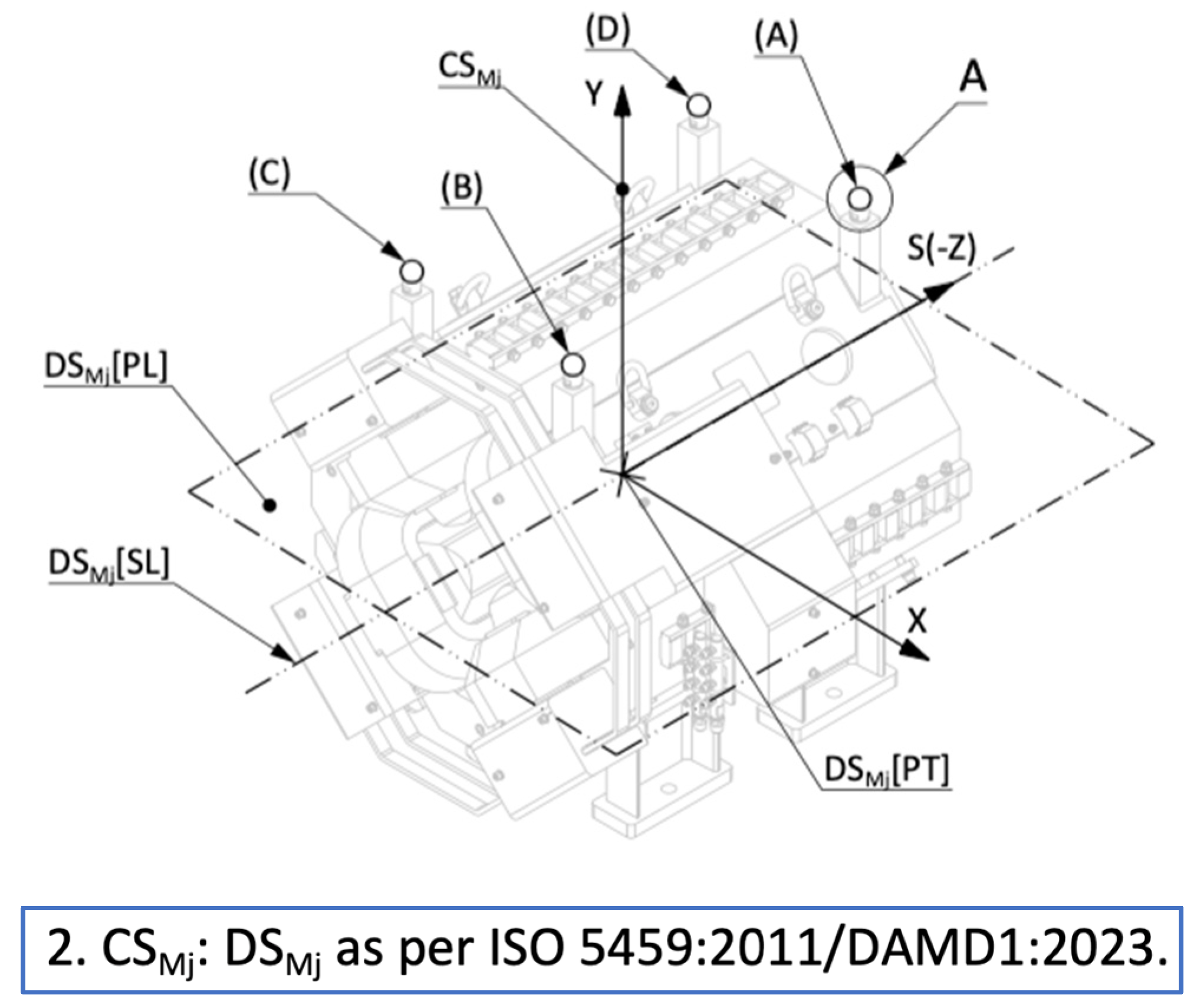
The second part of the fiducialization process is to determine the situation of these real magnetic situation features with respect to the real fiducialization marks. Once established, the magnetic situation features are used to build up a local “datum coordinate system” (indication CSMj:DSMj derived from [
25], defined in drawing Note 2, see
Figure 17).
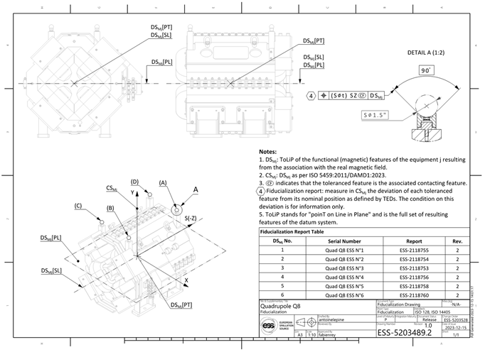
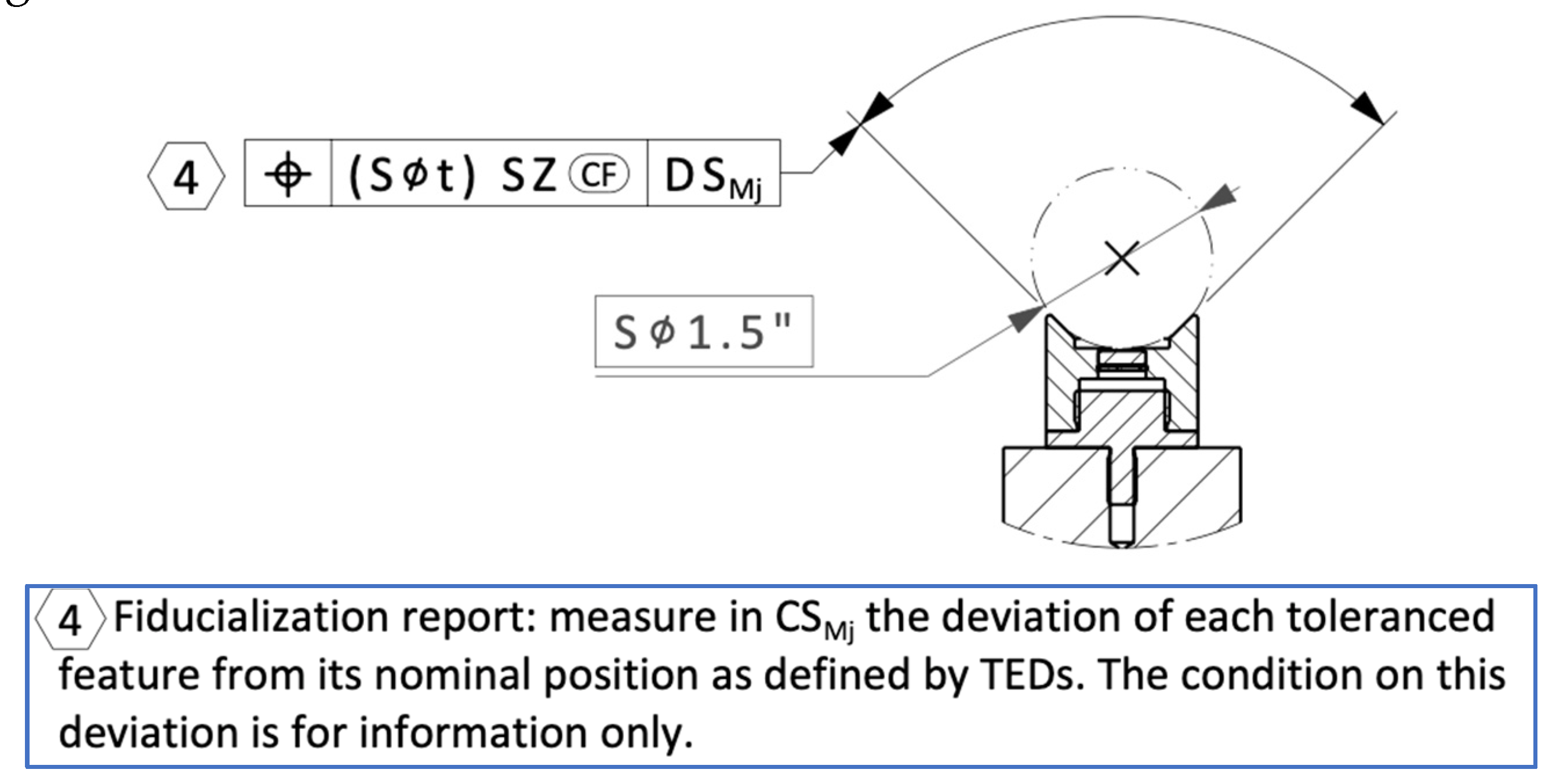
The fiducialization is carried out by measuring the position of the fiducial marks, through their associated contacting features, the reflecting mounting spheres. Their real position is measured in CSMj and recorded. The instruction is given in the 2
nd drawing (see
Appendix A) by the indication reported in
Figure 18:
The instruction requires a Nota, because there is no ISO GPS tool that allow to only get the measure characteristic without putting it under condition
5.
This phase of the process is modelled in
Figure 19. The contacting features (the spheres) are inserted in the real fiducial marks, the cups indicated in light blue. The position of these four spheres is then measured individually (induced by the SZ modifier) by the same laser tracker in the same posting as for the first phase of the process. The output of this process is the establishment of the “ToLiP2 measured” of the collection of four points (not necessarily coplanar, because the fiducial marks are real). This ToLiP is indirectly allowed to deviate from its nominal situation within range of about the
t value.
The third and last phase of the fiducialization process is to build up the real CoToLiP. The two input features are respectively the ToLiP2 established on the real spheres, and the ToLiP1 established from the magnetic bench. The result, following the definition of the CoToLiP operator, is shown in
Figure 20.
This measured CoToLiP represents the real measured mutual situation between the magnetic situation features and the position of the fiducial marks. It may deviate from the nominal CoToLiP, and it captures the defaults of manufacturing at the level of the functional features: their actual effect on the magnetic field.
5.3. Specification of installation
This final phase was the one motivating the whole improvement: on the field the survey and alignment operators did not always get clear instructions on how to deal with the fiducialization reports. And this was in large part due to the fact that there was no clear definition of the mutual situation with the spheres and the functional features. Thus, determining the target position of the spheres was appearing somewhat like an adventure, with lengthy discussions between the owners of the components, the installation coordinators on the field and the survey operators, each of them having a diverging opinion.
The way out was to start by considering an installation operation as an assembly phase! After all, do not we call the accelerator “the machine”? In a large (somehow very large – some hectometers long) system, the “machine frame” is the tunnel, in which are assembled all the other components. Hence the idea to describe the installation instruction in the form of an ISO GPS drawing, as for any assembly drawing.
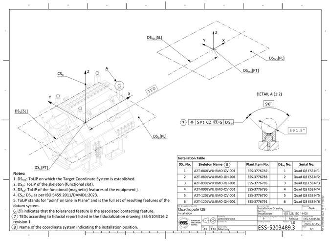
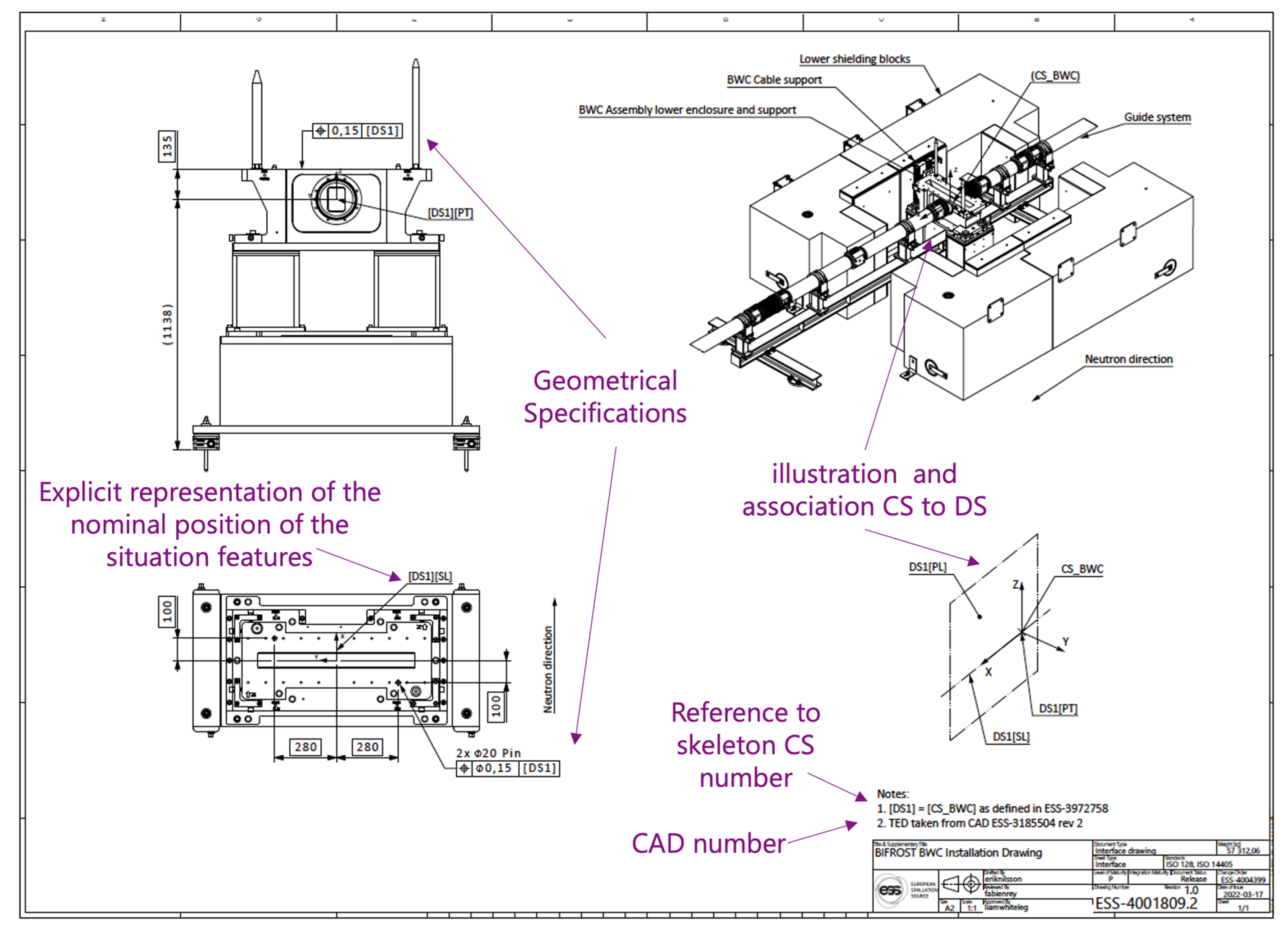
An example of such an installation “assembly” drawing, with annotations to explain their use, is provided in
Figure 21. This is a case where the functional features area accessible for direct measurement. If this is not the case, then fiducialization prior to installation is needed.
In the case of the quadrupole magnet, whose situation features are not measurable for installation, the same principle applies, but the instruction of installation is by defining the target position of the spheres in contact with the fiducial marks of the magnet. The corresponding “assembly” installation drawing is shown in
Appendix A, and the ISO GPS-like instruction is detailed in
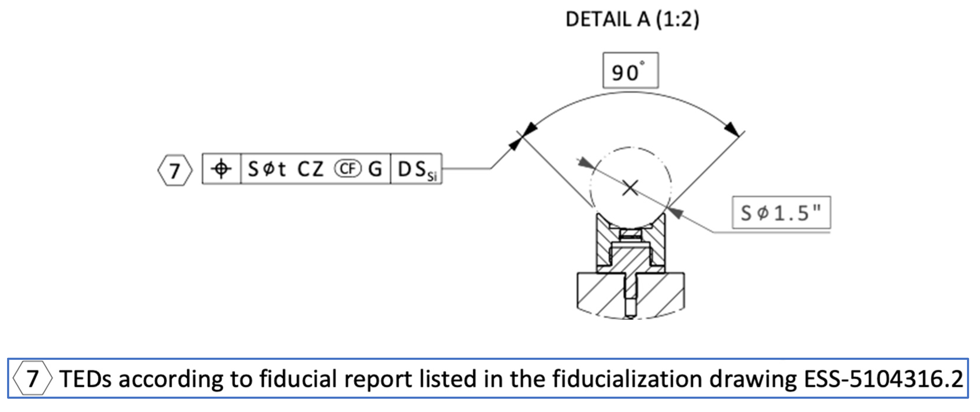
Figure 22.
This indication contains three modifiers. The modifier CZ, not yet standardized, was presented above. The modifier CZ indicates that this is the whole constellation of spheres that must meet the set of TEDs collectively. And the modifier G indicates that the criterion to establish the global position of the spheres is Gaussian (least mean squares). In this way, the operators do not need to care about the CoToLiP, which is a tool used in order to define the TEDs: this is a combination of the fiducial data and of the nominal situation of the functional slot to which the component is allocated.
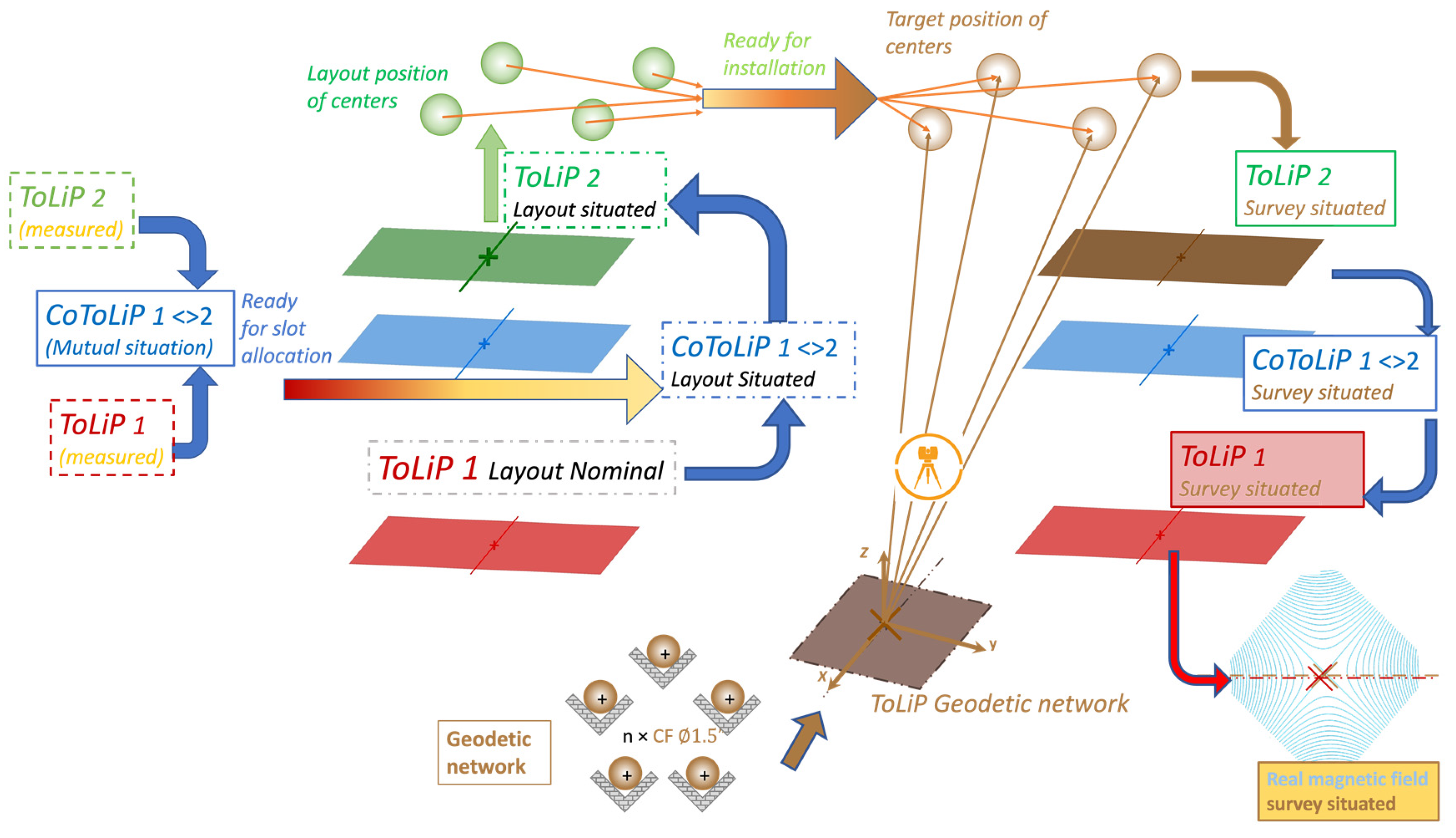
The last two phases of the overall process; slot allocation and installation, are modelled in
Figure 23. This model illustrates the central role of the CoToLiP characterizing the mutual situation between the spheres and the magnetic datums.
In the slot allocation phase, it is used to determine the target value, also called “layout position of centers”: the knowledge of the ToLiP1 layout nominal (functional slot) defines the situation of the CoToLiP “situated, and consequently the knowledge of the ToLiP2, with respect to which the position of the real fiducial marks are defined.
In the installation phase, the ToLiP2 is installed in the right situation by the measurement and optimization of the position of the spheres. The CoToLiP, by inverse transformation, gives the exact situation (modulo the measurement accuracies) of the real functional situation features, even before the magnet is switched on.
In other words, the CoToLiP 1< >2 of real mutual situation, set up by measurement, is used to define the target position of the fiducial marks in the layout, then to fix the situation of the functional features in the geodetic network. It allows to consistently handle in one go the six degrees of freedom.
5.4. Advantages and limits of the global process
The introduction of the CoToLiP was key to improve the situation on the field, and it contributed to a huge clarification in the ESS project by providing a unified tool to express the requirements on clearly defined functional features and to translate them all along the lifecycle. Hours saved, quality improved, interaction between teams enhanced, a huge added value.
The price to pay was to derive the concepts into two series of generic drawings, one of them is shone in
Appendix A. The CoToLiP is not an easy tool, it is therefore operationally used essentially for the phase of slot allocation and determination of the target value for the fiducial marks. The generic drawings are fully based on the CoToLiP, without the need to show it up. And the introduction of the new modifiers are natural extensions of existing ISO GPS tools, and were rather easy to communicate to the teams with appropriate training.
Some limitations so far are the following:
A LWU is made of two quadrupoles. And the adjustment system applies to the whole girder, not to each magnet individually. The functional features of the girder needs to be expressed as the CoToLiP of each magnet. Since a CoToLiP is also a ToLiP, this is not conceptually an issue, but the rules of optimization need to be made explicit. This is a natural extension of the method.
The CoToLiP tool does not yet offer the possibility to calculate the tolerance values to be applied to the situation features. This is a 6D-tolerance stack up, very promising, but challenging because it addresses with high accuracy the influence on the position of the rotation axis.
The CoToLiP applies only to two ToLiPs. What if a girder would bear more than two magnets? How to extend? This is the case of LBNL ALS-U girders, called « rafts »: not only are the magnets more than two, but on top, they are of different kind (sextupoles, quadrupoles, in different magnetic variants), and they are not coaxial, because this is not a linear accelerator, but a circular synchrotron.
The tools (CoCoToLiP, MuToLiP) are under development and, in the case of ALS-U, are expected to be used in the process to define the alignment strategy for the storage ring.
6. Discussion and perspectives for ISO GPS evolution
From the ISO GPS perspective, the results of this case study are numerous:
Distinction between types of GPS drawings: the first generic drawing in
Appendix A is a FUN specification; the second generic drawing is a kind of VERI specification without corresponding conditions (defining the measure of a real component; and the third is a MAN specification, in the form of an assembly drawing. During the detailed design and the manufacturing phases, many more drawings were required. All of them can refer to the functional situation features in an explicit way, allowing for getting the “just right” need (nicely captured by the Swedish word “
lagom”), avoiding altogether under- and overquality.
This induces (so far implicitly) to follow better the various phases of the Global Process to Set Geometric Product Specifications (aka GPS2) currently under development within ISO TC 213 on GPS: phase of identification of the specified feature and determination of the corresponding Theoretically Exact Feature (TEF); phase of definition of the specified characteristics; phase of the association between the TEF and the real specified feature, with explicitation of the constraints on association; and phase of evaluation, by comparison of the measured characteristic with the condition. This note extends far beyond the scope of this paper.
-
The first phase of identification of the specified feature is improved, and tools are provided to manage new functionalities. To name a few:
ToLiP: first and main tool, it transforms the way to handle integral feature by providing a clear way to manage their situation;
CF: possibility to use a contacting feature as a specified feature (with some use restrictions, the main one being that all degrees of freedom must be locked so far);
Direct use of situation features as specified features: this is the direct physics requirements!
Use of situation features of collections: so far for a collection of two with the CoToLiP, but already with a direct explicit indication of the situation features of a collection of any number of features.
-
The phase of association is also enhanced:
Extension to the association between non-geometrical ideal and real features, in order to determine non-mechanically established situation features;
With the current development of tools to handle the mutual situation using the CoToLiP, the possibility to introduce partially datum-constrained features is open, enriching surface profile specifications.
For the phase of evaluation: the situation feature used as specified feature opens even more perspectives for enriching surface profile specifications, but also specification of derived features.
-
For the phase of datum establishment:
The next steps of the work are to build up more ISO GPS tolerancing tools based on situation features [
24] on the one hand, and on the other hand to develop a method for error evaluation and global accuracy estimation.
Other perspectives: on top of the handling of collections of more than two ToLiPs, the extension of ToLiP to the case of surfaces that are not topologically related [
6] is required to handle all configurations of contacting features. And there is an ESS concrete case (the PBIP, or Proton Beam Instrumentation Plug [
27]).
7. Conclusions
Using situation features provides a unique formalism all along the lifecycle, from engineering to alignment, that ensures a unique understanding by all stakeholders. It provided a very efficient tool to allow for a clear definition of the functional requirements all along the lifecycle of the ESS components, both for the Linac, the target area and the extraction neutron lines and experiments.
This paper sets up the motivation for a research and development program currently under development in association between CERN and the École Normale Supérieure of Paris-Saclay [
28]. The aim is to:
address the highly demanding requirements of Big Science and of industry for mastering mutual situation of functional features;
develop concepts to ensure a higher level of consistency between functional, manufacturing and verification specifications;
provide more complete and robust conceptual tools to the ISO Technical Committee TC213 (GPS) for the elaboration of the next generation of standards and promotion of their use by high technology industry and other users.
– Worshipful Socrates, you open my eyes! Now I understand that defining the axis of the magnet deserves special attention if we aim at optimizing our very demanding geometrical six dimensional stack-up integration budget.
Author Contributions
Conceptualization: BN; methodology, BN and FR; validation, FR; writing—original draft preparation, BN; writing—review and editing, BN and FR; visualization, BN and FR. All authors have read and agreed to the published version of the manuscript.
Funding
This research received no external funding.
Acknowledgments
The primary author thanks CERN, Geneva, Switzerland for encouraging him to develop further the concepts initiated on cases studied during his secondment at ESS, Lund, Sweden. He would also like to thank his peer expert colleagues from ISO GPS TC213 (Technical Committee of the International Standards Organization on Geometrical Products Specifications and Verification) and UNM08 (French mirror committee of the latter) for stimulating discussions. Both authors are grateful to their ESS and CERN colleagues for fruitful exchanges, in particular those at ESS involved in the preparation and improvement of the generic drawings: K. Blomberg, G. Calcisca, N. Gazis, A. Lépine, T. Zawierucha. This paper also benefits from numerous discussions with colleagues from various organizations in the Big Science field, the colleagues attending IWAA (International Workshops on Accelerators Alignment) and IPAC (International Particle Accelerators Conference), and in particular from Lawrence Berkeley National Laboratory, California.
Conflicts of Interest
“The authors declare no conflict of interest.”
Appendix A. Generic drawing for the situation in the functional layout
Appendix B. generic drawing for the fiducialization
Appendix C. generic drawing for the installation
References
- Rey, F.; Nicquevert, B. From Engineering to Alignment: how functional geometrical requirements on equipment are handled and transferred into installation drawings, In Proceedings of the International Workshop on Accelerators Alignment (IWAA), Ferney-Voltaire, France, Nov. 2022. [Google Scholar]
- Nicquevert, B.; Rey, F. Handling the functional features of accelerator components using ISO GPS situation features. In Proceedings of the International Particle Accelerator Conf. (IPAC’23), Venice, Italy, May 2023. [Google Scholar] [CrossRef]
- Nicquevert, B. The situation features: a transverse concept for the global process Application to the alignment of particle accelerators. Airbus Tolerancing Engineering Days, Toulouse, France, 23. CERN EDMS 2900886 https://edms.cern.ch/document/2900886/2. 20 June.
- Collette, C. Active quadrupole stabilization for future linear particle colliders. Nucl. Instr. and Methods in Phys. Research 2010, 621, 71–78. [Google Scholar] [CrossRef]
- et al. Alignment & stability challenges for FCC-ee. EPJ Techniques and Instrumentation.
- et al. Review of alignment and stability tolerances for advanced light sources. J. Phys. Conf. Ser. 2023, 2420, 012055. [Google Scholar] [CrossRef]
- Liuzzo S., M. et al. In Influence of Errors on the ESRF Upgrade Lattice, In Proceedings of the 6th Int. Particle Accelerator Conf. (IPAC’15) (Richmond, 2015, paper TUPWA014., USA).
- et al. Design Progress of ALS-U, the Soft X-Ray Diffraction Limited Upgrade of the Advanced Light Source, In proceedings of the 10th Int. Particle Accelerator Conf. (IPAC’19), Melbourne, Australia, paper WEPGW110. 2019. [Google Scholar]
- International Standard ISO 5459 Geometrical Product Specification – Geometrical tolerancing — Datums and datum systems. ISO: Geneva, Switzerland, 2011.
- American Standard ASME Y14.5. Dimensioning and Tolerancing, ASME: New York, USA, 2018.
- Srinivasan, V. A geometrical product specification language based on a classification of symmetry groups. Computer-Aided Design 1999, 31, 659–668. [Google Scholar] [CrossRef]
- International Standard. ISO 17450-1 Geometrical product specifications (GPS) – General concepts — Part 1: Model for geometrical specification and verification, ISO: Geneva, Switzerland, 2011.
- Technical Standard. ISO/TS 20619 Geometrical product specifications (GPS) – Types of documents with GPS, ISO: Geneva, Switzerland, 2018.
- International Standard. ISO 17450–3 Geometrical product specifications (GPS) – General concepts — Part 3: Toleranced features, ISO: Geneva, Switzerland, 2016.
- Final Draft International Standard. ISO/FDIS 4351 2023 Geometrical product specifications (GPS) – Association, ISO: Geneva, Switzerland, 2023.
- Clément, A.; Rivière, A.; Serré, P; Valade, C. The TTRS: 13 constraints for dimensioning and tolerancing. In Proceedings of the 5th CIRP International Seminar on Computer-Aided Tolerancing; 1997; pp. 28–29. [Google Scholar]
- International Standard Committee Draft. ISO/CD 20223 Technical Product Documentation – Identification and representation of situation features, (ISO TC213, Geneva, Switzeland). Internal document, 2023.
- García Gómez, S.; Delos, V.; Teissandier, D. Sensitivity analysis for tolerance allocation of over-constrained mechanisms. Proceedings of 17th CIRP Conference on Computer Aided Tolerancing, ⟨hal-03696710⟩. Metz, France, Jun 2022. [Google Scholar]
- Nicquevert, B. Les éléments de situation. Sur quelques éléments fondamentaux de « tolipologie ». CERN : Geneva, Switzerland, 23. CERN EDMS 2817750, preprint HAL-03996426. 20 March.
- Rey, F.; Nicquevert, B. Guideline ESS Datums and How to Use Them. ESS: Lund, Sweden, 21. ESS-3231594. 20 October.
- Nicquevert, B. , Boujut, JF. Modelling engineering interfaces in big science collaborations at CERN: an interaction-based model. Res Eng Design 2022, 33, 87–109. [Google Scholar] [CrossRef]
- et al. The European Spallation Source. Design Physica Scripta, 2018; 93, 014001. [Google Scholar]
- et al. , LHC Reference Database: Towards a Mechanical, Optical and Electrical Layout Database, In Proceedings of Eur. Particle Accelerator Conf. (EPAC’04). Lucerne, Switzerland, 2004. Paper WEPLT025. [Google Scholar]
- International Standard. ISO 1101 Geometrical product specifications (GPS) – Geometrical tolerancing — Tolerances of form, orientation, location and run-out, ISO: Geneva, Switzerland, 2017.
- Draft International Standard. ISO/DIS 5459:2011/DAM Draft Amendment to Geometrical product specifications (GPS) – Datum and datum systems, ISO: Geneva, Switzerland, 2023.
- DiMarco, J.; Severino, G.; Pasquale Arpaia, P. Calibration technique for rotating PCB coil magnetic field sensors. Sensors and Actuators A: Physical. 2019; Volume 288, pp. 182–193. ISSN 0924-4247. [Google Scholar] [CrossRef]
- Cour, N. Implementation of the proton beam instrumentation into the proton beam instrumentation plug. Journal of Physics: Conference Series. 2018, 1021, 012082. [Google Scholar] [CrossRef]
- Morse, E. Tolerancing: Managing uncertainty from conceptual design to final product. CIRP Annals 2018, 67, 695–717. [Google Scholar] [CrossRef]
| 1 |
The notations DS[PL], DS[SL], DS[PT] and CS:DS are defined in ISO GPS standards [20]. DS stands for Datum System, CS for datum coordinate system, and [PL], [SL] and [PT] are the three suffixes defining the type of the situation feature, resp. plane, straight line and point. These notations will be extended to the situation features of any integral feature [13]. |
| 2 |
The design intent is actually to use the situation feature of this contacting feature as the toleranced feature. According to existing rules of ISO 1101:2017, § 8.2.2.2 p. 23 ,3rd §, “when the toleranced feature is the derived feature, the associated [toleranced] feature is the indirectly associated feature”. Since a contacting feature is an ideal feature, there is no need for an indirect association, and the “derived feature” shall be directly defined as the situation feature of this contacting feature. |
| 3 |
See ISO 14405-1:2016, Appendix A, Figure A1, for the proportions and dimensions of similar graphical symbols from which the proportions and dimensions of this new modifier are provisionally derived. |
| 4 |
“Postulate II. Let it be granted that a finite straight line may be produced to any length in a straight line.” |
| 5 |
The tolerance zone expressing this condition (a spherical zone centered on the theoretically exact location of the center of the sphere) is given for information, because there corresponding condition is not binding. It is in practice used to convey the accuracy requirement of the overall measurement operator. |
Figure 1.
Defining various axis of one real cylinder [
2].
Figure 1.
Defining various axis of one real cylinder [
2].
Figure 3.
Definition of the CoToLiP (in blue in the middle) of two complete ToLiPs (in red and in green), with the six parameters of their mutual situation: mutual position ; and mutual orientation .
Figure 3.
Definition of the CoToLiP (in blue in the middle) of two complete ToLiPs (in red and in green), with the six parameters of their mutual situation: mutual position ; and mutual orientation .
Figure 4.
CAD representations of the CoToLiP. Left: automatic routine in Catia v5. Right: simple representation in Catia v6, with planes and antiprojected on (condensed representation).
Figure 4.
CAD representations of the CoToLiP. Left: automatic routine in Catia v5. Right: simple representation in Catia v6, with planes and antiprojected on (condensed representation).
Figure 5.
Top: block diagram of the ESS LINAC. Bottom: schematic of Beam Dynamic for ESS LINAC [
21]. The LWU (not visible) can be found out in many places in the blue boxes.
Figure 5.
Top: block diagram of the ESS LINAC. Bottom: schematic of Beam Dynamic for ESS LINAC [
21]. The LWU (not visible) can be found out in many places in the blue boxes.
Figure 6.
Lattice illustration of the various components of a typical Linac Warm Unit [
21].
Figure 6.
Lattice illustration of the various components of a typical Linac Warm Unit [
21].
Figure 7.
From design to installation. Left: a conceptual design of a LWU (Linac Warm Unit) including a girder on which two magnets are installed, together with all equipment (vacuum chamber, beam positioning monitor BPM, adjustment devices, fiducials) [
21] Right: Photography of an installed ESS LINAC Quadrupole magnet with the vacuum chamber exemplifying the spatial integration challenge: the vacuum chamber is supported independently of the magnet, and the gap is submillimetric.
Figure 12.
Newly defined indication that the toleranced feature is the associated contacting feature, a sphere of fixed size, a spherical diameter of 1.5 inches (Taylor-Hobson mounting sphere). Excerpt of the drawing specifying fiducialization operation (see
Appendix B).
Figure 12.
Newly defined indication that the toleranced feature is the associated contacting feature, a sphere of fixed size, a spherical diameter of 1.5 inches (Taylor-Hobson mounting sphere). Excerpt of the drawing specifying fiducialization operation (see
Appendix B).
Figure 13.
Overall process. The aim is to install nominal devices according to their function of in its corresponding nominal functional slot (large yellow arrow) whose situation is defined by the overall layout or architecture of the system. In fact, the real devices, once designed and manufactured, deviate from nominal. The knowledge of this deviation and measurement of their actual situation with respect to external fiducial marks is captured during fiducialization phase. Depending on this deviation, the serialized device is allocated to a given slot, and installed considering the deviation between nominal and real situation of the functional features.
Figure 14.
Situation of the functional slot
i (indicated
Si) with respect to the global ToLiP on which the main coordinate system TCS (Target Coordinate System) is established. In the present case, the situation is exemplified by using only two TEDs (Theoretical Exact Dimensions): an angular TED defining a rotation around the
z axis perpendicular to DS
TCS[PL] passing by the origin DS
TCS[PT] of the TCS; and then a linear TED defining a translation along the
x axis DS
Si[SL] of the functional slot. In general, all six parameters of mutual situation can be individually addressed. Excerpt of the drawing defining functional layout (see
Appendix A).
Figure 15.
Geometrical specification of the location and orientation of the three situation features of the magnet M
j with respect to the situation features of the functional slot S
i. Excerpt of the drawing specifying installation operation (
Appendix C).
Figure 15.
Geometrical specification of the location and orientation of the three situation features of the magnet M
j with respect to the situation features of the functional slot S
i. Excerpt of the drawing specifying installation operation (
Appendix C).
Figure 16.
First part of the fiducialization of a magnet: measurement of the magnetic situation features of the quadrupole on a rotating coil field magnetic bench. Bottom: calibration (not detailed) between magnetic and mechanical features of the bench, the latter being those measured by the laser tracker as shown in middle right (CoToLiP Bench magnetic <-> laser tracker. These two phases are intrinsic to the measurement process and do not depend on the magnetic performances of the measured magnet. Middle left: association of ideal magnetic field features with the real measured magnetic field, in order to determine the set of magnetic situation features of the real quadrupolar magnetic features with respect to the situation features of the magnetic bench ToLiP Real Quad Magnetic / Bench magnetic (in red). Top: determination of the mutual situation between this ToLiP and the laser tracker, represented by CoToLiP Real Quad Magnetic / Laser Tracker.
Figure 17.
Establishment of a datum coordinate system CSMj on the ToLiP2 DSMj (set of magnetic situation features). This coordinate system is used to measure the position of the spheres A to D.
Figure 17.
Establishment of a datum coordinate system CSMj on the ToLiP2 DSMj (set of magnetic situation features). This coordinate system is used to measure the position of the spheres A to D.
Figure 18.
Instruction for fiducialization, triggered by a request to measure the deviation from their nominal position, but in practice the direct measured coordinates are used, as the difference between the nominal position and the real position of the fiducial marks is not impacting the result.
Figure 18.
Instruction for fiducialization, triggered by a request to measure the deviation from their nominal position, but in practice the direct measured coordinates are used, as the difference between the nominal position and the real position of the fiducial marks is not impacting the result.
Figure 19.
Second part of the fiducialisation of a magnet: association of contacting features with the real fiducial marks, and measurement of the situation of the fiducial marks (through the contacting features) with respect to the same posting of the laser tracker as the posting used in
Figure 16.
Figure 20.
“CoToLip measured”, defined from ToLiP1 and ToLiP2, representing the mutual situation between the magnetic situation features and of the fiducial marks.
Figure 20.
“CoToLip measured”, defined from ToLiP1 and ToLiP2, representing the mutual situation between the magnetic situation features and of the fiducial marks.
Figure 21.
An example with explanations of a generic installation drawing, seen as an assembly drawing. The skeleton CS number is a coordinate system established from some datum system, whose nominal position is defined within the geodetic network (survey monuments). The result is to define the assembly of the component and the tunnel.
Figure 22.
ISO GPS-like indication for target values for the survey of the mounting spheres.
Figure 22.
ISO GPS-like indication for target values for the survey of the mounting spheres.
Figure 23.
Installation phase of the overall process for handling of functional features using situation features along the quadrupole magnet lifecycle. Left: slot allocation; right: installation and survey. Final output: a real magnetic field “survey situated”, i.e. installed in its nominal situation.
|
Disclaimer/Publisher’s Note: The statements, opinions and data contained in all publications are solely those of the individual author(s) and contributor(s) and not of MDPI and/or the editor(s). MDPI and/or the editor(s) disclaim responsibility for any injury to people or property resulting from any ideas, methods, instructions or products referred to in the content. |
© 2024 by the authors. Licensee MDPI, Basel, Switzerland. This article is an open access article distributed under the terms and conditions of the Creative Commons Attribution (CC BY) license (http://creativecommons.org/licenses/by/4.0/).
