Preprint
Article

Induced Isotensor Interactions in Heavy Ion Double Charge Exchange Reactions and the Role of Initial and Final State Interactions

Altmetrics

Downloads

84

Views

23

Comments

0

A peer-reviewed article of this preprint also exists.

Submitted:

04 January 2024

Posted:

05 January 2024

You are already at the latest version

Alerts
Abstract
The role of initial state (ISI) and final state (FSI) ion–ion interactions in heavy ion double charge exchange (DCE) reactions A(Z,N)→A(Z±2,N∓2) are studied in the context of double single charge exchange (DSCE) reactions given by sequential actions of the isovector nucleon–nucleon (NN) T–matrix. The second order DSCE reaction amplitude is investigated in momentum representation in a formulation, focused on the extraction of nuclear matrix elements under the conditions of strong initial state (ISI) and final state (FSI) interactions. In closure approximation and using the momentum representation, the reaction amplitude is finally separated into ISI/FSI distortion coefficients and reaction kernels and nuclear matrix elements. The ISI/FSI reaction kernels emerge as the result of the repeated scattering on the avoided volume, introduced by the imaginary parts of the ion–ion optical potential and acting as sinks for the quantal probability current. The closure approximation allows derive a set of induced effective two–body isotensor interactions, given by products of spin–scalar, spin–vector central and rank–2 spin–tensor interactions. The intermediate propagator plays a key role in establishing correlation between the DCE transitions in the projectile and target nucleus. The presented approach emphasizes the special features of DSCE reaction dynamics as proceeding like a system of two coupled isospin dipoles whose strengths are determined by the momentum-space form factors of the NN isovector interaction. The properties of the DSCE interaction form factors are investigated and the approach is applied to data.
Keywords: 
Subject: Physical Sciences  -   Nuclear and High Energy Physics

1. Introduction

A new era of nuclear spectroscopy with heavy ion beams has begun by the systematic use of heavy ion single charge exchange (SCE) and, very recently, double charge exchange (DCE) reactions. While SCE studies reach back to the last decades of the previous century, DCE investigations are a rather recent application of heavy ion beams [1,2]. Heavy ion DCE reactions allow for the first time to study systematically higher order collisional nuclear interactions under the controlled conditions of a peripheral ion–ion reaction.
Compared to the status reached by SCE physics, heavy ion DCE reactions are still in their infancy. Among others, the NUMEN project at LNS Catania [3] is probably the most advanced initiative on that promising new field of research. Heavy ion DCE research is confronted with a multitude of new challenges in experiment and theory. In a series of previous publications, various aspects of updated SCE and newly formulated DCE theory were presented. In this article, we address two important questions of DCE theory:
  • What is the role of initial state (ISI) and final state (FSI) ion–ion interactions in spectroscopic studies?
  • How can we extract nuclear spectroscopic information and nuclear matrix elements from a heavy ion double charge exchange reaction?
Both issues are of vital importance for the aim to use heavy ion DCE reactions as a spectroscopic tool, not to the least as surrogate reactions for double beta decay. Both questions are investigated for double single charge exchange (DSCE) reactions. DCE reactions in general and DSCE reaction in particular are peripheral collisions, corresponding to grazing encounters of the colliding nuclei.
Heavy ion DCE reactions are in general determined by the coherent superposition of three reaction mechanisms of different dynamical origin: There is the rather conventional multi–step transfer mechanism relying on the sequential exchange of proton and neutron pairs between the colliding ion which, in fact, was until very recently the prevailing explanation for the early DCE data [2]. Transfer processes are mean–field processes driven by the nuclear mean–field, and as such they are probing in the first place single particle and nucleon–pair dynamics, without directly accessing the intrinsic properties of nucleons as e.g. involved in beta–decay.
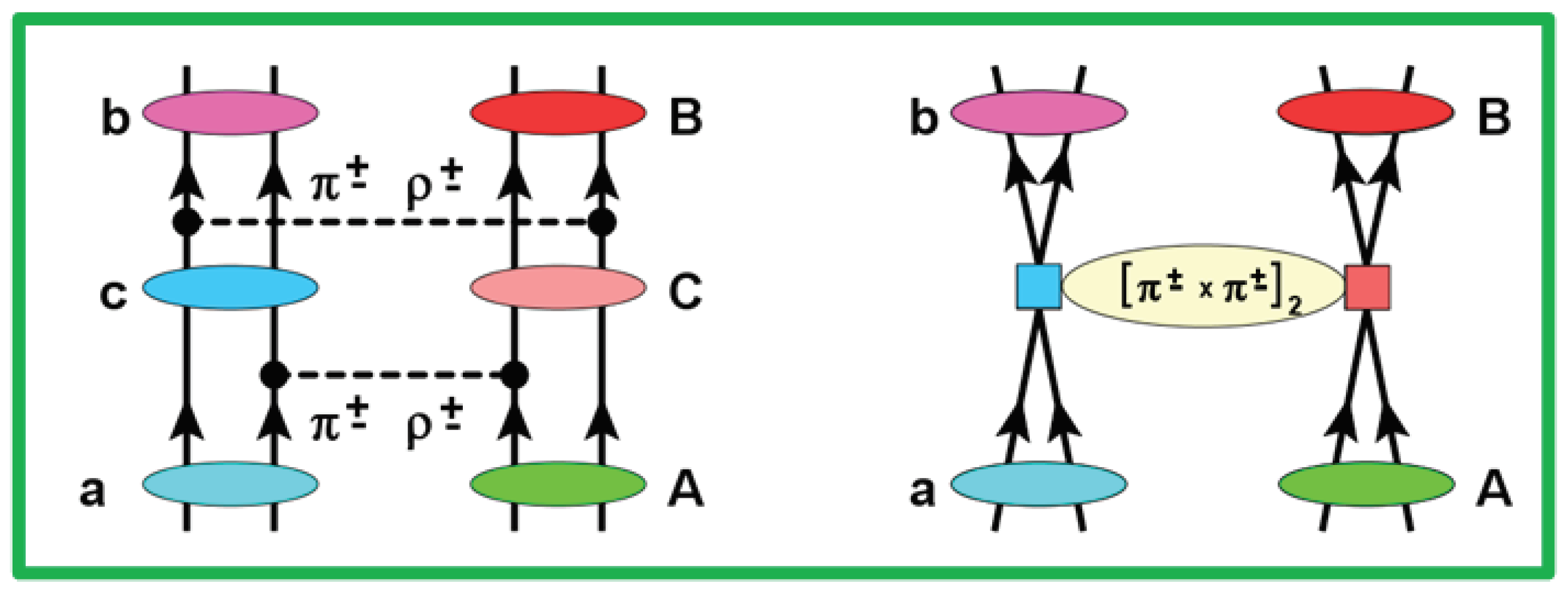
That deeper level of nuclear dynamics becomes visible only in collisional SCE and DCE processes. With nuclear physics methods the intrinsic isospin structure of the involved hadrons in a many–body environment can be probed in practise either by the exchange of virtual isovector mesons available by nucleon–nucleon (NN) isovector interactions or in pion–nucleon single and double charge exchange reactions. In a heavy ion DCE reaction, these two mechanisms appear in general simultaneously. The virtual meson exchange mechanism leads to the double single charge exchange (DSCE) reaction scenario, given by sequential actions of the NN T–matrix. DSCE is in competition with the Majorana DCE (MDCE) scenario given by a pair of virtual ( π ± , π ) reactions on projectile and target [1,2,4]. The two collisional DCE mechanisms are depicted in Figure 1.
An additionally appealing aspect of DCE physics is that the same nuclear configurations are accessed as in double beta–decay (DBD). DSCE reactions evolve by form factors which are of a similar diagrammatical structure than the nuclear matrix elements (NME) of two–neutrino ( 2 ν 2 β ) DBD. The MDCE form factors are described by diagrams which are of a striking similarity to those of neutrinoless ( 0 ν 2 β ) DBD. Moreover, DCE reactions and DBD processes proceed by the same kind of spin–isospin operators. However, the origin and strengths of coupling constants differ by orders of magnitude and the internal structure of the interaction vertices is fundamentally different.
Heavy ion reactions involve the complexities of strong initial state (ISI) and final state (FSI) interactions. They affect not only the size of cross sections and shape angular distributions but also the spectroscopy of the involved nuclei. Hence, an important part of DCE physics is to control and understand first elastic ion–ion interactions before safe, quantitative conclusions on the spectroscopic content of the data can be drawn. This problem is nothing new but is being investigated continuously since the early days of heavy ion physics. The optical model underlying direct nuclear theory provides the proper tools for quantitative descriptions of ISI/FSI effects, see e.g. [5]. The Multi-Methods-Approach used in the NUMEN project [2] is an indispensable component of experiment and theory in order to take care exactly of that problem. The successful description of DCE reaction data by combination of nuclear multi–step reaction theory and nuclear response function methods is found in [6]. In this work, we investigate that complexity under a different angle by addressing the interplay of ISI and FSI effects and DCE nuclear matrix elements.
New challenges and features are also encountered in nuclear response functions for second and higher order processes. Although in the past two or so decades a lot of experience has been collected on multi–particle–hole dynamics in low–lying nuclear excitations, see e.g. [7] for experiment and theory on double–photon emission, only little work has been spent on systematic investigations of nuclear DCE spectroscopy. At present, that gap is being closed by heavy ion DCE reactions. In a previous article [1] we have discussed already the theoretical methods required to convert second order nuclear reaction results, which are described in a t–channel formalism, to second order nuclear matrix elements, which are s–channel objects. In this article, we present an alternative approach by performing that transformation directly on the operator level with the advantage of obtaining deeper insight into the DCE dynamics and the interplay of reaction and structure physics. As an important result, we find that a DSCE reactions can also be understood as being caused by an effective isotensor interactions, created dynamically in a cooperative manner by the colliding ions.
The mentioned aspects will be discussed for the DSCE reaction mechanism, where the ISI/FSI complex is of general relevance for any second order nuclear reaction of distorted wave two–step character. The special features of relevance for the MDCE scenario will be addressed separately in a follow–up paper. In Section 2 second order DW reaction theory is recapitulated and the DSCE reaction amplitude is presented in standard second order form. The main result of Section 2, however, is the introduction of the closure approximation for the DSCE amplitude. In Section 3, an alternative, new formulation is presented for the DSCE reaction amplitude. The most important aspect is the separation of nuclear structure and reaction dynamics. Section 4 is devoted to the DSCE–NME. The t–channel operator structure of the product of T–matrices is recasted into s–channel two–body operators acting in projectile and target nucleus. Hence, we reconsider our previous formulation of that problem in [8] now on the level of operators, rather than on the level of matrix elements. The various aspects of the formalism are illustrated in Section 5. The discussed issues are summarized, conclusions are drawn, and an outlook to future work is given in Section 6. The multipole structure of the effective induced isotensor interaction is presented in a number of the appendices. The competing collisional MDCE mechanism by virtual π N DCE will be addressed in a follow–up paper.

2. Reaction Theory of Double Single Charge Exchange Reactions

2.1. The DSCE Propagator

Under reaction–theoretical aspects, the DSCE mechanism amounts to a two-step reaction
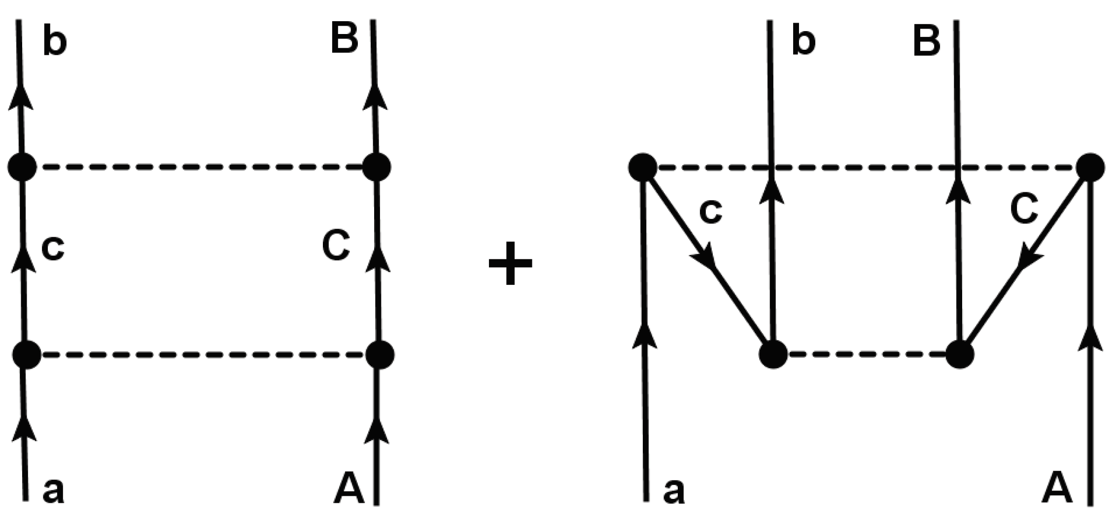
As depicted in Figure 1, DSCE reactions are a sequence of two single charge exchange events, each of them mediated by the two–body NN–isovector interaction T N N , the latter acting by one–body operators on the projectile and the target nucleus, respectively. For a reaction α = a ( Z a , N a ) + A ( Z A , N A ) β = b ( Z a ± 2 , N a 2 ) + B ( Z A 2 , N A ± 2 ) the reaction amplitude is written down readily as a quantum mechanical second order reaction matrix element [6]:
M α β ( 2 ) ( k α , k β ) = χ β ( ) , b B | T N N G a A ( + ) ( ω α ) T N N | a A , χ α ( + ) .
Initial (ISI) and final state (FSI) interactions are taken into account by optical potentials and the distorted waves χ α , β ( ± ) , depending on the center–of–mass (c.m.) momenta k α , β and obeying outgoing and incoming spherical wave boundary conditions, respectively. The available c.m. energy is ω α = s α , Denoting projectile and target nucleus by a and A, respectively, the available energy available in the center–of–mass rest frame s α = ( T l a b + M a + M A ) 2 T l a b ( T l a b + 2 M a ) . The perturbative approach of Eq. (1) is justified by the weak coupling of the DSCE channels to the elastic scattering channel. However, coupling to non–elastic channels cannot be excluded a priori and should be checked for each reaction [2].
The many–body Green’s function of the combined projectile–target system is denoted by G a A ( + ) . In operator form it is given by the resolvent of the projectile plus target many–body Schrödinger equation. Since DCE reactions are peripheral, grazing collisions, the a + A system remains in each reaction step separable into projectile and target nucleus, allowing to express the total Hamiltonian by the sum of the Hamiltonians H a and H A of the isolated nuclei plus the Hamiltonian H a A = H r e l + V a A . H r e l = T c m + U a A accounts for the kinetic energy of relative motion ( T c m ) and elastic ion–ion interactions ( U a A ) which for the assumed reaction scenario are well approximated by an optical model Hamiltonian H o p t . The residual projectile–target interactions are approximated the nucleon–nucleon (NN) T–matrix, V a A T N N , thus including the full Lippmann–Schwinger scattering series of NN–interactions. In a fully microscopic approach as in [6], U a A is calculated by in a folding approach by using T N N and nuclear ground state, typically derived self–consistently by functional methods like Hartree–Fock–Bogolyubov (HFB) theory [4].
As shown in Figure 2 the proper treatment of time ordering is taken care of by using the retarded propagator:
G a A ( + ) ( ω α ) = 1 ω α H a H A H o p t + i η + 1 ω α + H a + H A + H o p t + i η .
where the first and second term correspond to the ladder–graph and the so–called Z–graph, respectively. η 0 + denotes an infinitesimal, ensuring outgoing spherical wave boundary conditions by approaching zero from positive values.
The many–body wave function Ψ a A ( + ) with outgoing spherical scattering waves is expanded into the basis of eigenstates of the nuclear Hamiltonians, ( H a E c ) | c = 0 and ( H A E C ) | C = 0 , respectively. Hence, we obtain the representation:
G a A ( + ) ( ω α ) = γ = c C | c C G α γ ( + ) ( ω α ) c C |
leading to the channel propagators
G α γ ( + ) = 1 ω α E γ H o p t + i η + 1 ω α + M γ + H o p t + i η
which describe relative motion in a given partition | γ = | c C . The energy M γ = M c + M C + ε γ is given by the nuclear masses M c , C and the sum of excitation energies ε γ = ε c + ε C .
G α γ ( + ) is expanded into the bi–orthogonal set of optical model distorted waves (DW) being solution of the wave equation defined by H o p t [4,5,6,8]. This leads to the reduced propagators
g α γ ( + ) ( k γ ) = 1 ω α E γ T γ ( k γ ) + i η + 1 ω α + E γ + T γ ( k γ ) + i η
with the kinetic energy T γ ( k γ ) = k γ 2 + E c 2 + k γ 2 + E C 2 ( E c + E C ) k γ 2 2 m γ at the off–shell momentum k γ . 1 / m γ = 1 / E c + 1 / E C is the reduced mass. This allows to rewrite the DSCE reaction amplitude as
M α β ( 2 ) ( k α , k β ) = γ = { c , C } d 3 k γ ( 2 π ) 3 M γ β ( 1 ) ( k γ , k β ) g α γ ( + ) ( k γ ) M ˜ α γ ( 1 ) ( k α , k γ ) ,
The non–Hermitian nature of H o p t has led to two distinct half off–shell first order DWBA amplitudes [1,5,6]:
M ˜ α γ ( 1 ) ( k α , p γ ) = χ ˜ γ ( + ) , c C | T N N | a A , χ α ( + )
M γ β ( 1 ) ( p γ , k β ) = χ β ( ) , b B | T N N | c C , χ γ ( + ) ,
where χ ˜ γ ( + ) is the dual distorted wave obeying χ ˜ γ ( + ) | χ γ ( + ) = ( 2 π ) 3 δ ( k γ k γ ) δ γ γ .

2.2. DSCE Amplitude in Momentum Representation

The structure of the DSCE transition form factor becomes especially transparent when considered in momentum space. In momentum representation, the isospin–reduced, anti–symmetrized, energy dependent isovector T–matrix, acting between a nucleon in { a } and a nucleon in { A } , is given by the Fourier–Bessel transform [4,8]
T N N ( i , j ) = d 3 p ( 2 π ) 3 e i p · x i j T N N ( p ) .
In the ion–ion rest frame the relative distance between a nucleon i { a } and k { A } x i k = r k r i + r λ is given by the intrinsic nuclear coordinates r i , k and the ion–ion relative coordinate r λ , λ = α , β , the latter describing the distance between the center–of-mass of the projectile–like and the target–like nucleus.
SCE and DCE reaction are rely on isovector interactions. Hence, we choose as residual interaction the isovector ( T = 1 ) part of the NN T–matrix, consisting of central rank—0 spin–scalar, spin–vector and non–central rank-2 spin–tensor interactions:
T N N ( p | i k ) = S = 0 , 1 ; T = 1 V S T ( p 2 ) σ i · σ k S + δ S 1 V T n ( p 2 ) Y 2 ( p ^ ) · σ i σ k 2 τ i · τ k .
where only the isospin–ladder parts τ i , k ± are relevant for the SCE process. The (complex) form factors V S T and V T n , playing the role of variable coupling constants, are functions of the momentum transfer p and of the energies of the interacting nucleons. Y 2 M ( p ^ ) is a rank–2 spherical harmonics, above being contracted with a rank–2 spin–tensor. The spin-scalar parts excite Fermi–type (F) transitions, the spin–vector and spin–tensor components induce Gamow–Teller–type modes, mutually in projectile and target.
In momentum representation, the SCE transitions are described by matrix elements of the scattering operators
S N N ( p | i k ) = e i p ( r i r k ) T N N ( p | i k ) τ ± ( i ) τ ( j ) .
The plane wave factor accounts for the spatial multipole structure, resulting in the Bessel–Fourier transforms of the one–body transition densities, constructed from the n p 1 r p n 1 particle–hole configuration amplitudes and the corresponding single particle wave functions [4]. Odd indices i = 1 , 3 and even indices k = 2 , 4 will be used to denote states in the a– and the A–system, respectively.
The DSCE amplitude of Eq. (1) is the standard form for a DW matrix element in second order perturbation theory in T N N . In momentum representation, the DSCE reaction amplitude is retrieved, however, in a rather different form
M α β ( 2 ) ( k α , k β ) = d 3 p 1 d 3 p 2 d 3 k γ ( 2 π ) 3 K ^ α β ( p 1 , p 2 | k γ ) N α β ( p 1 , p 2 ) ,
Remarkably, the spectroscopic and reaction contribution appear in separated form. Nuclear spectroscopy is contained in the DSCE nuclear matrix element given by the form factor
N α β ( p 1 , p 2 ) = c C b B | S N N ( p 2 | ( 34 ) ) | c C g α γ ( + ) ( k γ ) c C | S N N ( p 1 | ( 12 ) ) | a A ,
where the reduced channel propagator g α γ ( + ) ( k γ ) depends on the energies of the intermediate states. The NME has the structure of second order perturbation theory. The formal similarity to the NME 2 ν –DBD is easily recognized.
Initial state (ISI) and final state (FSI) interactions are contained now completely in the reaction kernel
K ^ α β ( p 1 , p 2 | k γ ) = D ˜ α γ ( p 1 ) D γ β ( p 2 )
which is determined by the distortion coefficients [4]
D ˜ α γ ( p 1 ) = 1 ( 2 π ) 3 χ ˜ γ ( + ) | e i p 1 · r α | χ α ( + ) ; D γ β ( p 2 ) = 1 ( 2 π ) 3 χ β ( ) | e i p 2 · r β | χ γ ( + ) .

2.3. Closure Approximation

In the energy denominators of g α γ ( + ) contained in N α β we add and subtract a state–independent auxiliary energy ω γ and perform a Taylor–series expansion in ξ = 1 M γ ω γ . Since in leading order the propagator becomes independent of the intermediate states, the summations over the channel states c , C can be performed and we obtain the DSCE NME in closure approximation
F α β ( p 1 , p 2 ) = ( 13 ) { a } ( 24 ) { A } b B | R N N ( p 1 , p 2 | 13 , 24 ) | a A .
Initial and final nuclear states are connected directly by the effective DSCE rank–2 isotensor interaction
R N N ( p 1 , p 2 | 13 , 24 ) = S N N ( p 2 | 34 ) S N N ( p 1 | 12 ) .
The DSCE transition operator R N N is composed of a combination of two–body–operators, the one acting in projectile and the other in the target nucleus. Hence, in the combined projectile–target system R N N is an effective four–body interaction.
Attaching the modified, state–independent propagator to the reaction kernel and including also the k γ integration we obtain
K α β ( p 1 , p 2 ) = d 3 k γ ( 2 π ) 3 D γ β ( p 2 ) g α γ ( + ) ( k γ ) . D ˜ α γ ( p 1 ) .
The closure approach renders Eq. (12) into an intriguing simple form:
M α β ( 2 ) ( k α , k β ) = d 3 p 1 d 3 p 2 K α β ( p 1 , p 2 ) B α β ( p 1 , p 2 ) + R e s ( ξ ) ,
where terms of first and higher order in ξ are contained in R e s ( ξ ) .

3. The DSCE Reaction Kernel and Initial and Final State Interactions

3.1. The Reaction Kernel in Plane Wav Approximation

An instructive – albeit unrealistic – limiting case is to neglect all elastic interactions leading to the plane wave approximation (PWA). In PWA the distortion coefficients, Eq. (15), achieve a particular simple form, D ˜ α γ = δ ( q α γ + p 1 ) and D γ β = δ ( q γ β + p 2 ) , respectively, where q α γ = k α k γ and q γ β = k γ k β are the half off–shell momentum transfers in the first and second SCE interaction. The total on–shell momentum transfer is q α β = q α γ + q γ β .
Changing the momentum coordinates to p 1 , 2 P ± q / 2 , and introducing the mean on–shell channel momentum P α β = ( k α + k β ) / 2 , the product of PWA distortion factors and the k γ –integral are easily evaluated, resulting in the PWA reaction kernel
K α β ( 0 ) ( P , q ) = 1 8 δ ( P + 1 2 q α β ) g α γ ( + ) ( | P α β q / 2 | ) .
Both the delta–distribution and the functional structure of the propagator impose constraints on the momenta P and q .1 The above result indicates also that P , i.e. the sum of the momenta p 1 and p 2 , is closely related to the physical momentum transfer q α β .

3.2. Distortion and Absorption

In order to gain insight in the effects introduced by adding ISI/FSI interactions we use a simple but realistic approach: The product of distorted waves is factorized into a plane wave part and a reduced, in general complex–valued, amplitude:
χ ˜ γ ( + ) ( r α ) χ α ( + ) ( r α ) e i ( k α k γ ) · r α η ˜ α γ ( r α )
χ β ( ) ( r β ) χ γ ( + ) ( r β ) e i ( k γ k β ) · r β η γ β ( r β ) .
For strongly absorbing systems like colliding heavy ions the reduced DW–amplitudes are strongly suppressed in the overlap region, as is easily verified in Wentzel–Kramers–Brillouin (WKB) or eikonal theory. That region, centered at the origin, corresponds to an avoided volume in the sense that the spatial density distributions of the incoming and outgoing distorted waves vanishes. This kind of localized absorption of probability implies that the (quantum mechanical) survival probability of the initial system in that region is approaching zero. As a consequence, reactions will be restricted to regions outside of the ion–ion overlap volume, characterized by a strong probability flux into other reaction channels.
The shape and extension of that void is imprinted in the reduced amplitude. Describing the shape and size of the probability voids by the absorption form factors | h i j ( r ) | we obtain η i j ( r ) = 1 h i j ( r ) . For heavy ion reactions | h i j ( r ) | is unity up to the absorption radius r = R a b s and decreases rapidly at larger radii [4],in many aspects resembling a Heaviside distribution h i j ( r ) Θ ( R a b s 2 r 2 ) . In Ref. [4] it was shown that R a b s is directly related to the total ion–ion reaction cross section, varying with energy and increasing with the mass numbers of the interacting nuclei.
Since for a given reaction h i j is fixed essentially by the entrance channel, we may use universal form factors, h i j ( r ) H S ( r ) and η ˜ i j H ¨ ˜ S ( r ) . Thus, we obtain
D ˜ α γ ( p 1 ) = δ ( p 1 + q α γ ) H ˜ S ( p 1 + q α γ )
D γ β ( p 2 ) = δ ( p 2 + q γ β ) H S ( p 2 + q γ β ) .
Hence, with ISI/FSI interactions the distortion factors are given by subtracting the interactions occurring in the avoided volume from the maximal possible interaction probability density described by the PWA delta-distribution.
In DWA the DCE reaction kernel is found to be given by the PWA–kernel with a unit interaction probability density, which is corrected for the overcounting of reaction probability by subtracting the interaction probability densities related to the avoided volume:
K α β ( p 1 , p 2 ) = K α β ( 0 ) ( p 1 , p 2 ) + K α β ( 1 ) ( p 1 , p 2 ) + K α β ( 2 ) ( p 1 , p 2 ) .
The two–step character of the DSCE reaction amplitude is reflected by the first and second order kernels K α β ( 1 ) and K α β ( 2 ) , respectively. With the { P , q } coordinates, the first order absorption kernel is found as
K α β ( 1 ) ( P , q ) = d 3 k γ ( 2 π ) 3 g α γ ( + ) ( k γ ) ( δ ( P + q / 2 + q α γ ) H S ( P q / 2 + q γ β ) + δ ( P q / 2 + q γ β ) H ˜ S ( P + q / 2 + q α γ ) ) .
Performing the k γ –integration the result is
K α β ( 1 ) ( P , q ) = 1 ( 2 π ) 3 ( H S ( 2 P + q α β ) g α γ ( + ) ( | P + q / 2 + k α | ) + H ˜ S ( 2 P + q α β ) g α γ ( + ) ( | P q / 2 k β | ) ) .
Considering that H S ( Q ) has a pronounced maximum at Q = 0 we may replace
K α β ( 1 ) ( P , q ) 1 ( 2 π ) 3 H S ( 2 P + q α β ) + H ˜ S ( ( 2 P + q α β ) g α γ ( + ) ( | P α β + q / 2 | ) .
Using H S = e 2 i Φ F S and H ˜ S e 2 i Φ ˜ F S , we obtain
K α β ( 1 ) ( P , q ) 2 ( 2 π ) 3 e i ϕ cos ( ϕ ) F S ( 2 P + q α β ) g α γ ( + ) ( | P α β + q / 2 | ) ,
with ϕ = Φ + Φ ˜ where the phases may depend on momentum.
The kernel of second order in the absorption form factors is
K α β ( 2 ) ( P , q ) = d 3 k γ ( 2 π ) 3 g α γ ( + ) ( k γ ) H ˜ S ( ( 2 P + q / 2 ) + q α γ ) H S ( ( 2 P q ) / 2 + q γ β ) .
The product of form factors is evaluated easily by going back to the definition of the form factors F S as Fourier–Bessel transforms and interchanging the order of momentum and radial integrations. The detailed description in Appendix B leads to the conclusion that to a good approximation the kernel separates into a product of P– and q–dependent form factors
K α β ( 2 ) ( P , q ) F α β ( 2 ) ( 2 P + q α β ) g α γ ( + ) ( | P α β + 1 2 q | ) .
where
F α β ( 2 ) ( 2 P + q α β ) = d 3 r e i ( 2 P + q α β ) · r H ˜ S ( r ) H S ( r ) .
Collecting results, we obtain the total reaction kernel
K α β ( P , q ) = g α γ ( + ) ( | P α β + 1 2 q | ) × 1 8 δ ( P + q α β / 2 ) e i ϕ ( 2 π ) 3 2 cos ( ϕ ) F S ( 2 P + q α β ) e i ϕ F ¯ S ( 2 ) ( 2 P + q α β ) .
A phase factor was extracted from the last term, F ¯ S ( 2 ) e 2 i ϕ F α β ( 2 ) . The factorized q and P dependence is still maintained.
Finally, the P and q integrations are performed and as the main result of this section, we obtain the DSCE reaction amplitude
M α β ( 2 ) ( k α , k β ) ) = d 3 q g α γ ( + ) ( | 1 2 q + P α β | ) 1 8 B α β ( 1 2 q α β , q ) d 3 P B α β ( P , q ) D α β ( P , q α β )
where we have introduced the distortion form factor accounting for the interaction effects induced by the kernels K α β ( 1 , 2 ) and being used in the form
D α β ( P , q ) = e i ϕ ( 2 π ) 3 2 cos ( ϕ ) F S ( 2 P + q ) e i ϕ F ¯ S ( 2 ) ( 2 P + q ) .
Further insight is gained by expressing the propagator by the Fourier transform of the coordinate space propagator
g α γ ( + ) ( x ) = d 3 k ( 2 π ) 3 e i k · x g α γ ( + ) ( k ) = 1 4 π x e i k + x + e i k x ,
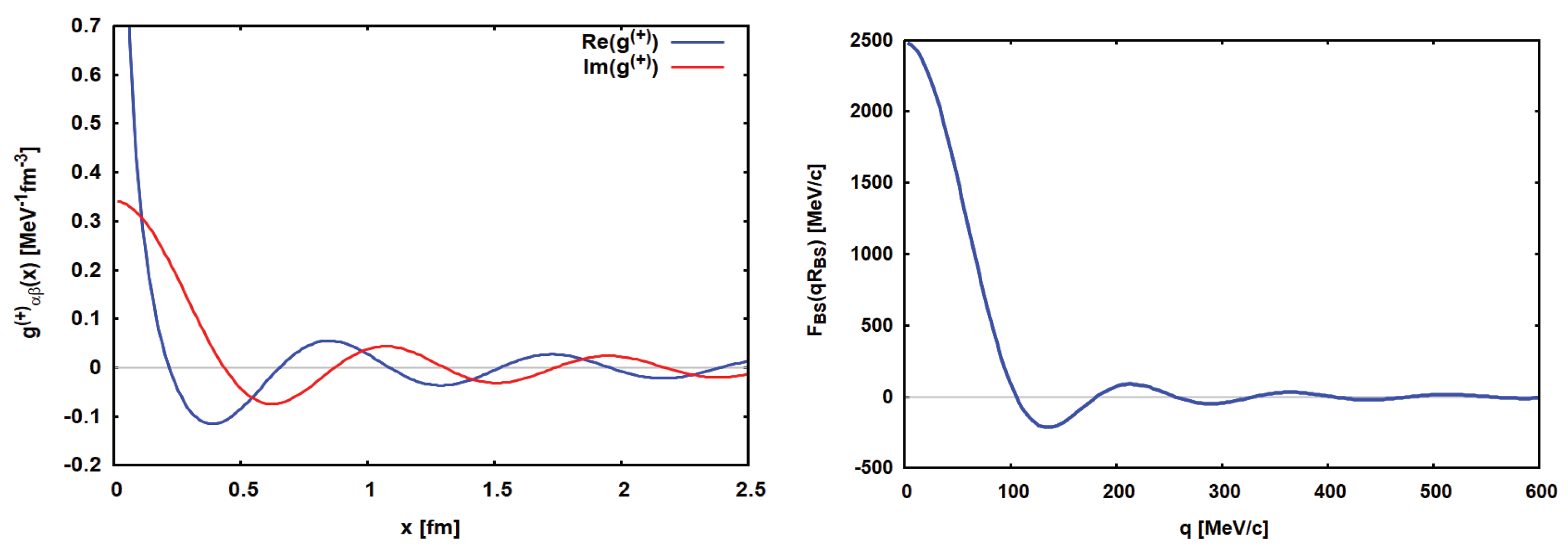
where k + = ω α 2 ω γ 2 and k = i ω α 2 + ω γ 2 denote the poles of g α β ( + ) ( k ) in the upper and lower complex half–planes, respectively. In Figure 3 the propagator is displayed as encountered in the reaction   40 Ca ( 18 O , 18 Ne ) 40 Ar at T l a b = 270 MeV.

3.3. Momentum Structure of the Nuclear Matric Element

The DSCE–NME defined by
F α β ( p 1 , p 2 ) = 1 3 { a } 2 4 { A } b B | e i p 2 · ( r 3 r 4 ) T N N ( p 2 | 34 ) T N N ( p 1 | 12 ) e i p 1 · ( r 2 r 2 ) | a A ,
deserves a more detailed consideration because care has to be taken to avoiding overcounting. This means to exclude that the same nucleon takes part in the first end the second SCE events. Most elegantly, this is achieved by using the coordinates { P , q } and center and relative spatial coordinates { r μ , x μ } , μ = ( 13 ) or μ = ( 24 ) , respectively. Hence, we replace p 1 , 2 = P ± q / 2 and r 1 , 3 = r 13 / 2 ± x 13 and accordingly r 2 , 4 = r 24 / 2 ± x 24 . Furthermore, for the sake of focusing on the essential features and a more transparent formulation, the momentum dependence of T–matrices is approximated by p 1 , 2 q α β / 2 which is eligible considering that p 1 + p 2 q α β . Thus, we introduce
U N N ( q α β | 12 , 34 ) = T N N ( p 2 | 34 ) T N N ( p 1 | 12 ) | p 1 = p 2 = q α β / 2 .
Then, the exclusion principle is treated properly by using
  F α β ( P , q ) 4 1 , 3 { a } 2 , 4 { A } b B | e i P · ( r 13 r 24 ) U N N ( q α β | 12 , 34 ) sin ( q · x 13 ) sin ( q · x 24 ) | a A ,
which vanishes for i = j and changes sign under exchanges 1 3 and 2 4 , respectively.
At this point it is of advantage to incorporate again the propagator into the nuclear matrix element such that the q–integration can be performed:
B α β ( K , P α β ) = d 3 q g α γ ( + ) ( | 1 2 q + P α β | ) F α β ( K , q ) .
Thus, the second order dynamics originally introduced as a reaction dynamical effect has been converted to a spectroscopic property. The DSCE reaction amplitude is obtained in the compact and intuitive form
M α β ( 2 ) ( k α , k β ) ) = 1 8 B α β ( 1 2 q α β , P α β ) d 3 P B α β ( P , P α β ) D α β ( P , q α β ) .
The plane wave matrix element describes the unit DCE interaction probability without ISI/FSI, thus representing the maximal DCE transition strength. The second component corresponds to a fictitious DCE process occurring in the avoided ion–ion overlap volume. As a result, the heavy ion DCE amplitude is determined by the subtraction of the reaction dynamical forbidden matrix element from the unconstrained plane wave matrix element of unit interaction probability.

3.4. Induced DSCE Correlations

From Eq. (39) it is found that the q–dependence is separated, being completely contained in product of the two sine–functions. The q–integral is easily performed by substituting k = q / 2 + P α β . We also introduce x ± = x 13 ± x 24 . The addition theorems of trigonometric functions yield:
C ( k , P α β ) = 4 sin ( ( k P α β ) · x 13 ) sin ( ( k P α β ) · x 24 )
= 2 C ( k , P α β ) C + ( k , P α β ) ,
where
C ± ( k , P α β ) = cos ( k · x ± ) cos ( P α β · x ± ) + sin ( k · x ± ) sin ( P α β · x ± ) .
A closer look shows that the k–integral serves to project on the monopole component of the integrand. By symmetry reasons only the cosine–terms will contribute, leading to
Γ ( P α β | x 13 , x 24 ) = 8 d 3 k g α γ ( + ) ( k ) 2 cos ( k · x ) cos ( P α β · x ) 2 cos ( k · x + ) cos ( P α β · x + ) .
Contour integration leads to the correlation function
Γ ( P α β | x 13 , x 24 ) = 64 π 3 g α β ( + ) ( k 0 x ) cos ( P α β · x ) g α β ( + ) ( k 0 x + ) cos ( P α β · x + ) . .
From the functional properties of the reduced propagators g α β ( + ) ( k 0 x ± ) , we conclude that the regions x ± = x 13 ± x 24 0 are weighted most strongly. Since x 13 and x 24 denote the distances between two SCE vertices in the interacting nuclei, respectively, we find that the relative motion has induced a pronounced correlation corresponding to constraining the vertices to appear at x 13 ± x 24 . Thus, we encounter a configuration of two coupled isospin–dipoles, combined to an isospin quadrupole where the two dipoles are separated by Δ x = | x 13 | = | x 24 | , with a fluctuation δ x c / k 0 . Remembering that the pole momentum k 0 depends on the ion masses, the nuclear excitation energies, and the kinetic energy, the magnitude of the fluctuation will vary such that increasing any of those conditions will decrease the quantal fluctuations and vice versa. The interference of the two kind of dipoles x + and x , respectively, is determined mainly by the monopole component given by a Riccati–Bessel function j 0 ( x )
cos ( P α β · x ± ) j 0 ( P α β x ± ) + O ( j 2 ( P α β x ± ) ) .
The quadrupole and higher order contributions - by symmetry reasons of only even multipolarity – are suppressed because the functions j 2 n ( x ) , n 1 , will gain strength only at larger distances considerably beyond the effective range defined by the propagator.
Another look to the correlated DSCE–NME
  B α β ( K | k α , k β ) = 1 , 3 { a } 2 , 4 { A } b B | e i K · ( r 13 r 24 ) U N N ( q α β | 12 , 34 ) Γ ( P α β | x 13 , x 24 ) | a A .
reveals that also the total momentum transfer variable K induces a correlation exists. As seen above, K imposes a constraint on the center coordinates of the nucleon pairs, r 13 r 24 within an interval of the order δ r 1 / K . In the plane wave part of the NME, where K = 1 2   q α β , the correlation length varies with the scattering angle. As seen in Eq. (41), the distortion part of the NME reaction amplitude is given by folding B α β with the momentum distribution of the DCE distortion form factor. Using Eq. (48), the P–integration reduces to evaluate a Bessel–Fourier integral, mapping the distortion amplitude from momentum space to r–space:
D α β ( r 13 r 24 , q α β ) = d 3 P ( 2 π ) 3 e i P · ( r 13 r 24 ) D α β ( P , q α β ) .

4. Transformation of the DSCE Interactions and Nuclear Matrix Elements

4.1. The DSCE Two–Body Isotensor Interaction

The closure approximation has led to effective two–body interactions R N N acting in the projectile and target nuclei, and corresponding in total to a nucleus-nucleus four–body interaction. As indicated in Fig. 2 by the ladder diagram, originally the interactions carry an operator structure defined by the t–channel formalism as appropriate for a nuclear reaction. Nuclear matrix elements, however, are defined within a given nucleus which requires a transformation of the operators into a s–cannel formalism. In Ref. [8] that problem was solved on the level of matrix elements. Here, we address that question from the operator side by appropriate reordering of operators and applications of angular momentum recoupling techniques.
We introduce the rank–2 isotensor operator
I 2 ( 13 | 24 ) = τ ± ( 1 ) τ m p ( 3 ) | a τ ( 2 ) τ p m ( 4 ) | A .
and defining
R N N ( p 1 , p 2 | 13 , 24 ) = S N N ( p 2 | 34 ) S N N ( p 1 | 12 )
the effective rank–2 isotensor interaction is rewritten as
R N N ( p 1 , p 2 | 13 , 24 ) = R N N ( p 1 , p 2 | 13 , 24 ) I 2 ( 13 | 24 ) .
Since the isotensor is already in s–channel form, in the following we need to consider only the reduced DSCE interaction R N N .
From the operator structure of the NN T–matrix, we derive immediately that R N N is a superposition of products of spin–scalar, spin–vector, and rank–2 spin–tensor interactions. For the rank–0 central interactions with T = 1 we derive for example the structure:
R N N ( 0 ) ( p 1 , p 2 | 13 , 24 ) = S , S = 0 , 1 σ 3 · σ 4 ] S U S S ( p 1 , p 2 ) [ σ 1 · σ 2 ] S .
and corresponding expression are recovered for the tensor interaction and the mixed central–tensor terms. Hence, we find the vertex form factors
U S S ( p , p ) = V S T ( p ) V S T ( p )
U T n T n ( p , p ) = V T n T ( p ) V T n T ( p )
U S T n ( p , p ) = V S T ( p ) V T n ( p )
U T n S ( p , p ) = V T n T ( p ) V S T ( p ) .
They are playing the role of momentum dependent effective coupling constants, in addition varying also with the energy in the NN rest frame.
While for spin–scalar interactions the t– to s–channel transformation is trivial, the spin–dependent interactions require a considerably more involved treatment by explicit angular momentum recoupling. Since also the spacial degrees of freedoms have to be treated properly, we define the spin–scalar and spin–vector operators
R 0 ( k | i ) = e i k · r i 1 σ ; R 1 ( k | i ) = e i k · r i σ i ,
where 1 σ is the spin–unity operator. k = p for i = 1 , 3 in the a–system and k = p for i = 2 , 4 in the A–system.
The rank–0 central interactions lead to a superposition of Fermi–Fermi (FF), Gamow-Teller–Gamow-Teller (GG) and the mixed Fermi–Gamow–Teller transitions, FG and GF. Leaving aside from hereon the vertex form factors, the resulting operators are
Σ F F ( p 1 , p 2 | 13 , 24 ) = R 0 ( p 1 | 1 ) R 0 ( p 2 | 3 ) R 0 ( p 1 | 2 ) R 0 ( p 2 | 4 )
Σ F G ( p 1 , p 2 | 13 , 24 ) = R 0 ( p 2 | 3 ) R 1 ( p 1 | 1 ) · R 1 ( p 1 | 2 ) R 0 ( p 2 | 4 )
Σ G F ( p 1 p 2 | 13 , 24 ) = R 0 ( p 1 | 1 ) R 1 ( p 2 | 3 ) · R 1 ( p 2 | 4 ) R 0 ( p 1 | 2 ) .
While the FF and FG/GF components are already in an appropriate form, the double Gamow–Teller operators (GG) require a more detailed treatment. The products of spin–vector components are recoupled by arranging the nucleon spin operators into intra–nuclear two–body operators of tensorial rank 0,1,and 2 which by contraction form a total rank–0 scalar operator in the overall projectile–target system:
Σ G G ( p 1 , p 2 | 13 , 24 ) = S = 0 , 1 , 2 R 1 , ( p 1 | 1 ) R 1 ( p 2 | 3 ) S · R 1 , ( p 1 | 2 ) R 1 ( p 2 | 4 ) S
where the S = 0 components are in fact scalar products, R 1 ( p 1 | i ) · R 1 ( p 2 | j ) .
An even richer spectrum of operators is obtained from the double–tensor (TT) term. Labeling for bookkeeping reasons the nucleon spin–operators by S i , where S i = 1 , defining S i j = 2 , using J ^ = 2 J + 1 , and applying angular momentum recoupling techniques which result in a 9–j symbol, one finds
Σ T n T n ( p 2 , p 2 | 13 , 24 ) = S ^ 12 S ^ 34 S a , S A = 0 , 1 , 2 S ^ a S ^ A S = | S a S A | S a + S A S 1 S 2 S 12 S 3 S 4 S 34 S a S A S × Y S 34 ( p ^ ) Y S 12 ( p ^ ) S · R 1 ( p | 1 ) R 1 ( p | 3 ) S a R 1 ( p | 2 ) R 1 ( p | 4 ) S A S .
The mixed central–tensor terms include the Fermi–Tensor components FT and TF
Σ F T ( p 1 , p 2 | 13 , 24 ) = R 0 ( p 2 | 3 ) Y 2 ( p ^ 1 ) · R 1 ( p 1 | 1 ) R 1 ( p 1 | 2 ) 2 R 0 ( p 2 | 4 )
Σ T F ( p 1 , p 2 | 13 , 24 ) = R 0 ( p 1 | 1 ) Y 2 ( p ^ 2 ) · R 1 ( p 2 | 3 ) R 1 ( p 2 | 4 ) 2 R 0 ( p 1 | 2 ) .
With appropriate recoupling, the combined Gamow–Teller–Tensor (GT) components become
Σ G T ( p 1 p 2 | 13 , 24 ) = L ^ 2 S a , S A = 1 , 2 S ^ a S ^ A S 1 S 2 L S 3 S 4 0 S a S A L × Y L ( p ^ ) · R 1 ( p 1 | 1 ) R 1 ( p 2 | 3 ) S a R 1 ( p 1 | 2 ) R 1 ( p 2 | 4 ) S A L ,
with L = 2 . Accordingly,
Σ T G ( p 1 , p 2 | 13 , 24 ) = L ^ 2 S a , S A = 1 , 2 S ^ a S ^ A S 1 S 2 0 S 3 S 4 L S a S A L × Y L ( p ^ 2 ) · R 1 ( p 1 | 1 ) R 1 ( p 2 | 3 ) S a R 1 ( p 1 | 2 ) R 1 ( p 2 | 4 ) S A L .

4.2. DSCE Form Factors and Spectroscopy

The DSCE transition form factor is given by
F α β ( p 1 , p 2 ) = i j { a } , k l { A } b B | R N N ( p 1 , p 2 | i j , k l ) | a A ,
generalizes the concept of nuclear matrix elements to transition form factors of arbitrary momentum transfers. Nuclear matrix elements in the strict sense are recovered in the limiting case p , p 0 .
A key question is what kind of spectroscopic information can be extracted from DSCE cross sections. For an answer, we have to have a closer look into the operator structure, given by multitude of terms. Already from the central spin–vector interactions two additional spin-tensor terms were obtained by recoupling. But most of the components are generated by the additional degrees of freedom provided by the rank–2 spin–tensor interactions. Counting the recoupling terms separately, more than 40 components are recognized. However, they are actually determined by four generic types of operators, namely the spin scalar–scalar terms, mixed scalar–vector and scalar–tensor, and rank–1 and rank–2 tensor terms. Moreover, by the plane wave parts, the scalar R 0 and vector R 1 operators contain a rich spectrum of multipole operators by expanding the plane wave factors into partial waves as discussed in Appendices Appendix C and Appendix D, respectively. After reordering, each of the terms factorizes into a projectile and a target form factor but in general F α β as a whole will not be separable in a a– and a A–type form factor.
As an example, we consider Σ F G and introduce the partial form factor
F α β ( F G ) ( p , p ) = μ ( ) μ F a b , μ F G ( p , p ) F A B , μ F G ( p , p )
where the isospin matrix elements were left out for simplicity and the scalar product is evaluated explicitly in the spherical bi–orthogonal basis { e μ * , e μ } , μ = 0 , ± 1 , see Appendix D. The form factors in the a– and the A–system, respectively, are defined as:
F a b ( F G ) ( p , p ) = ( 13 ) b | R 1 ( p | 3 ) R 0 ( p | 1 ) | a = μ F a b , μ ( F G ) ( p , p ) e μ *
F A B ( F G ) ( p , p ) = ( 24 ) B | R 1 ( p | 4 ) R 0 ( p | 2 ) | A = μ F A B , μ ( F G ) ( p , p ) e μ * .
Both form factors are given by products of spin–scalar and spin–vector operators, the latter expressed in spherical representation, following the rules discussed in the Appendix.
The DSCE nuclear form factors and NMEs are given by a superposition of terms which are factorized into a projectile and a target NME. However, in general a complete separation into a single product of nuclear NMEs is rather unlikely, even for 0 + 0 + DCE transitions in both reaction partners. As an example, we consider the A ( 0 + ) B ( 0 + ) case. Obviously, the total angular momentum transfer is restricted to J π = 0 + . However, by a two–body operator that transition can be achieved in at least two ways, namely by the total monopole part of the FF operator R 0 ( p | 1 ) R 0 ( p | 3 ) J = 0 or by the coupling of the total orbital/spin quadrupole components of the GG–operator coupled to a monopole operator, R 1 ( p | 1 ) R 1 ( p | 3 ) ( L = S = 2 ) J = 0 . Excitations of states with higher angular momentum will enlarge the number of allowed contributions considerably.

4.3. Direct Evaluation of the Nuclear Matrix Elements

Although the investigations in the foregoing section are of high value to understand the dynamics of DCE transitions induced by NN interactions, they may not be the most favorable approach for practical numerical calculations. Moreover, the formalism seems to be quite different from the one derived in Ref. [8] which led to rank–2 polarization tensors resembling 2 ν 2 β –NME. In the following, we show that in fact the present and former results are in perfect agreement.
Going back to Eq. (51), we may separate the product of T–matrices by insert the unity operator at the proper place and find:
B α β ( p , p | 13 , 24 ) = c , C B | S N N ( p | 34 ) | c C · c C | S N N ( p | 12 ) | a A
thereby reversing closure by re–installing the spectrum of intermediate states. Contraction to a total scalar is indicated by the dot–product. With the presentation of S N N in terms of product of one-body spin–scalar and spin–vector operators R 0 ( p | i ) and R 1 ( p | i ) , respectively, we obtain
B α β ( p , p | 13 , 24 ) = S 1 , S 2 V S 1 T ( p ) V S 2 T ( p ) · B S 1 S 2 ( p , p | a b ) B S 1 S 2 ( p , p | A B ) ,
and the spin–tensor terms are teated analogously. The projectile and target NME are
B S 1 S 2 ( p , p | a b ) = c { a } b | R S 2 ( p | 3 ) | c c | R S 1 ( p | 1 ) | a
B S 1 S 2 ( p , p | A B ) = C { A } B | R S 2 ( p | 4 ) | C C | R S 1 ( p | 2 ) | A .
The relation to the polarization tensor formalism developed in [8] is seen by re-writing the NME in the form of a contour integral over a rank–2 polarization tensor:
B S 1 S 2 ( p , p | a b ) = 1 2 i π d ω c { a } b | R S 2 ( p | 3 ) | c 1 E c ω + i η c | R S 1 ( p | 1 ) | a .
The NME of the A–system is treated accordingly. Performing a multipole expansion as needed for nuclear spectroscopy, the coupling schemes developed in the previous section must be applied.

5. Illustrative Applications for DSCE Reactions

5.1. The Back Sphere Limit

Explicit calculations for strongly absorbing systems like interacting heavy ions the shape of the modulus resembles a Heaviside distribution H i j ( r ) Θ ( R a b s r ) , where the absorption radius R a b s is closely related to the total reaction cross section [4]. Thus, the defining features of the reaction kernels are well described by the Bessel–Fourier transform of a Heaviside distribution, known as the Black Sphere form factor h B ( x ) = 3 j 1 ( x ) / x , h B ( 0 ) = 1 , where x = k R a b s and j 1 ( x ) is a spherical Riccati–Bessel function. The reduced absorption form factor and the Black Sphere (BS) form factor are related by
F S ( k ) F B S ( k ) = R a b s 3 6 π 2 h B ( k R a b s ) .
The form factor h B ( x ) , describing the excluded, absorptive overlap region, becomes in momentum space a distributions centered at x = 0 with a full width at half maximum Γ B S a p p r o x 3 π 2 R a b s , Since R a b s = R a b s ( A P , A T ) , Γ B S decreases with increasing mass numbers A P , T and F B S approaches a delta–distribution.
We also note that in the Black Sphere limit one finds
F α β ( 2 ) ( P | q α β ) ( R a b s ( 2 ) ) 3 6 π 2 e i ϕ h B ( | P + q α β | R a b s ( 2 ) ) .
In the extreme limit R a b s ( 2 ) = R a b s , the kernel gains an intriguing simple form:
K α β ( P , q ) g α γ ( + ) ( | P α β + 1 2 q | ) δ ( P + q α β ) 1 6 π 2 R a b s 2 π 3 h B ( | P + q α β | R a b s )
The minus sign indicates the sizable reduction of the DSCE cross section by several orders of magnitude due to cancellation of the plane wave part by the absorption exerted by the imaginary part of the ion–ion optical potential. In the following case studies, the BS approximation will be used, mainly because of its especially transparent structure and easy reproducibility.

5.2. Form Factors of the Rank–2 DSCE Interaction

The approach discussed in the previous sections has been applied to the DCE reaction   40 Ca ( 18 O , 18 Ne ) 40 Ar at T l a b = 270 MeV, measured at LNS Catania [9]. The absorption radius leads for the   18 O + 40 Ca system to The absorption radius R a b s 8.40 fm was derived from the total reaction cross section σ r e a c = 2.218 b in the incident channel, obtained with a double folding potential using the Hartree–Fock–Bogolyubov (HFB) ground state densities of the A=18 and A=40 nuclei and a NN T–matrix derived for low NN–energies in Love–Franey parametrization [2,4,10].
For that reaction the propagator contains a real–valued pole at k 0 2017 MeV/c, corresponding to a kinetic energy T 0 175.89 MeV if in the intermediate channel excitation energies are neglected. Adding excitation energy will move the pole to lower values of k 0 but qualitatively the same results are obtained. As seen in Figure 3, the propagator g α β ( + ) ( x ) is narrowly peaked at small distances x, confirming the mentioned strong localization around x 0 .
Figure 3. The propagator g α γ ( + ) ( x ) for the reaction   40 Ca ( 18 O , 18 Ne ) 40 Ar at T l a b = 270 MeV with k 0 2017 MeV/c is shown on the left. The real part (blue) and the imaginary part (red) are shown separately. On the right, the Black Sphere distribution for the BS–radius R a b s = 8.40 fm is displayed.
Preprints 95494 g003
The displayed results Under the chosen kinematical conditions, the shapes of the isotensor form factors are strongly dominated by the pole of the propagator g ( + ) ( k ) at k 0 = 2 m γ ( ω α ω γ ) 2016 MeV/c. That kind of dominance is maintained essentially also for other kinematical conditions, confirming that the k–integration will indeed be determined by the form factors and transition densities at the corresponding momenta. Numerical results show that in the energy region covered by the NUMEN experiment the form factors involving the central spin–vector interaction V 1 T are by far the ones of largest magnitude. That behaviour persist also under other kinematical conditions. These results are indicating that in the considered reaction Gamow–Teller-type transitions will be favored by the DSCE interaction.
The interaction form factors are to be combined with the nuclear transition densities in the interacting nuclei. After integration over k the nuclear matrix elements will be obtained as seen by choosing K = q α β and substituting q k = 1 2 q + P α β . Then, the NME can be rewritten as:
B α β ( k α , k β ) = 1 8 d 3 k g α β ( + ) ( k ) B α β ( k α k , k k β ) ,
which is the NME of the plane wave part of the reaction amplitude and as such, is not affected by initial and final state interactions. In Ref. [6], an example of the pane wave NME is found for the repeatedly mentioned DCE reaction by   18 O + 40 Ca.
As worked out before in [8], in general the DSCE nuclear matrix elements are composed of various combinations of multipole transitions in the interaction nuclei, coupled to the total angular momentum transfer observed in the angular distributions of DCE cross sections. Insight into the hidden multipole structure is obtained from an expansion of the amplitude B α β into multipoles with respect to the scattering angle θ c m = θ α β :
B ¯ α β ( k α , k β ) = π 2 ( 2 + 1 ) P ( cos θ c m ) B ¯ ( k α , k β ) ,
B ¯ ( k α , k β ) = 0 d k k 2 g α γ ( + ) ( k ) B ( k | k α , k β ) ,
where the z–axis was chosen in direction of k α . An interesting approach is the pole approximation for the propagator [6], leading in the present case to
B ¯ ( 0 ) ( k α , k β ) = i π m γ k 0 B ( k 0 | k α , k β ) ,
which is a scalar functional of the NN T–matrices and the nuclear wave functions.
From the definition of the NME one finds that the multipole components B ¯ are always given by combinations of intrinsic nuclear multipoles with multipoles of the NN interaction form factors U i j . Hence, one has to take onto account that measurements will always lead to observation of intrinsic nuclear transition strengths combined with the NN vertices. However, that is by mo means a special feature of nuclear reactions but the same is true for any another probe, electromagnetic response functions are necessarily in units of the electric charge, weak processes are connected with the vector and axial–vector coupling constants, where at least the latter are carrying momentum depend form factors as well [11]. The essential difference of nuclear DCE reactions to the electro–weak cases is that measurements will always observe the combined response of the projectile and the target nucleus.

5.3. The DSCE Cross Section in BS Approximation

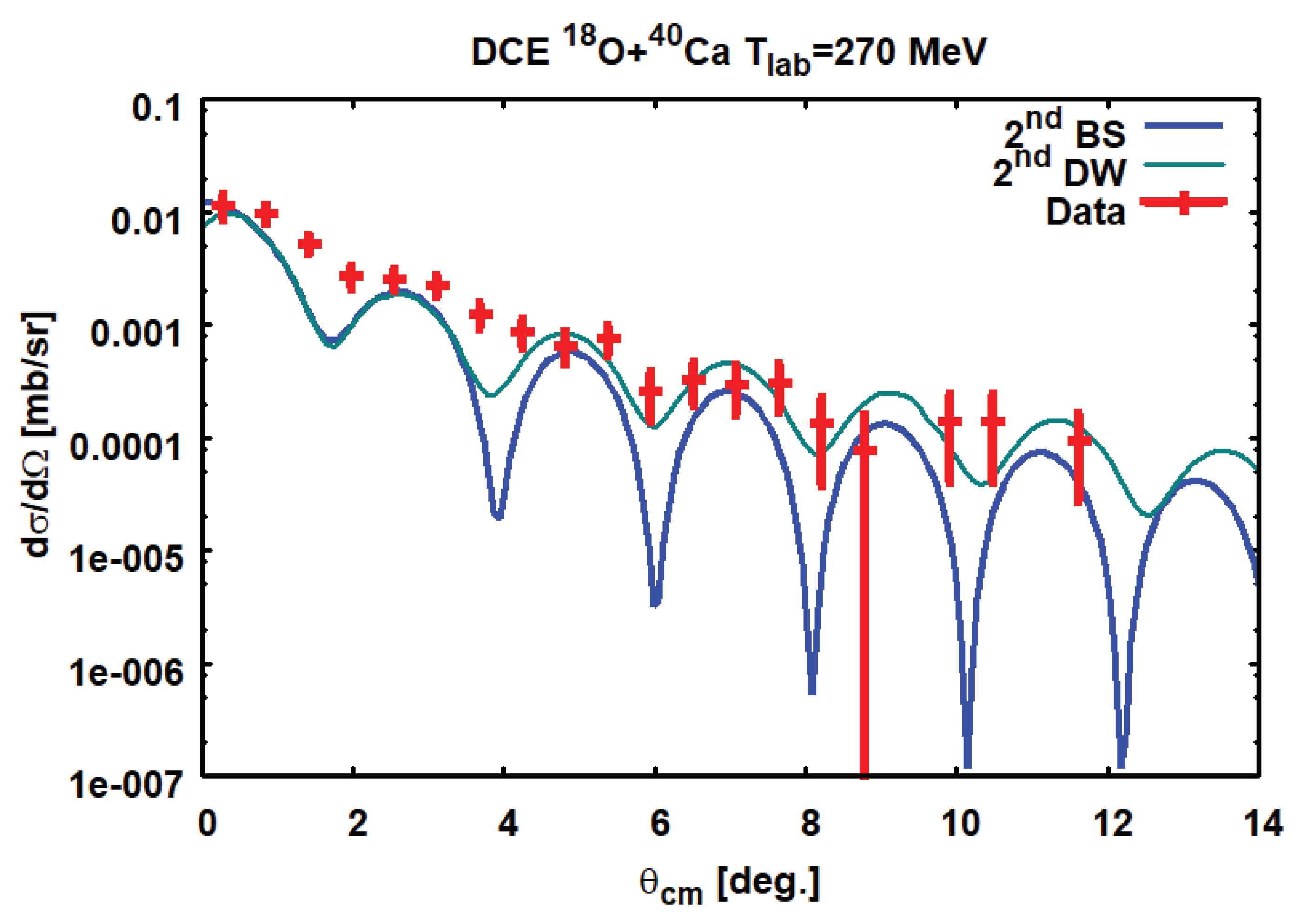
The nuclear DSCE transition form factors were constructed by the QRPA transition densities and response functions discussed in [4]. In Figure 4, the results obtained with the second order Black Sphere model are displayed and compared to the full second order DW results of [6] and the measured angular distribution. The angular range covered by the data corresponds to a remarkable range of momentum transfers up to about q α β 400 MeV/c.
As anticipated in Section 3.2, the terms containing the DW–distributions not only induce a strong suppression of the DSCE amplitude with respect to the plane wave limit but also imprint on DCE angular distributions their own diffraction structure caused by ISI and FSI. Thus, the diffraction pattern observed for heavy ion DCE cross sections is mainly determined by the optical model potentials and only to a lesser degree by the transition form factors. That effect was already discussed in [4] for SCE reactions, but in the DCE case the suppression is considerably enhanced. However, for a quantitative description DCE reactions, a full second order(or coupled channels) DW calculation is the method of choice as discussed in [2,6].
In view of the simplicity of the Black Sphere model the overall agreement between the two model calculations and to the data is remarkable. At forward angles, i.e. small momentum transfers, the two theoretical approaches give almost identical results. The deviations, developing with increasing scattering angles, indicate - as to be expected – the remaining differences of the schematic, semi–classical Black Sphere model to the quantal second order DW calculation. In [6] the latter were performed with about the same optical model potentials and nuclear structure input, but integrating numerically the optical model wave equations for partial waves up to 200 .

6. Summary

Starting from a fully microscopic and quantal approach to heavy ion DSCE reaction, the role of initial state (ISI) and final state (FSI) interactions and the induced rank–2 isotensor interaction were investigated. The DSCE amplitude, being of an in principle well known distorted wave two–step structure was reconsidered in an approach which allowed to separate ISI/FSI effects from nuclear matrix elements. ISI/FSI reaction dynamics led to a reaction kernel which was shown to be determined by the shape and size of the ion–ion optical potentials. Applications to data conformed the conjecture that ISI/FSI effects can be understood to a large extent already by the magnitudes of ion–ion total reaction cross sections.
The DSCE form factors and nuclear matrix elements were investigated in closure approximation. The detailed study of the interplay of nuclear structure and reaction dynamically effects led to the interesting result that the intermediate propagation induces correlations by imposing constraints on the DCE vertices and inducing an effective DSCE interaction. The DSCE interaction is obtained for the (tensorial) product of NN T–matrices with rank-0 central spin–scalar and spin–vector interactions and rank–2 spin–tensor interactions. The operator structure of the DSCE interaction was studied and transformed from the reaction theoretical t-channel formulation to the s–channel formalism required for nuclear structure studies and the derivation of nuclear matrix elements.
A briefly mentioned but highly interesting property of the DSCE mechanism or large research potential is that such DCE transitions are well suited to probe the little known rank–2 polarization tensors. They are generalizations of the polarization coefficients given by inversely energy sum rules like the nuclear dipole polarizability obtained from photo–absorption cross sections. The DSCE rank–2 nuclear polarization tensors occur also in 2 ν 2 β decay and have been studied experimentally and theoretically in nuclear double–gamma decay [7].
As closing remarks we emphasize that the presented approach is not meant to replace a full microscopic description of DCE reactions. Modern nuclear reaction and nuclear structure theory, as used e.g. in [6], provide the proper theoretical tools and numerical methods for the quantitative description of processes as complex as a DCE reaction. The purpose of the investigations presented in this article is to clarify the role of ISI/FSI dynamics and their interplay with residual ion–ion interaction in creating correlations and inducing effective isotensor interactions.
Here, we have studied those effects in the context of the DSCE scenario. Since the ISI/FSI effects and their influnence on nuclear matrix elements are of a general character, they are of relevance for any kind of peripheral heavy ion reactions used for spectroscopic studies.
Acknowledgments

H.L. acknowledges gratefully the support by DFG, grant Le439/16-2, and INFN/LNS Catania.

Appendix A. Auxiliary Energy and Residual Term for the Closure Approximation

In R e s ( ξ ) the residual terms beyond closure are collected. The next–to–leading–order term, i.e. the leading–order term in ξ is
R e s ( ξ ) = ω γ ω α ω γ T γ ( k γ ) + i η 2 ω γ ω α + ω γ + T γ ( k γ ) + i η 2 ξ + O ( ξ 2 )
which is already suppressed energetically by the quadratic energy denominators. The expectation value of ξ is
ξ = E 0 ( p , p | a A ) 1 ω γ E 1 ( p , p | a A ) ,
where
E n ( p , p | a A ) = c C E c + E C n b B | S N N ( p | 34 ) | c C c C | S N N ( p | 12 ) | a A
By closure we recover for n = 0 the DSCE–NME
E 0 ( p , p | a A ) = b B | S N N ( p | 34 ) S N N ( p | 12 ) | a A
and for n = 1 a sum of a new kind of rank–2 energy weighted sum rules defined for the transition from the parent nuclei to states in the daughter nuclei:
E 1 ( p , p | a A ) = c { a } E c b B | S N N ( p | 34 ) | c c | S N N ( p | 12 ) | a A + C { A } E C b B | S N N ( p | 34 ) | C C | S N N ( p | 12 ) | a A .
A closer look reveals that this corresponds to a sum of energy–weighted sum rules of products of spin–scalar, spin–vector, and spin–tensor in projectile and target is obtained.
As seen from Eq. (11), the sum rules include a momentum dependence from the plane wave factors and the (products of) V S T and V T n . However, that dependence is largely cancelled when defining the auxiliary energy by
ω γ E 1 ( p , p | a A ) E 0 ( p , p | a A ) | p = p = 0 ,
allowing to evaluate the ratio at vanishing momenta. By that choice, the NNLO term is cancelled and most likely the nigher order contributions will be minimized. Thus, the auxiliary energy is in fact a functional of the nuclei involved in the reaction and their (residual) interactions, ω γ = ω γ [ H a , H A ] .

Appendix B. The Second Order Reaction Kernel

With r α = r + x / 2 and r β = r x / 2 and interchanging momentum and radial integrations reaction kernel of Eq. (30) is rewritten as
K α β ( 2 ) ( P , q ) = d 3 r e i ( 2 P + q α β ) · r d 3 x e i q / 2 · x H ˜ S ( r + x / 2 ) H S ( r x / 2 ) d 3 k γ ( 2 π ) 3 g α γ ( + ) ( k γ ) e i k γ · x
The k γ –integral results in the coordinate propagator g α β ( x ) defined in Eq. (36). Thus,
K α β ( 2 ) ( P , q ) = d 3 r e i ( 2 P + q α β ) · r d 3 x e i 1 2 q · x H ˜ S ( r + x / 2 ) H S ( r x / 2 ) g α β ( x ) .
The form factor product is expanded into multipoles
H ˜ S ( r + x / 2 ) H S ( r x / 2 ) = 4 π m Y m ( r ^ ) Y m * ( x ^ ) H ( r , x )
with scalar form factors H ( r , x ) . By symmetry reasons, the odd multipoles are strongly suppressed and even vanish identically if the two absorption form factors are equal. Then, only even multipoles = 0 , 2 contribute. In practice, the expansion is dominated by far by the monopole component H 0 ( r , x ) . Doing so, the x–integral can be performed leading to
g 0 ( q | r ) = 0 d x x 2 g α β ( x ) j 0 ( 1 2 q x ) H 0 ( r , x ) .
Since g α β ( x ) is strongly peaked at x s i m x , we may replace H 0 ( r , x ) H 0 ( r , 0 ) as a further approximation, allowing to extract that form factor from the integral:
g 0 ( q | r ) H 0 ( r , 0 ) 0 d x x 2 g α β ( x ) j 0 ( 1 2 q x ) = H 0 ( r , 0 ) 1 4 π g α β ( + ) ( q )
Finally, to a good approximation we end up with
K α β ( 2 ) ( P , q ) 4 π 0 d r r 2 H 0 ( q | r , 0 ) j 0 ( | 2 P + q α β | r ) 1 4 π g α β ( + ) ( q ) ,
where a closer examination of the remaining integral reveals
4 π 0 d r r 2 H 0 ( r , 0 ) j 0 ( | 2 P + q α β | r ) = d 3 r e i ( 2 P + q α β ) · r H 0 ( r , 0 )
                    = 4 π d 3 r e i ( 2 P + q α β ) · r H ˜ S ( r ) H S ( r ) .
Hence, within the monopole approximation, we find the result:
K α β ( 2 ) ( P , q ) d 3 r e i ( 2 P + q α β ) · r H ˜ S ( r ) H S ( r ) g α β ( + ) ( q ) ,
as anticipated in Section 3.2.

Appendix C. Multipole Expansions of Spin-Scalar Operators

The multipoles of the spin–scalar operators are
R 0 ( p | i ) = 4 π L M Y L M * ( p ^ ) i L Y L M ( r ^ i ) j L ( p r i )
where Y L M is a rank–L spherical harmonic and j L ( x ) is a spherical Riccati–Bessel function.
Products of the spin–scalar operators result in the double–Fermi (FF) operators
R F F ( p , p | i j ) = ( 4 π ) 2 L 1 L 2 , L M ( ) M Y ( L 1 L 2 ) L M ( p ^ , p ^ ) R ( L 1 L 2 ) L M ( p p | i j )
given by the bi–spherical harmonics
Y ( L 1 L 2 ) L M ( x ^ , x ^ ) = M 1 M 2 ( L 1 M 1 L 2 M 2 | L M ) Y L 1 M 1 ( x ^ ) Y L 2 M 2 ( x ^ )
and with the spacial multipole operators
R ( L 1 L 2 ) L M ( p , p | i j ) = Y ( L 1 L 2 ) L M ( r ^ i , r ^ j ) j L 1 ( p r i ) j L 2 ( p r j )

Appendix D. Multipole Expansions of Spin-Vector Operators

Spin–operators are given conveniently in the basis defined by the set of bi–orthogonal spherical unit vectors { e μ , e μ * }
e ± 1 = ± 2 e x ± i e y ; e 0 = e z
and with the dual elements e μ * = ( ) μ e μ we obtain e μ * e ν = e μ e ν * = δ μ ν . Scalar products of two vector operators V 1 , 2 = μ V 1 , 2 μ e μ * are given by V 1 · V 2 = μ ( ) μ V 1 μ V 2 μ , while V 1 · V 2 = μ V 1 μ * V 2 μ .
Using σ = μ σ μ e μ * , the spin–vector operators are decomposed into spherical components by projection onto e μ
R μ ( p | i ) = R 1 ( p | i ) · e μ ; R 1 ( p | i ) = μ = 0 , ± 1 R μ ( p | i ) e μ * .
and the spin–vector operators become
R 1 ( p | i ) = 4 π L M L J M μ Y L M L * ( p ^ ) T ( L 1 ) J M ( p | i ) ( L M 1 μ | J M ) e μ * .
We have introduced the spin–orbital multipole operators ( S = 0 , 1 )
T ( L S ) J M ( p | i ) = i L Y L ( r ^ i ) [ σ i ] S J M j L ( p r i )
where
i L Y L ( r ^ ) [ σ ] S J M = M L M S ( L M L S M S | J M ) i L Y L M L ( r ^ ) [ σ M S ] S .
Obviously, that definition is in fact applicable for both S = 0 and S = 1 . The operators encountered in Σ G G , Σ T n T n , and the mixed Σ F T , and Σ G T , respectively, are constructed by essentially the above rules, which here were worked to for scalar products but are easily generalized to the case of higher rank tensor products.
The products of spin–vector operators appearing in the mixed Fermi-Gamow-Teller FG and FG operators
R G G ( p , p | i j ) = R 1 ( p , i ) · R 1 ( p , j )
require additional steps of recoupling before they are obtained finally as
R G G ( p , p | i j ) = ( 4 π ) 2 L M L 1 , L 2 , J 1 , J 2 ( ) L 1 + L 2 J 1 J ^ 1 J ^ 2 W ( L 1 J 1 L 2 J 2 ; 1 L ) × Y ( L 1 L 2 ) L M * ( p ^ , p ^ ) R L M ( L 1 L 2 , J 1 J 2 ) ( p p | i j )
where Y ( L 1 L 2 ) L M * = ( ) M Y ( L 1 L 2 ) L M . Reduced spin–orbital multipole operators were introduced:
R L M ( L 1 L 2 , J 1 J 2 ) ( p p | i j ) = T ( L 1 1 ) J 1 ( p | i ) T ( L 2 1 ) J 2 ( p | j ) L M = M 1 M 2 ( J 1 M 1 J 2 M 2 | L M ) T ( L 1 S ) J 1 M 1 ( p | i ) T ( L 2 S ) J 2 M 2 ( p | j )
W ( L 1 J 1 L 2 J 2 ; 1 L ) is a Racah coefficient.
The mixed products of spin–scalar and spin—vector operators acting as two–body operators in the same nucleus are found by the same recoupling techniques. Using σ = μ σ μ e μ we obtain
R F G , a b ( p , p ) = ( 4 π ) 2 μ e μ L 1 L 2 , L M L Y ( L 1 L 2 ) L M L * ( p ^ , p ^ ) × ( ) L 1 + L 2 L ( L 1 M 1 L 2 M 2 | L M L ) ( L 2 1 μ | J 2 N 2 ) ( L 1 M 1 J 2 N 2 | J M ) R J M , a b ( L 1 L 2 J 2 ) ( p p ) .
The reduced multipoles are
R J M , a b ( L 1 L 2 J 2 ) ( p p ) = ( 13 ) T ( L 1 0 ) L 1 ( p | 1 ) T ( L 2 1 ) J 2 ( p | 3 ) J M .
With ( L 2 M 2 1 μ | J 2 N 2 ) = J ^ 2 3 ( ) J 2 1 + N 2 + μ ( L 2 M 2 J 2 N 2 | 1 μ ) the summation over N 2 can be perform
N 2 ( ) N 2 ( L 1 M 1 J 2 N 2 | J M ) ( L 2 J 2 N 2 | 1 μ ) ( L 1 M 1 L 2 M 2 | L M L ) = ( ) L 2 + J L J ^ 3 W ( L 1 J L 2 1 ; J 2 L ) ( J M 1 μ | L M L )
and ( J M 1 μ | L M L ) = ( ) 1 + M L + L μ L ^ 3 ( J M L M L | 1 μ ) . Collecting phases and pre–factors, the final result is:
R F G , a b ( p , p ) = ( 4 π ) 2 L 1 L 2 J 2 , L M L , J M Y ( L 1 L 2 ) L M L * ( p ^ , p ^ ) × ( ) L 1 L + J J 2 + M L J ^ J ^ 2 L ^ 3 W ( L 1 J L 2 1 ; J 2 L ) R J M , a b ( L 1 L 2 J 2 ) ( p p ) μ ( J M L M L | 1 μ ) e μ .
The the elements R G F , a b , R F G , A B , and R F G , B A are obtained by the same approach.

Appendix E. Recoupling of Bi-Spherical Harmonics

An important property of the bi–spherical harmonics is that for x ^ = x ^ they reduce to ordinary spherical harmonics:
Y ( L 1 L 2 ) L M ( x ^ , x ^ ) = A L 1 L 2 L Y L M ( x ^ )
with
A L 1 L 2 L = L ^ 1 L ^ 2 4 π L ^ ( L 1 0 L 2 0 | L 0 )
The Clebsch–Gordan coefficient vanishes if L 1 + L 2 + L = 2 n + 1 is an odd number.
The evaluation of the DSCE–NME leads to products of two bi-spherical harmonics in the momenta p and p . By further steps of recoupling, the resulting product of four ordinary spherical harmonics can be reduced to a product of two spherical harmonics of the same argument, forming finally a single bi–spherical harmonic.
Y ( L 1 L 2 ) L M ( p ^ , p ^ ) Y ( L 3 L 4 ) L M ( p ^ , p ^ ) = λ μ A L 1 L 3 A L 2 L 4 Y λ μ ( p ^ , p ^ ) λ μ ( L M L M | λ μ ) M 1 M 2 M 3 M 4 m m × ( L 1 M 1 L 2 M 2 | L M ) ( L 3 M 3 L 4 M 4 | L M ) ( L 1 M 1 L 3 M 3 | m ) × ( L 2 M 2 L 4 M 4 | m ) ( L M L M | λ μ ) ( m m | λ μ )
which results in 9-j symbol:
Y ( L 1 L 2 ) L M ( p ^ , p ^ ) Y ( L 3 L 4 ) L M ( p ^ , p ^ ) = λ μ Y ( ) λ μ ( p ^ , p ^ ) ( L M L M | λ μ ) A L 1 L 3 A L 2 L 4 ^ ^ L ^ L ^ L 1 L 2 L L 3 L 4 L λ
Defining
Γ L 3 L 4 L L 1 L 2 L ( λ ) = 1 4 π L ^ 1 L ^ 2 L ^ 3 L ^ 4 L ^ L ^ L 1 L 2 L L 3 L 4 L λ
we obtain
Y ( L 1 L 2 ) L M ( p ^ , p ^ ) Y ( L 3 L 4 ) L M ( p ^ , p ^ ) = λ μ Γ L 3 L 4 L L 1 L 2 L ( λ ) ( L M L M | λ μ ) Y ( ) λ μ ( p ^ , p ^ ) ,
and find
Y ( L 1 L 2 ) L ( p ^ , p ^ ) Y ( L 3 L 4 ) L ( p ^ , p ^ ) λ μ = Γ L 3 L 4 L L 1 L 2 L ( λ ) Y ( ) λ μ ( p ^ , p ^ ) .
The bi-spherical harmonics form an over–complete system, but there is an orthogonality relation:
d p ^ d p ^ Y ( L 1 L 2 ) λ μ * ( p ^ , p ^ ) Y ( L 3 L 4 ) λ μ ( p ^ , p ^ ) = M 1 M 2 ( L 1 M 1 L 2 M 2 | λ μ ) ( L 1 M 1 L 2 M 2 | λ μ ) = δ λ λ δ μ μ

References

  1. Lenske, H.; Cappuzzello, F.; Cavallaro, M.; Colonna, M. Heavy Ion Charge Exchange Reactions and Beta Decay. Prog. Part. Nucl. Phys. 2019, 109, 103716. [Google Scholar] [CrossRef]
  2. Cappuzzello, F.; others. Shedding light on nuclear aspects of neutrinoless double beta decay by heavy-ion double charge exchange reactions. Prog. Part. Nucl. Phys. 2023, 128, 103999. [Google Scholar] [CrossRef]
  3. Cappuzzello, F.; others. The NUMEN Technical Design Report. Int. J. Mod. Phys. A 2021, 36, 2130018. [Google Scholar] [CrossRef]
  4. Lenske, H.; Bellone, J.I.; Colonna, M.; Lay, J.A. Theory of Single Charge Exchange Heavy Ion Reactions. Phys. Rev. 2018, C98, 044620. [Google Scholar] [CrossRef]
  5. Lenske, H. Theory and applications of nuclear direct reactions. Int. J. Mod. Phys. E 2021, 30, 2130010. [Google Scholar] [CrossRef]
  6. Bellone, J.I.; Burrello, S.; Colonna, M.; Lay, J.A.; Lenske, H. Two-step description of heavy ion double charge exchange reactions. Phys. Lett. B 2020, 807, 135528. [Google Scholar] [CrossRef]
  7. Soederstroem, P.A.; Capponi, L.; Aciksoz, L.; Otsuka, T.; Tsoneva, N.; Tsunoda, Y.; Balabanski, D.L.; Pietralla, N.; Guardo, G.L.; Lattuada, D.; Lenske, H.; Matei, C.; Nichita, D.; Pappalardo, A.; Petruse, T. Electromagnetic character of the competitive γγ/γ-decay from 137mBa. Nature Commun. 2020, 11, 3242. [Google Scholar] [CrossRef] [PubMed]
  8. Lenske, H.; Bellone, J.; Colonna, M.; Gambacurta, D. Nuclear Matrix Elements for Heavy Ion Sequential Double Charge Exchange Reactions. Universe 2021, 7, 98. [Google Scholar] [CrossRef]
  9. Cappuzzello, F.; Cavallaro, M.; Agodi, C.; Bondi, M.; Carbone, D.; Cunsolo, A.; Foti, A. Heavy ion double charge exchange reactions: A tool toward 0νββ nuclear matrix elements. Eur. Phys. J. 2015, A51, 145. [Google Scholar] [CrossRef]
  10. Franey, M.A.; Love, W.G. Nucleon nucleon t matrix interaction for scattering at intermediate-energies. Phys. Rev. 1985, C31, 488–498. [Google Scholar] [CrossRef] [PubMed]
  11. Ejiri, H.; Suhonen, J.; Zuber, K. Neutrino-nuclear responses for astro-neutrinos, singe beta decays and double beta decays. Phys. Rept. 2019, 797, 1–102. [Google Scholar] [CrossRef]
1
The factor 1 8 is due to the extraction of the factor 2 from the delta–distribution, defined in 3–D momentum space.
Figure 1. Schematic representation of the collisional processes contributing to a DCE reaction A ( Z , N ) B ( Z ± 2 , N 2 ) . The DSCE reaction scenario of second–order in the isovector NN T–matrix (left) competes with the direct MDCE mechanism proceeding by an isotensor interaction induced by off–shell pion–nucleon DCE scattering.
Preprints 95494 g001
Figure 2. The DSCE ladder and the so–called Z-graph entering into the retarded DSCE propagator.
Preprints 95494 g002
Figure 4. Second order Black Sphere (2ndBS, bold blue line) results for the reaction   40 Ca ( 18 O , 18 Ne ) 40 Ar at T l a b = 270 MeV are compared to data [9] and the full second order DW results of Ref. [6] (2ndDW, grey thin line). The BS results are normalized to the DW results by a χ 2 –fit.
Preprints 95494 g004
Disclaimer/Publisher’s Note: The statements, opinions and data contained in all publications are solely those of the individual author(s) and contributor(s) and not of MDPI and/or the editor(s). MDPI and/or the editor(s) disclaim responsibility for any injury to people or property resulting from any ideas, methods, instructions or products referred to in the content.
Copyright: This open access article is published under a Creative Commons CC BY 4.0 license, which permit the free download, distribution, and reuse, provided that the author and preprint are cited in any reuse.
Prerpints.org logo

Preprints.org is a free preprint server supported by MDPI in Basel, Switzerland.

Subscribe

© 2024 MDPI (Basel, Switzerland) unless otherwise stated