Preprint
Article

Design and Implementation of a Smart Photovoltaic Hydroponic Greenhouse for Sustainable Agriculture in Tunisia

Altmetrics

Downloads

239

Views

148

Comments

0

Submitted:

08 January 2024

Posted:

09 January 2024

You are already at the latest version

Alerts
Abstract
Sustainable agriculture has become increasingly important in Tunisia due to the drought that has been affecting the country's climate in recent years. This has become a major threat to the economy, making it necessary to explore alternative methods of agriculture that are more sustainable. Moreover, smart hydroponic cultivation based on renewable energies has become increasingly widespread, promoting the quality and efficiency of agricultural production despite weather parameters variations and global warming. This work aims to create a sustainable agriculture system in Tunisia through the design and implementation of a smart photovoltaic (PV) hydroponic greenhouse. The greenhouse will utilize advanced technology to optimize plant growth and reduce water usage, while also incorporating solar panels to generate renewable energy. The end goal is to create a self-sufficient and eco-friendly agricultural system that can provide fresh produce to local communities year-round. In this work, we are interested to the automation of the hydroponic greenhouse (HG)’s thermal conditioning system based on an asynchronous motor pump and powered by a PV generator. In the first stage, we analyzed the mathematical modeling of a stand-alone PV-HG system that consists of a PV generator, a three-phase inverter, an asynchronous motor pump, and a hydroponic system. After that, we developed a Field Oriented Control based on proportional integral (PI) regulators to adjust the rotation speed of the asynchronous motor pump, which aimed to provide the cooling and heating needs of the plant. The simulation results demonstrated the effectiveness of the proposed system . Additionally, we designed and implemented a smart system based on the internet of things (IoT) to enable remote control of internal and external parameters of the HG. This intelligent solution utilizes sensors, microcontrollers, and other devices and ensures the monitoring and the maintaining of the ideal growing conditions for our plants, guaranteeing that they receive the proper amount of temperature, humidity, and lighting. This type of system can be an invaluable tool for maximizing yields and achieving optimal results. With the right approach and attention to detail, we can create a sustainable and efficient growing environment that will help our plants flourish year-round.
Keywords: 
Subject: Environmental and Earth Sciences  -   Sustainable Science and Technology

1. Introduction

Food security is a prerequisite for the well-being and progress of the population. According to the International Renewable Energy Agency, there is an urgent need to increase food production by 60% and increase water availability by 55% by 2030 [1]. This increased demand depends primarily on agriculture, which represents one of humanity's oldest occupations and endeavors, with a variety of influences that include natural resources, economic interactions, energy needs, and public health. Greenhouses are proving to be a promising alternative to meet these increasing demands as they have the potential to meet both energy and food production needs [2]. Ensuring the environmental sustainability of agricultural systems represents a major challenge for nations, especially given the need to adapt to climate change and mitigate its impacts on agriculture [3,4,5]. Given that the agricultural sector is highly energy dependent, sustainable agriculture has become imperative to address current environmental issues and adapt to the energy transition.
The effectiveness of agricultural production depends on a variety of environmental factors. These include elements that influence photosynthesis, such as light intensity, atmospheric CO2 concentration, water supply, and mineral content. Climatic conditions, particularly temperature and precipitation, are also essential factors [6,7]. In addition, the quality of the soil, including the presence of ions, water circulation, and oxygenation of roots, has a significant impact on agricultural success [8]. Even the presence of a deficiency in one of these factors can limit plant production, irrespective of variations in other factors [9]. This leads to considerations about the feasibility of controlling environmental factors [10].
Therefore, sustainability and efficient energy management have become a topic of great interest in various sectors, including transportation, industry, and agriculture. An effective strategy to mitigate future global warming is to reduce dependence on fossil fuels through the use of alternative energy sources [11]. The key to achieving sustainability and reducing carbon emissions lies in improving energy efficiency in all sectors and transitioning from traditional energy sources to renewable energy sources (REs) [12,13]. Recently, renewable energy technologies such as solar energy, geothermal energy [14,15,16] biomass [17,18,19], wind energy [20], hydrogen [21] and photovoltaic energy [22,23,24] have gained global attention as new alternatives to electricity generation for conditioning agricultural greenhouses. The share of renewable energy in electricity generation is expected to increase from less than 27% in 2019 to 30% in 2050 [25,26]. Farms that use renewable energy sources offer numerous benefits, including improved energy self-sufficiency, income diversification, and improved resilience to climate change [27,28]. In recent years there has been a growing interest in exploring soilless technologies, particularly in greenhouses, where the use of renewable energy offers significant prospects for reducing energy [29]. In this context, solar energy greenhouse represents an alternative to traditional agricultural systems [30,31,32,33,34]. Likewise, photovoltaic hydroponic systems offer a unique range of benefits including significantly reduced water consumption, improved health outcomes through minimal pesticide use, high crop yields, and rapid plant growth [35,36,37].
Moreover, it's fascinating to see how the concept of smart farming is catching the attention of farmers, agriculturists, and researchers alike. One of the prominent approaches to smart farming is the use of smart greenhouse farming, which is an enclosed cultivation process that leverages information and communication technology to improve the quality and quantity of crops with minimal human intervention. With the advent of IoT technology, there is a vast potential for innovative methods and smart solution development that can revolutionize the agriculture sector. Therefore, integrating the Internet of Things (IoT) with a greenhouse can transform it into a smart and automated greenhouse, which is considered to be one of the ideal solutions. By doing so, IoT-enabled greenhouses can address various challenges and assist growers in enhancing the productivity of food and crops [38]. Numerous scientific investigations have been conducted to advance the application of smart technologies within agricultural practices, particularly in hydroponic greenhouses. An illustrative case is the study by Sadek and al. [39], in which they developed a smart hydroponic and aeroponic system that included advanced sensors and devices for monitoring various meteorological parameters both inside and outside the agricultural greenhouse. This innovative system enables automated regulation of internal environmental conditions, tailored to specific plant species and seasonal requirements. The results led to an 80% reduction in water and energy consumption and a remarkable shortening of the growth period by 45 days compared to 75 days with the traditional system. Sudana et al. [40] developed a circulation-free drip hydroponic system using IoT technology for pepper plants, which are among the most vitamin-rich vegetables and provide an excellent opportunity for local and export markets. However, due to its susceptibility to temperature and nutrient fluctuations, this plant requires intensive treatment. On the other hand, evaporation from the plants also decreases within the greenhouse, and therefore the pepper rots, especially in the rainy season. Therefore, the solution proposed in this work is an effective way to reduce risks and we have seen that thanks to this approach we have been able to minimize plant degradation and contribute to the preservation of nutrient solutions. Then, smart and remotely connected agricultural greenhouses emerged with a sustainable development architecture such as the prototype of Fernandes et al. [41], who developed a connected hydroponic system that allows users to remotely monitor and control plant growth and environmental conditions. The results of the work carried out made it possible to implement optimal control strategies to reduce costs while increasing crop growth. With the same goal, Chaiwongsai [42] was interested in developing a hydroponic system in a tropical climate that can automatically control the factors suitable for different vegetables in different nutrient solution tanks using IoT to monitor crop condition, water levels, and others control pH value. Al-Naemi and Al-Otoom [43] are developing a smart, sustainable greenhouse model powered by solar energy, advanced control systems, and efficient water management, with significant benefits including reduced water consumption, profitable vegetable farming, and significant potential to improve food security in the Gulf Countries Council (GCC) countries. The economic analysis for commercial implementation revealed an attractive investment with a return on investment of 340% and a payout period of 5 years. The study by Andrianto et al. [44] focuses on developing IoT-based smart greenhouses for pesticide-free hydroponic cultivation using an Arduino Mega2560 controller to monitor and control various environmental parameters. The system enables remote monitoring and control via a smartphone application, ensuring efficient and pesticide-free plant growth.
In Tunisia, photovoltaic hydroponic systems can significantly contribute to the development of sustainable agriculture due to sufficient solar resources and an ever-growing policy approach to promoting renewable energy and fighting global warming. To this end, the photovoltaic hydroponic system installed at the site of Borj Cedria-Tunis, developed by Bouadila et al. [45,46] constitutes a prototype aimed at improving the production and use of PV energy in agricultural systems. In addition, this energy is then transmitted to the electricity network, which will help to increase the penetration rate of renewable energy in the distribution network. This flexibility allows for optimal energy management and ensures that the system can operate even in the event of a power outage. The system has two operating modes: ON-GRID and OFF-GRID. In ON-GRID mode, the air conditioner is powered directly from the grid. In OFF-GRID mode, however, the air conditioning system is powered by the PV source. The main aim of this work is to analyze and experiment with the standalone PV conditioning system of the hydroponic greenhouse. The focus is on modeling and control to ensure optimal performance and efficiency. Through experimental studies, we hope to gain valuable insights into the behavior of the system and identify opportunities for improvement. The work is divided into four main parts. The first part focuses on the mathematical modeling of the various components of the system. The second part deals with the development of control laws to optimize system performance. A numerical simulation using Simulink is also presented to demonstrate the effectiveness of the proposed study. The fourth part of the article focuses on the experimental implementation of a smart solution based on an IoT-based solution to remotely control the internal and external parameters of the hydroponic PV system. This solution uses sensors, microcontrollers, and other devices to monitor and maintain the ideal growing conditions for the plants.

2. Materials and Methods

2.1. Description of the PV Hydroponic Greenhouse (PV-HG)

The studied PV Hydroponic greenhouse (PV-HG) developed by Bouadila et al. [45,46] as shown in Figure 1, includes all the essential components to ensure an ideal growth environment.
To meet the energy needs of the hydroponic greenhouse, a custom-designed hybrid PV system, as shown in Figure 1, was sized based on the peak power requirement, which was 2.1 kWp. This system includes solar cell modules, solar charge controllers, inverters and protection devices. In the event of possible overproduction, batteries are installed to store energy. This PV/battery hybrid setup includes six 350Wc solar cell modules, a 30A solar charge controller, and a 24V/500VA off-grid inverter. To facilitate energy storage, four 12V/200AH solar batteries are integrated, accompanied by a battery protection unit and a DC protection box with pre-wired MC4 connectors. It is complemented by a data acquisition and control system installed in the greenhouse. This system records various parameters, including climate, electrical, and energy data, and manages actuators (Figure 1 (d)) to regulate indoor climate and crop conditions. It allows control of air temperature, airflow, water temperature, water circulation, and lighting, adjusting these parameters depending on plant requirements. The actors responsible for these functions are listed in Table 1.
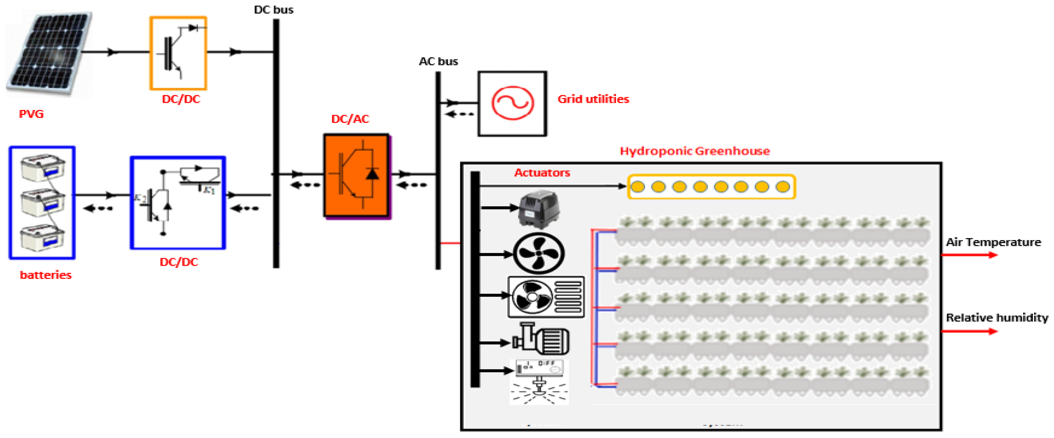
The hydroponic greenhouse is a thermally insulated structure with a surface area of 24 m2 and a height of 3 m, facing southeast. It features a galvanized steel structure covered with polyurethane sandwich panels for insulation. The greenhouse consists of two different rooms: a growth room with glazed sides on the north and south facades and fixed or removable screens to control light and sunlight. The second room is dedicated to the germination of various plants and is ventilated by an electric aerator. The greenhouse is equipped with an irrigation and water collection system that optimizes water and nutrient supply, promoting plant growth and metabolism. Additionally, the soilless growing system includes a ventilation system with three fans, one on the south side and two on the north side, to improve air quality, as well as a lighting system to compensate for the limited winter sun. Figure 2 describes this system’s synoptic diagram.
The system integrates two DC-DC converters dedicated respectively to tracking the maximum power point of the PV generator and regulating the DC voltage. A three-phase inverter connected to the network via an RL filter ensures DC-AC conversion. The hydroponic system represents a local load connected to the network by an AC bus.
The system can operate in two scenarios. The first scenario is ON-GRID where the hydroponic system is powered directly by the grid. The second scenario is OFF-GRID where the system is considered as a stand-alone PV installation and the hydroponic load is powered by the PV source through the inverter.

2.2. Modeling of the Stand-alone PV-HG

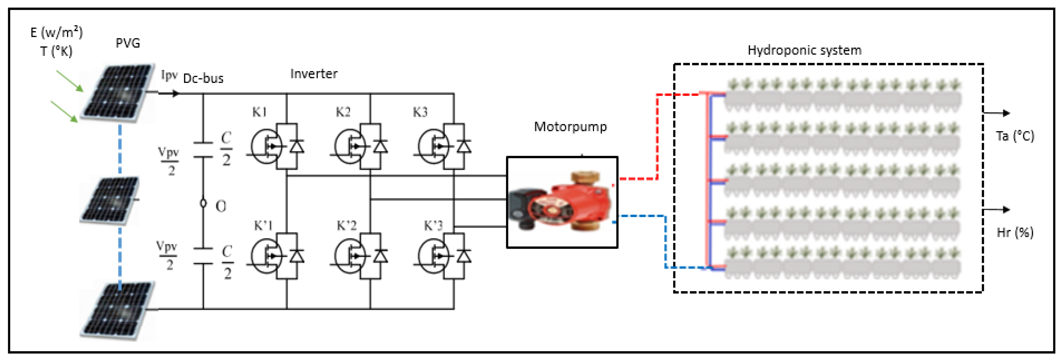
In this work, we are interested in the OFF-GRID mode of the stand-alone PV hydroponic system powered by the PV source. This system is described as shown in Figure 3. The conditioning system described in the article is designed to meet the heating and cooling needs of the plant depending on the season and climatic conditions. It utilizes an asynchronous motor pump to ensure hot water in the winter season and cold water in the summer season, ensuring that the plant is provided with a climate that meets its needs.

2.2.1. Modeling of the PV source

The mathematical model of the Photovoltaic Generator (PVG) is illustrated by equations (1) and (2) [53]:
I p v = N p I p h N p I s s e x p V p v + R S I p v / N s V T 1  
V T = n K B T / q
where:
-
Ipv (A) and Vpv (V) are respectively the PV current and the PV voltage,
-
Iph (A) is the light generated current,
-
Rs (Ω) and Rsh (Ω) are respectively PV arrays series and shunt resistances,
-
A is the ideality factor of the PV panel, K is the Boltzmann constant, T (°K) is the temperature cell, q is the electronic charge and VT (V) is the thermodynamic potential of the PV cell.
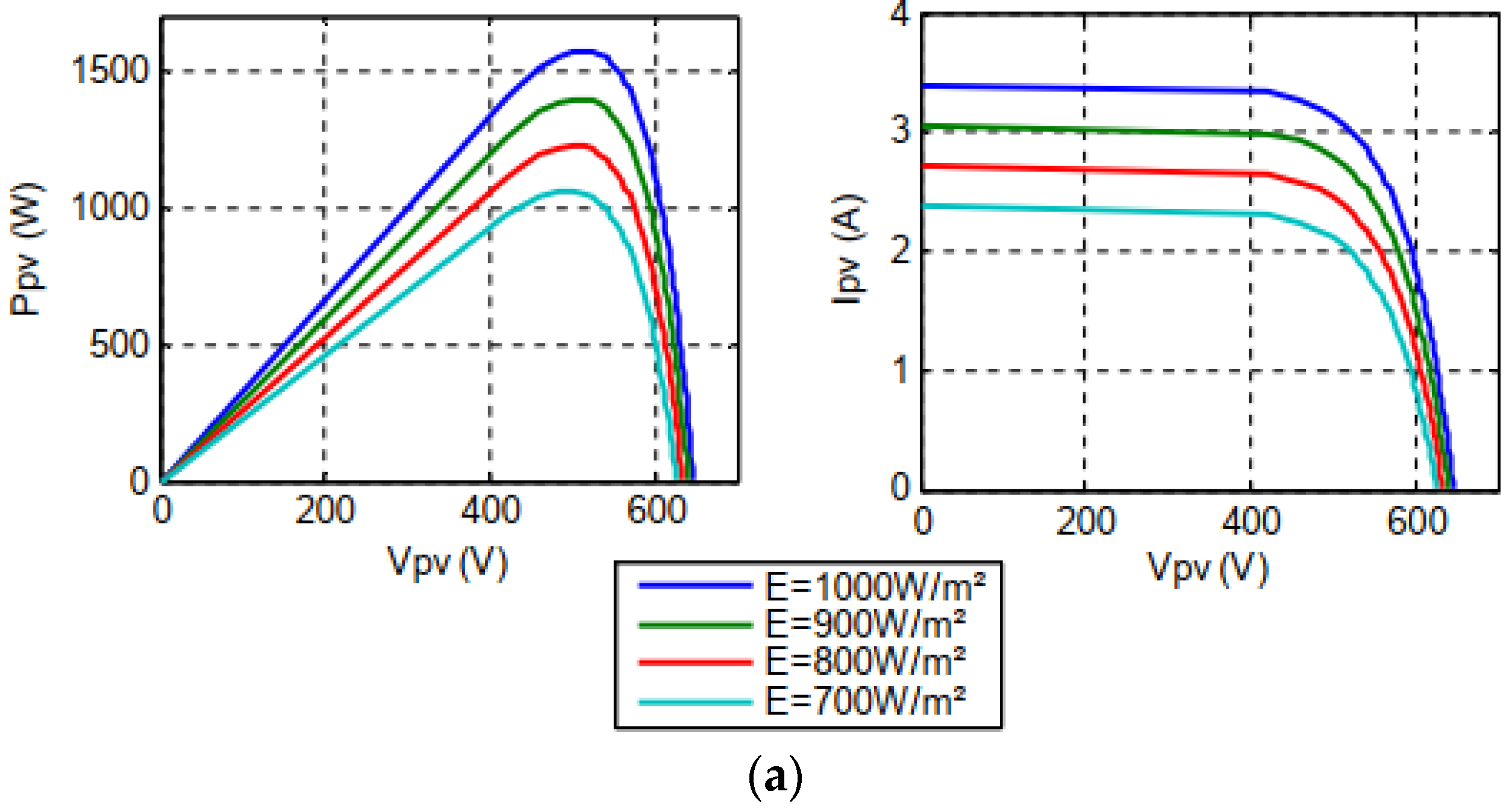
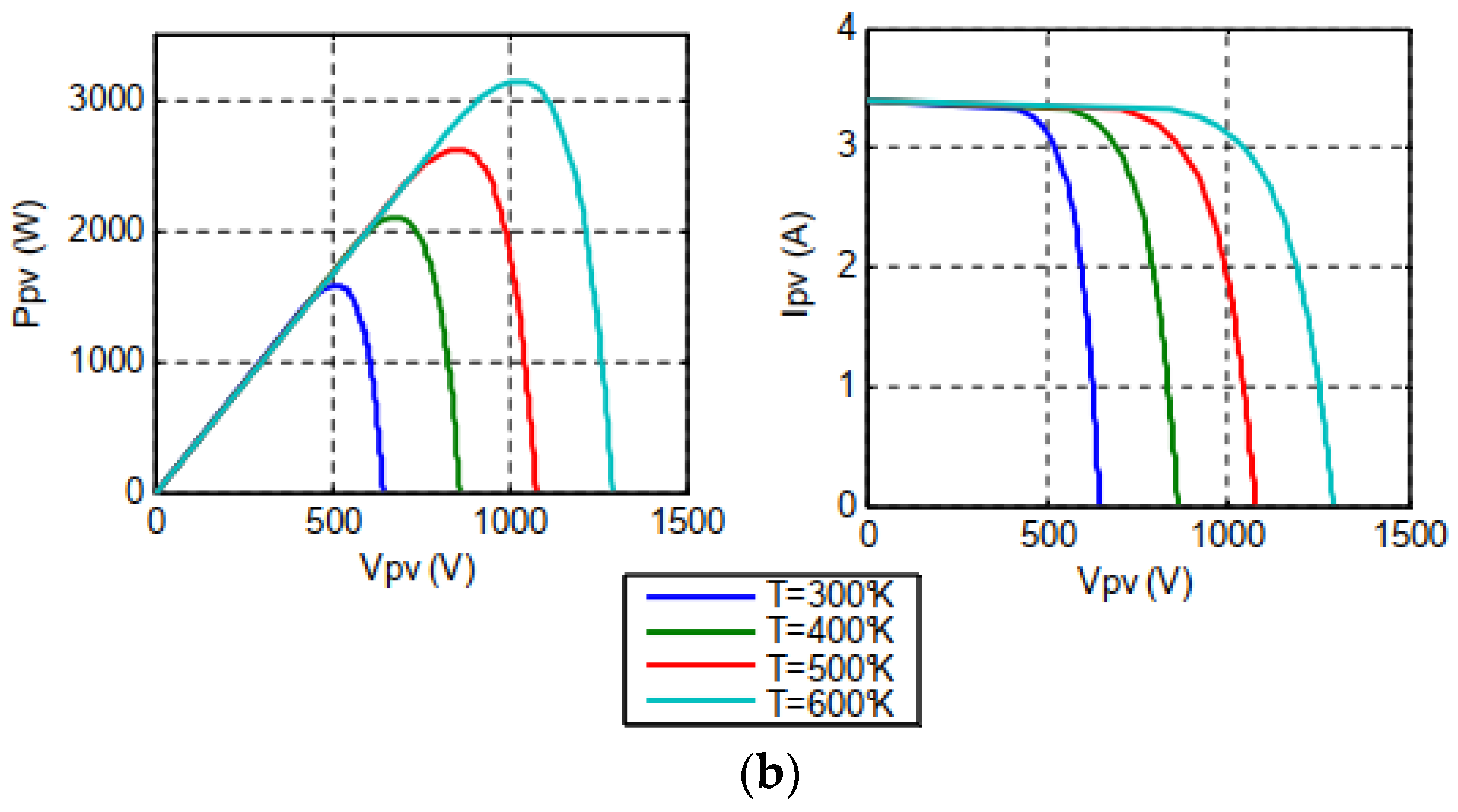
The simulation results presented in Figure 4 demonstrate how changes in solar irradiation (a) and temperature (b) affect the characteristic curves of the PV generator.
The performance of a PVG is affected by changes in solar irradiation and temperature, which can cause variations in the output voltage and current. Therefore, it is important to analyze the behavior of a PVG under different environmental conditions to optimize its performance and ensure the efficient operation of the greenhouse. By understanding the impact of these factors on the PVG, we can design a system that is better equipped to handle weather changes and ensure consistent energy production.

2.2.2. Modeling of the DC-bus

To maintain an energy balance between the power generated by the PVG and the power alimenting the motor pump by charging or discharging the capacitor, it is crucial to use a DC-bus. Equation (3) gives the expression of the DC-bus current [54].
I c = C d V d c / d t
where Ic (A) and Vdc (V) are respectively the DC-bus current, and voltage and C is the capacity value.

2.2.3. Modeling of the three-phase inverter

The DC energy generated by the PVG is converted into AC energy using a three-phase inverter, which is then used to power the asynchronous motor pump. The simple modulated voltages which are the output voltages of the inverter (Vs1, Vs2, Vs3) are expressed by (4), where (K1, K2, K3) are the switches control signals of the inverter [55].
V S 1 V S 2 V S 3 = V d c 3 2 1 1 1 2 1 1 1 2 K 1 K 2 K 3

2.2.4. Modeling of the asynchronous motor pump

The mathematic model of the asynchronous motor in the dq-Park referential is given by (5) and (6) [50].
I d s = 1 r s + σ L s s V d s M L r s Φ d r + ω s L r M Φ q r + ω s σ L s I q s I q s = 1 r s + σ L s s V q s M L r s Φ q r ω s L r M Φ d r ω s σ L s I d s Φ d r = 1 T r s + 1 T r ω s ω m Φ q r + M I d s Φ q r = 1 T r s + 1 T r ω s ω m Φ d r + M I q s
d ω m d t = P ² M J L r Φ d r I q s Φ q r I d s P J C r
where:
-
I d s   and I q s are respectively the d and q stator currents,
-
V q s and V q s are respectively the d and q stator voltage,
-
Φ d r and Φ q r are respectively the d and q rotor flux,
-
ω s and ω r   are respectively the stator and rotor electrical speed,
-
Rs and Rr are respectively the stator and rotor resistance,
-
L s and L r are respectively the stator and rotor inductance,
-
σ is a constant depending on motor parameters, M is the mutual inductance,
-
J is the rotor inertia moment, P is the number of poles pairs.
The hydrodynamic load torque C r of the pump is given by (7) where A p is the torque constant as in [49].
C r = A p ω r 2
The model of the centrifugal pump is described by similarity’s lows such as in (8)
Q = N N Q       H = N N 2 H
Where:
-
N et N’ are the real and nominal pump speeds,
-
Q et Q’ are the real and nominal water flow,
-
H et H’ are the real and nominal pump heights.

2.2.5. Modeling of the Hydroponic Greenhouse

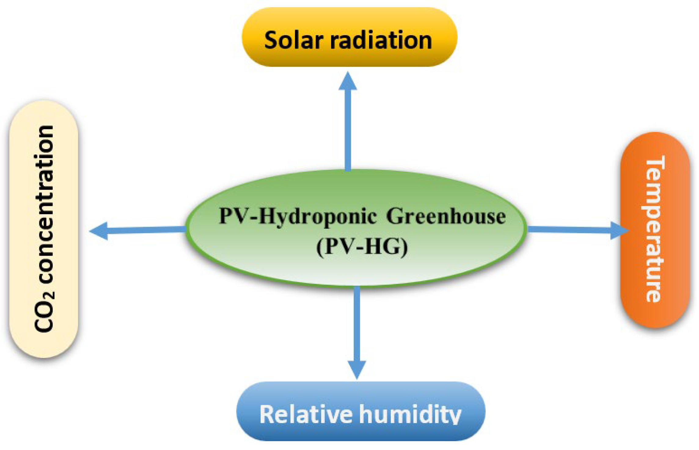
The hydroponic greenhouse thermal equilibrium model developed to describe the internal microclimate, simplified by neglecting several physical phenomena: radiative heat exchange between walls and roofs; the storage capacity of sandwich panel walls and the roof; the absorptive capacity and heat capacity of the enclosed air; and conductive heat exchange between the interior air, sandwich panel walls and the roof. The four main parameters for heat exchange into the greenhouse are temperature, humidity, solar radiation, and CO2. In this model we will ignore the effect of CO2 (Figure 5).
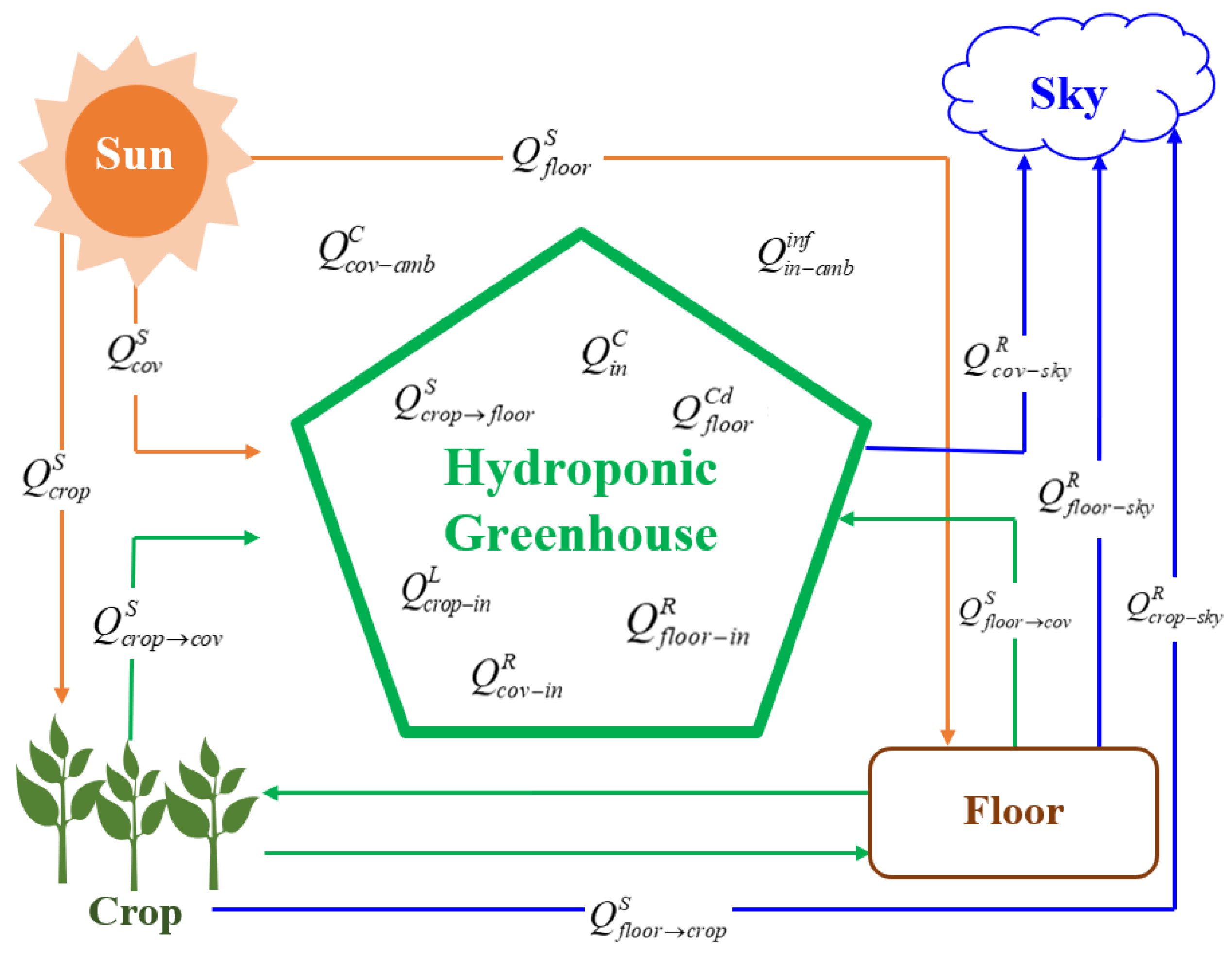
This model consists of four components: the single-wall cover, the internal air, canopy and the protected floor as in Figure 6.
where
Q c o v s , Q c r o p c o v s , Q f l o o r c o v s , Q c r o p s , Q f l o o r c r o p s a n d Q f l o o r s are the absorbed heat of solar energy in all greenhouse components.
Q c o v a m b C a n d Q i n C are the convective heat outside and inside the greenhouse.
Q f l o o r C d is the heat exchanged by conduction from the floor.
Q i n a m b i n f is the heat losses by infiltration.
Q c r o p i n L the heat exchanged by evapotranspiration of the crop.
Q c o v s k y R , Q c o v i n R , Q c r o p i n R , Q c r o p s k y R , Q f l o o r i n R a n d Q f l o o r s k y R are the heat losses due to radiation from the greenhouses and their surroundings.
Each of these elements is defined by a state variable, namely the temperature, which is assumed to be uniform across their cover and protected floor surfaces. The indoor air is also characterized by a uniform absolute humidity throughout the entire greenhouse volume. To address this problem, four balances are created for the indoor air of the greenhouse [51]. The heat balance at the cover is given by (9):
d T cov d t = 1 d a i r C p A c o v Q c o v S + Q c r o p c o v S + Q f l o o r c o v S Q c o v a m b C Q i n C + Q c o v s k y R + Q c o v i n R
where:
-
T c o v : coverture temperature - d a i r : air density - C p : specific heat of air at constant pressure - A c o v : surface area of the coverture
The calculation of the crop's energy balance involves the utilization of (10):
d T c r o p d t = 1 d a i r C p A c r o p Q c r o p S + Q f l o o r c r o p S Q c r o p i n R Q c r o p s k y R Q c r o p i n L
where:
-
T c r o p   : crop temperature - A c r o p : surface area of the crop
The calculation of the energy balance at the greenhouse floor is performed by employing (11):
d T f l o o r d t = 1 d a i r C p A f l o o r Q f l o o r S Q f l o o r C d Q f l o o r i n R Q f l o o r s k y R
where:
-
T f l o o r : floor temperature - A f l o o r : surface area of the floor
The dynamical equation describing the thermal evolution of the internal air is computed using (12):
d T i n d t = 1 d a C a V Q i n C Q c o v i n R Q c r o p i n R Q i n a m b i n f
where:
-
T i n : crop temperature - V: volume of the greenhouse.

2.3. Control of the PV-HG system

2.3.1. Field oriented control applied to the Asynchronous conditioning motor pump

Field Oriented Control (FOC) is a method used to control the asynchronous machine as an independent excited direct current machine. This method takes advantage of the natural decoupling between the rotor's and stator's current, which allows for a very rapid torque response. Additionally, FOC eliminates the influence of rotor leakage reactance and stator, resulting in better outcomes compared to methods based on the orientation of the stator flux or the air gap flux [52].
In this work, the indirect FOC method was chosen where the Park angle is calculated from the stator pulsation. The pulsation is reconstituted using the speed of the machine and its rotor to control the stator current and subsequently fix its operating point.
The FOC is based on the orientation of the Park (d,q) referential such that the q axis component of the rotor flux is zero as in (13).
Φ d r = Φ r Φ q r = 0
Therefore, the model of the control is given by (14):
V d s = R s I d s + σ L s d I d s d t ω s σ L s I q s V q s = R s I q s + σ L s d I q s d t + ω s σ L s I d s Φ r = M I d s ω s = ω r + M I q s T r Φ r
The electromagnetic torque is expressed by (15).
C e m = 3 p M / 2 L r Φ r I q r
(a) 
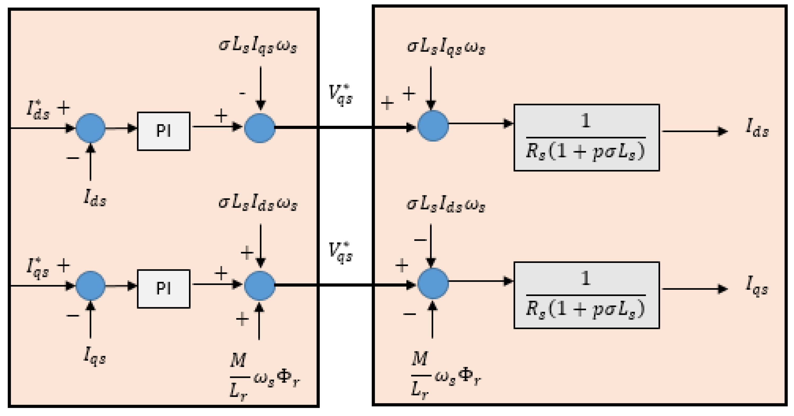
Decoupling: It is interesting to add decoupling terms to make the d and q axes completely independent. Above all, this decoupling makes it possible to easily write the equations of the machine and the control part and thus calculate the coefficients of the speed and current controllers. By going through a Laplace transformation, the machine model can be placed under the following form described by Figure 7.
(b) 
Regulation loops: For controlling current and speed to their reference values, we implemented a conventional Proportional-Integral (PI) controller to adjust the control speed by proportional action and eliminate the static error between the controlled and actual variables by integral action. Figure 8 and 9 describe control loops for current and speed, respectively.
(c) 
Reference values calculation: The reference values of rotor flux, I d s * and I q s * currents are respectively by (16) and (17).
Φ r * Ω = 3 L r V s n M ω s b               i f         Ω Ω b Φ r * Ω = 2 P L r 3 p M       i f         Ω > Ω b      
I d s * = Φ r * M I q s * = C e m * / 3 p M 2 L r Φ r *      
The reference value of the motor speed is estimated in order to track the maximum power point of the PV generator as detailed in section 2.3.4.

2.3.2. The MPPT polyfit-based control low

The MPPT used in this work was tested by Marouani et al.[53,54]. If we neglect the frictions and losses of the induction motor, we can express the power according to the torque and speed as follows.
P C r Ω = A p Ω 3
Therefore, the equation (19) expresses the measured speed of the asynchronous motor where PM is the maximum power generated by the PVG.
Ω m e s = P M A p 3
To optimize the performance of the hydroponic greenhouse system, the reference speed of the asynchronous motor pump needs to be calculated based on the amount of solar irradiation received by the PV generator. This is achieved by using a light sensor to measure the amount of light that falls on the generator. The least squares method is then used to determine the optimal speed value by taking different lighting points and calculating the corresponding speed value for each point. This approach ensures that the pump operates at the optimal speed to provide the necessary cooling and heating needs of the plants, while also minimizing energy consumption.
The MPPT control low is described by (20). [53,54]
Ω m p p * = 36,33 + 0,35 E 5,8 . 10 4 E 2 + 5,61 . 10 7 E 3 2,1.10 4 E 4
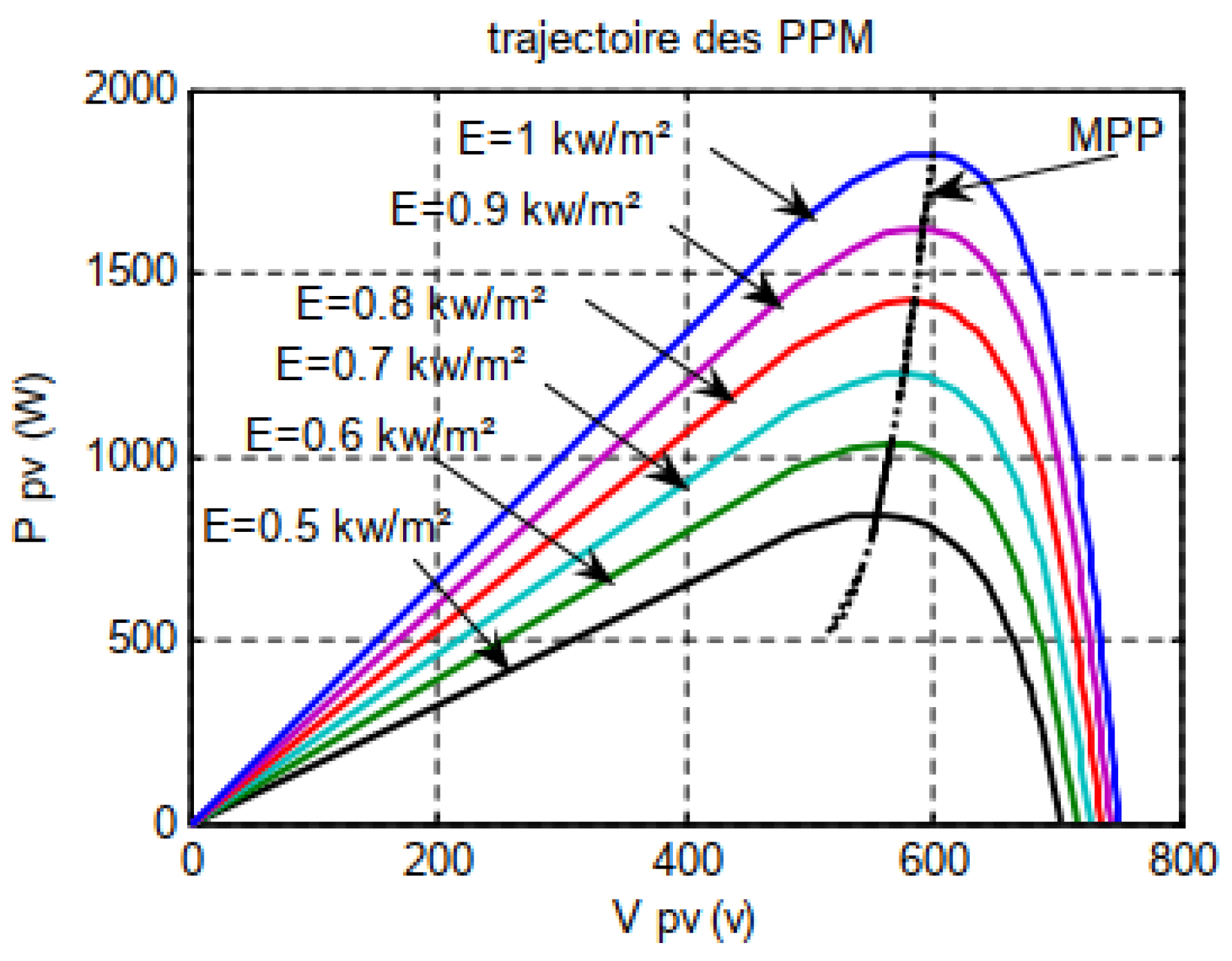
Simulation results with Simulink show the trajectory of MPP under different solar irradiation values as illustrated in Figure 10.
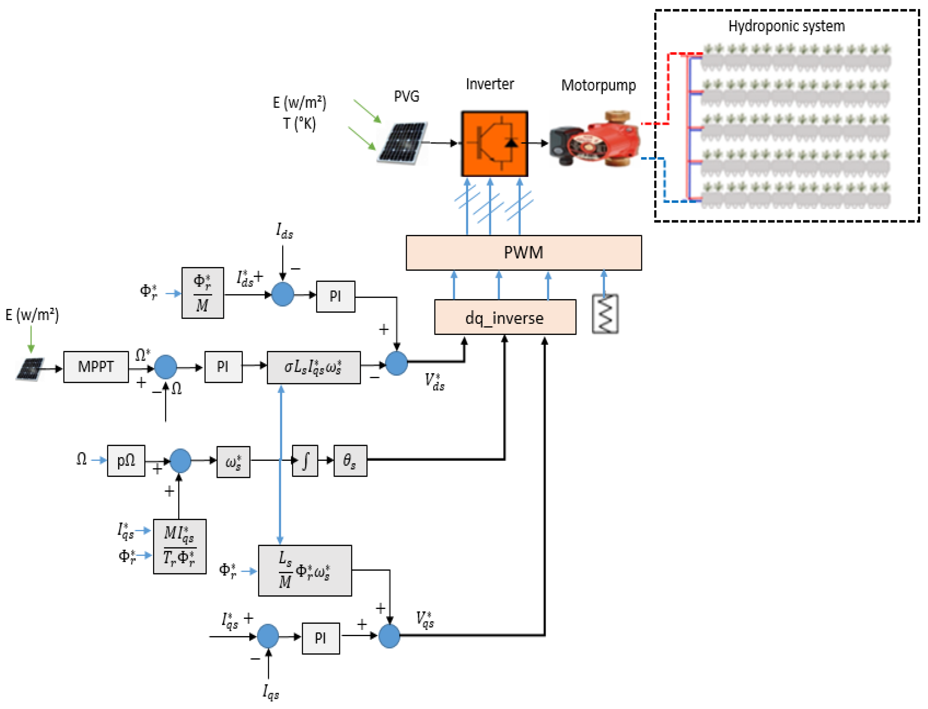
Finally, Figure 11 shows the synoptic diagram of the PV-HG system with the field-oriented control and the MPPT.

2.4. Simulation result of the PV-HG system with Matlab/Simulink

Using Matlab's Simulink tool, we simulate the developed model of the PV-HG controlled system under different values of solar irradiance and see its effects on the characteristic variables of the stand-alone PV-HG conditioning system.
Figure 12 (a) shows the variation of solar radiation at 800 W/m2, 500 W/m2 and 600 W/m2. Thanks to the MPPT algorithm developed by Marouani et al. [55] and implemented in this work, the PV current and the intermediate circuit voltage are optimally evaluated, which contributes to maximizing the power output of the PV generator, as shown in Figure 12 (b) and (c).
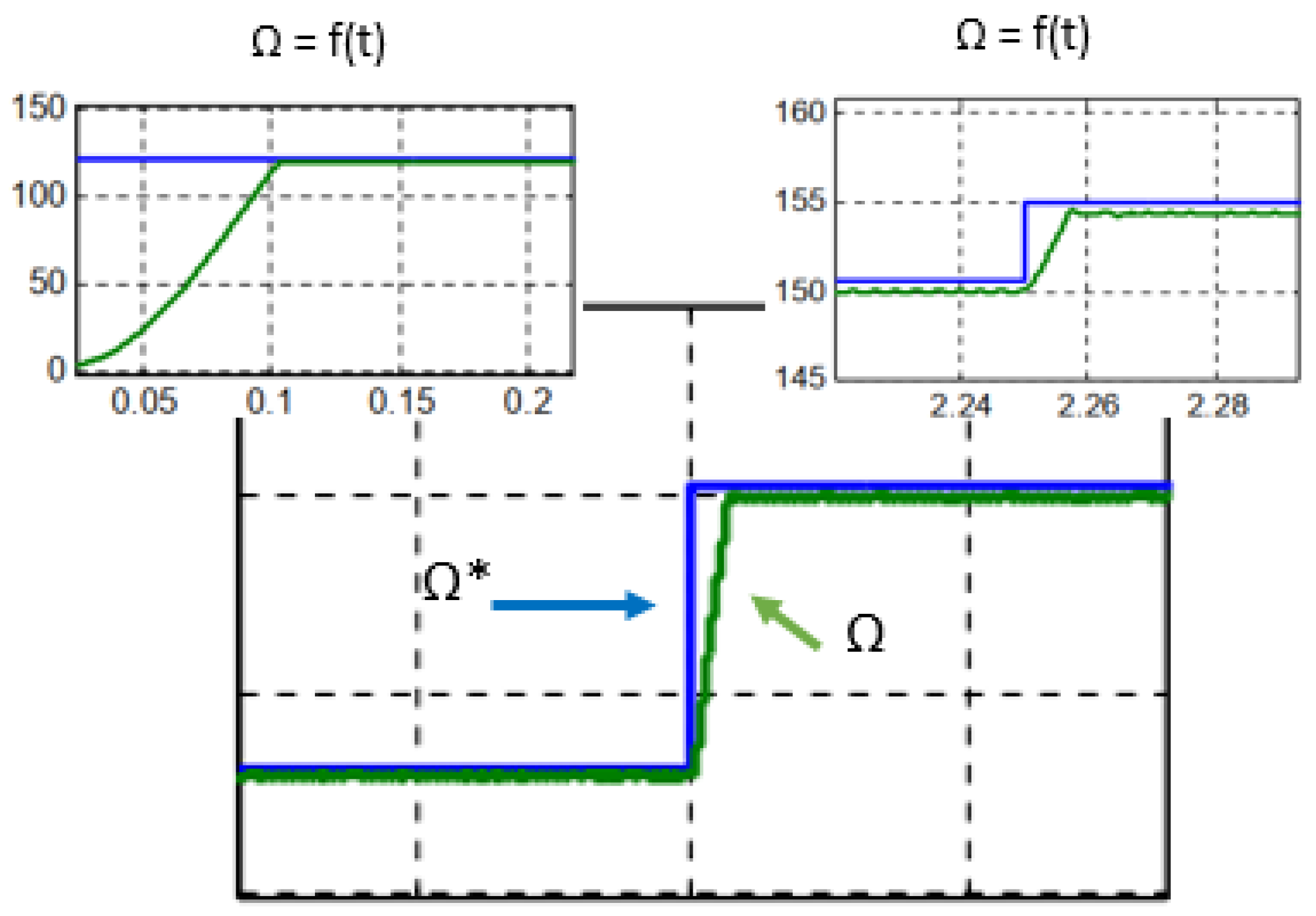
Figure 13 shows the reference and measured speed waveforms of the asynchronous motor under solar irradiation variation. We can see that the measured speed profile follows the reference one, proving the effectiveness of the MPPT and the FOC developed in this study.
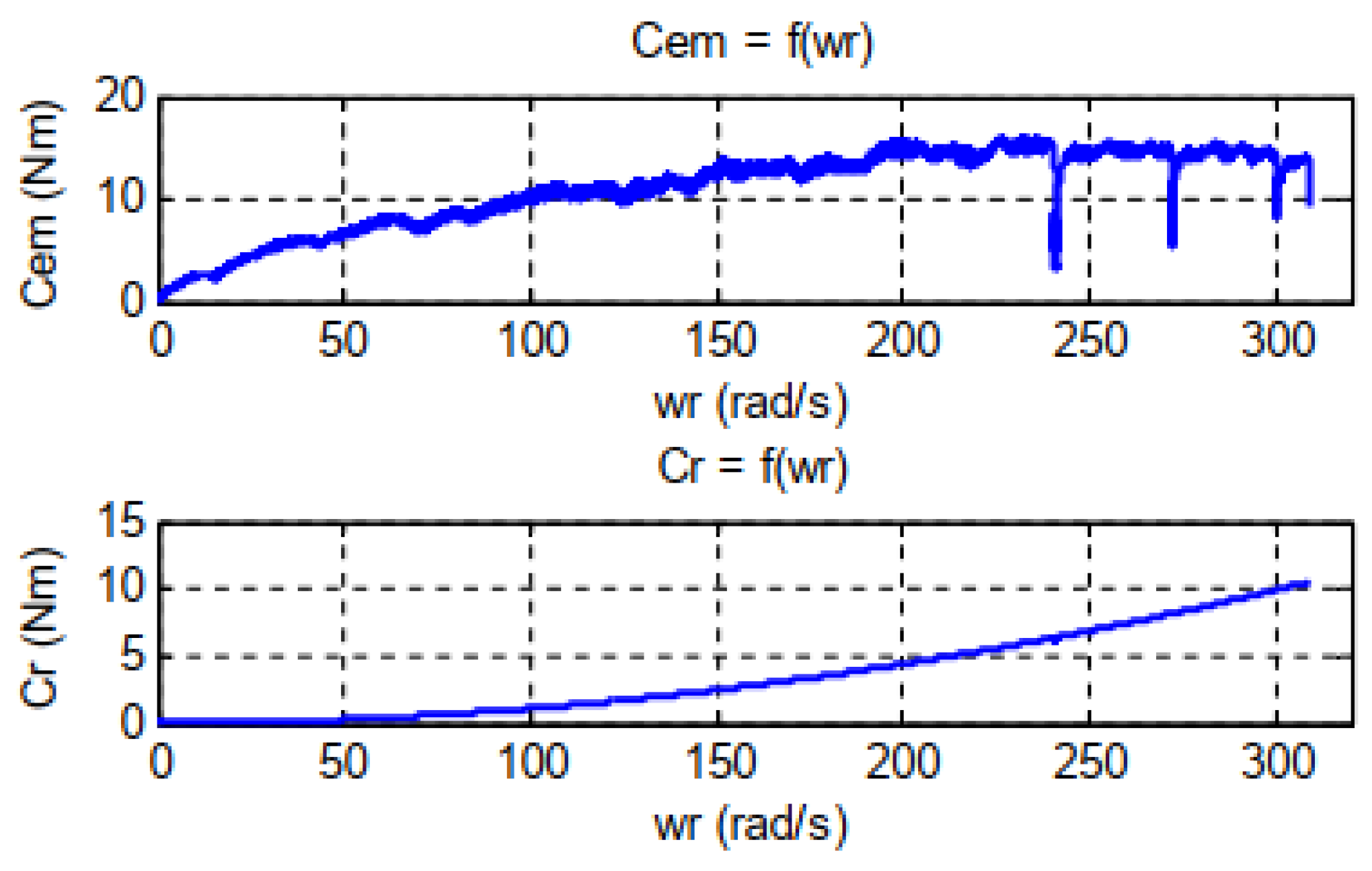
In Figure 14, we can also see the variation of the resistance and electromagnetic pairs versus the speed of the induction motor, which proves the effectiveness of the proposed simulation study.
It appears that the pump speed and water flow are affected by the changes in climatic parameters, proving that the system performances are optimized even under deteriorated climatic conditions. This is shown in Figure 15.
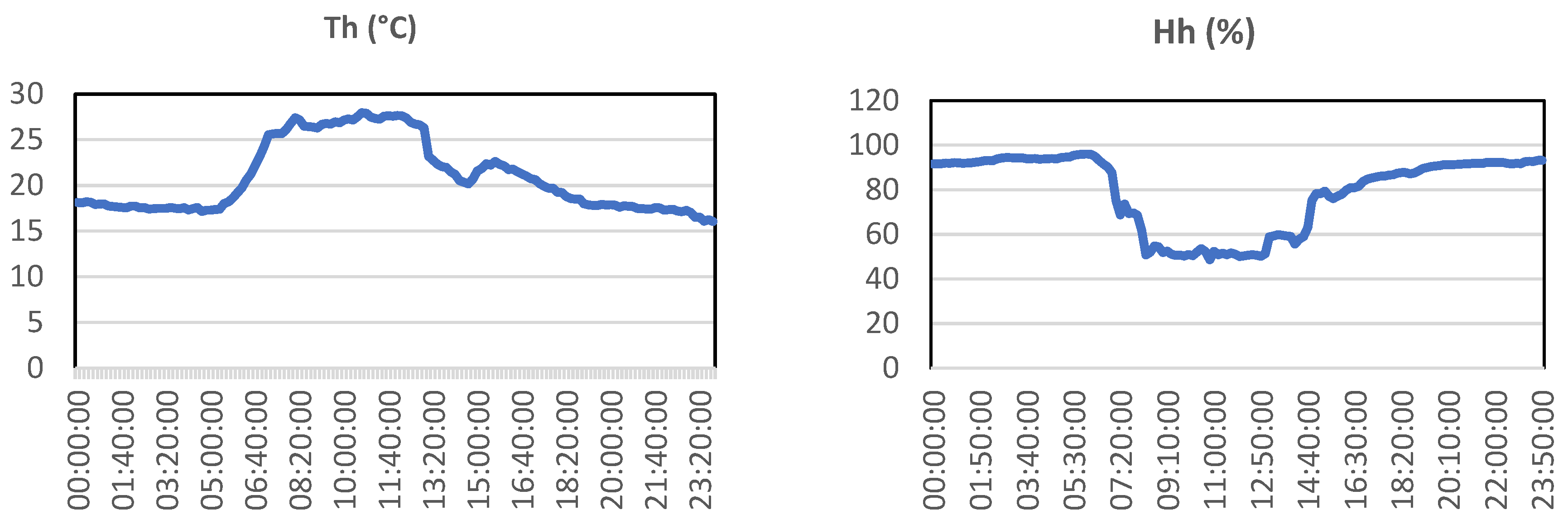
The temperature and humidity of the PV-HG in the heating system are shown in Figure 16.

3. Experimental set-up

3.1. Implementation of Smart PV_HG control parameters

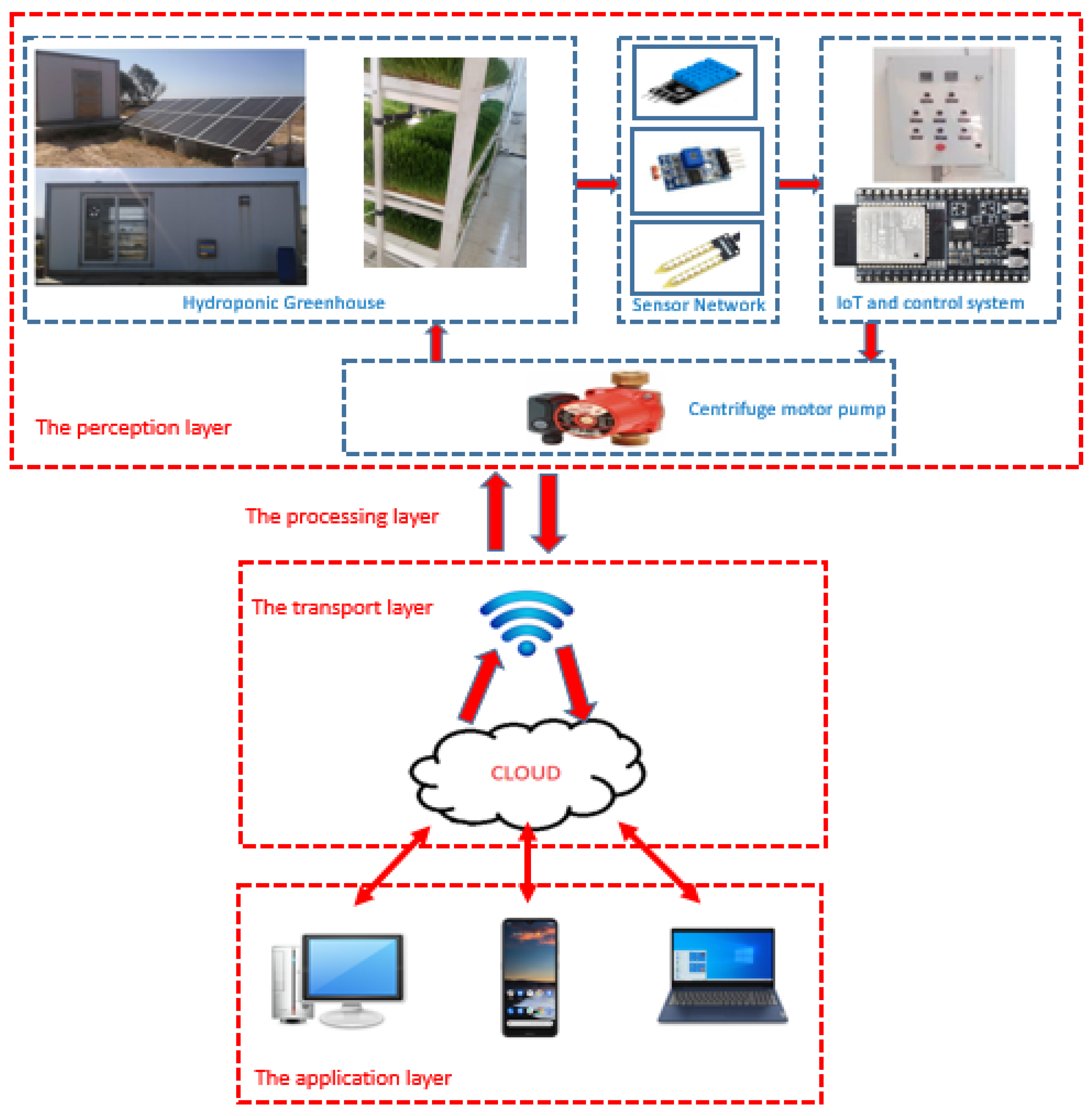
The goal of deploying IoT infrastructure for PV Hydroponic Greenhouse automation is to transform it into a connected system capable of achieving complete system perception, reliable data transmission and intelligent processing of its environmental parameters. The greenhouse environment is controlled by a set of sensors and actuators connected to a real-time measurement and alarm system. The information provided by the sensors is transferred to the microcontroller that will in turn integrate all the data into a single platform, analyze it and then make a decision by interacting remotely with the user via the internet: the Wi-Fi connection with the cloud allows recorded data to be transmitted and stored in databases. Subsequently, actuators such as the nutrient tank, water pumps and fans are used to execute the user command.
In this work, we have chosen to implement an IoT solution for remote control of internal and external parameters of the plant such as lighting, internal and external temperature, relative humidity, and soil moisture.

3.1.1. Temperature and humidity sensor

Temperature is one of the primary environmental factors that affect plant growth and development. The ideal temperature range for most plants is between 65-75 °F (18-24 °C) [45]. Temperatures outside of this range can cause stress to the plants and affect their growth rate and overall health. High temperatures can cause wilting and dehydration, while low temperatures can slow down growth and even cause damage to the plant's tissues. Therefore, maintaining the ideal temperature range is crucial for optimal plant growth and development. We use a DHT11 sensor to measure the ambient temperature inside and outside the greenhouse. This sensor is versatile and inexpensive, and it can monitor air temperature and humidity using an NTC negative temperature coefficient thermistor and a capacitive sensor module. It is impressive that the sensor generates a digital signal at its output pin with a reading accuracy of +- 5 °C and a sampling frequency of less than 0.5 Hz for temperatures between 40 and 150 °C.

3.1.2. Soil moisture sensor

To maintain optimal humidity levels inside the greenhouse and ensure that the plants receive the right amount of moisture, a soil humidity sensor was utilized for regular monitoring and control.

3.1.3. Light intensity sensor

Lighting is indeed a crucial factor in promoting rapid photosynthesis for plant growth. It's interesting to note that the control of light intensity inside a greenhouse can be provided by an LDR sensor. This sensor consists of a photoconductive cell that is covered with a moisture-resistant coating and housed in a plastic housing. The best part is that the lighting intensity is adjusted automatically when the plant needs no light at night, which is a great way to ensure that the plants get the right amount of light they need to grow.

3.1.4. ESP32 microcontroller

The microcontroller used in this work is ESP32 type because of its many advantages such as low-power programming, Wi-fi capabilities. Rich PIO interface and MicroPython compatibility. Figure 17 illustrates a complete description of the smart PV-HG system equipped with all the IoT sensors and the ESP32.
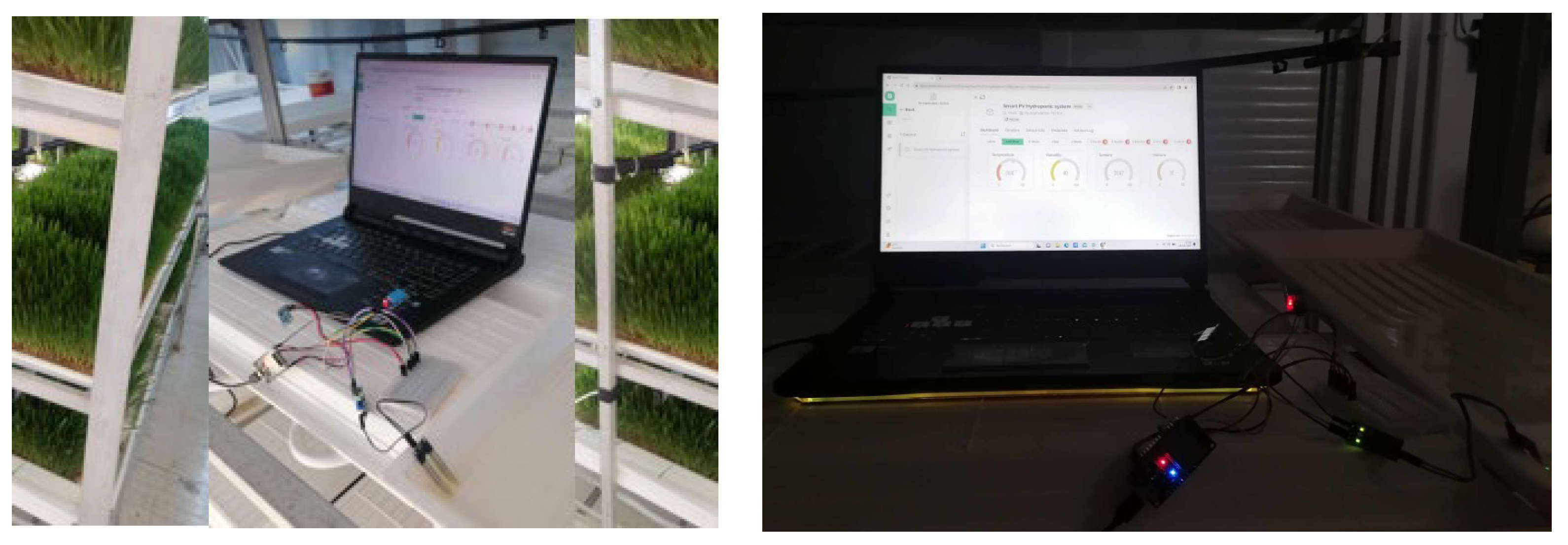
The smart IoT-based developed solution is implemented into the hydroponic greenhouse like in Figure 18.

3.1.5. Development of a web application for remote controlling of the smart PV-HG system

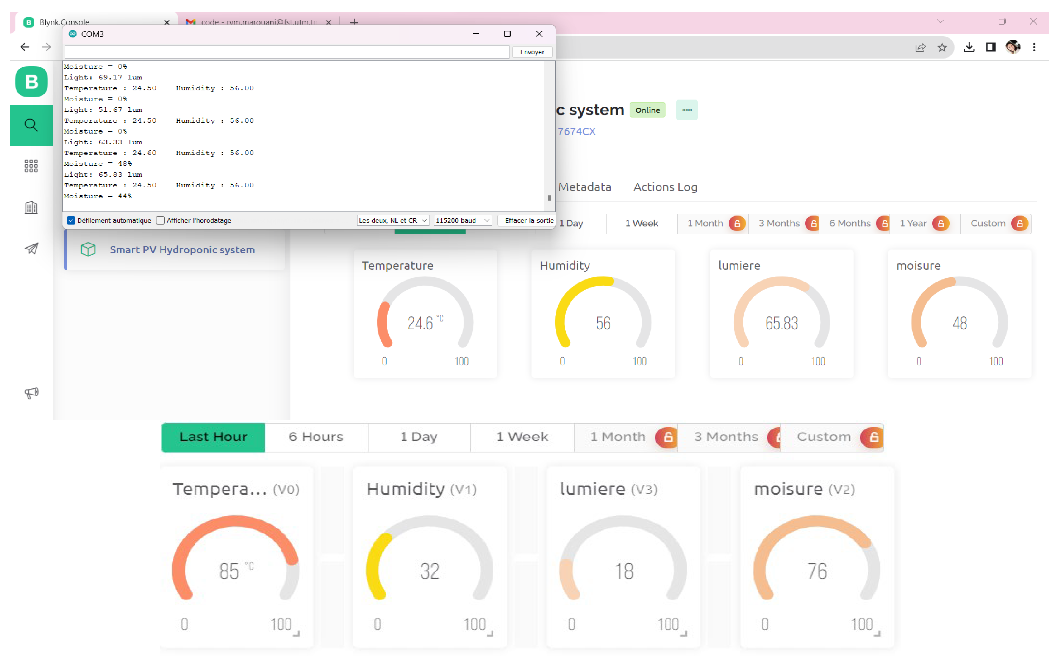
By using the blynk.console plateform, we have developed a web application for remote control of variables measured via the deployed intelligent sensors such as illustrated in Figure 19. This platform shows the variation of temperature, humidity, soil moisture and light intensity of the PV-HG.
By enabling remote control, farmers can easily adjust the system's parameters to ensure optimal growth and yield. This type of system can be an invaluable tool for maximizing yields and achieving optimal results, especially in areas where weather conditions can be unpredictable. With the right approach and attention to detail, we can create a sustainable and efficient growing environment that will help our plants flourish year-round.

3.2. Experimental and numerical results and discussion

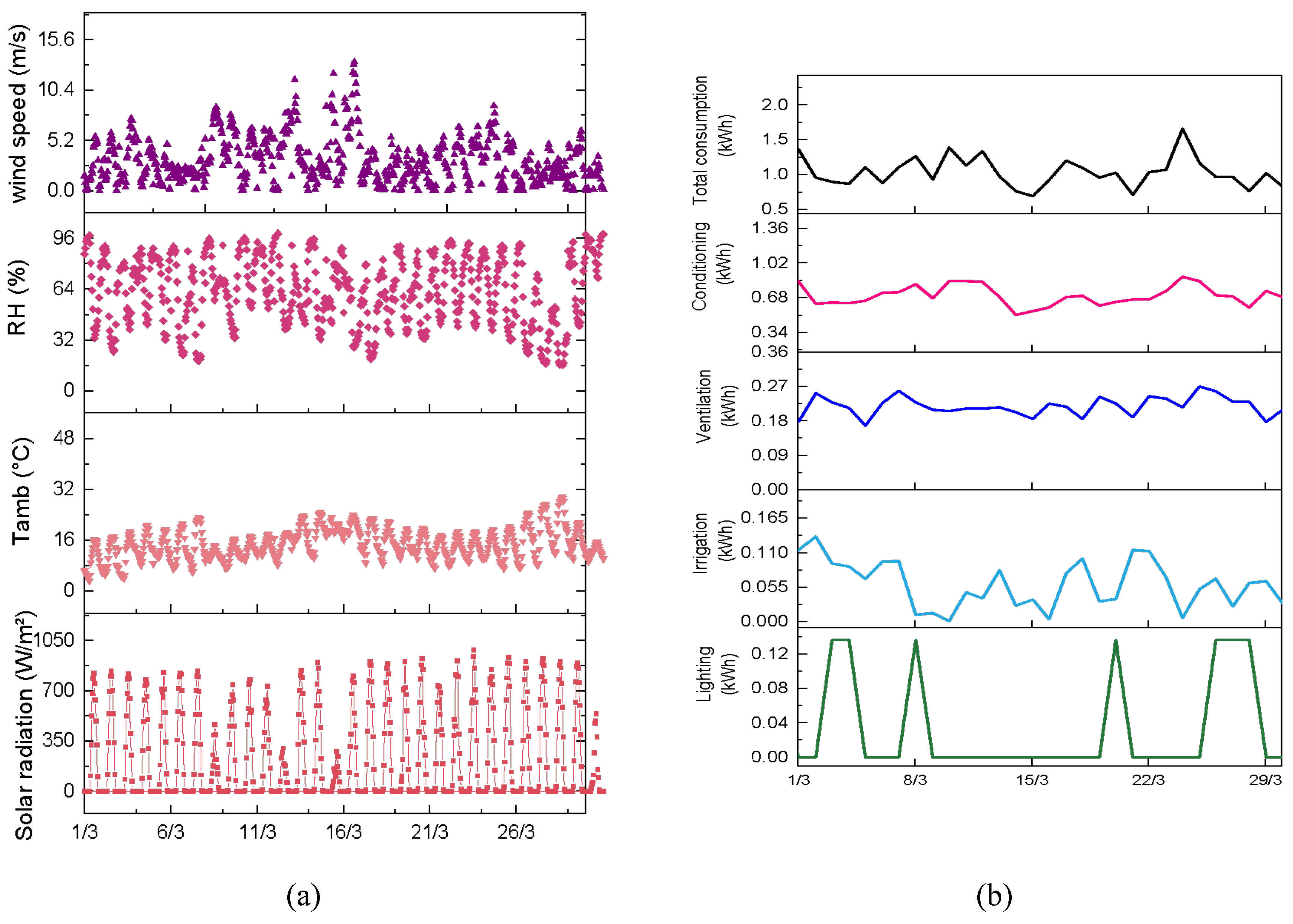
Figure 20 (a) details the climatic conditions recorded in March by an outdoor weather station on the hydroponic greenhouse platform. The data includes variations in global horizontal radiation, with ambient temperatures peaking at 28 °C and reaching a low of 6.26 °C. In addition, the relative humidity outdoors varies between 30% and 96% and averages 60%. The development of wind speed in April is shown with a maximum recorded speed between 5 and 11.23 m/s and a minimum speed of 0.64 m/s. Electricity consumption in the greenhouse is a dynamic aspect that fluctuates over time and is closely linked to the different growth phases of the plants grown, the operating states of various equipment and the specific needs of the vegetation. The nuanced interaction of these factors is clearly shown in Figure 20 (b), a visual representation of the evolving electricity consumption in March in the hydroponic greenhouse. The comprehensive breakdown of energy consumption shows that the total electrical energy consumption in the greenhouse varies between 0.7 and 1.7 kWh. It is noteworthy that the daily energy consumption of the thermal conditioning system reflects this fluctuation and constantly fluctuates between these two values throughout the month. This pattern reflects a higher demand for electrical energy during colder periods and indicates intensified operation of the system to maintain optimal temperature levels for the plants. In contrast, the ventilation system exhibits remarkable stability in power consumption, maintaining an almost constant value of about 0.25 kWh. This constant consumption plays a crucial role in homogenizing the indoor atmosphere of the greenhouse, ensuring a uniform and favorable environment for plant growth. In addition, the systems responsible for irrigation and lighting have interesting characteristics. Despite their important role in supporting plant life, their electricity consumption remains relatively low, ranging between 0.11 kWh and 0.12 kWh. This suggests that these systems operate efficiently and provide essential services to plants with minimal energy input. The main electricity consumers in the greenhouse are the thermal conditioning systems, which play a crucial role in maintaining an environment favorable for plant growth. What makes these systems special in this greenhouse is the use of a water reservoir that is designed to be a central element of the process. Essential for thermal control, this reservoir benefits from a sophisticated approach: it is heated by a solar water system in the winter months to maintain optimal conditions and cooled by a water-cooled heat pump in the summer. The mechanism works in tandem with a photovoltaic (PV) system that drives a centrifugal pump and is controlled by an environmental controller. This controller is equipped with intelligently defined parameters, including set temperatures that correspond to the optimum required in the greenhouse. This means that the system adapts dynamically to climate fluctuations and the specific needs of the plants. In the colder months the solar heating provides a sustainable energy supply, whilst in the warmer months the heat pump helps maintain cool conditions, all managed effectively by the environmental controls. This innovative approach not only optimizes energy efficiency through the use of renewable sources, but also demonstrates proactive and personalized management of the thermal environment in the greenhouse. By reducing reliance on traditional energy sources, this design demonstrates the intelligent integration of technologies to ensure optimal growing conditions while minimizing environmental impact.
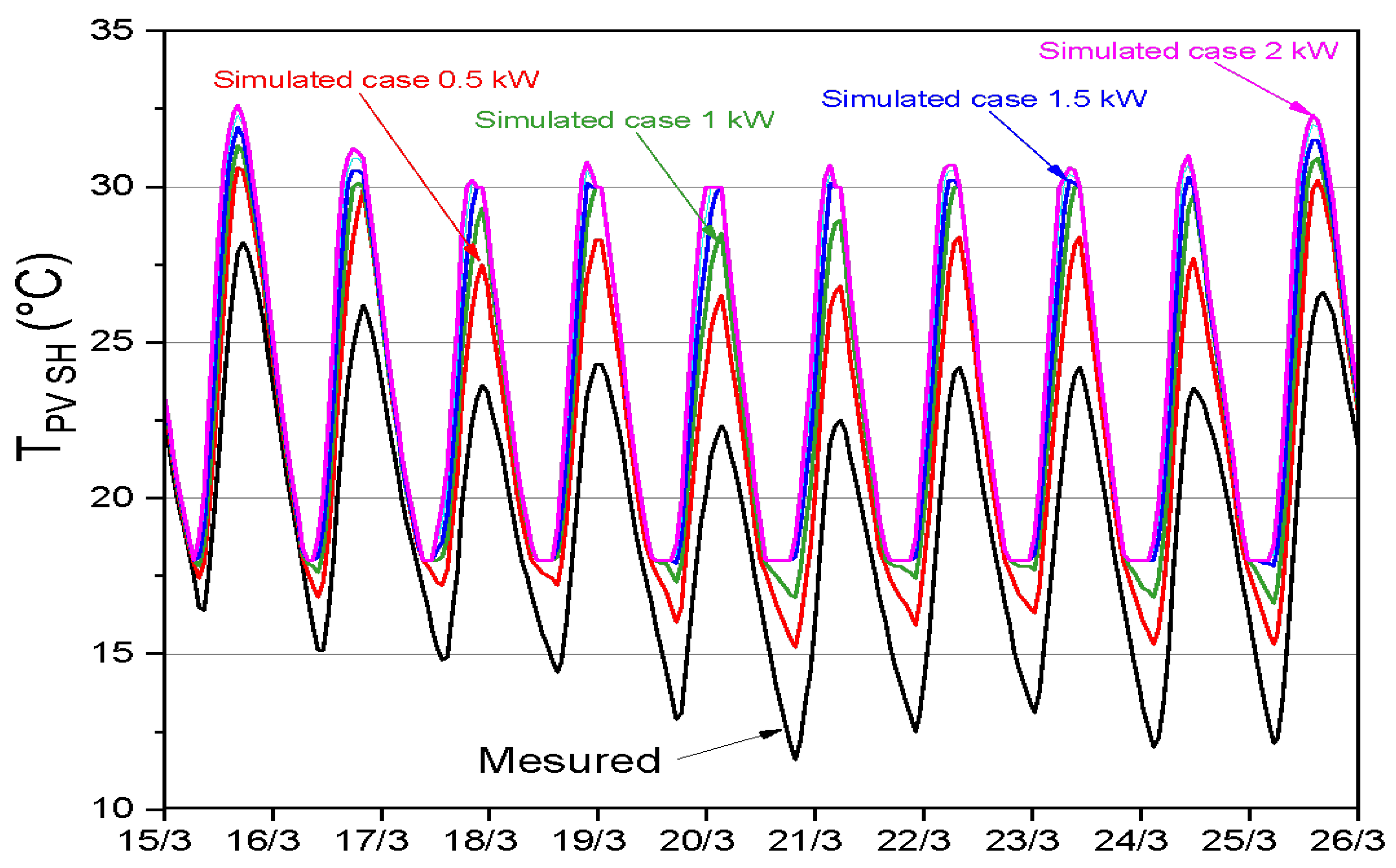
Figure 21 illustrates the effect of heating on the internal temperature of the hydroponic greenhouse with a centrifugal pump. In this section, an analysis of the effects of different heating powers on the indoor microclimate of the greenhouse is presented. The study includes two target temperatures: 18 °C at night and 30 °C during the day. Five cases are being investigated as in Table 2; The first case represents a greenhouse without a heating system (measured case), while the other four cases represent the heating powers of the centrifugal pump used for the hydroponic greenhouse: 0.5 kW, 1 kW, 1.5 kW and 2 kW, respectively. This figure shows the distribution of the indoor air temperature in a greenhouse with and without a heating system over a ten-day period for the months of March. It can be observed that the air temperature is below 18 °C, especially at night (case 0.5 kW). The heating of the hydroponic greenhouse was only activated when the temperature fell below 30 °C during the day and below 18 °C at night. After applying a power of 1 kW, the average temperature increased by 5 °C during the day and 6 °C at night compared to the initial greenhouse temperatures. With an output of 1.5 kW, the heating system covered the heat requirement for several nights, with the temperature increasing by an average of 8 °C during the day compared to the unheated greenhouse. However, in order to cover the daily heat requirements, the heating output had to be increased. On March 18, 20, and 20, the external thermal environment became colder, affecting the greenhouse microclimate and its heat requirements. By further increasing the power to 2 kW, the temperature fluctuations in the greenhouse became more stable around optimal day and night temperatures. What is striking is that an output of 1 kW was sufficient to cover the heat requirements of the hydroponic greenhouse at night.
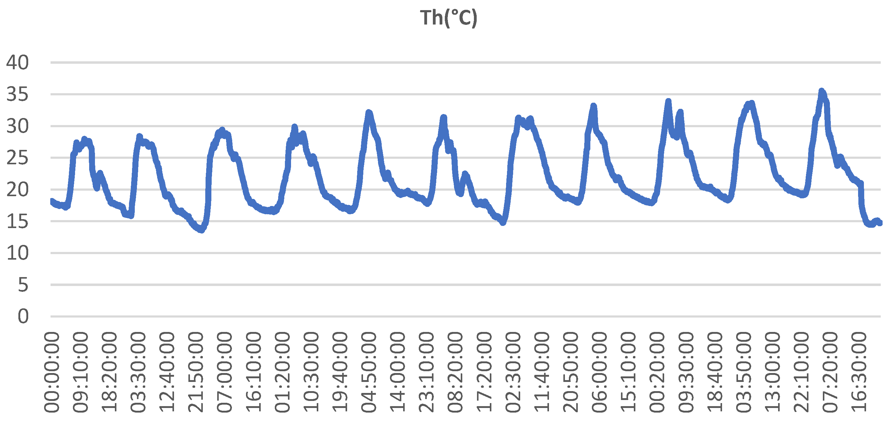
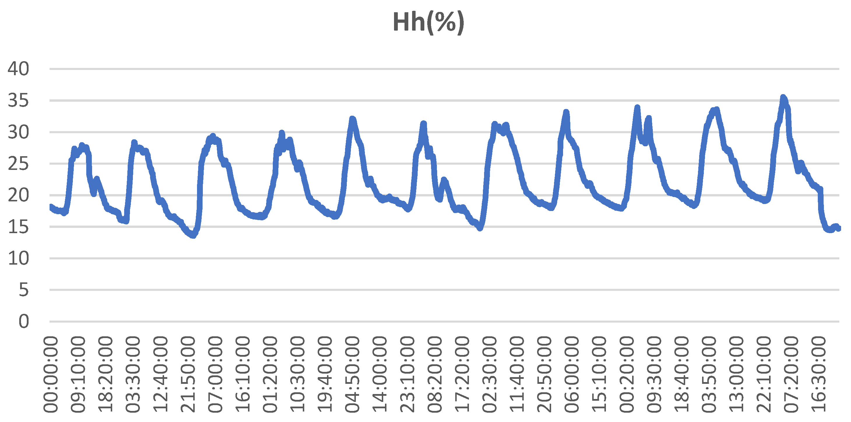
We can see also the monthly profile of the temperature and humidity of the PV-HG with the heating system respectively in Figure 22 and Figure 23.

6. Conclusions

The study aims to investigate and experiment with a smart stand-alone photovoltaic conditioning system of a hydroponic greenhouse. The main focus is on modeling and control to achieve optimal performance and efficiency. The study aims to gain valuable insights into the system's behavior and identify opportunities for enhancement through experimental research.
The first step involves mathematical modeling of the system's various components. Subsequently, control laws based on the Field Oriented PI Controller are developed to optimize system performance. A numerical simulation using Simulink is also presented to demonstrate the effectiveness of the proposed solution.
The study then moves on to implementing a smart IoT-based solution for remotely managing the hydroponic PV system's internal and external parameters. This solution uses DHT 11, LDR, and moisture sensors, along with the ESP32 microcontroller, to monitor and maintain the ideal growing conditions for the plants. A web application is designed to control the variation of temperature, humidity, soil moisture, and light intensity of the PV-HG.

Author Contributions

Conceptualization, R.M. and S.K.; methodology, R.M., S.K. and M.C.; software, R.M., S.K. and S.B.; validation, R.M., S.K. and S.B; formal analysis, M.C. and S.B.; investigation, M.C. and S.B.; resources, R.M., S.K. and A.C.; data curation, M.C. and A.C.; writing—original draft preparation, R.M..; writing—review and editing, R.M., M.C. and S.B.; visualization, S.B. and A.C.; supervision, A.C.; project administration, R.M. All authors have read and agreed to the published version of the manuscript.

Funding

The APC was funded by the research fund of University of Guyane, UMR Espace-Dev, Cayenne, French Guian.a

Data Availability Statement

Not applicable.

Acknowledgments

The authors especially thank the ATSSEE, the Physics Department of the Faculty of Science of Tunis, the Research and Technology Center of Energy of Bordj-Cedria, Tunisia, the Ministry of Higher Education and Scientific Research and University of Guyane, UMR Espace-Dev, Cayenne, French Guiana for creating favors in stakeholder communication, information collection, and funding provision during the implementation of the study.

Conflicts of Interest

The authors declare no conflict of interest.

References

  1. IRENA Renewable Energy in the Water, Energy and Food Nexus. International Renewable Energy Agency 2015, 1–125.
  2. Vadiee, A.; Martin, V. Energy Management Strategies for Commercial Greenhouses. Applied Energy 2014, 114, 880–888. [CrossRef]
  3. Qayyum, M.; Zhang, Y.; Wang, M.; Yu, Y.; Li, S.; Ahmad, W.; Maodaa, S.N.; Sayed, S.R.M.; Gan, J. Advancements in Technology and Innovation for Sustainable Agriculture: Understanding and Mitigating Greenhouse Gas Emissions from Agricultural Soils. Journal of Environmental Management 2023, 347, 119147. [CrossRef]
  4. Sarfraz, M.; Iqbal, K.; Wang, Y.; Bhutta, M.S.; Jaffri, Z. ul A. Role of Agricultural Resource Sector in Environmental Emissions and Its Explicit Relationship with Sustainable Development: Evidence from Agri-Food System in China. Resources Policy 2023, 80, 103191. [CrossRef]
  5. Shanmugavel, D.; Rusyn, I.; Solorza-Feria, O.; Kamaraj, S.K. Sustainable SMART Fertilizers in Agriculture Systems: A Review on Fundamentals to in-Field Applications. Science of The Total Environment 2023, 904, 166729. [CrossRef]
  6. Taoumi, H.; Lahrech, K. Economic, Environmental and Social Efficiency and Effectiveness Development in the Sustainable Crop Agricultural Sector: A Systematic in-Depth Analysis Review. Science of The Total Environment 2023, 901, 165761. [CrossRef]
  7. Bernzen, A.; Sohns, F.; Jia, Y.; Braun, B. Crop Diversification as a Household Livelihood Strategy under Environmental Stress. Factors Contributing to the Adoption of Crop Diversification in Shrimp Cultivation and Agricultural Crop Farming Zones of Coastal Bangladesh. Land Use Policy 2023, 132, 106796. [CrossRef]
  8. Wang, J.; Li, Z.; Zhu, Q.; Wang, C.; Tang, X. Review on Arsenic Environment Behaviors in Aqueous Solution and Soil. Chemosphere 2023, 333, 138869. [CrossRef]
  9. Rehman, H. ur; Hirvonen, J.; Sirén, K. Influence of Technical Failures on the Performance of an Optimized Community-Size Solar Heating System in Nordic Conditions. Journal of Cleaner Production 2018, 175, 624–640. [CrossRef]
  10. Dantas, J.L.D.; Theotokatos, G. A Framework for the Economic-Environmental Feasibility Assessment of Short-Sea Shipping Autonomous Vessels. Ocean Engineering 2023, 279, 114420. [CrossRef]
  11. Abdul-Wahab, S.A.; Charabi, Y.; Al-Mahruqi, A.M.; Osman, I. Design and Evaluation of a Hybrid Energy System for Masirah Island in Oman. International Journal of Sustainable Engineering 2020, 00, 288–297. [CrossRef]
  12. Salata, F.; Golasi, I.; Domestico, U.; Banditelli, M.; Lo Basso, G.; Nastasi, B.; de Lieto Vollaro, A. Heading towards the NZEB through CHP+HP Systems. A Comparison between Retrofit Solutions Able to Increase the Energy Performance for the Heating and Domestic Hot Water Production in Residential Buildings. Energy Conversion and Management 2017, 138, 61–76. [CrossRef]
  13. Omar, M.N.; Taha, A.T.; Samak, A.A.; Keshek, M.H.; Gomaa, E.M.; Elsisi, S.F. Simulation and Validation Model of Cooling Greenhouse by Solar Energy (P V) Integrated with Painting Its Cover and Its Effect on the Cucumber Production. Renewable Energy 2021, 172, 1154–1173. [CrossRef]
  14. Ghosal, M.K.; Tiwari, G.N. Mathematical Modeling for Greenhouse Heating by Using Thermal Curtain and Geothermal Energy. Solar Energy 2004, 76, 603–613. [CrossRef]
  15. Boughanmi, H.; Lazaar, M.; Bouadila, S.; Farhat, A. Thermal Performance of a Conic Basket Heat Exchanger Coupled to a Geothermal Heat Pump for Greenhouse Cooling under Tunisian Climate. Energy & Buildings 2015, 104, 87–96. [CrossRef]
  16. Boughanmi, H.; Lazaar, M.; Bouadila, S.; Farhat, A. Thermal Performance of a Conic Basket Heat Exchanger Coupled to a Geothermal Heat Pump for Greenhouse Cooling under Tunisian Climate. Energy and Buildings 2015, 104. [CrossRef]
  17. Chau, J.; Sowlati, T.; Sokhansanj, S.; Preto, F.; Melin, S.; Bi, X. Techno-Economic Analysis of Wood Biomass Boilers for the Greenhouse Industry. Applied Energy 2009, 86, 364–371. [CrossRef]
  18. Bibbiani, C.; Campiotti, C.A.; Schettini, E.; Vox, G. A Sustainable Energy for Greenhouses Heating in Italy: Wood Biomass. Acta Horticulturae 2017, 1170, 523–530. [CrossRef]
  19. Tractebel GUIDE DÉTAILLÉ “PROJETS D’ÉNERGIE RENOUVELABLE EN TUNISIE”; 2019;
  20. Msigwa, G.; Ighalo, J.O.; Yap, P.S. Considerations on Environmental, Economic, and Energy Impacts of Wind Energy Generation: Projections towards Sustainability Initiatives. Science of The Total Environment 2022, 849, 157755. [CrossRef]
  21. Uchman, W.; Kotowicz, J.; Sekret, R. Investigation on Green Hydrogen Generation Devices Dedicated for Integrated Renewable Energy Farm: Solar and Wind. Applied Energy 2022, 328, 120170. [CrossRef]
  22. Cossu, M.; Cossu, A.; Deligios, P.A.; Ledda, L.; Li, Z.; Fatnassi, H.; Poncet, C.; Yano, A. Assessment and Comparison of the Solar Radiation Distribution inside the Main Commercial Photovoltaic Greenhouse Types in Europe. Renewable and Sustainable Energy Reviews 2018, 94, 822–834. [CrossRef]
  23. Ezzaeri, K.; Fatnassi, H.; Bouharroud, R.; Gourdo, L.; Bazgaou, A.; Wifaya, A.; Demrati, H.; Bekkaoui, A.; Aharoune, A.; Poncet, C.; et al. The e Ff Ect of Photovoltaic Panels on the Microclimate and on the Tomato Production under Photovoltaic Canarian Greenhouses. Solar Energy 2018, 173, 1126–1134. [CrossRef]
  24. Alinejad, T.; Yaghoubi, M.; Vadiee, A. Thermo-Environomic Assessment of an Integrated Greenhouse with an Adjustable Solar Photovoltaic Blind System. Renewable Energy 2020, 156, 1–13. [CrossRef]
  25. Global Energy Review 2020. Global Energy Review 2019 2020. [CrossRef]
  26. Faraji, J.; Hashemi-Dezaki, H.; Ketabi, A. Multi-Year Load Growth-Based Optimal Planning of Grid-Connected Microgrid Considering Long-Term Load Demand Forecasting: A Case Study of Tehran, Iran. Sustainable Energy Technologies and Assessments 2020, 42, 1–51. [CrossRef]
  27. Duarte, R.; García-Riazuelo, Á.; Sáez, L.A.; Sarasa, C. Analysing Citizens’ Perceptions of Renewable Energies in Rural Areas: A Case Study on Wind Farms in Spain. Energy Reports 2022, 8, 12822–12831. [CrossRef]
  28. Minoofar, A.; Gholami, A.; Eslami, S.; Hajizadeh, A.; Gholami, A.; Zandi, M.; Ameri, M.; Kazem, H.A. Renewable Energy System Opportunities: A Sustainable Solution toward Cleaner Production and Reducing Carbon Footprint of Large-Scale Dairy Farms. Energy Conversion and Management 2023, 293, 117554. [CrossRef]
  29. Alturki, F.A.; Al-Shamma’a, A.A.; Farh, H.M.H.; AlSharabi, K. Optimal Sizing of Autonomous Hybrid Energy System Using Supply-Demand-Based Optimization Algorithm. International Journal of Energy Research 2021, 45, 605–625. [CrossRef]
  30. Cherif, D.; Bouadila, S. Enhancing Crop Yield in Hydroponic Greenhouses : Integrating Latent Heat Storage and Forced Ventilation Systems for Improved Thermal Stratification (Under Review). Thermal Science and Engineering Progress 2023, TSEP-D-23-, 102163. [CrossRef]
  31. Boccalatte, A.; Fossa, M.; Sacile, R. Modeling, Design and Construction of a Zero-Energy PV Greenhouse for Applications in Mediterranean Climates. Thermal Science and Engineering Progress 2021, 25, 101046.
  32. Aziz, A.S.; Tajuddin, M.F.N.; Zidane, T.E.K.; Su, C.L.; Alrubaie, A.J.K.; Alwazzan, M.J. Techno-Economic and Environmental Evaluation of PV/Diesel/Battery Hybrid Energy System Using Improved Dispatch Strategy. Energy Reports 2022, 8, 6794–6814. [CrossRef]
  33. Li, J.; Liu, X.; Han, X.; Wei, S.; Novakovic, V. Comparative Study on Shading Performance of MHP-PV/T inside and Outside Chinese Greenhouse in Winter. Solar energy 2022, 240, 269–279.
  34. Yildiz, A.; Ozgener, O.; Ozgener, L. Exergetic Performance Assessment of Solar Photovoltaic Cell (PV) Assisted Earth to Air Heat Exchanger (EAHE) System for Solar Greenhouse Cooling. Energy and Buildings 2011, 43, 3154–3160. [CrossRef]
  35. Baddadi, S.; Bouadila, S.; Ghorbel, W.; Guizani, A. Autonomous Greenhouse Microclimate through Hydroponic Design and Refurbished Thermal Energy by Phase Change Material . Journal of Cleaner Production 2018, 11, 192. [CrossRef]
  36. Barbosa, G.L.; Almeida Gadelha, F.D.; Kublik, N.; Proctor, A.; Reichelm, L.; Weissinger, E.; Wohlleb, G.M.; Halden, R.U. Comparison of Land, Water, and Energy Requirements of Lettuce Grown Using Hydroponic vs. Conventional Agricultural Methods. International Journal of Environmental Research and Public Health 2015, 12, 6879–6891. [CrossRef]
  37. Xu, Z.; Elomri, A.; Al-Ansari, T.; Kerbache, L.; El Mekkawy, T. Decisions on Design and Planning of Solar-Assisted Hydroponic Farms under Various Subsidy Schemes. Renewable and Sustainable Energy Reviews 2022, 156, 111958. [CrossRef]
  38. Farooq, M.S.; Javid, R.; Riaz, S.; Atal, Z. IoT Based Smart Greenhouse Framework and Control Strategies for Sustainable Agriculture. IEEE Access 2022, 10, 99394–99420. [CrossRef]
  39. Sadek, N.; kamal, N.; Shehata, D. Internet of Things Based Smart Automated Indoor Hydroponics and Aeroponics Greenhouse in Egypt. Ain Shams Engineering Journal 2023, 102341. [CrossRef]
  40. Sudana, D.; Eman, D.; Suyoto Iot Based: Hydroponic Using Drip Non-Circulation System for Paprika. Proceeding - 2019 International Conference of Artificial Intelligence and Information Technology, ICAIIT 2019 2019, 124–128. [CrossRef]
  41. Fernandes, M.B.; Costa, B.A.; Lemos, J.M. Hydroponic Greenhouse Crop Optimization. 13th APCA International Conference on Control and Soft Computing, CONTROLO 2018 - Proceedings 2018, 270–275. [CrossRef]
  42. Chaiwongsai, J. Automatic Control and Management System for Tropical Hydroponic Cultivation. Proceedings - IEEE International Symposium on Circuits and Systems 2019, 2019-May, 1–4. [CrossRef]
  43. Al-Naemi, S.; Al-Otoom, A. Smart Sustainable Greenhouses Utilizing Microcontroller and IOT in the GCC Countries; Energy Requirements & Economical Analyses Study for a Concept Model in the State of Qatar. Results in Engineering 2023, 17, 100889. [CrossRef]
  44. Andrianto, H.; Suhardi; Faizal, A. Development of Smart Greenhouse System for Hydroponic Agriculture. 2020 International Conference on Information Technology Systems and Innovation, ICITSI 2020 - Proceedings 2020, 335–340. [CrossRef]
  45. Bouadila, S.; Baddadi, S.; Skouri, S.; Ayed, R. Assessing Heating and Cooling Needs of Hydroponic Sheltered System in Mediterranean Climate: A Case Study Sustainable Fodder Production. Energy 2022, 261, 125274. [CrossRef]
  46. Bouadila, S.; Baddadi, S.; Ben Ali, R.; Ayed, R.; Skouri, S. Deploying Low-Carbon Energy Technologies in Soilless Vertical Agricultural Greenhouses in Tunisia. Thermal Science and Engineering Progress 2023, 42, 101896. [CrossRef]
  47. Mahjoub, S.; Chrifi-Alaoui, L.; Drid, S.; Derbel, N. Control and Implementation of an Energy Management Strategy for a PV–Wind–Battery Microgrid Based on an Intelligent Prediction Algorithm of Energy Production. Energies 2023, 16, 1883. [CrossRef]
  48. Zaouche, F.; Rekioua, D.; Gaubert, J.P.; Mokrani, Z. Supervision and Control Strategy for Photovoltaic Generators with Battery Storage. International Journal of Hydrogen Energy 2017, 42, 19536–19555. [CrossRef]
  49. Samrat, N.H.; Ahmad, N. Bin; Choudhury, I.A.; Taha, Z. Bin Modeling, Control, and Simulation of Battery Storage Photovoltaic-Wave Energy Hybrid Renewable Power Generation Systems for Island Electrification in Malaysia. Scientific World Journal 2014, 2014. [CrossRef]
  50. Muñoz-Aguilar, R.S.; Dòria-Cerezo, A.; Puleston, P.F. Direct Synchronous-Asynchronous Conversion System for Hybrid Electrical Vehicle Applications. An Energy-Based Modeling Approach. International Journal of Electrical Power and Energy Systems 2013, 47, 264–279. [CrossRef]
  51. Ben Ali, R.; Bouadila, S.; Mami, A. Development of a Fuzzy Logic Controller Applied to an Agricultural Greenhouse Experimentally Validated. Applied Thermal Engineering 2018, 141, 798–810. [CrossRef]
  52. Wang, F.; Zhang, Z.; Mei, X.; Rodríguez, J.; Kennel, R. Advanced Control Strategies of Induction Machine: Field Oriented Control, Direct Torque Control and Model Predictive Control. Energies 2018, 11. [CrossRef]
  53. Marouani, R.; Sellami, M.A.; Mami, A. Cascade sliding mode control applied to a photovoltaic water pumping system with maximum power point tracker. 2014 International Conference on Advanced Technologies for Signal and Image Processing (ATSIP) March 2014. [CrossRef]
  54. Marouani, R.; Bacha, F, Cascade sliding mode control applied to a photovoltaic water pumping system with maximum power point tracker. 8th International Symposium on Advanced Electromechanical Motion Systems & Electric Drives Joint Symposium, 2009. ELECTROMOTION 2009. [CrossRef]
  55. Marouani, R.; Sellami, M.A.; Mami, A. Photovoltaic Water Pumping System Controlled by Cascade Sliding Mode. Research Journal of Applied Sciences, Engineering and Technology,7(20):4364-4369. [CrossRef]
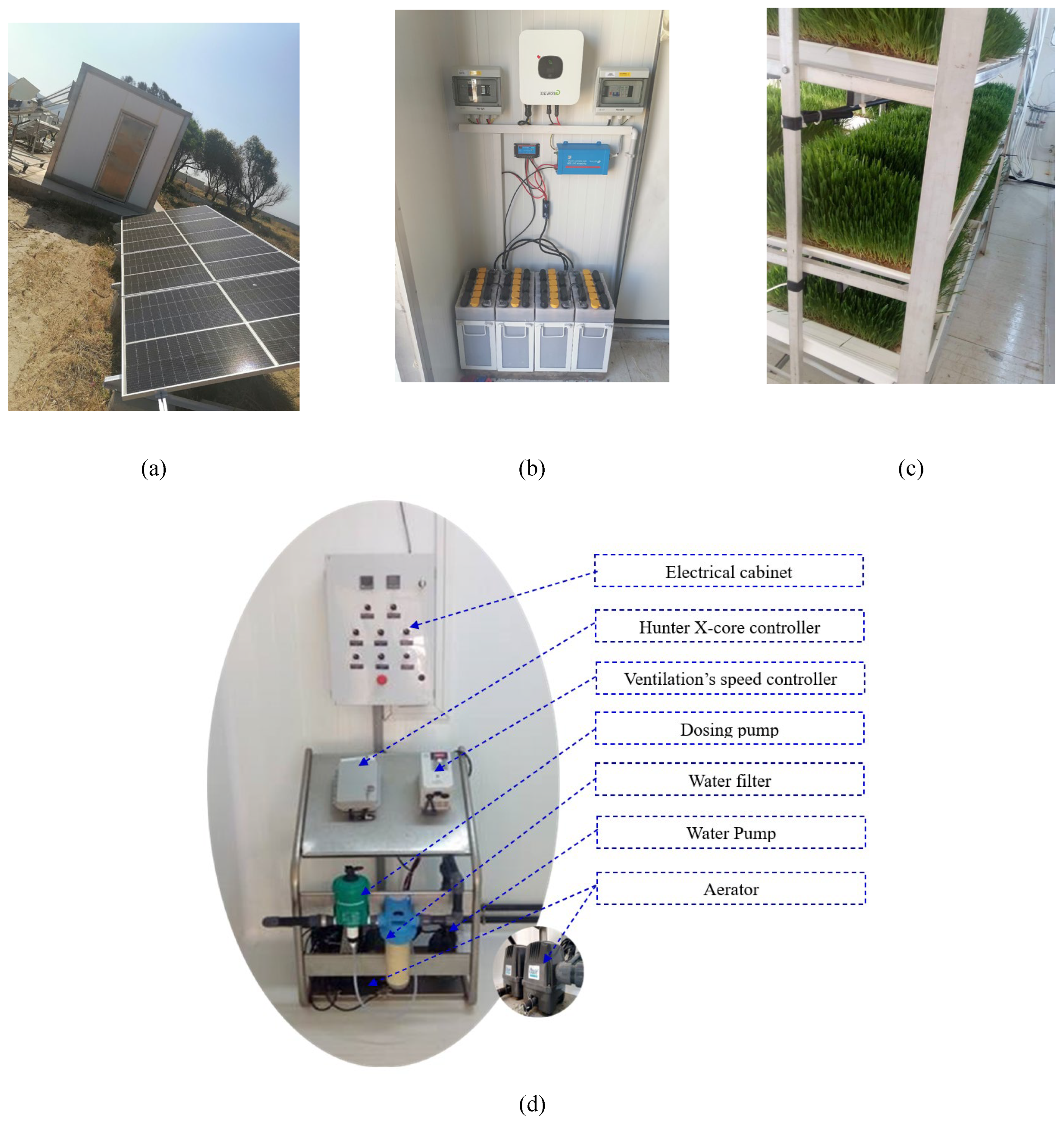
Figure 1. The PV alimentation source (a), the storage batteries system (b), the internal view of the PV-HG (c) and (d) Actuators.
Preprints 95768 g001
Figure 2. The synoptic scheme of the PV Hydroponic Greenhouse.
Preprints 95768 g002
Figure 3. The synoptic scheme of the stand-alone PV-HG conditioning system.
Preprints 95768 g003
Figure 4. Influence of variations in solar irradiation (a) and temperature (b) on characterized curves of PVG.
Preprints 95768 g004aPreprints 95768 g004b
Figure 5. The synoptic scheme of Hydroponic greenhouse.
Preprints 95768 g005
Figure 6. Schematic representation of the heat flux in hydroponic greenhouse.
Preprints 95768 g006
Figure 7. d and q axes decoupling in the motor pump model.
Preprints 95768 g007
Figure 8. Current regulation loop.
Preprints 95768 g008
Figure 9. Speed regulation loop.
Preprints 95768 g009
Figure 10. Trajectory of MPP under different solar irradiation values.
Preprints 95768 g010
Figure 11. The synoptic diagram of the PV-HG system with the field-oriented control and the MPPT.
Preprints 95768 g011
Figure 12. Solar irradiation profile (a), PV current (b), and DC-bus voltage (b) waveforms.
Preprints 95768 g012
Figure 13. Reference and measured motor speed waveforms.
Preprints 95768 g013
Figure 14. Resistive and electromagnetic versus speed.
Preprints 95768 g014
Figure 15. Pump speed and water flow waveforms.
Preprints 95768 g015
Figure 16. Temperature and humidity waveforms.
Preprints 95768 g016
Figure 17. The smart IoT-based PV-HG system.
Preprints 95768 g017
Figure 18. Implementation of the smart IoT-based PV-HG into the hydroponic greenhouse.
Preprints 95768 g018
Figure 19. Web application for the smart PV-HG parameters controlling.
Preprints 95768 g019
Figure 20. Climatic conditions (a) and Electrical energy consumption (b) of the PV-HG.
Preprints 95768 g020
Figure 21. Waveform of temperature inside the greenhouse with and without a heating system for ten days.
Preprints 95768 g021
Figure 22. Waveform of temperature inside the greenhouse with a heating system for 30 days.
Preprints 95768 g022
Figure 23. Waveform of humidity inside the greenhouse with a heating system for 30 days.
Preprints 95768 g023
Table 1. Actuators used in the hydroponic greenhouse.
Equipment (units) Technical specifications Power (kW)
Heat pump Absorption chiller (NH3/H2O), model GA Line ACF 60-00 of the ROBUR brands 17.72
Device for oxygenation (2) AquaOxy 4800 0.06
Variable speed control (1) CHINT NVF2-1.5/TS4 inverter 0.9
Fan type 1 and 2 (2/1) THERMIVENT extractors 0.250/0.05
Controller for irrigation (1) Hunter X-core controller 0.010
Centrifugal water pump (2) DAB, KPS 30/16 M 0.370
Dosing pump (1) Green Line Dosatron D25 0.01
Lighting fixture (8) Fluorescent lamp 0.016
Table 2. Daily power of the centrifugal pump.
Daily power of the centrifugal pump (kW) Studied cases
0 Measured case
0.5 Simulated case 0.5
1 Simulated case 1
1.5 Simulated case 1.5
2 Simulated case 2
Disclaimer/Publisher’s Note: The statements, opinions and data contained in all publications are solely those of the individual author(s) and contributor(s) and not of MDPI and/or the editor(s). MDPI and/or the editor(s) disclaim responsibility for any injury to people or property resulting from any ideas, methods, instructions or products referred to in the content.
Copyright: This open access article is published under a Creative Commons CC BY 4.0 license, which permit the free download, distribution, and reuse, provided that the author and preprint are cited in any reuse.
Prerpints.org logo

Preprints.org is a free preprint server supported by MDPI in Basel, Switzerland.

Subscribe

© 2024 MDPI (Basel, Switzerland) unless otherwise stated