1. Introduction
The Modular steel buildings (MSBs) are construction systems made of repeating pieces known as prefabricated prefinished modules. This system has quickly gained popularity in many countries as it offers several benefits, including fast-track construction, off-site construction, cost-effectiveness, less site waste, and lower environmental impact [
1,
2,
3]. Corner-supported modular building shown in
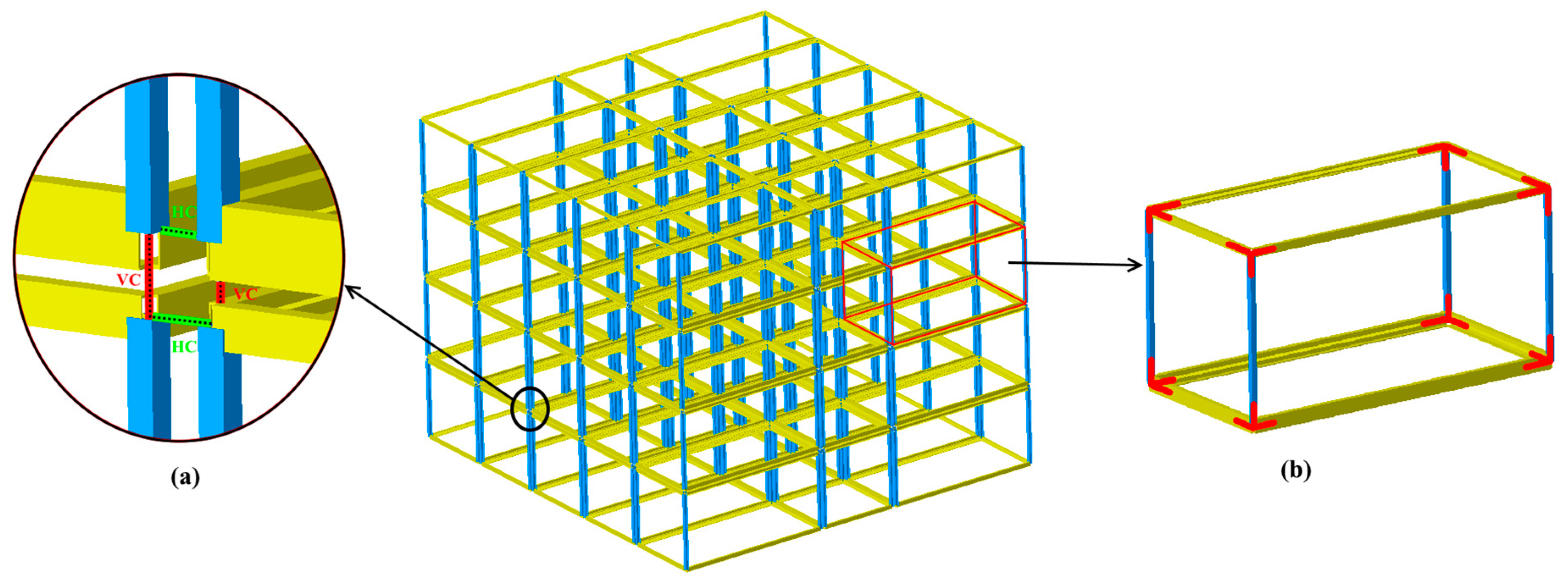
Figure 1 is one type of MSB in which each module is tied at its corners by horizontal connections (HC) as well as vertical connections (VC), which are called inter-module connections (see
Figure 1(a)) and having intra-module connections,
Figure 1(b). The interconnection with corner posts is the sole component responsible for transferring loads from one module to another.
A typical structural layout for modular structures is comprised of stacked modules to carry gravity loads and a core system to mainly resist lateral loads [
4]. This paper presents the impact of a core system on the collapse capacity of the MSB against corner module loss scenarios by adopting the results of 9 different cases.
The inter-module connections act as the linking elements between modules for load distribution and efficient load transfer to the foundation. Since these connections play a key role in the stability of the entire building [
5], most of the research studies from the literature have been focused on the structural performance or constructional challenges [
6,
7,
8]. Lacy et al. [
6,
9] studied the stiffness of bolted connections and showed that rotational stiffness has a modest impact on global structural responses. It was concluded that simplified modelling of inter-module connections could accurately predict overall building response under gravity and lateral demands [
10]. Peng et al. [
11] developed a tenon inter-module connection using spring elements in Abaqus, which significantly lowered the computational expenses. Feng et al. [
12] studied the seismic performance of four types of inter-module connection for modular box buildings, and the results showed that none satisfied Chinese code limitations such as inter-story drifts. Similarly, Peng et al. [
13] showed that a 12-story MSBs cannot meet the drift requirements against service wind loads.
Some notions have been put forward in recent research to overcome the former shortcomings, ranging from developing innovative inter-modular connections [
14,
15,
16] as well as precast concrete core wall systems [
17,
18,
19] to various module layouts [
20,
21].Therefore, a secondary system such as a core wall system is essential in mid- to high-rise MSB [
22]. Chua et al. [
18] and Yee [
23] investigated the lateral performance of a high-rise MSB with a central concrete core. Bi et al. [
19] also, studied the lateral performance of a multi-story MSB with two concrete cores under wind loads, as a case study located in China.
From the MSBs collapse perspective, several research has been undertaken. Luo et al. (2019) studied the steel-frame progressive collapse by assuming that all connections are rigid [
24]. However, actual connection behaviours would also be necessary to understand the extent of damage in the aftermath of a blast or fire events. Alembagheri et al. [
25,
26] and Sharafi et al. [
27] investigated the collapse capacity of rigid modular buildings in the macro model context in which the connections were modelled by translational axial and shear nonlinear springs. Also, their early work on the progressive collapse of a flexible six-story modular steel frame revealed that the global column buckling dominates the progressive collapse response of the building [
28]. The behaviour of semi-rigid joints is one of the issues that should be addressed in simplified numerical methods [
29,
30]. Thai et al. [
31] performed a parametric study on the progressive collapse of 12-story braced MSB. The results showed that the robustness of modular buildings is significantly increased by bracing system, as it decreases effective length of columns. Likewise, it was indicated that the MSB‘s ability to withstand collapse can be improved by up to 50% when wall panels are tied in each module [
32].
As using alternative lateral force resisting systems in mid- to high-rise MSBs to meet drift requirements is unavoidable, a comprehensive study on their role in collapse scenarios is essential. In the current literature, it is mostly done based on the progressive collapse of modular steel buildings without considering the contribution of the secondary systems such as shear wall (core) or bracing systems. This paper studies the dynamic response of corner-supported modular steel buildings incorporating a core wall system when subjected to progressive collapse scenarios, with a focus on recognizing the role of secondary systems. The primary aim of the current study is to provide insight into the impact of these systems on load redistribution and the structural robustness of the building during the loss of a corner module. For this purpose, 9 modular building cases are considered with four, eight and twelve-story and three different locations on the plan, for a core wall system. The inter-module connections are modelled using the macro-model-based finite element method. The guideline based on the alternative path method is used to study the collapse response of modular buildings, and the corner modules are considered a missing vertical load-bearing component. Then a parametric analysis is conducted to examine the effect of inter-module connection stiffness, intra-module joint rigidity, and plastic hinges on the MSBs robustness.
3. Simulated modular building
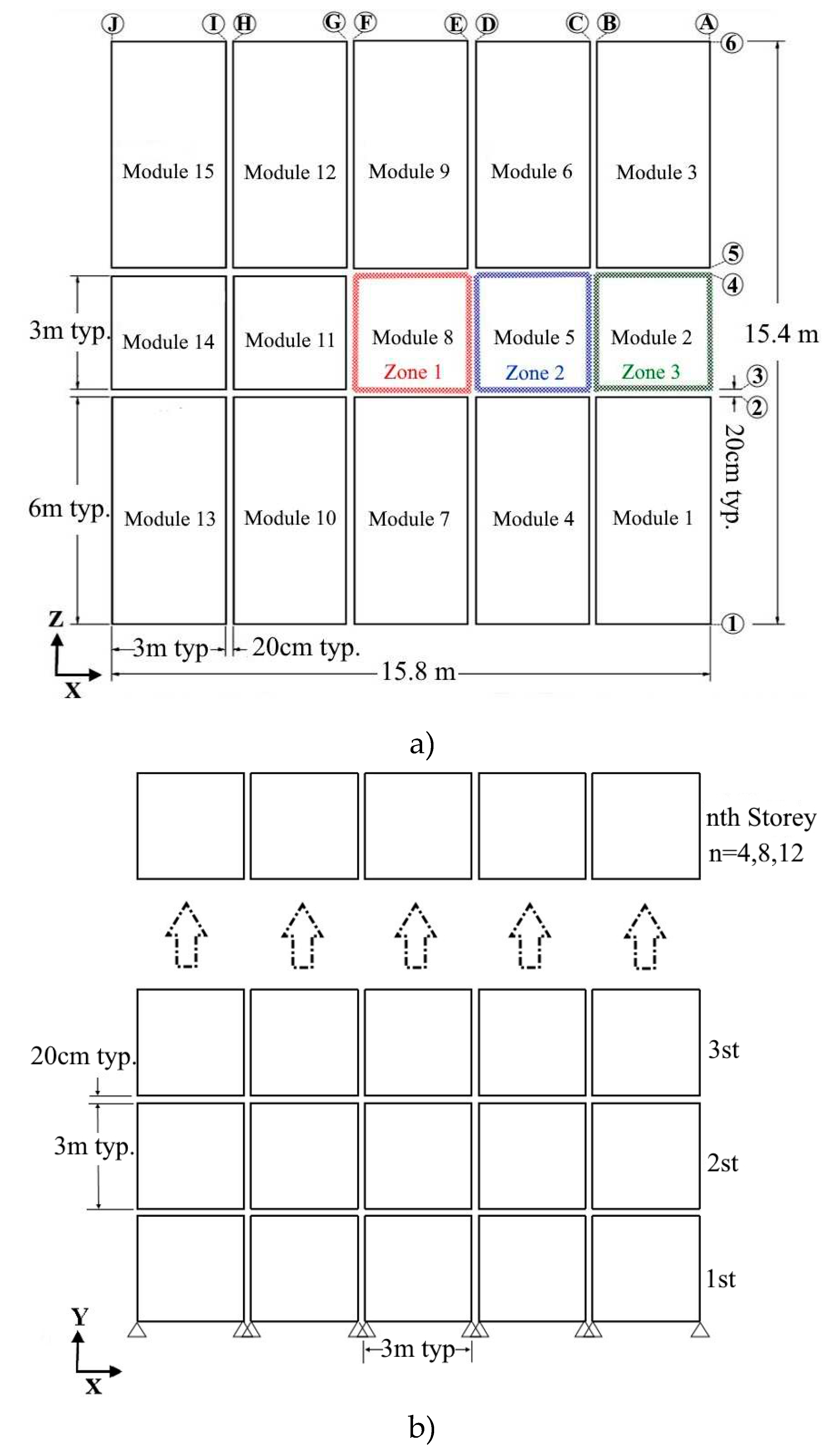
A typical plan shown in
Figure 3(a) is chosen to study the robustness of modular buildings with core. There are 15 modules in three rows, with the middle module considered a corridor. In this study, shear walls are in three zones: zone (1), zone (2), and zone (3). There are two types of modules; the first has a 6m length, 3m width, 3m height, and a total mass of 20 tones. The other has a 3m length, 3m width, 3m height, and a total mass of 10 tones. It should be noted that the mass of each module is calculated by adopting dead loads plus 25% of live loads specified by GSA guidelines [37]. The horizontal and vertical clearances between neighbouring modules are 0.2m, as depicted in
Figure 3(b). Three building heights are considered in this study.
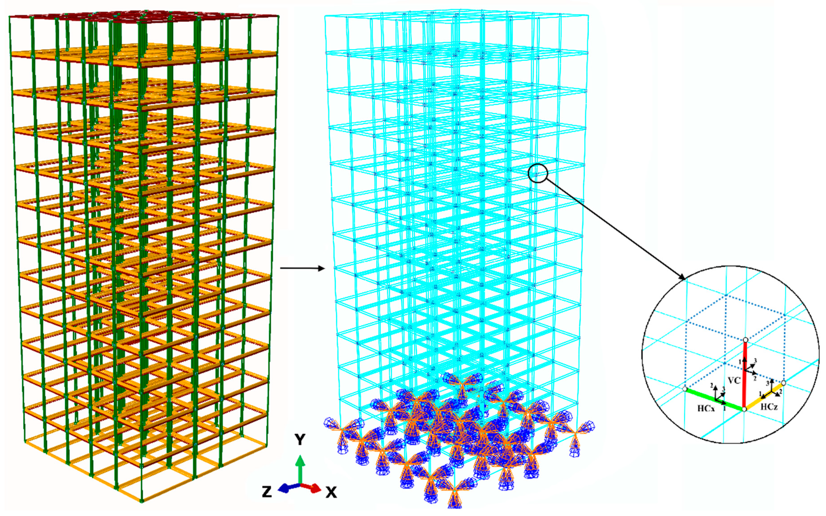
All buildings were designed in accordance with the requirements of AS1170 and AS4100 [40]. The design resulted in SHS 100×100×9 for columns, 180UB for floor beams, and 150UB for ceiling beams. The steel material for columns was assumed as a tri-linear elastoplastic [41] model with an initial yielding stress of 350 MPa, an ultimate strength of 490 MPa at a plastic strain of 0.02. For beams, however, steel is treated as an elastic material because plastic hinges are regarded at their ends. Further, a density of 7800 kg/m3, Young’s modulus of 200 GPa, and Poisson’s ratio of 0.25 were considered for steel material. A thickness of 250 mm was adopted for the concrete core wall with elastic material behaviour and the concrete density, Young’s modulus, and Poisson’s ratio were, respectively, assumed to be 2400 kg/m3, 30 GPa, and 0.3. The finite element (FE) mesh discretization developed in the Abaqus program is shown in
Figure 4. All beams and columns were modelled using 2-node linear beam in space (B31) elements and the core wall was simulated using 4-node doubly curved thin shell elements with reduced integration, hourglass control, and finite membrane strain (S4R). A tie constraint was adopted to link shell nodes to the adjacent beam nodes. A clamped restraint was adopted to fix column nodes to the ground.
This study had two types of connections: inter-module and intra-module connections. Adjacent Modules were connected to each other via inter-module connections including 6M24 class 10.9 bolts, simplified with two horizontal connectors (HCx, HCz) and one vertical connector (VC), depicted in
Figure 4.
A Cartesian connector element, available as a built-in connection in Abaqus, was defined with force-displacement relations proposed in [
6], as shown in
Figure 5. The Cartesian connection type connects two nodes where the response in three local connection directions is defined. It was assumed that vertical and horizontal connections were eliminated from the model after reaching their failure points as listed in
Table 1. Note that the rotational stiffness of inter-module connections was neglected based on previous research [
25] because the load-bearing mechanism in MSBs is primarily governed by shear transfer.
Intra-module connections, referred as beam-column connections within a module, were assumed to be rigid. However, concentrated plastic hinges were assigned to both ends of the beam element to consider the effects of local buckling. The hinges were modelled as rotational springs with a symmetric quadrilinear moment rotation relationship for positive and negative rotations. The capacity of these hinges was based on the theoretical moment-curvature (M-ɵ) relationships of the cross-sections using the ASCE41-17 provision [42].
The nonlinear dynamic analysis was performed using the implicit dynamic solver in Abaqus [43]. At first, an Eigenvalue buckling analysis was performed and buckling mode shapes were determined and imposed as an initial state to the model. This analyses that predict the collapse mechanism was performed using the subspace iteration method to extract the buckling modes. This analysis provides buckling eigenvalues and buckling modes which are used in the post-buckling analysis by determining the initial geometric imperfection. Next, the gravity loads including modules’ dead and live loads, were applied gradually through the quasi-static step. The corner module was eventually removed from the model within 0.0001 seconds, and the dynamic response of the remaining model was monitored until it reached the equilibrium state.
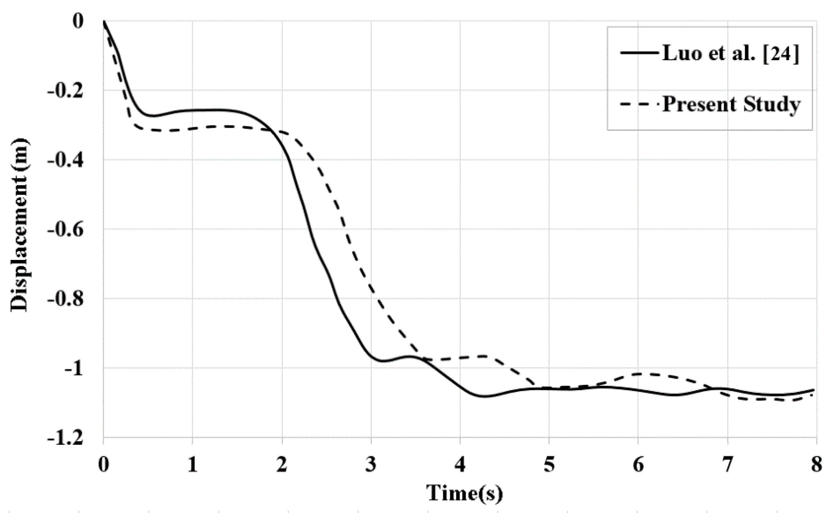
Due to the limited availability of experimental tests specifically addressing the dynamic collapse of modular buildings, the validation of the numerical modelling procedure presented in this study relies on the utilization of previously published numerical models. To achieve this, we developed a steel modular building, which had been previously examined by Luo et al. [50], employing the methodology described in this paper. As shown in
Figure 6, there is an acceptable agreement between The developed model that had been verified in our previous research [25] with the original model of Luo et al [
24].
4. Response under module loss scenario
The dynamic responses of different cases, reported in
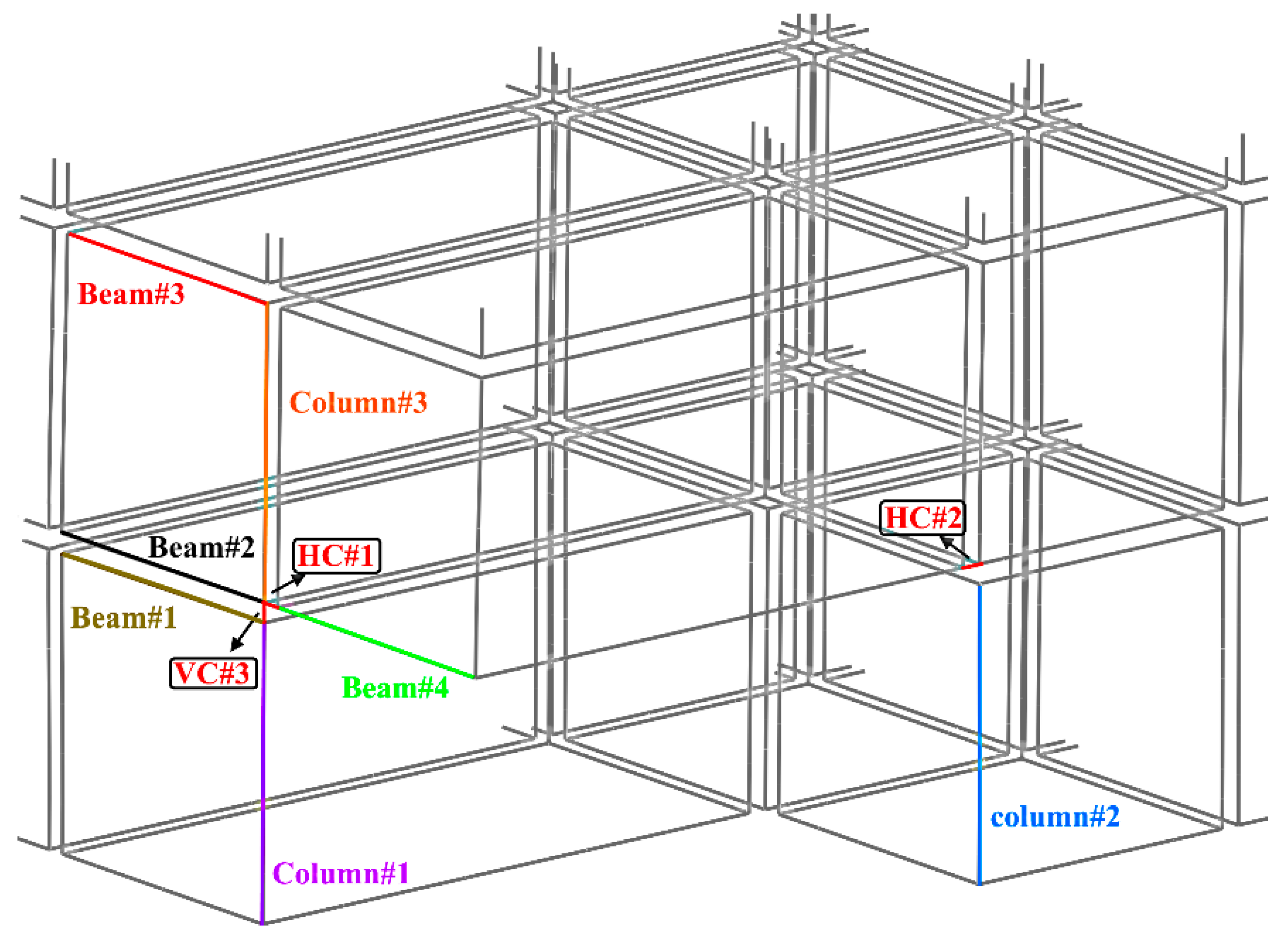
Table 2, are presented and compared in this section, to evaluate the core wall role in the building's robustness. To that end, the response history of corner roof displacements, the maximum stress of the shear wall, plastic hinges distribution, and internal forces in critical members in
Figure 7 are reported. Also, maximum dynamic to static response ratio: DSR = r
max,dyn/r
static; the dynamic increase factor: DIF = r
max,dyn/r
final; demand-capacity ratio: DCR and some design implications are addressed in this section. r
static is considered as a force at the end of Quasi-static gravity step and r
max,dyn is the maximum element force after corner modules removal.
4.1. 4-storey
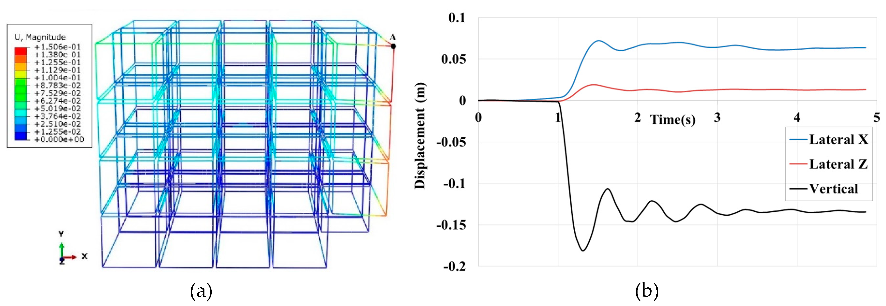
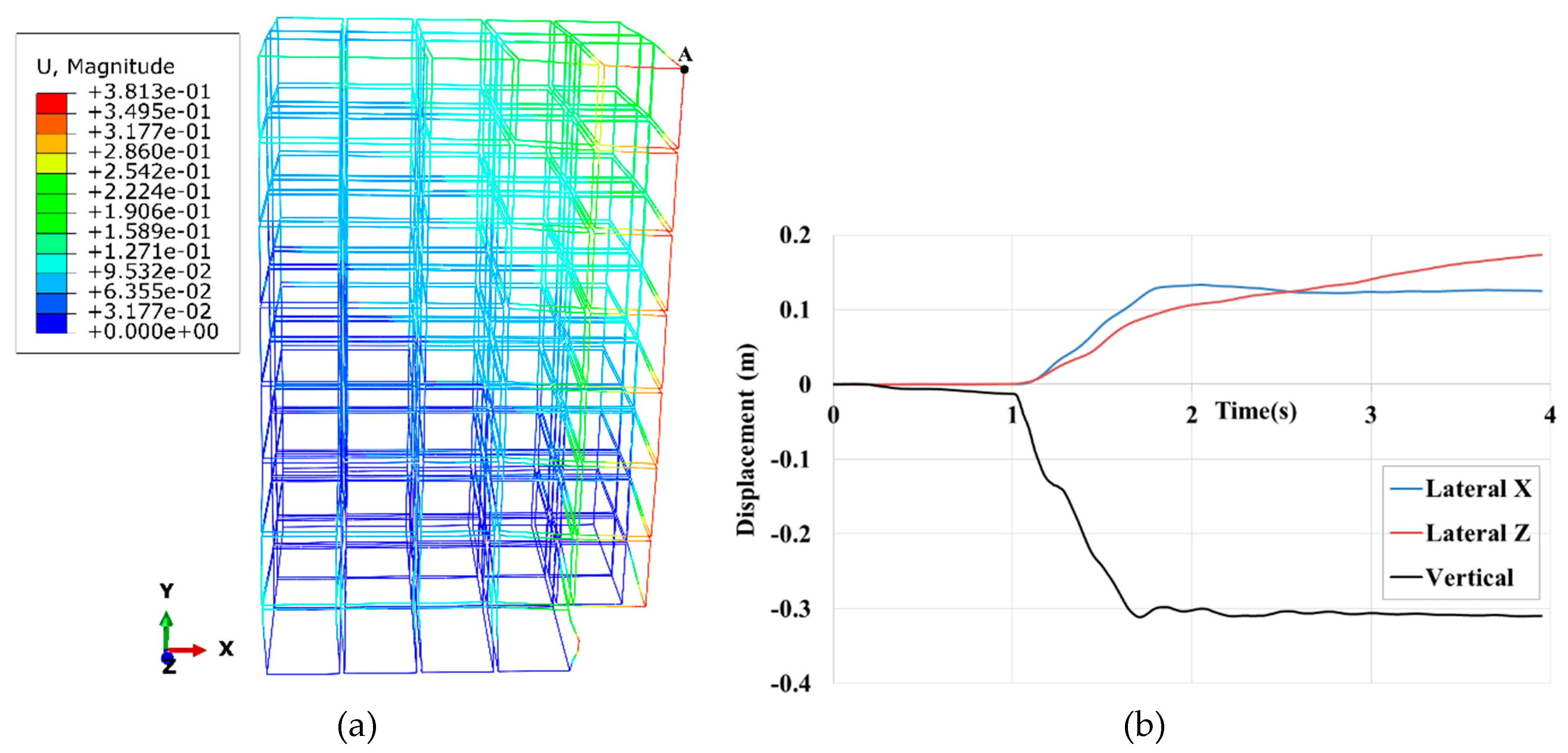
In the first case, the structure was robust after the corner module sudden removal because no column buckling occurred. The time history of lateral and vertical displacements of the roof corner, labelled A is shown in
Figure 8(a). The maximum vertical and lateral displacements are about 18cm and 7cm, respectively.
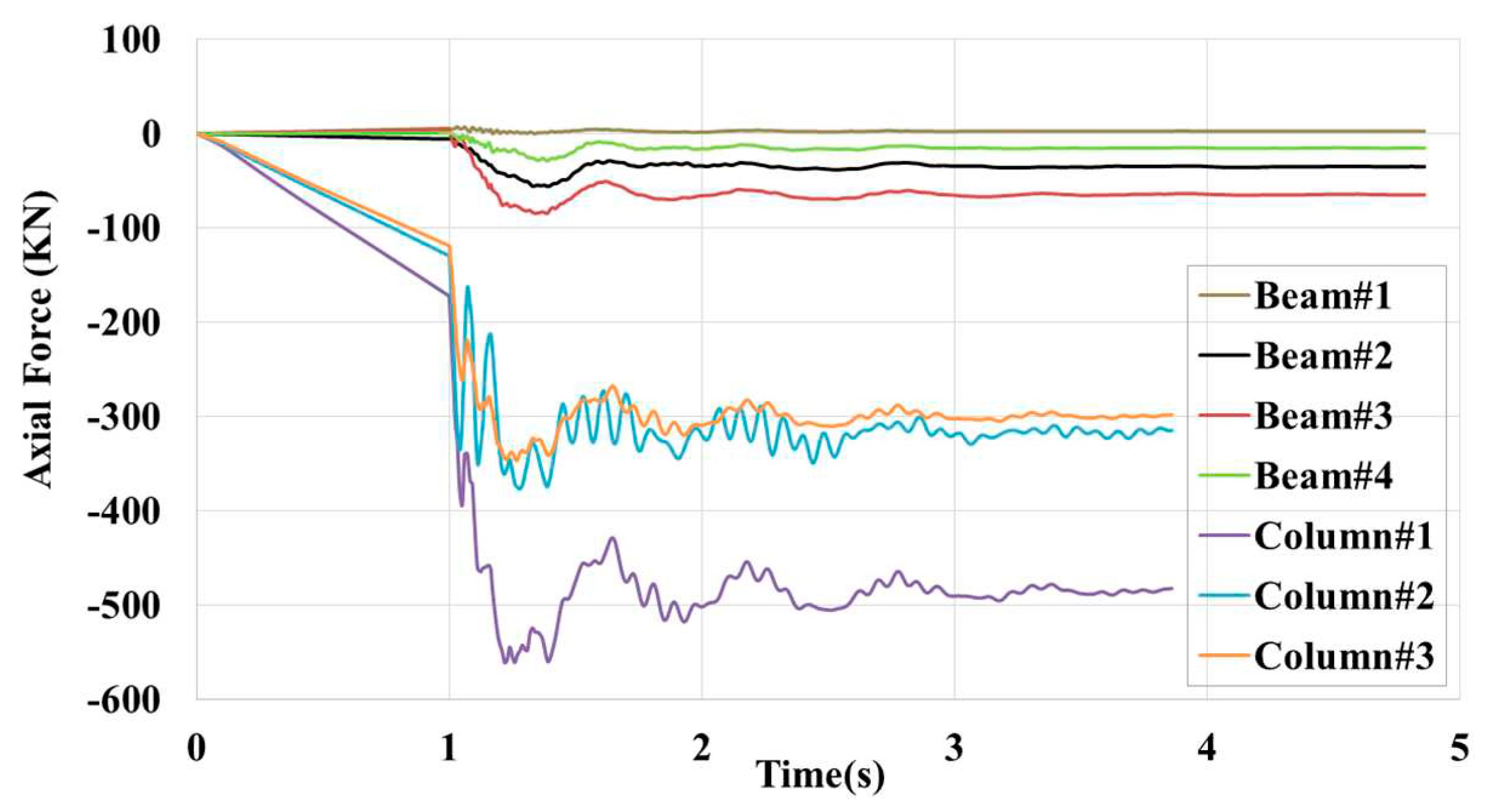
In this case, Column#1 carried the highest load, about 560kN, with a corresponding DSR=3.25 and DIF=1.15. The critical buckling load of columns was about 860kN. In the corner module removal scenario, Column#1 has a key role in the stability of the entire building because, as shown in
Figure 9, substantial load distribution occurs. The time history of axial load in beams shows that they are in compression and Beam#3 has the highest value. Additionally, it was observed that, despite the employing of plastic hinges in the finite element model of the MSBs, no plastic hinges formed. This aligns with the findings of the previous study [
28], which discussed that in the scenario of corner module removal in low-rise MSBs, the formation of plastic hinges can be disregarded as global column buckling is the dominant behaviour.
After removing the corner module, no inter-module connection failure is observed (see
Figure 10). As mentioned above the failure values for inter module connections are summarized in the
Table 1. The compressive force in VC#3 is similar to Column#1. HC#1 carries the highest shear force corresponding to DCR=160/2000=0.08, indicating that the redistributed load flows mainly in the X direction rather than Y.
4.2. 8-storey
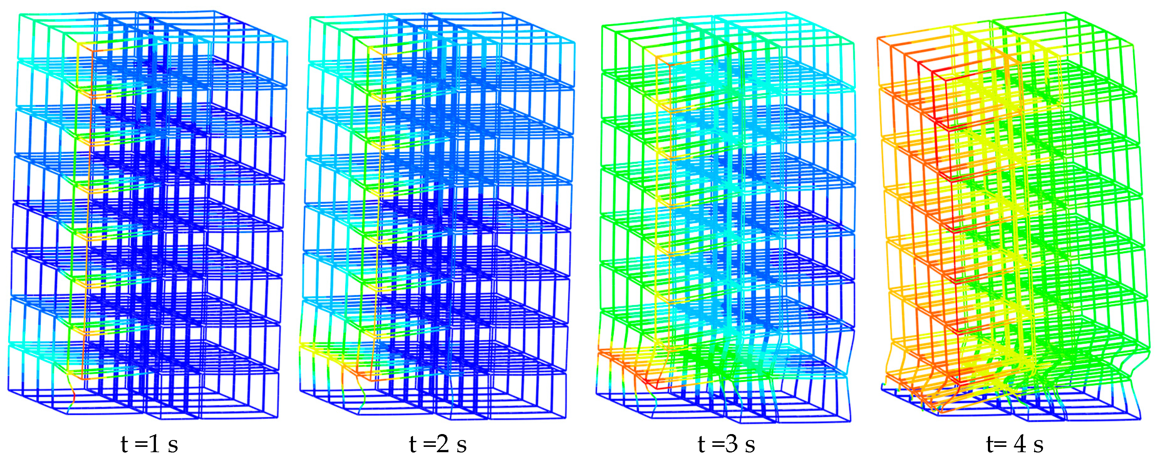
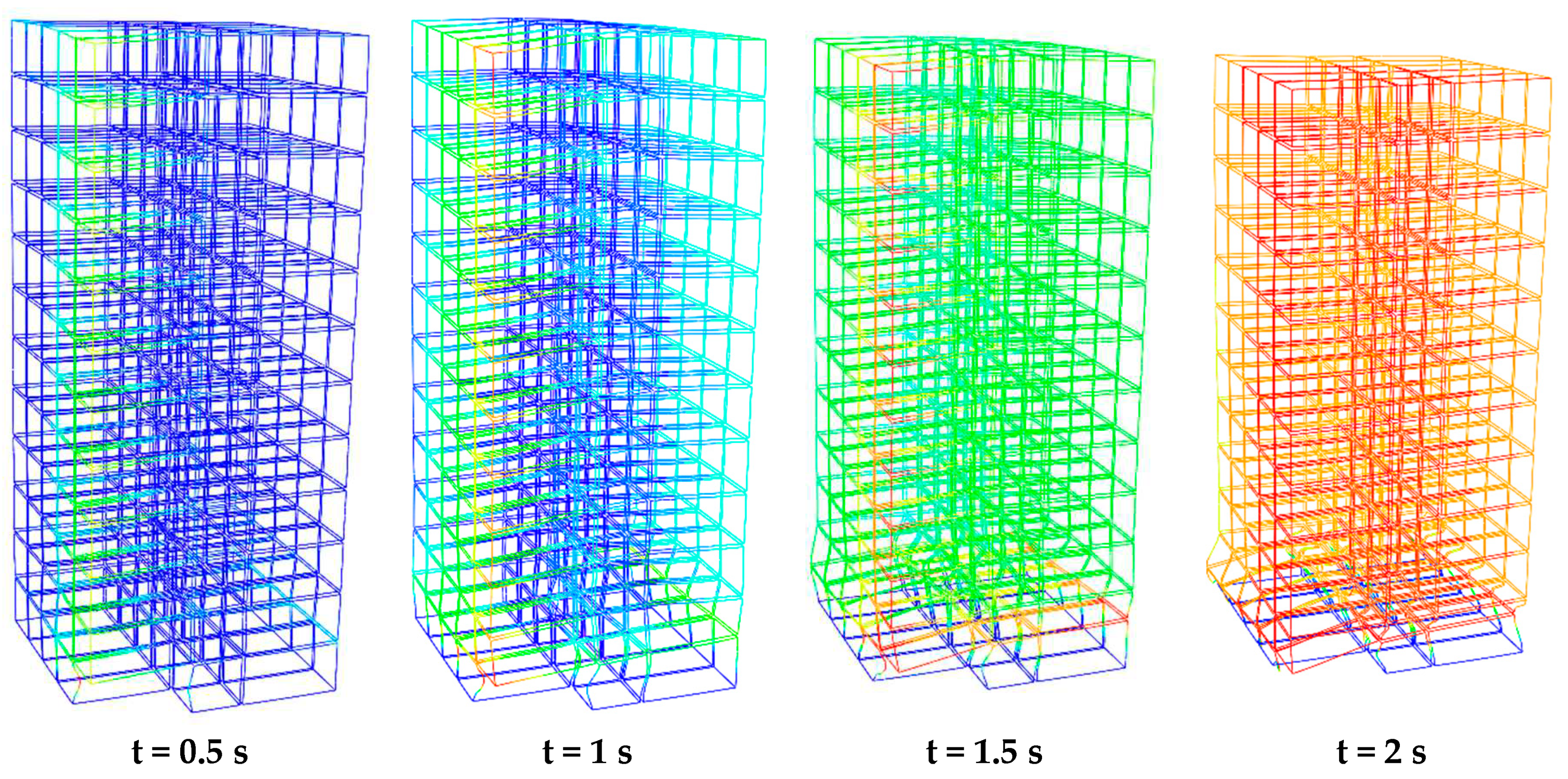
In the second case, the eight-story MSB was inadequate to maintain its robustness and collapsed. The collapse sequence of case no.2 is shown in
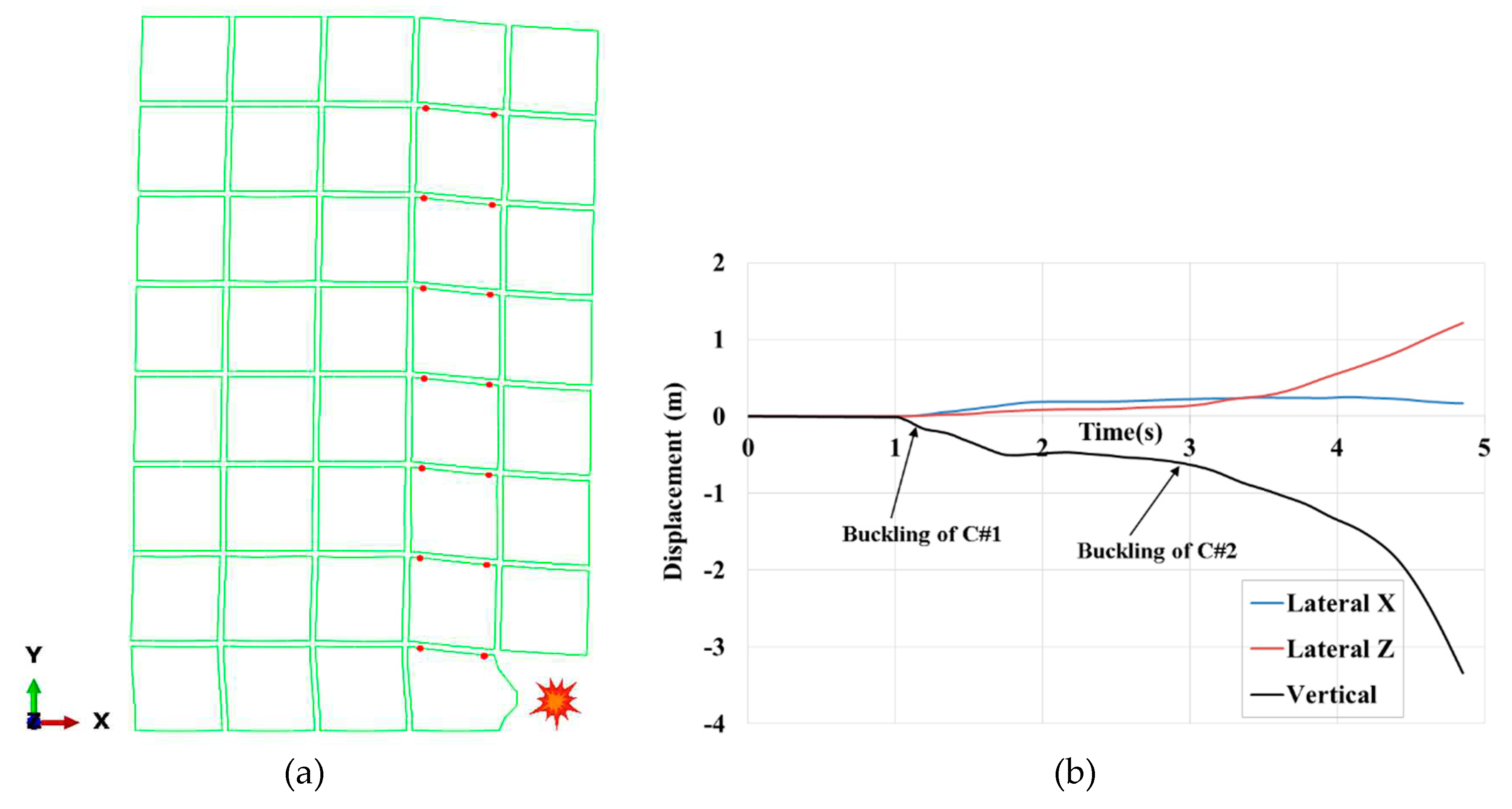
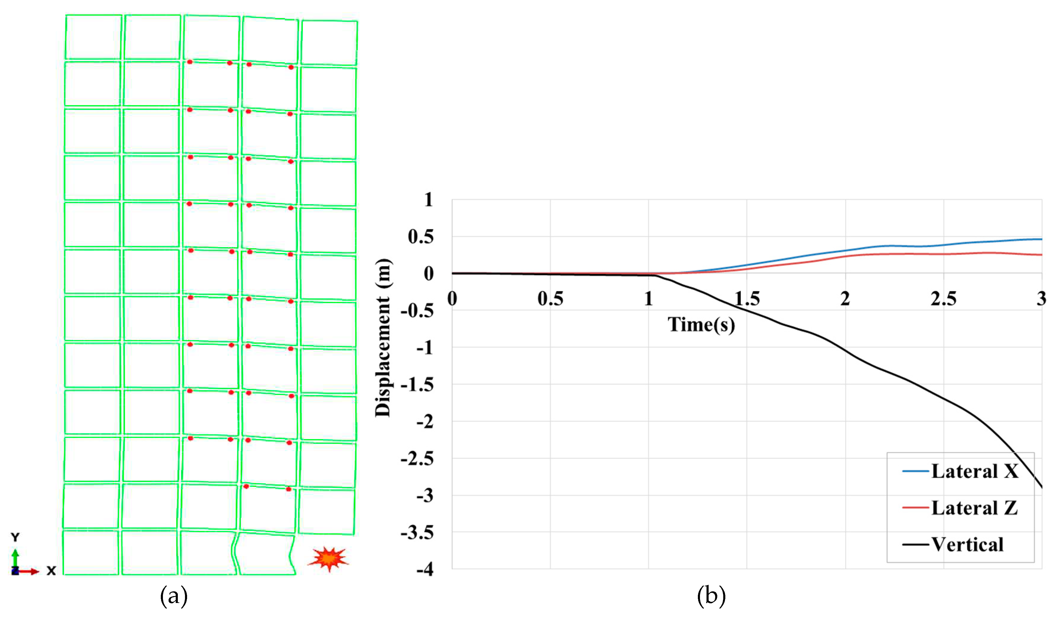
Figure 11. In the previous case, it was displayed that Colum#1 is very prone to buckling because of substantial load redistribution. Accordingly, in case no.2, the collapse was triggered by the buckling of Column#1 located close to the removed module and was accompanied with the buckling of column#2 after a while. As depicted in
Figure 12(b), after a second of removing the corner modules, the maximum vertical and lateral displacements are about 49cm and 20cm, respectively. Then, due to successive buckling of columns in the front row, the building tends to overturn around the X-axis.
The initial plastic hinges, which play an essential role in the robustness of the buildings, are shown in
Figure 12(a). The hinges are formed in the ceiling beams of the modules right close to the removed one because the rotation of these beams resulting from unsymmetrical deflection is more pronounced than those above the removed modules. After removing the corner modules, the main part of the gravity load tolerated by the removed columns is transferred to the column no.1. Moreover, the plastic hinge formation in the beams connected to the column no.1 increase the effective length factor, K, so that exacerbates the situation of the partially buckled column. The K-factors determining the effective length of columns in corner-supported steel modular buildings are investigated by Farajian et al. [44–46], with consideration for both sway and non-sway frames.
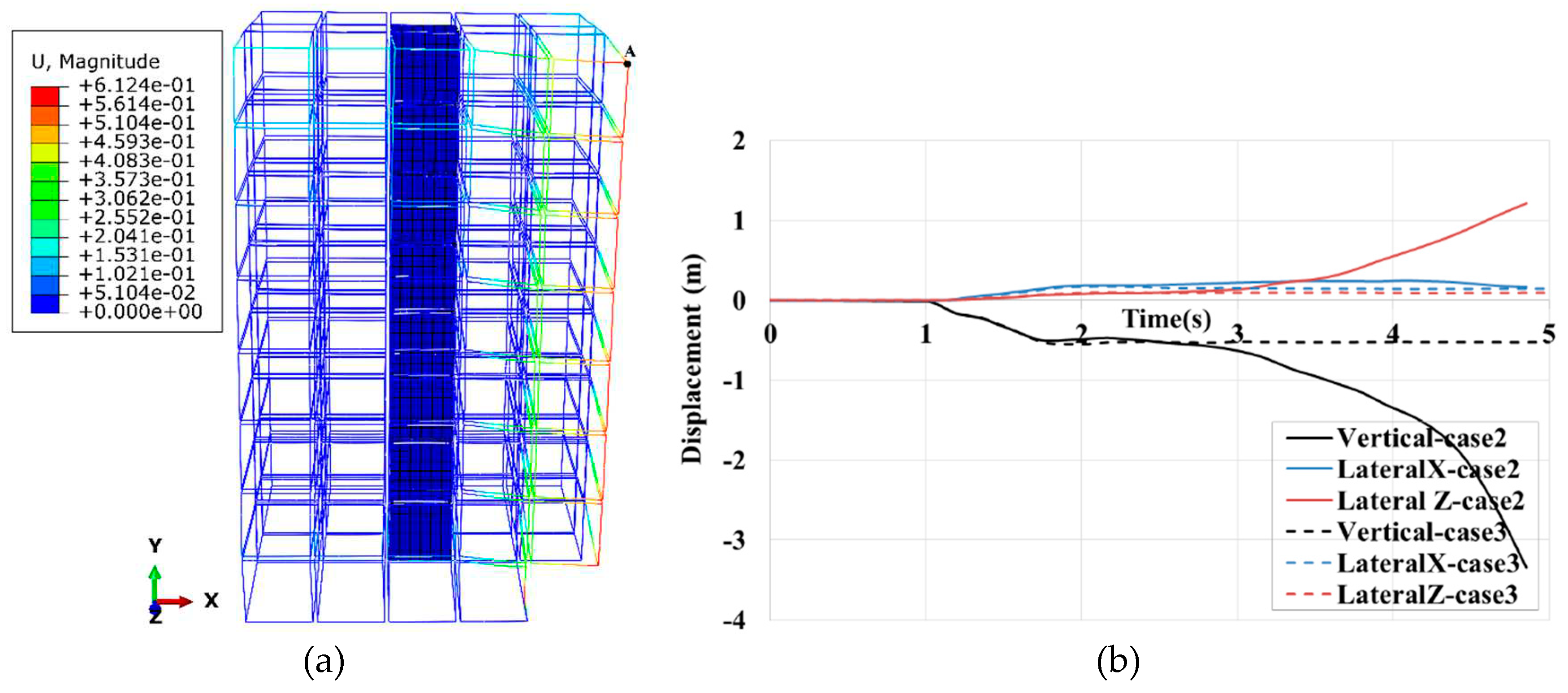
To explore the impact of the core wall on the collapse behaviour of MSB against corner module removal, the core wall system was installed in three zones (case no: 3-5), and their responses were compared with the bare frame (case no.2).
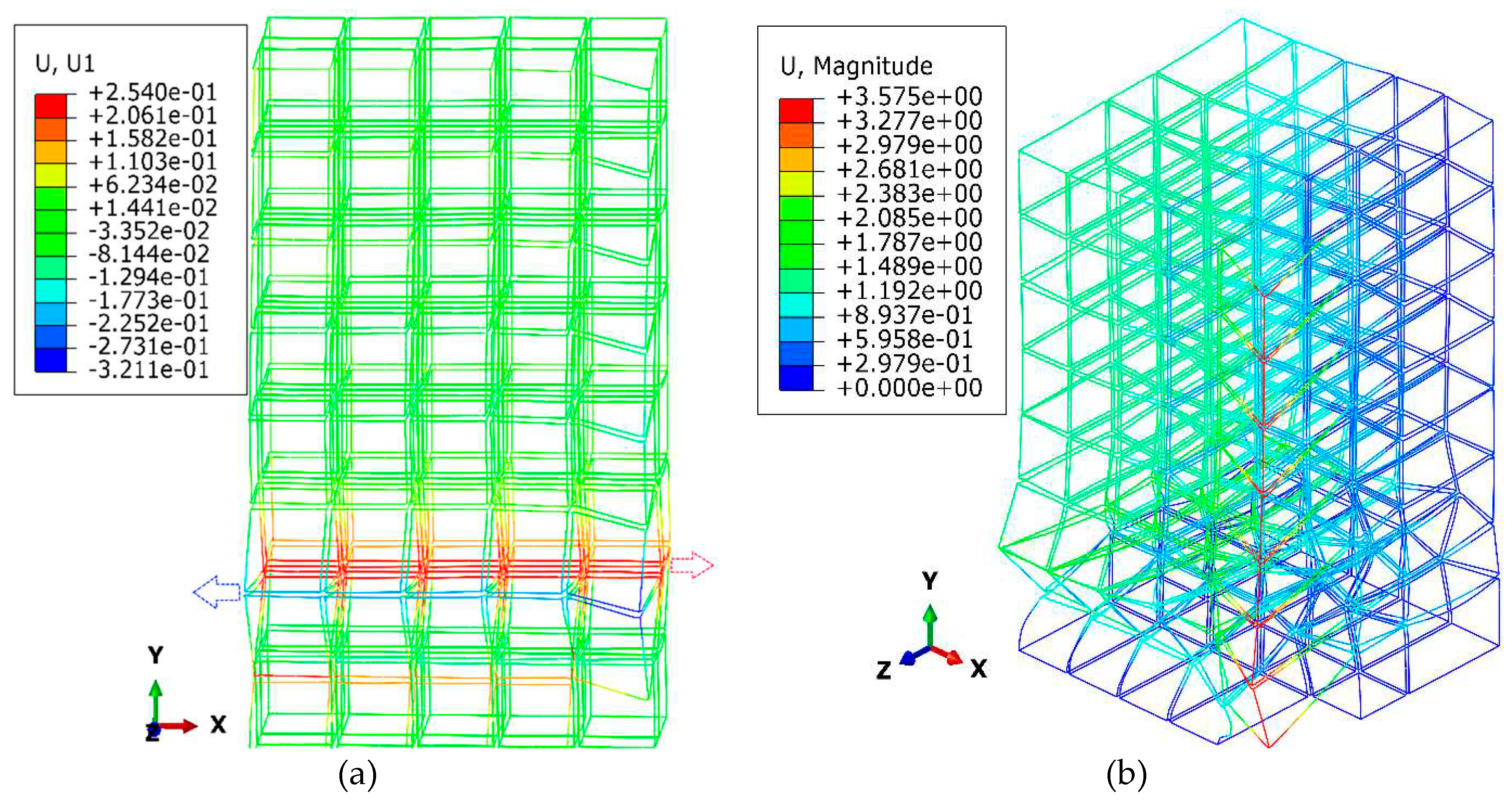
It was shown that the core wall located at the centre of the building (case no.3) arrested the collapse of the building under the corner module loss scenario. The lateral displacements in cases no.2 & 3 were approximately equal when the building was in a stable state. Despite the buckling of column#1 and significant vertical displacement of about 520 mm depicted in
Figure 13(a), the building maintains its robustness under dynamic loads. The time history of lateral and vertical displacements of the roof corner is shown in
Figure 13(b). The distribution of the first plastic hinges is the same as in case no.2.
The time history of axial forces in several beams and columns in case no.2 and case no.3 is compared in
Figure 14. In case no.2 the DSR of column#1 and column#2 are 2.87kN and 3.34kN, respectively. The highest load redistribution in column#2 for case no.3 and case no.2 is about 867kN and 993kN, respectively. In case no.3, where the core wall was cantered, beams experienced more fluctuation in their axial load immediately after module removal. The axial force in Beam#1 and Beam 2 was the opposite of each other. As Beam#2 was linked to HC#1 had to bear tensile load while Beam#1 suffered compressive load. In case no.3, after the buckling of Column#1 occurred, twice as many loads were redistributed in these beams compared to case no.2. It showed that the concrete core led to better load sharing through the beams in the vicinity of removed modules. Thus, the less axial load is redistributed to Column#2, as shown in
Figure 14(a). The maximum redistributed load in Column#2 is reduced by 12% compared with case no.2. In both cases no.2 and no.3, Column#1 carried a load of about 1100kN, which was higher than the buckling capacity.
Regarding inter-module connections, shown in
Figure 15, when column#2 buckles in case no.2 the load-bearing capacity of HC#2 tends to zero. Despite the high deformation of the building, no inter-module connection failure was observed because the dynamic redistribution in inter-module connections, especially HC#1, which was considered the most critical connection, was much lower than failure values. In both cases, The HC#1 maximum shear force was about 300kN with a DCR of 300/2000=0.15. The highest force redistribution through the inter-module connections was the axial force in VC#3, approximately equal to the buckling load in Column#1.
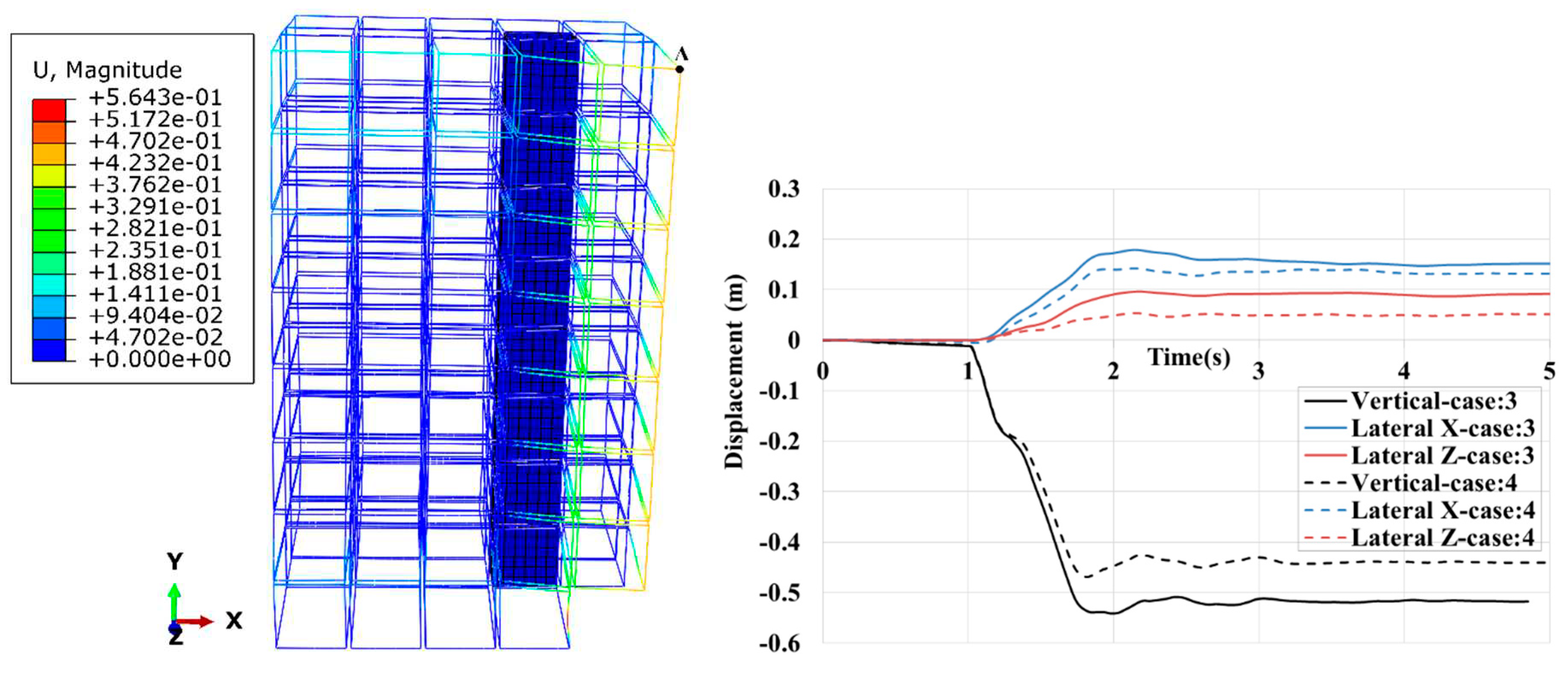
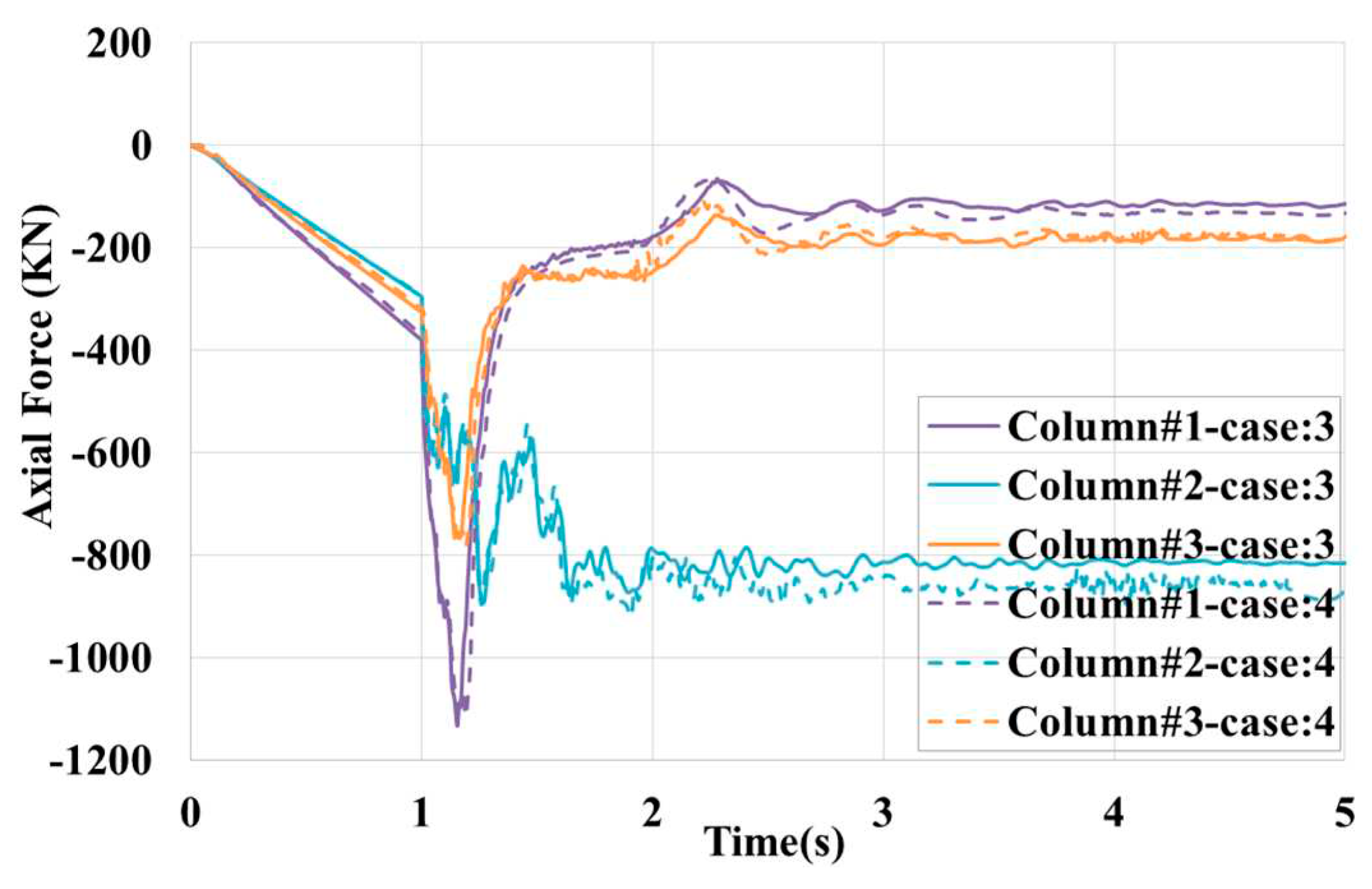
In the following, the outcomes of cases no. 4 & 5 are compared with case no.3. The results of case no.4 and case no.5 in terms of displacements, axial forces, and inter-module connection forces are very close to each other. However, the axial force in column#2 of case no.5 attached to shear walls was reduced by about 50% compared with case no.4. Contrary to case no.3, when the core wall was directly connected to the removal zone through inter-module connections, the shear wall reduced horizontal displacements, as observed in
Figure 16(b). The lateral Z displacement in case no.4 is about 50% lesser than in case no.3.
Figure 17 presents the time history of axial forces in the columns is virtually the same; however, the redistributed load for column#2 in case no.4 is a bit higher than in case no.3. Although the shear core did not reduce the redistributed load in column#2, the vertical displacement that the building undergoes is a little lesser than in case no.3. This is because of decreasing the horizontal displacements provided by the stiff core wall, connected directly to the modules above the missing modules. In fact, as illustrated, the horizontal displacements can accelerate the column’s buckling, and restraining them helps the building stay robust.
It can be seen from
Figure 18; that the tensile envelope contours are mostly appeared on the walls that are parallel to the X-direction. The maximum tensile stress is about 2.7 MPa, which is lower than the ultimate tensile strength of concrete. The majority of the envelope contour is located in the walls of the first four stories of MSB. Moreover, the bracing effect on these walls can be seen. Therefore, walls with less thickness or braces should be considered for upper levels. On the other hand, The Maximum compressive stress is just limited to the vicinity of columns.
4.3. 12-storey
In the sixth case, the 12-story MSB, considered as a high-rise building, collapses two seconds after removing the corner module. The collapse sequence of this case is shown in
Figure 19. Analogous to the 8-storey MSB, the collapse initiates with the buckling of columns #1 & #2 but continues with the buckling of the rest of the columns at the first and second storey simultaneously. In
Figure 19(b), after 0.5 seconds of removing the corner modules, the maximum vertical and lateral displacements are about 500 mm and 110mm, respectively. Then due to further column buckling at the front row, the building tends to overturn about the X-axis.
As shown in
Figure 20(a), the first set of plastic hinges formed in 0.6 seconds after the sudden removal of corner modules at the first elevation. Unlike the 8-story MSB, no hinges are observed at the first storey immediately after module removal. In addition, the hinges are extended to the center modules at the first elevation demonstrating more beams participated in load bearing.
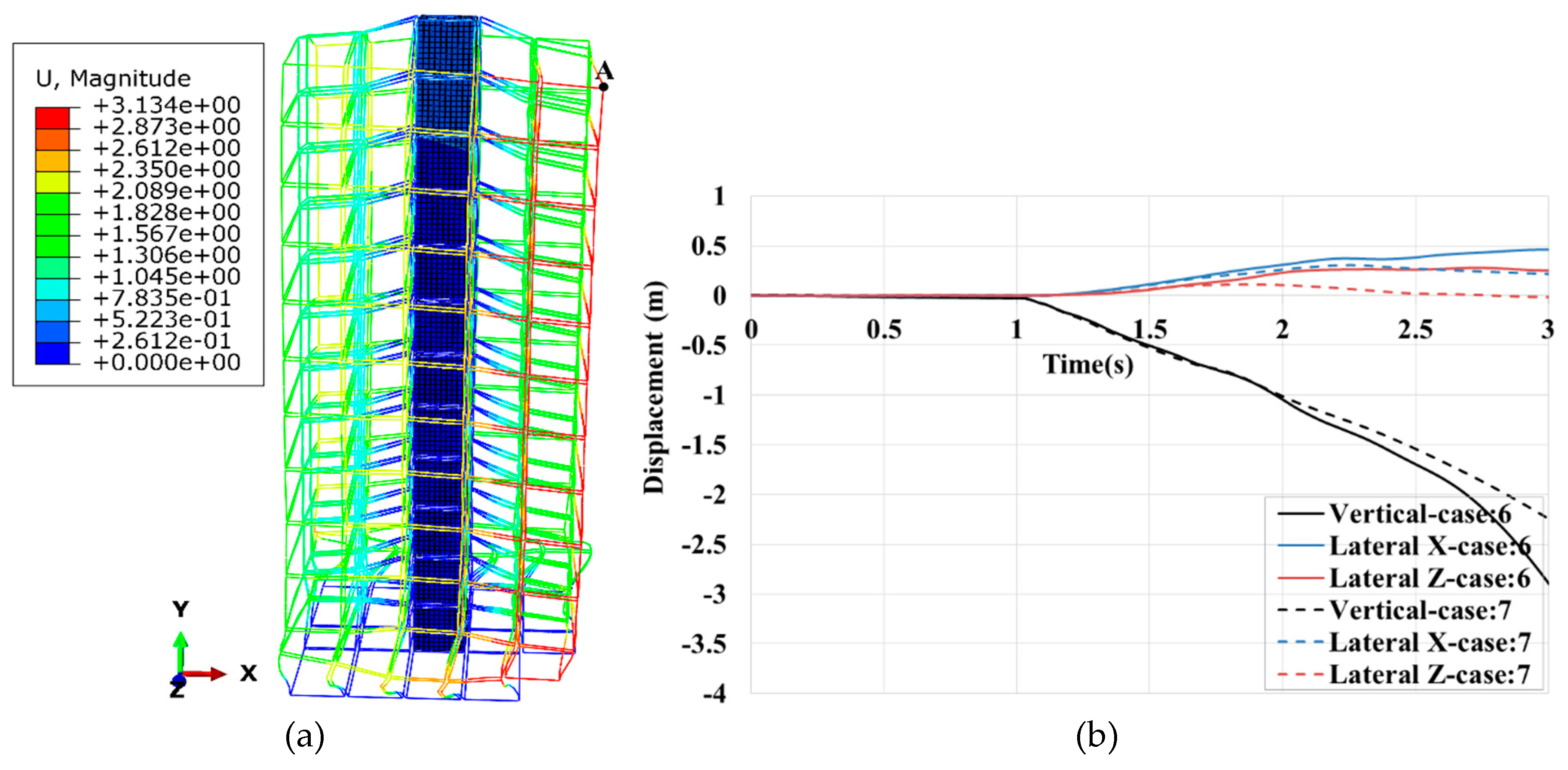
In the following, the effect of the shear wall (case no:7-9) on the collapse behaviour of a 12-storey MSB is studied. It is shown that the core wall system located at the center of the building (case no.7) does not prevent the building from collapsing. The time history of lateral and vertical displacements of the roof corner is shown in
Figure 21(b). The maximum lateral displacements at the beginning are about zero, eventually reaching about 500 mm. Similar to case no.6 (bare frame), the slope of the vertical displacement is constant because columns at the first and second floor buckle successively. The distribution of the first set of plastic hinges is the same as in case no.6.
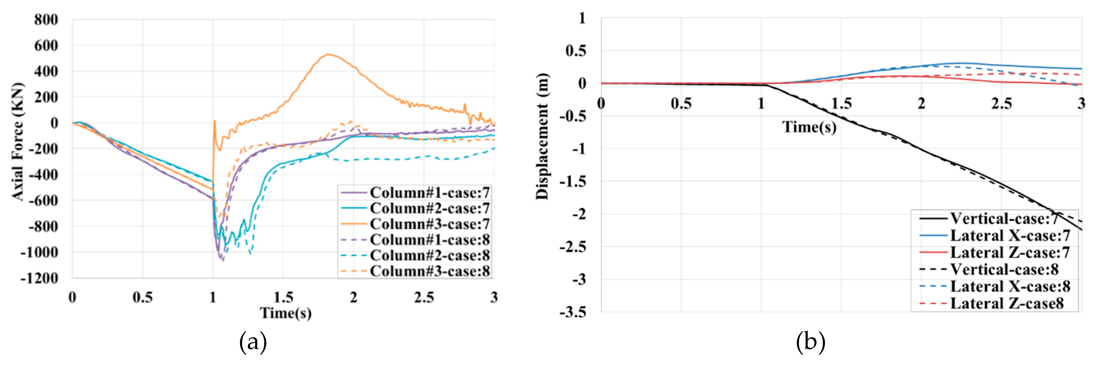
The time history of axial forces in several beams and columns in case no.6 and case no.7 is compared in
Figure 22. Like the previous cases, a part of the loads is redistributed by an additional load path, owing to the core wall, in beams #1 and #2. In both cases, the redistributed load in Column#2 and Column#1 is more than the critical buckling load, which is about 860kN, as shown in
Figure 22(a). In case no.6, Column#1 tolerates the highest load of about 1051kN with the corresponding DSR =1071/465=2.3.
As shown in
Figure 23, there is still a high level of strength reserve capacity in the inter-module connections. VC#3 suffers the maximum compressive force with corresponding DCR=1071/1700=0.63. In case no.7, the shear force in HC#1 increases to 500kN due to the buckling of a column close to Column#3 on the second floor.
As the result of case no.8 and case no.9 was approximately identical, case no.8 is compared with case no.7. The results, depicted in
Figure 24, in terms of displacements, axial forces, and inter-module connection forces are very close. In these cases, neither alternative loading paths due to the shear core nor limiting the lateral displacements help the building's robustness.
In terms of the concrete core’s stress pattern, like the 8-storey MSB, most envelope contour is located at the first half-height of the 12-storey MSB. The Maximum compressive stress is localized in the vicinity of columns, and The Maximum tensile stress is found in floor and ceiling beams. The maximum tensile stress is about 3.44 MPa, near the ultimate tensile strength of concrete, and the maximum compressive stress is about 12 MPa, which is much lower than its capacity.
In summary, the final state of each case against the corner module loss scenario is presented in
Table 3. In case no: 6-9, because many columns start buckling at the same time, the core wall cannot safeguard the building stability via improving load sharing or reducing lateral displacements.
Conclusion
The research was focused on studying the role of the concrete core wall in the robustness of MSBs against immediate corner module removal. The verified numerical finite element macro model of the building is simulated by incorporating material and geometric nonlinearities. The inter-module connections are modelled with nonlinear simplified springs, and the intra-module connections are assumed rigid. The dynamic responses, including lateral displacements, inter-module connection forces, and beam and column's internal forces, are reported for MSBs with different stories and shear core wall positions. In the end, parametric studies were undertaken, including stiffness softening of inter-module connections and intra-module rigidity. The main findings from this study are summarized as follows:
Unlike low-rise traditional steel buildings, 4-storey MSBs are robust against corner module removal. No columns buckle at the base level, and no plastic hinges appear in structural members. In addition, in the corner module removal scenario, Inter-module connections showed a significant safety factor in all cases, so no inter-module failure was observed.
In 12-MSBs, where many columns collapse simultaneously, the core wall has a minimal impact on robustness because there might not be enough time for load sharing. However, 8-MSBs benefited from the core wall system and maintained their robustness. The core wall helps the robustness of MSBs in two ways: The first is enhancing load sharing when the core is located at the centre (zone 1). The second is reducing lateral displacements, provided that the core wall is directly connected to the modules above the missing module (zone 2 or 3).
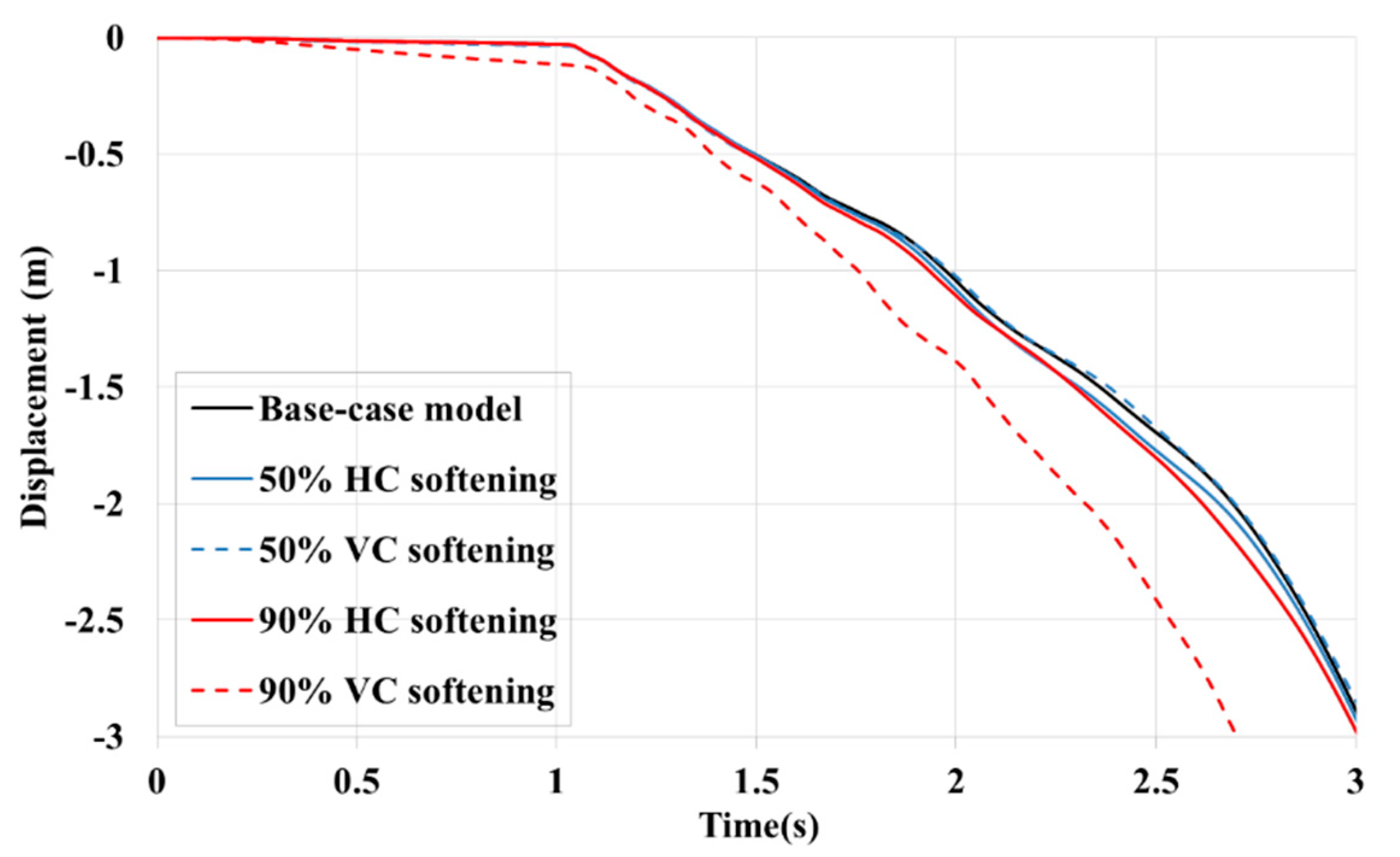
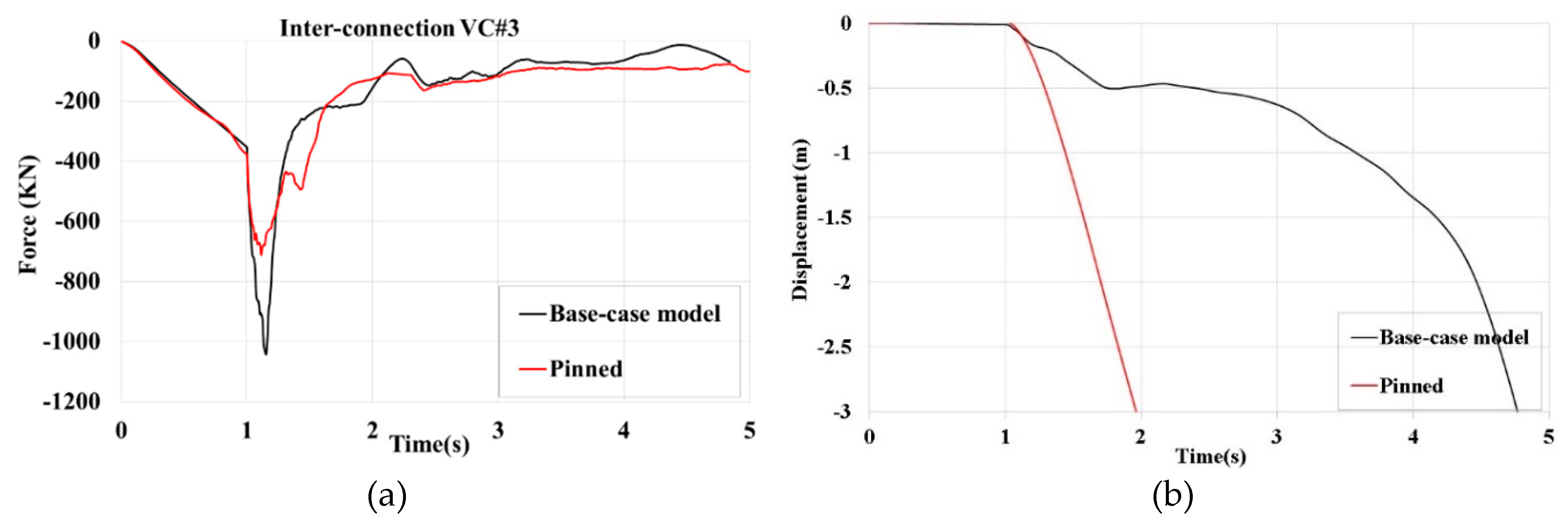
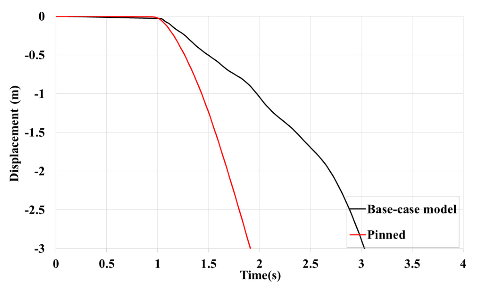
Softening Horizontal inter-module connections can worsen or improve the performance of the remaining modules against gravity-induced progressive collapse. In an 8-storey modular building, 50 % and 90% of softening in HCs accelerated and delayed the progressive collapse respectively by increasing flexibility. However, they were accompanied by many connection failures that led to the collapse of the whole building. Therefore, choosing an optimized inter-module connection stiffness is essential for the robustness of MSBs.
Preventing plastic hinges from forming can be considered as an anti-collapse mechanism. It turned the unstable bare-frame 8-storey MSB against the corner module removal scenario into a robust one.
In the corner-module removal scenario, the early set of plastic hinges formed in the ceiling beams of the first elevation (in the X-direction), which means structural members in this region have higher participation in carrying redistributed loads.
The progressive collapse of steel modular buildings with a shear core is simulated numerically using the finite element software Abaqus. Load redistribution and progressive collapse response of modular steel buildings (MSBs) with a typical layout under corner module loss scenario are investigated. Various modular building cases with three different heights and core wall locations are considered. Moreover, a parametric analysis is conducted to assess the impact of inter-module connection stiffness, intra-module connection rigidity, and plastic hinges on the robustness of the MSB under gravity loading.
The research can be expanded to include other types of layouts and configurations such as different module sizes, geometries, material properties and collapse scenarios. Furthermore, the assumed instantaneous removal time, representing a blast scenario, can be adjusted to a longer duration, which is more representative of a fire scenario.
Figure 1.
A typical view of MSB with: (a) inter-module connection; (b) intra-module connection.
Figure 1.
A typical view of MSB with: (a) inter-module connection; (b) intra-module connection.
Figure 2.
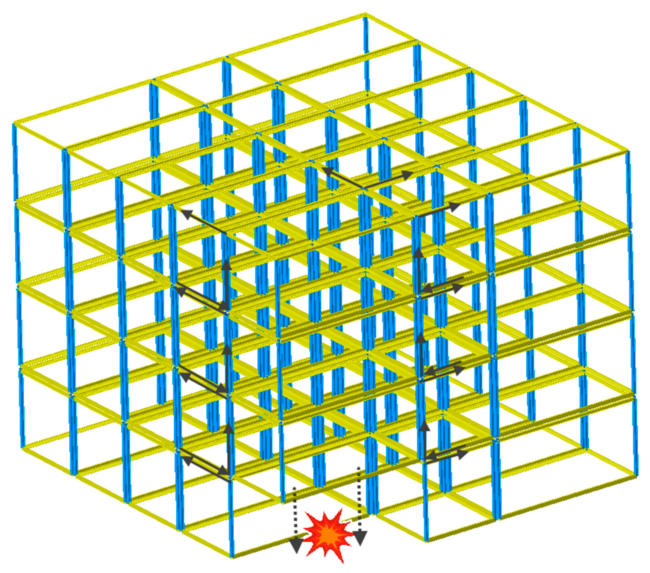
ALPs in an MSB under corner module loss scenario.
Figure 2.
ALPs in an MSB under corner module loss scenario.
Figure 3.
(a) Typical building plan; (b) Typical elevation view.
Figure 3.
(a) Typical building plan; (b) Typical elevation view.
Figure 4.
3D finite element model of the building.
Figure 4.
3D finite element model of the building.
Figure 5.
3D finite element model of the building.
Figure 5.
3D finite element model of the building.
Figure 6.
Comparison of dynamic displacement: the present study's results with those reported by Luo et al. [
24].
Figure 6.
Comparison of dynamic displacement: the present study's results with those reported by Luo et al. [
24].
Figure 7.
Typical critical connections and elements.
Figure 7.
Typical critical connections and elements.
Figure 8.
(a) The final equilibrium position of the structure after corner module removal. (b) Time history of global displacements of the roof corner above the missing module, designated by A.
Figure 8.
(a) The final equilibrium position of the structure after corner module removal. (b) Time history of global displacements of the roof corner above the missing module, designated by A.
Figure 9.
Time history of axial forces in some beams and columns close to the missing module.
Figure 9.
Time history of axial forces in some beams and columns close to the missing module.
Figure 10.
Time history of the axial and shear forces in some critical HCs and VCs.
Figure 10.
Time history of the axial and shear forces in some critical HCs and VCs.
Figure 11.
Deformation of the case no.2 in different time frames after sudden removal of corner module.
Figure 11.
Deformation of the case no.2 in different time frames after sudden removal of corner module.
Figure 12.
(a) Distribution of plastic hinges at elevation:1, in 0.4s after the sudden removal of corner module. (b) Time history of global displacements of the roof corner above the missing module.
Figure 12.
(a) Distribution of plastic hinges at elevation:1, in 0.4s after the sudden removal of corner module. (b) Time history of global displacements of the roof corner above the missing module.
Figure 13.
(a) The final equilibrium position of the structure after corner module removal. (b) Time history of global displacements of the roof corner above the missing module, designated by A.
Figure 13.
(a) The final equilibrium position of the structure after corner module removal. (b) Time history of global displacements of the roof corner above the missing module, designated by A.
Figure 14.
Time history of axial forces in some (a) columns and (b) beams, close to the missing module.
Figure 14.
Time history of axial forces in some (a) columns and (b) beams, close to the missing module.
Figure 15.
Time history of the axial and shear forces in some critical HCs and VCs.
Figure 15.
Time history of the axial and shear forces in some critical HCs and VCs.
Figure 16.
(a) The final equilibrium position of the structure after corner module removal. (b) Time history of global displacements of the roof corner above the missing module, designated by A.
Figure 16.
(a) The final equilibrium position of the structure after corner module removal. (b) Time history of global displacements of the roof corner above the missing module, designated by A.
Figure 17.
Time history of axial forces in some columns.
Figure 17.
Time history of axial forces in some columns.
Figure 18.
Envelope contours of: (a) maximum principal (tensile) and (b) minimum principal (compressive) stress of the shear core located at zone 1.
Figure 18.
Envelope contours of: (a) maximum principal (tensile) and (b) minimum principal (compressive) stress of the shear core located at zone 1.
Figure 19.
Deformation of the case no.6 in different time frames after the sudden removal of the corner module.
Figure 19.
Deformation of the case no.6 in different time frames after the sudden removal of the corner module.
Figure 20.
(a) Distribution of plastic hinges at elevation (1), in 0.6s after sudden removal of corner module. (b) Time history of global displacements of the roof corner above the missing module.
Figure 20.
(a) Distribution of plastic hinges at elevation (1), in 0.6s after sudden removal of corner module. (b) Time history of global displacements of the roof corner above the missing module.
Figure 21.
(a) The collapse mode of the structure after corner module removal. (b) Time history of global displacements of the roof corner above the missing module, designated by A.
Figure 21.
(a) The collapse mode of the structure after corner module removal. (b) Time history of global displacements of the roof corner above the missing module, designated by A.
Figure 22.
Time history of axial forces in some a) columns and b) beams, close to the missing module.
Figure 22.
Time history of axial forces in some a) columns and b) beams, close to the missing module.
Figure 23.
Time history of the axial and shear forces in some critical HCs and VCs.
Figure 23.
Time history of the axial and shear forces in some critical HCs and VCs.
Figure 24.
(a) Time history of axial forces in some columns. (b) Time history of global displacements of the roof corner above the missing module, designated by A.
Figure 24.
(a) Time history of axial forces in some columns. (b) Time history of global displacements of the roof corner above the missing module, designated by A.
Figure 25.
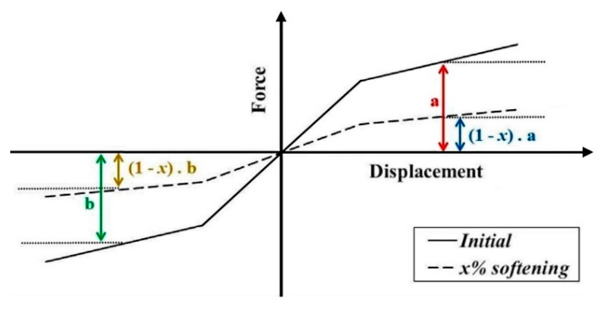
Softening of a typical connection’s spring.
Figure 25.
Softening of a typical connection’s spring.
Figure 26.
Time history of vertical displacements of the roof corner above the missing module, designated by A.
Figure 26.
Time history of vertical displacements of the roof corner above the missing module, designated by A.
Figure 27.
Comparison of the responses of the base case-model, and 50% and %90 softened springs.
Figure 27.
Comparison of the responses of the base case-model, and 50% and %90 softened springs.
Figure 28.
Sequence of the early set of inter-module connection failure for (a) 90% VC softening; (b) 90% HC softening.
Figure 28.
Sequence of the early set of inter-module connection failure for (a) 90% VC softening; (b) 90% HC softening.
Figure 29.
Time history of vertical displacements of the roof corner above the missing module, designated by A.
Figure 29.
Time history of vertical displacements of the roof corner above the missing module, designated by A.
Figure 30.
(a) The final equilibrium position of the structure after corner module removal. (b) Time history of global displacements of the roof corner above the missing module, designated by A.
Figure 30.
(a) The final equilibrium position of the structure after corner module removal. (b) Time history of global displacements of the roof corner above the missing module, designated by A.
Figure 31.
(a) The position of the structure at a) 0.5s and (b) 2s after corner module removal.
Figure 31.
(a) The position of the structure at a) 0.5s and (b) 2s after corner module removal.
Figure 32.
(a) Time history of axial forces in VC#3. (b) Time history of global displacements of the roof corner above the missing module, designated by A.
Figure 32.
(a) Time history of axial forces in VC#3. (b) Time history of global displacements of the roof corner above the missing module, designated by A.
Figure 33.
Time history of global displacements of the roof corner above the missing module, designated by A.
Figure 33.
Time history of global displacements of the roof corner above the missing module, designated by A.
Table 1.
Failure limits of inter-module connections.
Table 1.
Failure limits of inter-module connections.
| Connection |
Axial failure force |
Shear failure force |
| Vertical (VC) |
1700 KN |
2000 KN |
| Horizontal (HC) |
1200 KN |
2000 KN |
Table 2.
Overview of collapse analysis cases and corresponding building configurations.
Table 2.
Overview of collapse analysis cases and corresponding building configurations.
| Case No. |
Story No. |
Building frame types |
| 1 |
4 |
Bare frame (4s) |
| 2 |
8 |
Bare frame (8s) |
| 3 |
8 |
Bare frame + shear core at zone 1 (8 sw1) |
| 4 |
8 |
Bare frame + shear core at zone 2 (8 sw2) |
| 5 |
8 |
Bare frame + shear core at zone 3 (8 sw3) |
| 6 |
12 |
Bare frame (12s) |
| 7 |
12 |
Bare frame + shear core at zone 1 (12 sw1) |
| 8 |
12 |
Bare frame + shear core at zone 2 (12 sw2) |
| 9 |
12 |
Bare frame + shear core at zone 3 (12 sw3) |
Table 3.
Summary of building's stability results.
Table 3.
Summary of building's stability results.
| Cases |
Stability State |
Main Reasons |
| 1) 4s |
stable |
No column buckling |
| 2) 8s |
collapsed |
Buckling C#1 and C#2 |
| 3) 8 sw1 |
stable |
Less redistributed load in C#2 |
| 4) 8 sw2 |
stable |
Less lateral displacements |
| 5) 8 sw3 |
stable |
C#2 constrained with concrete core |
| 6) 12s |
collapsed |
Several columns buckling |
| 7) 12 sw1 |
collapsed |
Several columns buckling |
| 8) 12 sw2 |
collapsed |
Several columns buckling |
| 9) 12 sw3 |
collapsed |
Several columns buckling |
