Submitted:
11 January 2024
Posted:
11 January 2024
You are already at the latest version
Abstract
Keywords:
1. Introduction
2. Materials and Methods
2.1. Materials and reagents
2.2. Synthesis of hybrid materials
2.3. Characterization of hybrid materials
2.4. Procedures for manufacturing the modified electrodes
2.5. Electrochemical experiments
3. Results and discussion
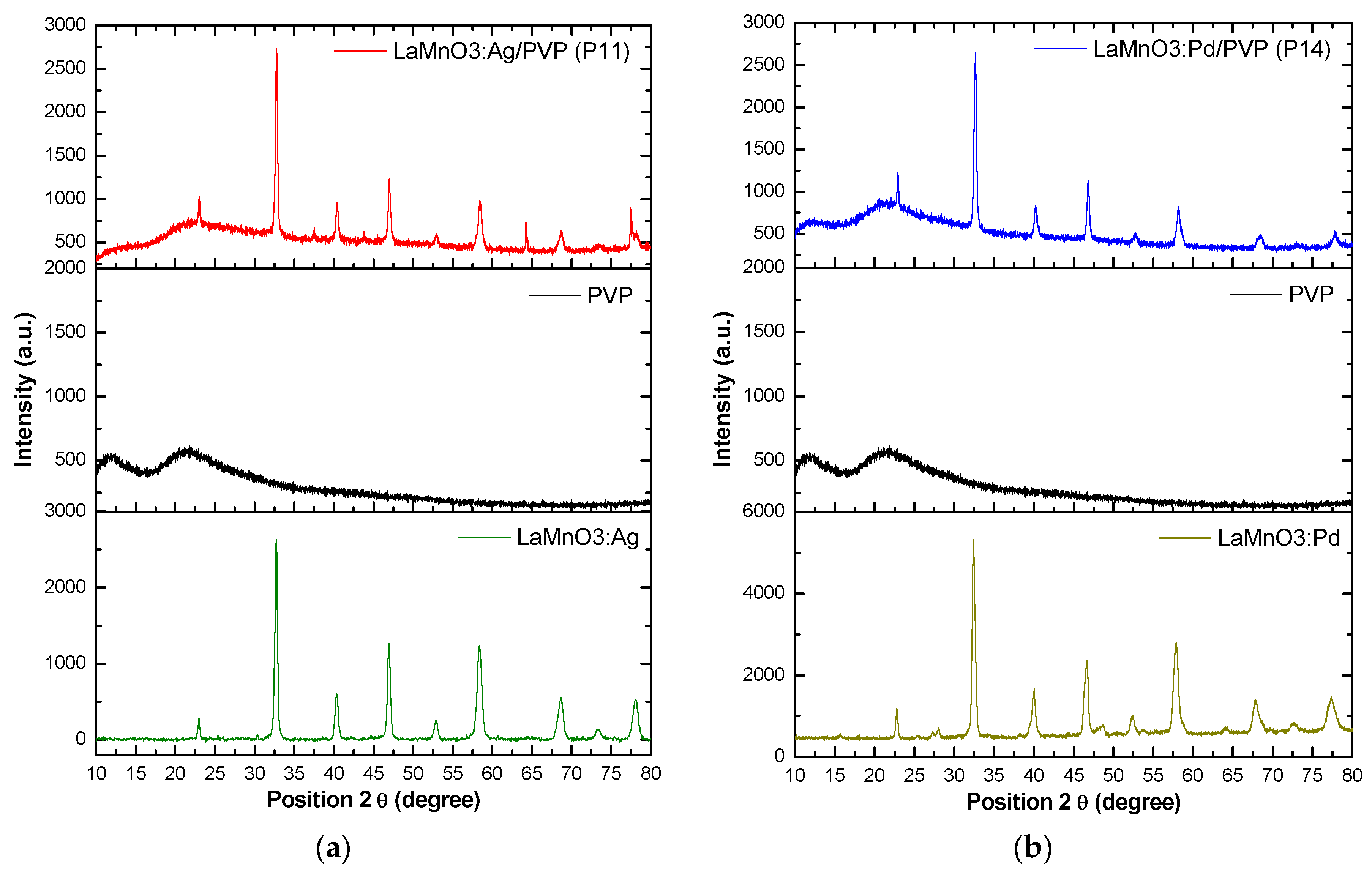
3.1. XRD analysis
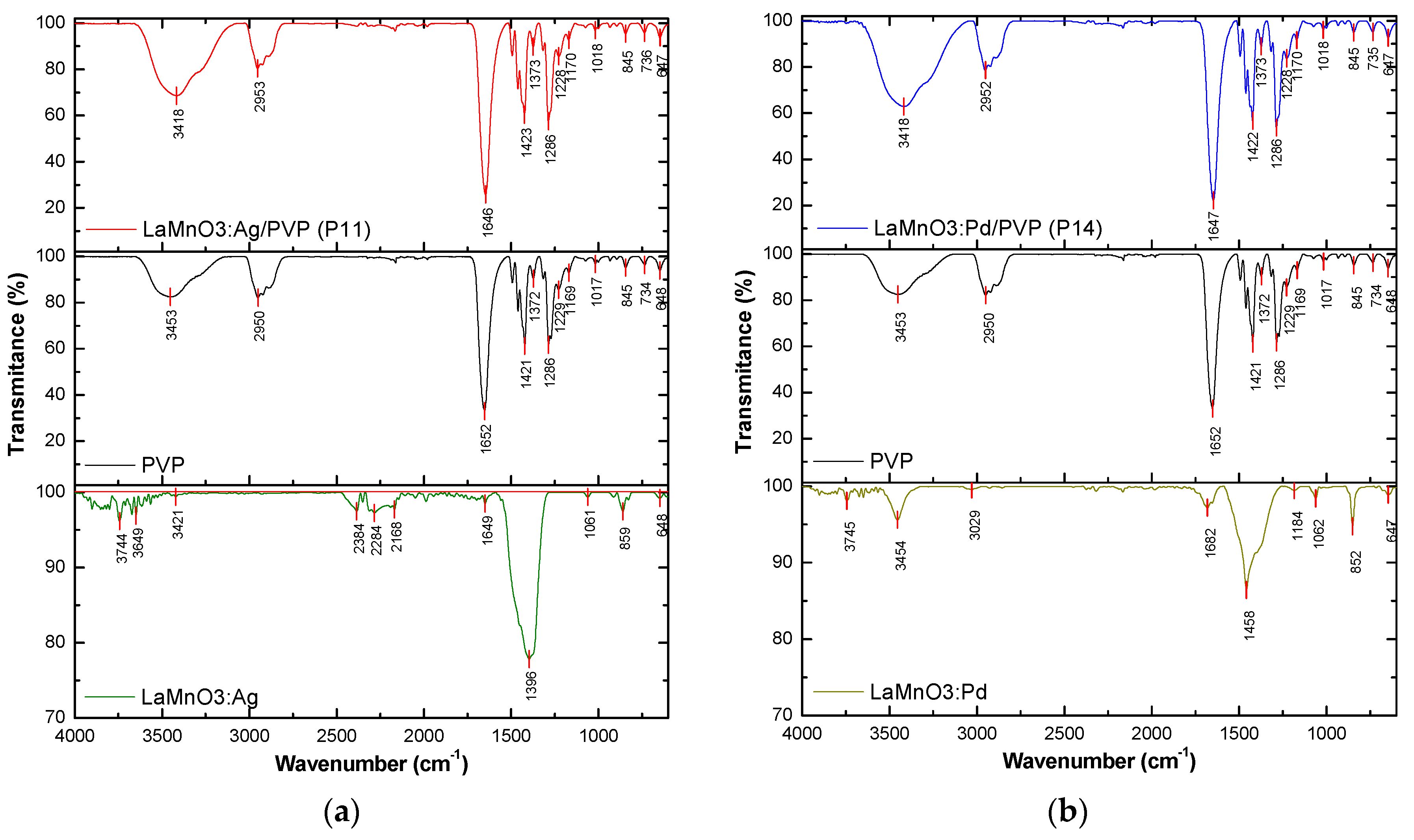
3.2. FT-IR analysis
3.3. SEM micrographs
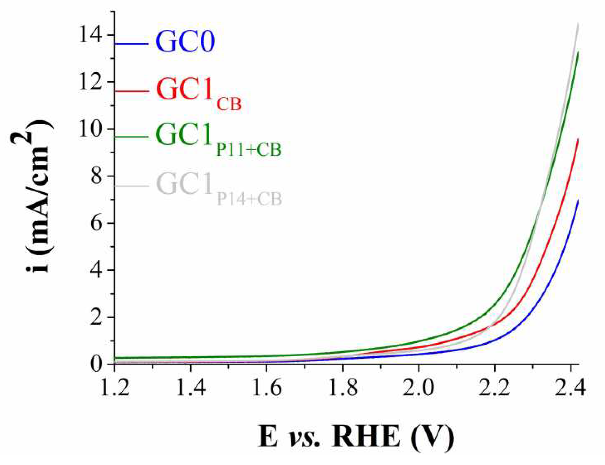
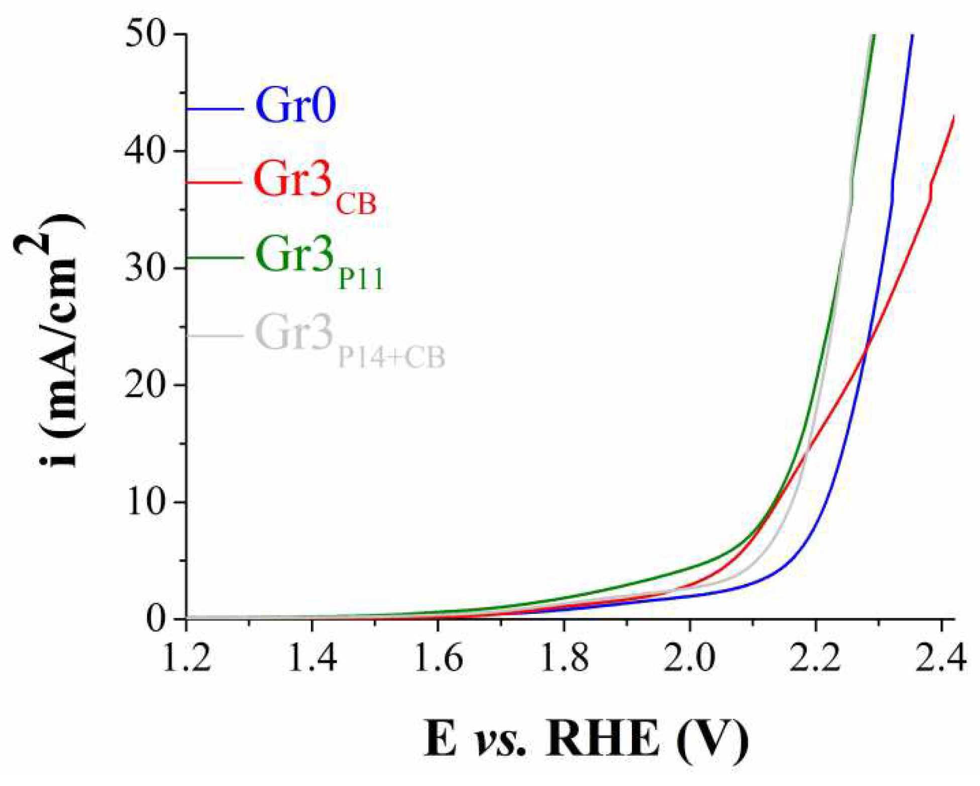
3.4. Electrochemical experiments
3.5. Further considerations
4. Conclusions
Author Contributions
Funding
Data Availability Statement
Acknowledgments
Conflicts of Interest
References
- Brahmi, C.; Benltifa, M.; Vaulot, C.; Michelin, L.; Dumur, F.; Airoudj, A.; Morlet-Savary, F.; Raveau, B.; Bousselmi, L.; Lalevée, J. New hybrid perovskites/polymer composites for the photodegradation of organic dyes. Eur. Polym. J. 2021, 157, 110641. [Google Scholar] [CrossRef]
- Al-Muntaser, A.A.; Pashameah, R.A.; Sharma, K.; Alzahrani, E.; Hameed, S.T.; Morsi, M.A. Boosting of structural, optical, and dielectric properties of PVA/CMC polymer blend using SrTiO3 perovskite nanoparticles for advanced optoelectronic applications. Opt. Mater. 2022, 132, 112799. [Google Scholar] [CrossRef]
- Basturk, S.B.; Dancer, C.E.J.; McNally, T. Fabrication and Characterization of Composites of a Perovskite and Polymers with High Dielectric Permittivity. Mater. Res. Bull. 2021, 135, 111126. [Google Scholar] [CrossRef]
- Koczkur, K.M.; Mourdikoudis, S.; Polavarapu, L.; Skrabalak, S.E. Polyvinylpyrrolidone (PVP) in nanoparticle synthesis. Dalton Trans. 2015, 44, 17883. [Google Scholar] [CrossRef]
- Voronova, M.I.; Surov, O.V.; Rubleva, N.V.; Kochkina, N.E.; Afineevskii, A.V.; Zakharov, A.G. Nanocrystalline cellulose composites with polyvinylpyrrolidone: Selfassembly and dispersibility in water. Compos. Commun. 2019, 15, 108–112. [Google Scholar] [CrossRef]
- Ahmad, F.; Rafiq, K.; Najam, T.; Hussain, E.; Sohail, M.; Abid, M.Z.; Mahmood, A.; Javed, M.S.; Shah, S.S.A. Metal-organic frameworks for electrocatalytic water-splitting: Beyond the pyrolysis. Int. J. Hydrog. Energy 2023, 48, 35075–35111. [Google Scholar] [CrossRef]
- Roy, S.; Huang, Z.; Bhunia, A.; Castner, A.; Gupta, A.K.; Zou, X.; Ott, S. Electrocatalytic hydrogen evolution from a cobaloxime-based metal−organic framework thin film. J. Am. Chem. Soc. 2019, 141, 15942–15950. [Google Scholar] [CrossRef]
- Hosseini, S.E. Fossil fuel crisis and global warming. In Fundamentals of low emission flameless combustion and its applications; Hosseini, S.E., Ed.; Academic Press: 125 London Wall, London, United Kingdom, 2022; pp. 1–11. [Google Scholar]
- Lanjekar, P.R.; Panwar, N.L.; Agrawa, C. A comprehensive review on hydrogen production through thermochemical conversion of biomass for energy security. Bioresour. Technol. Rep. 2023, 21, 101293. [Google Scholar] [CrossRef]
- Bulfin, B.; Carmo, M.; Van de Krol, R.; Mougin, J.; Ayers, K.; Gross, K.J.; Marina, O.A.; Roberts, G.M.; Stechel, E.B.; Xiang, C. Editorial: Advanced water splitting technologies development: Best practices and protocols. Front. Energy Res. 2023, 11, 1–4. [Google Scholar] [CrossRef]
- Peng, Y.; Jiang, K.; Hill, W.; Lu, Z.; Yao, H.; Wang, H. Large-scale, low-cost, and high-efficiency water-splitting system for clean H2 generation. ACS Appl. Mater. Interfaces 2019, 11, 3971–3977. [Google Scholar] [CrossRef]
- Son, M.-K. Design and demonstration of large scale Cu2O photocathodes with metal grid structure for photoelectrochemical water splitting. Energies, 2021, 14, 7422. [Google Scholar] [CrossRef]
- Xu, X.; Sun, H.; Jiang, S.P.; Shao, Z. Modulating metal–organic frameworks for catalyzing acidic oxygen evolution for proton exchange membrane water electrolysis. Sus. Mat. 2021, 1, 460–481. [Google Scholar] [CrossRef]
- Wang, S.; Lu, A.; Zhong, C.-J. Hydrogen production from water electrolysis: role of catalysts. Nano Converg. 2021, 8, 4. [Google Scholar] [CrossRef]
- Guo, F.; Macdonald, T.J.; Sobrido, A.J.; Liu, L.; Feng, J.; He, G. Recent advances in ultralow-Pt-loading electrocatalysts for the efficient hydrogen evolution. Adv. Sci. 2023, 10, 2301098. [Google Scholar] [CrossRef]
- Sun, H.; Jung, W.C. Recent advances in doped ruthenium oxides as high-efficiency electrocatalysts for the oxygen evolution reaction. J. Mater. Chem. A 2021, 9, 15506–15521. [Google Scholar] [CrossRef]
- Galyamin, D.; Tolosana-Moranchel, A.; Retuerto, M.; Rojas, S. Unraveling the most relevant features for the design of iridium mixed oxides with high activity and durability for the oxygen evolution reaction in acidic media. JACS Au 2023, 3, 2336–2355. [Google Scholar] [CrossRef] [PubMed]
- Niu, H.; Wang, Q.; Huang, C.; Zhang, M.; Yan, Y.; Liu, T.; Zhou, W. Noble metal-based heterogeneous catalysts for electrochemical hydrogen evolution reaction. Appl. Sci. 2023, 13, 2177. [Google Scholar] [CrossRef]
- Li, X.-P.; Huang, C.; Han, W.-K.; Ouyang, T.; Liu, Z.-Q. Transition metal-based electrocatalysts for overall water splitting. Chin. Chem. Lett. 2021, 32, 2597–2616. [Google Scholar] [CrossRef]
- Taranu, B.-O.; Fagadar-Cosma, E. Catalytic properties of free-base porphyrin modified graphite electrodes for electrochemical water splitting in alkaline medium. Processes 2022, 10, 611. [Google Scholar] [CrossRef]
- Alom, S.; Kananke-Gamage, C.C.W.; Ramezanipour, F. Perovskite oxides as electrocatalysts for hydrogen evolution reaction. ACS Omega 2022, 7, 7444–7451. [Google Scholar] [CrossRef]
- Wang, Y.; Wang, L.; Zhang, K.; Xu, J.; Wu, Q.; Xie, Z.; An, W.; Liang, X.; Zou, X. Electrocatalytic water splitting over perovskite oxide catalysts. Chinese J. Catal. 2023, 50, 109–125. [Google Scholar] [CrossRef]
- Rahman, S.; Hussain, A.; Noreen, S.; Bibi, N.; Arshad, S.; Rehman, J.U.; Tahir, M.B. Structural, electronic, optical and mechanical properties of oxide-based perovskite ABO3 (A = Cu, Nd and B = Sn, Sc): A DFT study. J. Solid State Chem. 2023, 317, 123650. [Google Scholar] [CrossRef]
- Taranu, B.-O.; Vlazan, P.; Svera, P.; Poienar, M.; Sfirloaga, P. New functional hybrid materials based on clay minerals for enhanced electrocatalytic activity. J. Alloys Compd. 2022, 892, 162239. [Google Scholar] [CrossRef]
- Sfirloaga, P.; Taranu, B.-O.; Poienar, M.; Vlazan, P. Addressing electrocatalytic activity of metal-substituted lanthanum manganite for the hydrogen evolution reaction. Surf. Interfaces 2023, 39, 102881. [Google Scholar] [CrossRef]
- Sfirloaga, P.; Malaescu, I.; Nicolae Marin, C.; Vlazan, P. The effect of partial substitution of Pd in LaMnO3 polycrystalline materials synthesized by sol–gel technique on the electrical performance. J. Sol-Gel Sci. Technol. 2019, 92, 537–545. [Google Scholar] [CrossRef]
- Sfirloaga, P.; Vlase, T.; Malaescu, I.; Nicolae Marin, C.; Vlazan, P. Silver doping in lanthanum manganite materials: structural and electrical properties. J. Therm. Anal. Calorim. 2020, 142, 1817–1823. [Google Scholar] [CrossRef]
- Sfirloaga, P.; Ivanovici, M.-G.; Poienar, M.; Ianasi, C.; Vlazan, P. Investigation of Catalytic and Photocatalytic Degradation of Methyl Orange Using Doped LaMnO3 Compounds. Processes 2022, 10, 2688. [Google Scholar] [CrossRef]
- Poienar, M.; Taranu, B.-O.; Svera, P.; Sfirloaga, P.; Vlazan, P. Disclosing the thermal behaviour, electrochemical and optical properties of synthetic Fe3(PO4)2(OH)2 materials. J. Therm. Anal. Calorim. 2022, 147, 11839–11855. [Google Scholar] [CrossRef]
- Zhao, Z.; Wu, H.; He, H.; Xu, X.; Jin, Y. Self-standing non-noble metal (Ni–Fe) oxide nanotube array anode catalysts with synergistic reactivity for high-performance water oxidation. J. Mater. Chem. A 2015, 3, 7179–7186. [Google Scholar] [CrossRef]
- Baciu, A.; Remes, A.; Ilinoiu, E.; Manea, F.; Picken, S.J.; Schoonman, J. Carbon nanotubes composite for environmentally friendly sensing. Environm. Eng. Manag. J. 2012, 11, 239–246. [Google Scholar] [CrossRef]
- Bard, A.J.; Faulkner, L.R. Electrochemical methods: Fundamentals and applications, 2nd ed.; John Wiley & Sons: New York, USA, 2001; pp. 186–191. [Google Scholar]
- Hrapovic, S.; Liu, Y.; Male, K.B.; Luong, J.H.T. Electrochemical biosensing platforms using platinum nanoparticles and carbon nanotubes. Anal. Chem. 2004, 76, 1083–1088. [Google Scholar] [CrossRef]
- Li, X.G.; Kresse, I.; Springer, J.; Nissen, J.; Yang, Y.L. Morphology and gas permselectivity of blend membranes of polyvinylpyridine with ethylcellulose. Polymer 2001, 42, 6859–6869. [Google Scholar] [CrossRef]
- El Hotaby, W.; Sherif, H.H.A.; Hemdan, B.A.; Khalil, W.A.; Khalil, S.K.H. Assessment of in situ-Prepared Polyvinylpyrrolidone-Silver Nanocomposite for Antimicrobial Applications. Acta Phys. Pol. A 2017, 131, 1554–1560. [Google Scholar] [CrossRef]
- Baganizi, D.R.; Nyairo, E.; Duncan, S.A.; Singh, S.R.; Dennis, V.A. Interleukin-10 Conjugation to Carboxylated PVP-Coated Silver Nanoparticles for Improved Stability and Therapeutic Efficacy. Nanomaterials 2017, 7, 165. [Google Scholar] [CrossRef] [PubMed]
- Mireles, L.K.; Wu, M.-R.; Saadeh, N.; Yahia, L’H.; Sacher, E. Physicochemical Characterization of Polyvinyl Pyrrolidone: A Tale of Two Polyvinyl Pyrrolidones. ACS Omega 2020, 5, 30461–30467. [Google Scholar] [CrossRef] [PubMed]
- Safo, I.A.; Werheid, M.; Dosche, C.; Oezaslan, M. The role of polyvinylpyrrolidone (PVP) as a capping and structure-directing agent in the formation of Pt nanocubes. Nanoscale Adv., 2019, 1, 3095. [Google Scholar] [CrossRef] [PubMed]
- Song, Y.-J.; Wang, M.; Zhang, Y.-Y.; Wu, J.-Y.; Zhang, T. Investigation of the role of the molecular weight of polyvinyl pyrrolidone in the shape control of high-yield silver nanospheres and nanowires. Nanoscale Res. Lett. 2014, 9, 17. [Google Scholar] [CrossRef] [PubMed]
- Kim, J.H.; Min, B.R.; Kim, C.K.; Won, J.; Kang, Y.S. Spectroscopic Interpretation of Silver Ion Complexation with Propylene in Silver Polymer Electrolytes. J. Phys. Chem. B 2002, 106, 2786–2790. [Google Scholar] [CrossRef]
- Bryaskova, R.; Daniela Pencheva, D.; Nikolov, S.; Kantardjiev, T. Synthesis and comparative study on the antimicrobial activity of hybrid materials based on silver nanoparticles (AgNps) stabilized by polyvinylpyrrolidone (PVP). J. Chem. Biol. 2011, 4, 185–191. [Google Scholar] [CrossRef]
- Menezes, P.W.; Panda, C.; Loos, S.; Bunschei-Bruns, F.; Walter, C.; Schwarze, M.; Deng, X.; Dau, H.; Driess, M. A structurally versatile nickel phosphite acting as a robust bifunctional electrocatalyst for overall water splitting. Energy Environ. Sci. 2018, 11, 1287–1298. [Google Scholar] [CrossRef]
- Mani, V.; Anantharaj, S.; Mishra, S.; Kalaiselvi, N.; Kundu, S. Iron hydroxyphosphate and Sn-incorporated iron hydroxyphosphate: Efficient and stable electrocatalysts for oxygen evolution reaction. Catal. Sci. Technol. 2017, 7, 5092–5104. [Google Scholar] [CrossRef]
- Li, J.; Li, J.; Zhou, X.; Xia, Z.; Gao, W.; Ma, Y.; Qu, Y. Highly efficient and robust nickel phosphides as bifunctional electrocatalysts for overall water-splitting. ACS Appl. Mater. Interfaces 2016, 8, 10826–10834. [Google Scholar] [CrossRef]
- Zhou, Z.; Zaman, W.Q.; Sun, W.; Cao, L.M.; Tariq, M.; Yang, J. Cultivating crystal lattice distortion in IrO2: Via coupling with MnO2 to boost the oxygen evolution reaction with high intrinsic activity. Chem. Commun. 2018, 54, 4959–4962. [Google Scholar] [CrossRef]
- Fratilescu, I.; Lascu, A.; Taranu, B.O.; Epuran, C.; Birdeanu, M.; Macsim, A.-M.; Tanasa, E.; Vasile, E.; Fagadar-Cosma, E. One A3B porphyrin structure—Three successful applications. Nanomaterials 2022, 12, 1930. [Google Scholar] [CrossRef]
- Taranu, B.O.; Ivanovici, M.G.; Svera, P.; Vlazan, P.; Sfirloaga, P.; Poienar, M. Ni11□(HPO3)8(OH)6 multifunctional materials: Electrodes for oxygen evolution reaction and potential visible-light active photocatalysts. J. Alloys Compd. 2020, 848, 156595. [Google Scholar] [CrossRef]
- Taranu, B.O.; Vlazan, P.; Racu, A. Water splitting studies in alkaline medium using graphite electrodes modified with transition metal oxides and compositions containing them. Stud. Univ. Babes-Bolyai Chem. 2022, 67, 79–95. [Google Scholar] [CrossRef]
- Taranu, B.O.; Fagadar-Cosma, E. The pH influence on the water-splitting electrocatalytic activity of graphite electrodes modified with symmetrically substituted metalloporphyrins. Nanomaterials 2022, 12, 3788. [Google Scholar] [CrossRef]
- Taranu, B.O.; Fagadar-Cosma, E.; Sfirloaga, P.; Poienar, M. Free-base porphyrin aggregates combined with nickel phosphite for enhanced alkaline hydrogen evolution. Energies 2023, 16, 1212. [Google Scholar] [CrossRef]
- Lahiri, A.; Li, G.; Endres, F. Highly efficient electrocatalytic hydrogen evolution reaction on carbonized porous conducting polymers. J. Solid State Electrochem. 2020, 24, 2763–2771. [Google Scholar] [CrossRef]
- Tang, J.; Xu, X.; Tang, T.; Zhong, Y.; Shao, Z. Perovskite-Based Electrocatalysts for Cost-Effective Ultrahigh-Current-Density Water Splitting in Anion Exchange Membrane Electrolyzer Cell. Small Methods 2022, 6, 2201099. [Google Scholar] [CrossRef] [PubMed]
- Wang, Y.; Jiang, Y.; Zhao, Y.; Ge, X.; Lu, Q.; Zhang, T.; Xie, D.; Li, M.; Bu, Y. Design strategies of perovskite nanofibers electrocatalysts for water splitting: A mini review. Chem. Eng. J. 2023, 451, 138710. [Google Scholar] [CrossRef]
- Kim, D.; Oh, L.S.; Park, J.H.; Kim, H.J.; Lee, S.; Lim, E. Perovskite-based electrocatalysts for oxygen evolution reaction in alkaline media: A mini review. Front Chem. 2022, 10, 1024865. [Google Scholar] [CrossRef] [PubMed]
- Si, C.; Zhang, W.; Lu, Q.; Guo, E.; Yang, Z.; Chen, J.; He, X.; Luo, J. Recent Advances in Perovskite Catalysts for Efficient Overall Water Splitting. Catalysts 2022, 12, 601. [Google Scholar] [CrossRef]

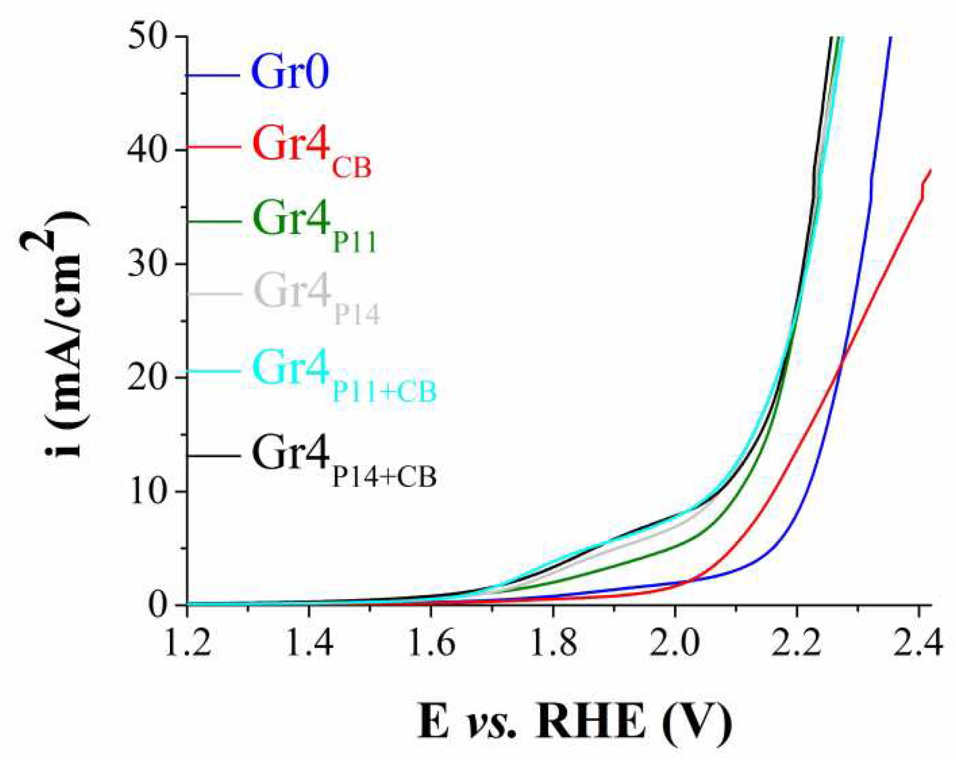
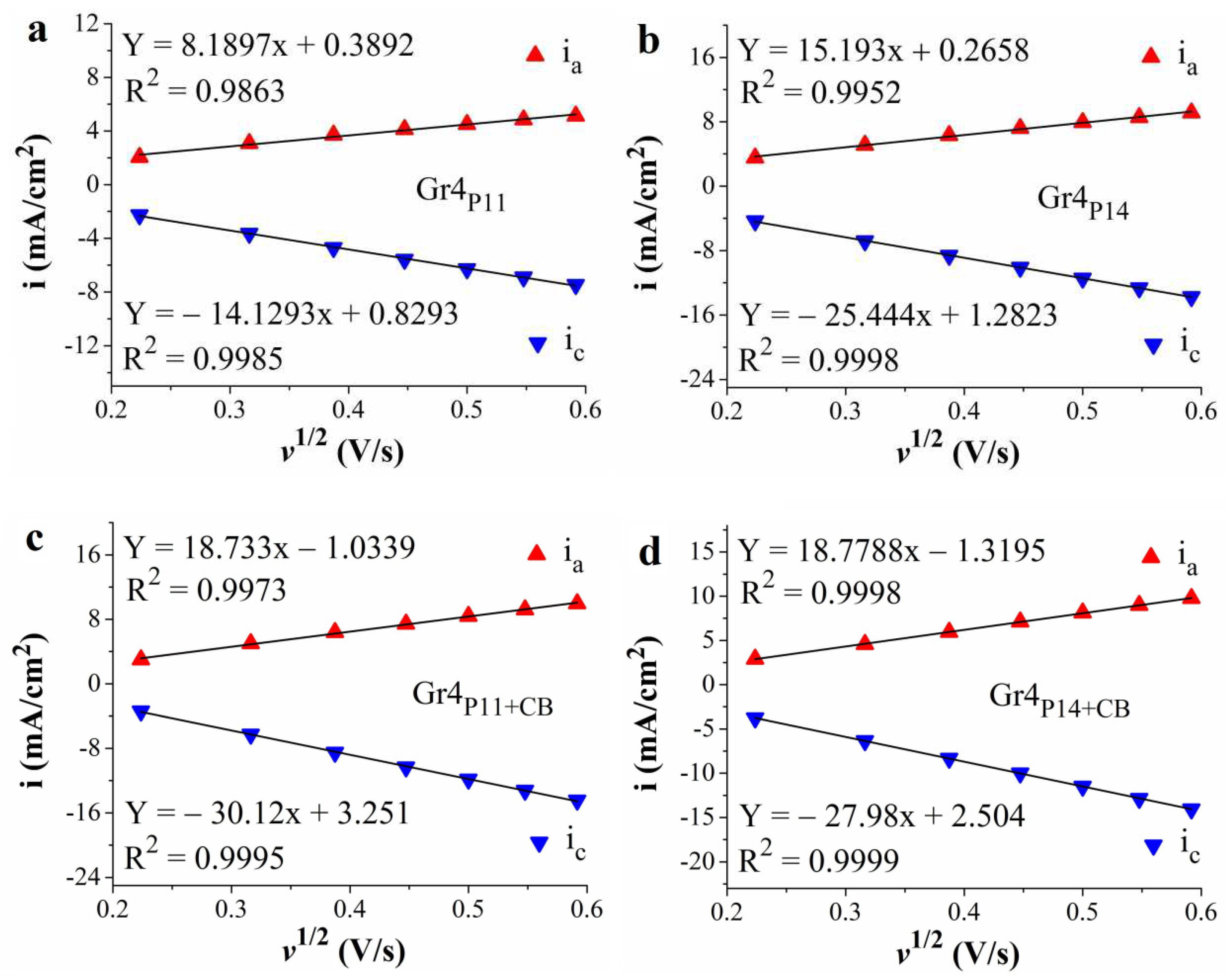
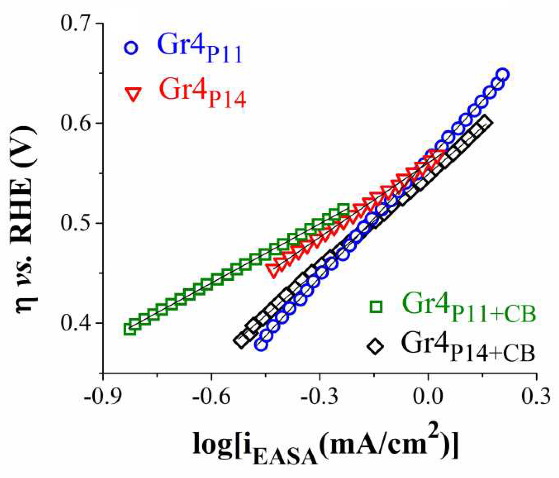
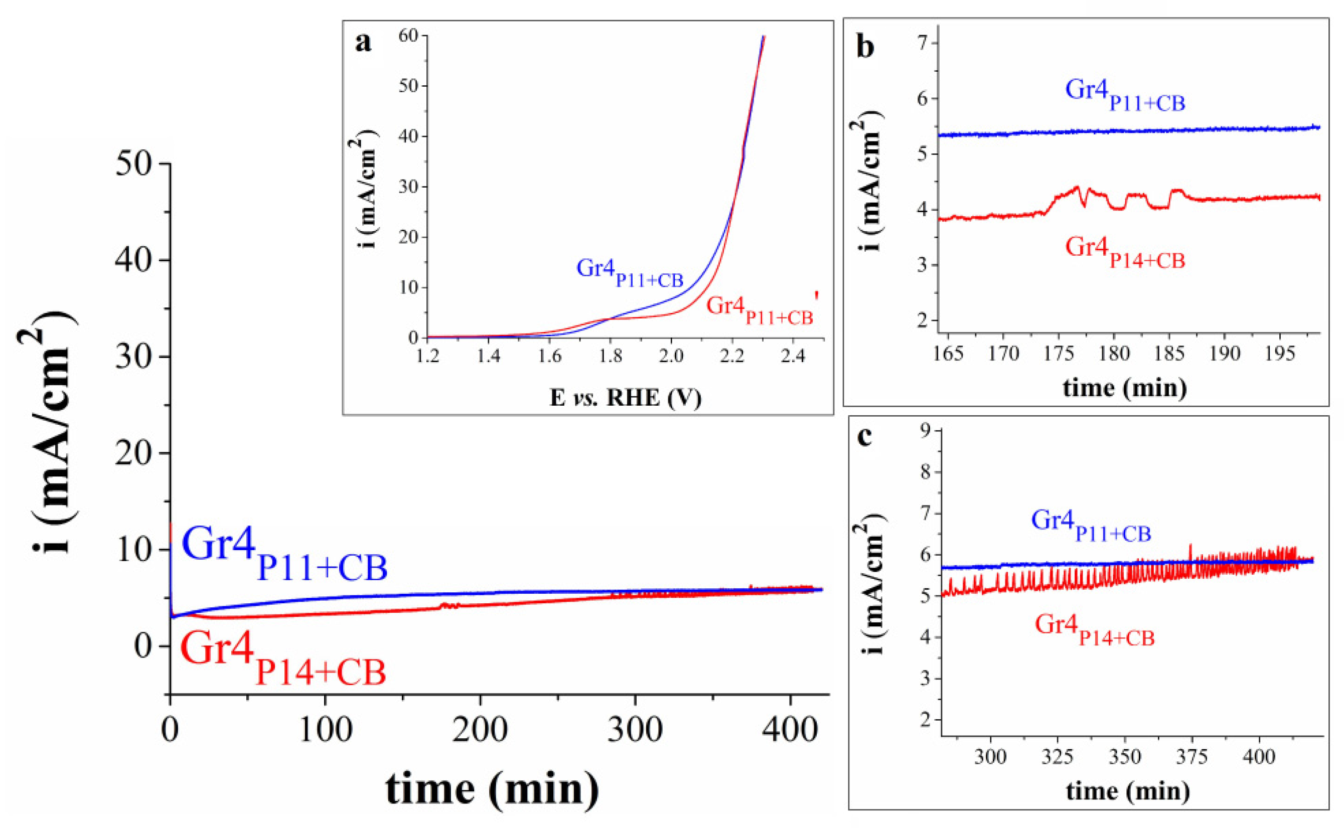
| Electrode | Suspension composition | |||||
|---|---|---|---|---|---|---|
| Procedure 1 | Procedure 3 | P11 (mg) |
P14 (mg) |
Nafion solution (µL) | Carbon Black (mg) | Ethanol (µL) |
| GC1CB | Gr3CB | - | - | 50 | 5 | 450 |
| GC1P11 | Gr3P11 | 5 | - | 50 | - | 450 |
| GC1P11+CB | Gr3P11+CB | 5 | - | 100 | 5 | 900 |
| GC1P14 | Gr3P14 | - | 5 | 50 | - | 450 |
| GC1P14+CB | Gr3P14+CB | - | 5 | 100 | 5 | 900 |
| Electrode | Suspension composition | |||||
|---|---|---|---|---|---|---|
| Procedure 2 | Procedure 4 | P11 (mg) |
P14 (mg) |
Nafion solution (µL) | Carbon Black (mg) | Ethanol (µL) |
| GC2CB | Gr4CB | - | - | 50 | 5 | 150 |
| GC2P11 | Gr4P11 | 5 | - | 50 | - | 150 |
| GC2P11+CB | Gr4P11+CB | 5 | - | 100 | 5 | 300 |
| GC2P14 | Gr4P14 | - | 5 | 50 | - | 150 |
| GC2P14+CB | Gr4P14+CB | - | 5 | 100 | 5 | 300 |
| Electrode | EASA (cm2) | D (cm2/s) |
|---|---|---|
| Gr4P11 | 0.54 | 2.55 x 10⁻⁵ |
| Gr4P14 | 0.74 | 4.85 x 10⁻⁵ |
| Gr4P11+CB | 1.19 | 1.21 x 10⁻⁴ |
| Gr4P14+CB | 0.80 | 5.51 x 10⁻⁵ |
| Electrode | Tafel slope (V/dec) | R2 |
|---|---|---|
| Gr4P11 | 0.392 | 0.9996 |
| Gr4P14 | 0.247 | 0.9993 |
| Gr4P11+CB | 0.197 | 0.9994 |
| Gr4P14+CB | 0.314 | 0.9995 |
Disclaimer/Publisher’s Note: The statements, opinions and data contained in all publications are solely those of the individual author(s) and contributor(s) and not of MDPI and/or the editor(s). MDPI and/or the editor(s) disclaim responsibility for any injury to people or property resulting from any ideas, methods, instructions or products referred to in the content. |
© 2024 by the authors. Licensee MDPI, Basel, Switzerland. This article is an open access article distributed under the terms and conditions of the Creative Commons Attribution (CC BY) license (http://creativecommons.org/licenses/by/4.0/).


