Preprint
Article

Computational Fluid Dynamics Simulation Study on Aerodynamic Characteristics under Unfavorable Conditions during Flight Phase in Ski Jumping

Altmetrics

Downloads

77

Views

25

Comments

0

A peer-reviewed article of this preprint also exists.

This version is not peer-reviewed

Submitted:

11 January 2024

Posted:

12 January 2024

You are already at the latest version

Alerts
Abstract
Objective: The stability of the flight phase in ski jumping is crucial for athletes' performance and safety. This study aims to investigate the influence of unfavorable conditions on aerodynamic characteristics and flight stability through computational fluid dynamics (CFD) numerical simulations. Methods: The ski jumper and the skis are considered as a multi-body system. A detailed three-dimensional (3D) model of this multi-body system under a commonly observed posture during flight is established. The partially averaged Navier-Stokes (PANS) turbulence model is employed, and CFD simulations are conducted to predict the aerodynamic characteristics of the multi-body system under lateral environmental wind and asymmetric postures during flight phase. The conditions of asymmetric postures include yaw rotation and roll rotation. Results: (1) Lateral environmental wind generated yaw force, yaw moment, and roll moment, which influenced the lift, drag, and pitch moment of the athlete. These forces and moments were relatively small at lower wind speeds (less than 3 m/s) and became more significant at higher wind speeds (greater than 4.5 m/s). (2) Under the influence of yaw rotation or roll rotation, the multi-body system exhibited noticeable yaw force, yaw moment, and roll moment, all showing a monotonic increasing trend. Moreover, they had a significant impact on the lift, drag, and pitch moment of the multi-body system. Conclusion: (1) The influence of unfavorable conditions is complex, resulting in significant yaw force, yaw moment, and roll moment on the multi-body system. The adverse effects of roll rotation were generally greater than those of yaw rotation. (2) The multi-body system exhibited self-stabilizing tendencies in yaw and roll. This phenomenon can provide a solution to maintain flight stability by employing appropriate yaw or (and) roll rotation angles, effectively compensating for or even eliminating the adverse effects of lateral environmental wind. (3) Understanding the mechanisms of how unfavorable conditions affect the aerodynamic characteristics and stability during flight in ski jumping can provide valuable assistance for real-time prediction and decision-making during competitions, as well as scientific guidance for training athletes stable flight control and techniques and improving their sport performance.
Keywords: 
Subject: Physical Sciences  -   Biophysics

1. Introduction

Ski jumping performances often consists of four distinct phases: inrun, take-off, flight, and landing, which involve ballistic and aerodynamic aspects. Both aspects impose specific requirements on ski jumpers, such as maximizing lift and minimizing drag. Ballistic factors include the jumper's takeoff position and velocity from the take-off table, while aerodynamic factors encompass the aerodynamic characteristics of the jumper-skis system, including speed, posture, environmental wind, clothing, and skis’ length [1]. After take-off phase, it is crucial for the athlete to assume a stable flying position as soon as possible early during flight phase [2], minimize drag [3], and achieve a complete balance between backward and forward angular momentum rotations [4]. The flight phase is where the aerodynamic characteristics of ski jumping are most evident, and researchers have conducted studies on the aerodynamic characteristics during this phase using wind tunnel experiments, combined field measurements and numerical simulations, among other methods [5,6,7,8,9,10,11,12,13,14,15,16,17,18,19]. Computational Fluid Dynamics (CFD) is the preferred tool for visualizing and analyzing the flow field around the athlete, enabling the analysis of aerodynamic forces, pressure distribution, and detailed flow information during motion. CFD has been widely applied in various sports disciplines, including cycling [20], bobsledding [21], and race walking [22]. CFD is considered an important tool for future research on the aerodynamics of ski jumping [1], although current CFD studies in ski jumping mainly focus on the inrun and flight phases [23,24,25,26,27,28,29,30,31]. Gardan et al. (2017) employed CFD to investigate the effects of the attack angle and velocity on aerodynamic forces, and their numerical results indicated that velocity had little influence on the lift and drag coefficients during the early flight phase, whereas variations in the attack angle had a significant impact on the lift and drag acting on the athlete [9]. Similarly, CFD studies have found that the aerodynamic characteristics of the skis play a more crucial role in the jumper-skis system and should not be overlooked while considering the athlete's posture [29]. Furthermore, environmental wind has a significant influence on the aerodynamic characteristics of ski jumping and the performance of athletes [32,33,34,35,36,37,38]. In addition, Jung et al. (2019) explored the optimization of athlete posture under the influence of wind, where the optimal attack angle of the skis was smaller in headwinds and larger in tailwinds compared to no wind conditions. Under given flight technique constraints, the optimal body-to-skis angle was minimized, except for the final part of the flight, where a smaller angle could be employed to achieve greater jump distance, which is feasible under headwind conditions, albeit with increased difficulty in maintaining flight stability [39].
In summary, previous CFD studies on the aerodynamic characteristics of the flight phase in ski jumping have mainly focused on factors such as flight speed, attack angle, athlete’s posture, skis’ posture, and horizontal headwind or tailwind conditions, all under the assumption of symmetric athlete-skis system postures. However, flight stability is crucial for ensuring the performance and safety of ski jumping [40,41]. In addition to environmental wind, the posture of the multi-body system is highly significant for controlling flight stability and is closely related to the performance of ski jumping. Nevertheless, little is known about the effects of unfavorable conditions such as lateral environmental wind and asymmetric multi-body system postures on the aerodynamic characteristics and stability during the flight phase. To enhance the training of ski jumpers' flight stability techniques and improve their sport performance, as well as provide effective support for real-time prediction and decision-making during competitions, it is essential to conduct numerical simulations of the aerodynamic characteristics during the flight phase of ski jumping under unfavorable conditions such as lateral environmental wind and asymmetric multi-body system postures. By investigating the influence of unfavorable conditions on aerodynamic characteristics and flight stability, this research aims to develop a detailed three-dimensional (3D) model of the athlete-skis system, utilize the partially averaged Navier-Stokes (PANS) turbulence model for CFD simulations, and analyze the forces, moments, and flow field morphology of the multi-body system under different unfavorable conditions, thereby providing insights into the effects of unfavorable conditions on the aerodynamic characteristics and flight stability.

2. Methodology

2.1. Research subject

The research focuses on the multi-body system of ski jumper and skis. Based on the statistical analysis by Müller et al. (2006), the average values of physical characteristics for ski jumpers were selected. These include a height of 177cm, a body mass index (BMI) of 19.5, a ratio of trunk height (sitting height) to height of 0.532, a ski’s length of 258cm, and a ski’s width of 11.5cm [42]. The posture parameters of the multi-body system during flight phase include the attack angle ϕ, the angle α between velocity and skis, the skis opening angle λ, the angle θ between body and skis, the bending angle β of upper body, as shown in Figure 1. In this study, the attack angle ϕ is set to 35°, the angle α between velocity and skis is set to 35°, the angle θ between body and skis is set to 16°, the bending angle β of upper body is set to 18°, the skis opening angle λ is set to 28°, and the velocity V is set to 29m/s.

2.2. Research methodology

2.2.1. Simulation model

This study employs large eddy simulation (LES) technique, which is known for its effectiveness in numerically predicting flow separation around bluff bodies, as validated in previous studies [28,29]. The standard k-ε PANS model has certain limitations in simulating flows with strong vortices and large curvature bent wall flows. However, the Renormalization Group (RNG) k-ε PANS model has shown improvements in predicting such flows [43]. To obtain more accurate results, the RNG k-ε PANS turbulence model is adopted in this study, and its governing equations are expressed as follows:
( ρ k u ) t + ( ρ U j k u ) x j = x j [ α k ( μ + μ u σ u ) k u x j ] + P k u ρ ε u
( ρ ε u ) t + ( ρ U j ε u ) x j = x j [ α k ( μ + μ u σ u ) ε u x j ] + C ε 1 P k u ε u k u C ε 2 * ρ ε u 2 k u
In the equations, Uj represents the resolved velocity field, t denotes time, ρ represents fluid density, μ denotes the dynamic viscosity coefficient, μu represents the turbulent viscosity coefficient, fk represents the unresolved turbulent kinetic energy ratio, fε represents the unresolved turbulent kinetic energy dissipation rate ratio, ku represents the unresolved local time-averaged turbulent kinetic energy, and εu represents the unresolved local time-averaged turbulent kinetic energy dissipation rate.
Where:
f k = k u k
f ε = ε u ε
μ u = ρ C μ k u 2 ε u
σ u = f k 2 f ε
C ε 2 * = C ε 1 + f k f ε ( C ε 2 C ε 1 )
η = ( 2 S i j S i j ) 1 / 2 k u ε u f ε f k
S i j = 1 2 ( U i x j + U j x i )
C ε 1 = C ε 1 η ( 1 η / η 0 ) 1 + δ η 3
The values of the constants in the model are: C μ = 0.0845 , α k = α ε = 1.39 , C ε 1 = 1.42 , C ε 2 = 1.68 , η 0 = 4.377 , δ = 0.012 .
The governing equations are discretized using the finite volume method. The coupling of pressure and velocity is solved using a consistent and coordinated approach based on the semi-implicit algorithm for pressure-linked equations (SIMPLEC). The time discretization is performed using a second-order difference scheme. The turbulent kinetic energy and velocity terms are discretized using a second-order upwind scheme. The time step size is set to 0.0001s.

2.2.2. Validation of Model Independence from the Grid

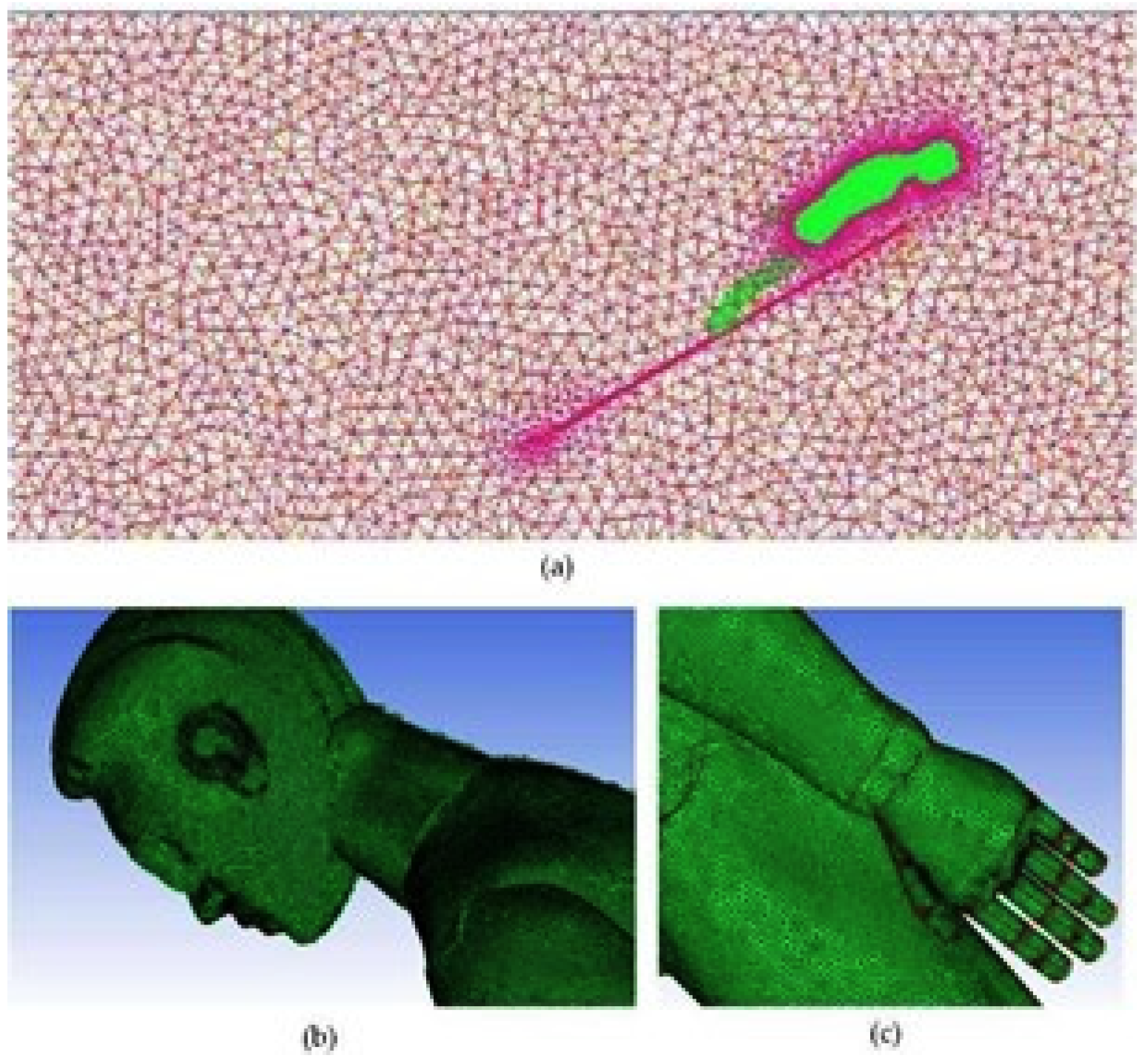
Based on the structural characteristics of the research object and the selected flight parameters, a 3D solid model of the multi-body system is created. The athlete's body features are meticulously modeled, including the fingers, ears, face, shoulders, and hips, which can be clearly distinguished.
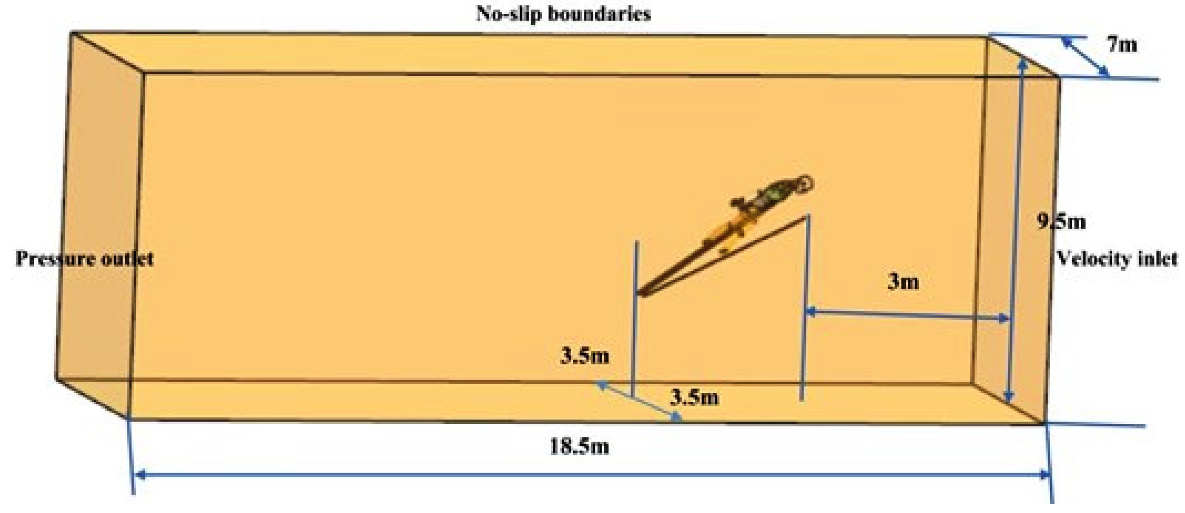
The computational domain size for the multi-body system is 18.5m in length, 7m in width, and 9.5m in height, as shown in Figure 2. Considering the flow separation in the wake and the potential influence of the athletes' body shape on the flow field, the multi-body system's refined 3D solid model is divided into several regions for grid generation. These regions include the athlete's body surface area, the skis’ surface area, the wake region behind the athlete's upper arms, the wake region behind the waist-hip junction, the wake region behind other parts of the athlete's body, the wake region behind the skis, and the region far away from the athlete and the skis.
To meet the computational requirements of the PANS model, an appropriate grid refinement strategy is employed around the athlete's body. The grid partitioning strategy used in this study has been validated in previous research [28,29]. Specifically, for the aforementioned grid model, four grid densities are selected for each subregion, and varying degrees of uniform refinement are applied within each subregion. The number of grid points ranges from 10 million to 28.38 million, and grid independence verification is conducted. The results of the verification, as shown in Table 1, indicate that the lift-to-drag ratio obtained from the four grid validation calculations is approximately 1.95. This demonstrates that even with a computational domain discretization scheme using 10 million grid nodes, accurate prediction of the aerodynamic characteristics of the multi-body system can be achieved.

2.2.3. Boundary Conditions and Computational Conditions

The boundary conditions are set as follows: 1) Inlet: Velocity inlet with the inlet velocity determined based on the flight speed. 2) Outlet: Pressure outlet with a pressure of 101325 Pa (atmospheric pressure). 3) Middle cross-section: Periodic boundary condition. 4) Other walls: No-slip boundary condition. 5) Gas: Incompressible air. 6) Environment: Constant gravitational acceleration g0 = 9.807 m/s².
In this study, unfavorable conditions include lateral wind conditions and posture asymmetry conditions. The posture asymmetry conditions include yaw rotation and roll rotation, as shown in Table 2. For each adverse condition, CFD numerical simulations are performed to extract the forces and moments acting on the multi-body system and visually display the flow field information around the system. In these simulations, the lateral wind blows in the +Z direction, and both yaw rotation and roll rotation occur clockwise around their respective rotation axes. Yaw rotation refers to the system's rotation around a straight line parallel to the Y-axis and passing through the center of mass (CM). The yaw rotation angle represents the rotation angle of the system around the yaw rotation axis. Roll rotation refers to the system's rotation around a straight line parallel to the X-axis and passing through the CM. The roll rotation angle represents the rotation angle of the system around the roll rotation axis, as shown in Figure 1.

3. Results

3.1. Aerodynamic Forces and Moments

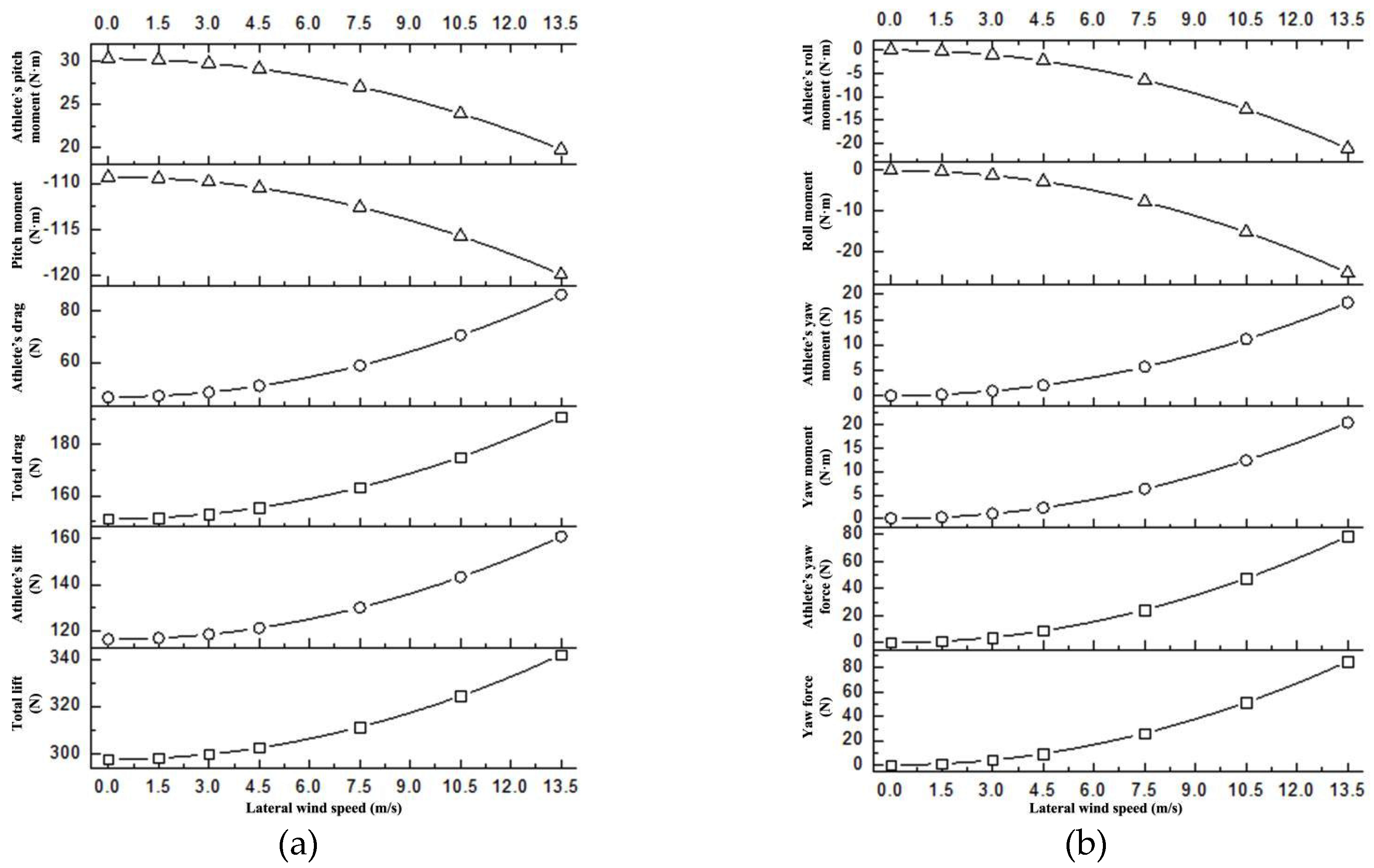
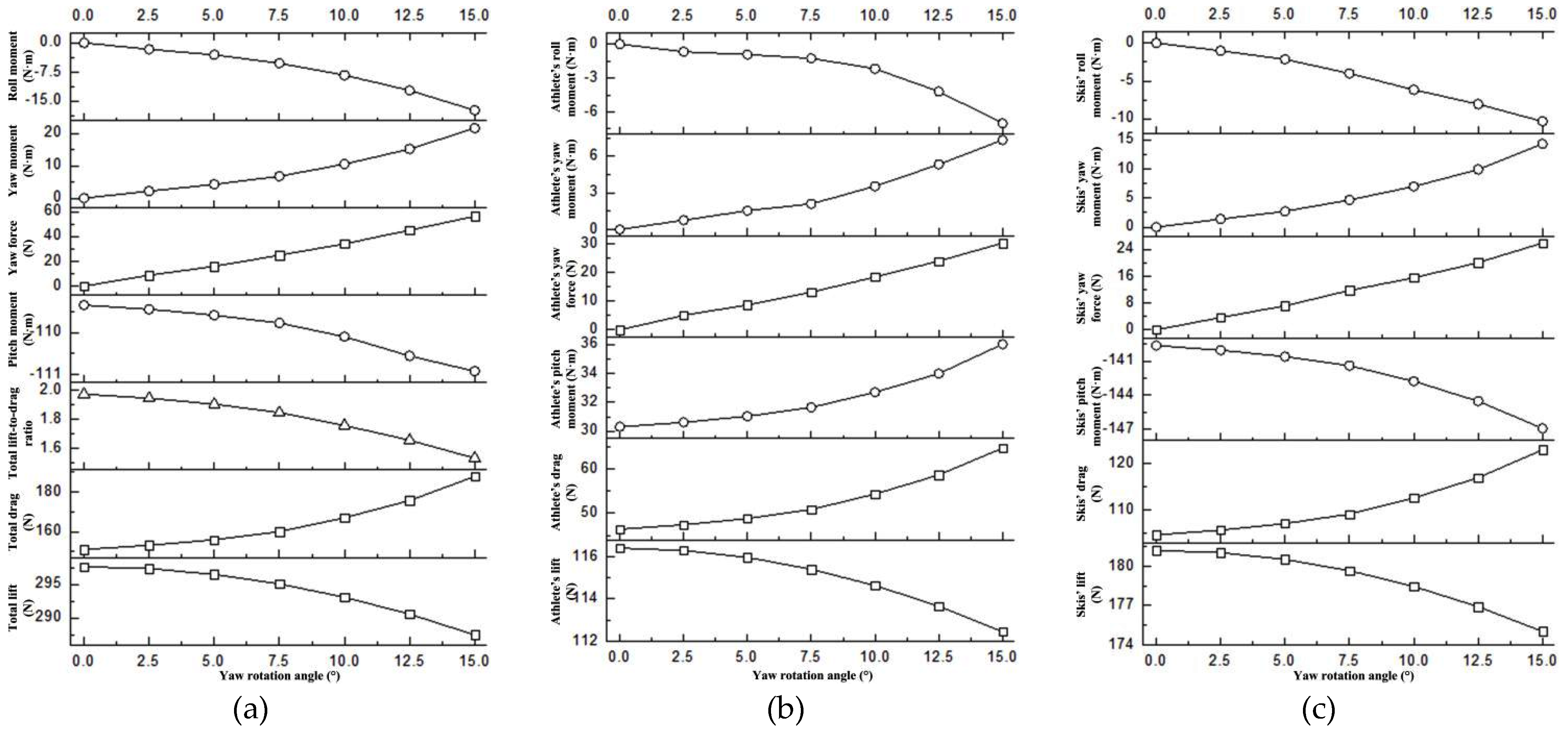
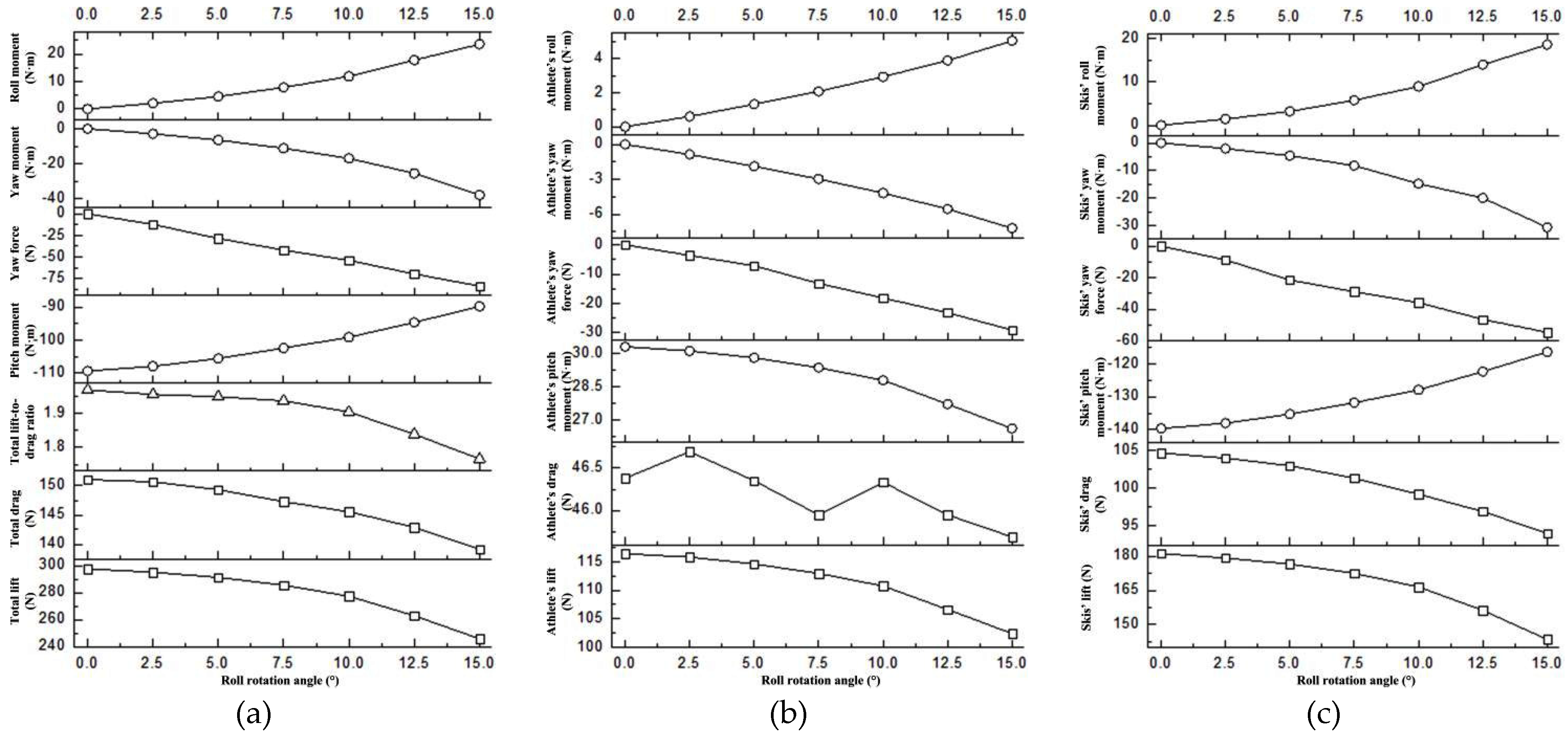
The aerodynamic forces acting on the multi-body system include lift and drag. It is important to note that the majority of these forces do not act at the system's CM, which may result in corresponding moments. Under lateral wind and asymmetric postures, there is a possibility of generating yaw force, which can lead to the generation of corresponding moments. Table 3, Table 4 and Table 5 present the mechanical characteristics under different unfavorable conditions. Figure 4, Figure 5 and Figure 6 display the variation curves of the mechanical characteristics with respect to the unfavorable conditions. In the results, all forces are the resultant forces acting on the multi-body system or individually on the athlete or the skis, of the same nature. The moments, on the other hand, refer to the moments relative to the system’s CM. The pitch moment has a rotation axis along the Z-axis, the roll moment along the X-axis, and the yaw moment along the Y-axis, with the positive and negative directions of these moments following the right hand rule. The lift-to-drag ratio is calculated as the ratio of lift to drag.
The mechanical characteristics of the multi-body system under different lateral wind speeds are depicted in Figure 4. It can be observed that, influenced by the lateral wind, the multi-body system exhibits significant yaw force, yaw moment, and roll moment. The magnitudes of these forces and moments increase in a parabolic curve fashion as the wind speed increases. At a wind speed of 1.5 m/s, the values of the yaw force, yaw moment, and roll moment are negligible. However, when the wind speed reaches 7.5 m/s, the yaw force is approximately 26.3 N, the yaw moment is approximately 6.32 N·m, and the roll moment is approximately 7.8 N·m. Additionally, the lateral wind also affects the lift, drag, and pitch moment of the multi-body system and the athlete. Similar to the forces, the magnitudes of these forces and moments increase in a parabolic curve fashion as the wind speed increases. At a wind speed of 1.5 m/s, the changes in lift, drag, and pitch moment can be considered negligible. However, when the wind speed reaches 7.5 m/s, the total lift increases by approximately 13.7 N, the total drag increases by approximately 12.3 N, and the pitch moment increases by approximately 3.25 N·m.
The variation curves of the mechanical characteristics of the multi-body system under different yaw rotation angles are shown in Figure 5. It can be observed that, influenced by the yaw rotation, the multi-body system exhibits asymmetric flight postures, resulting in significant yaw force, yaw moment, and roll moment. The yaw force acts along the positive Z-axis, the yaw moment along the positive Y-axis, and the roll moment along the negative X-axis. The magnitudes of these forces and moments increase monotonically with the yaw rotation angle. Moreover, although the yaw force of the athlete is greater than that of the skis, the magnitudes of the athlete's yaw moment and roll moment are smaller than those of the skis. At a yaw rotation angle of 2.5°, the yaw force, yaw moment, and roll moment of the multi-body system are relatively small, approximately 8.78 N, 2.16 N·m, and -1.67 N·m, respectively. However, when the yaw rotation angle increases to 7.5°, the yaw force is 24.89 N, the yaw moment is 6.78 N·m, and the roll moment is -5.26 N·m. Additionally, the yaw rotation also has a significant impact on the lift, drag, and pitch moment of the multi-body system. The lift of the multi-body system, athlete, and skis decreases monotonically with the yaw rotation angle, while the drag of the multi-body system and ski increases monotonically with the yaw rotation angle. Consequently, the total lift-to-drag ratio of the multi-body system exhibits a monotonically decreasing trend. Furthermore, although the variation of the pitch moment of the multi-body system is relatively insignificant, the pitch moments of the athlete and skis exhibit noticeable changes, with their magnitudes increasing monotonically with the yaw rotation angle. At a yaw rotation angle of 15°, the reduction in total lift of the multi-body system is 10.14 N, the increase in total drag is 36.71 N, the decrease in the total lift-to-drag ratio is 0.439, and the increase in pitch moment is 2.59 N·m.
The mechanical characteristics of the multi-body system under different roll rotation angles are shown in Figure 6. It can be observed that the asymmetry of the flight posture of the multi-body system is significantly influenced by the roll rotation, resulting in noticeable yaw force, yaw moment, and roll moment. Specifically, the yaw force is directed along the negative Z-axis, the yaw moment along the negative Y-axis, and the roll moment along the positive X-axis. The magnitudes of these forces and moments consistently increase with the increasing roll rotation angles, displaying a monotonic upward trend. Furthermore, it is evident that the magnitudes of yaw force, yaw moment, and roll moment exerted on the athlete are all significantly smaller than those exerted on the skis. For instance, when the roll rotation angle is 2.5°, the magnitudes of yaw force, yaw moment, and roll moment experienced by the multi-body system are relatively smaller, measuring -12.33N, -3.63N·m, and 2.04N·m, respectively. However, when the roll rotation angle increases to 5°, the yaw force reaches -28.72N, the yaw moment reaches -6.47 N·m, and the roll moment reaches 4.53N·m. Moreover, the roll rotation also has a significant impact on the lift, drag, and pitch moment of the multi-body system. Apart from the athlete's drag, which remains relatively constant, the lift exerted on the multi-body system, athlete, and skis, as well as the drag experienced by the multi-body system and skis, all exhibit a monotonic decrease with increasing roll rotation angles. Consequently, the total lift-to-drag ratio of the multi-body system demonstrates a monotonic decrease (with a slight reduction before reaching a roll rotation angle of 7.5°, followed by a substantial decrease). Additionally, the magnitudes of the pitch moment for the multi-body system, athlete, and skis all decrease monotonically with increasing roll rotation angles. When the roll rotation angle reaches 15°, the reduction in total lift is 51.82N, the reduction in total drag is 11.89N, the reduction in the total lift-to-drag ratio is 0.204, and the reduction in the pitch moment magnitude is 19.51N·m.

3.2. Flow field morphology

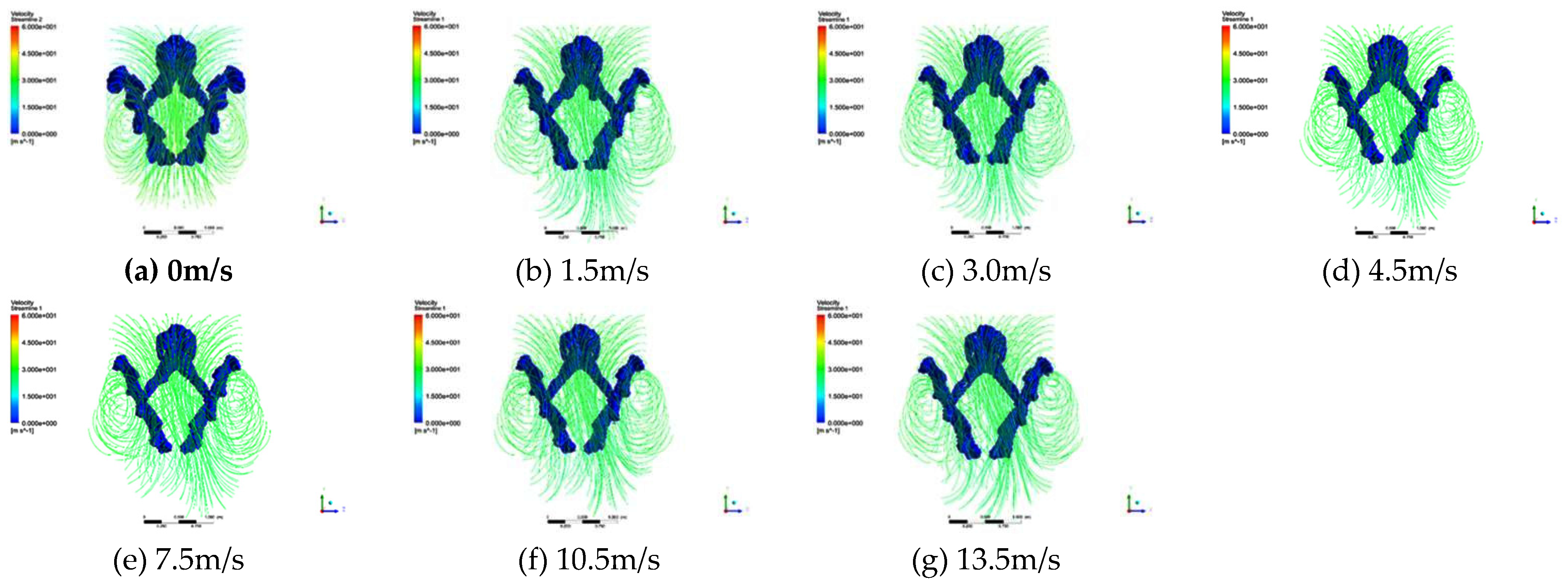
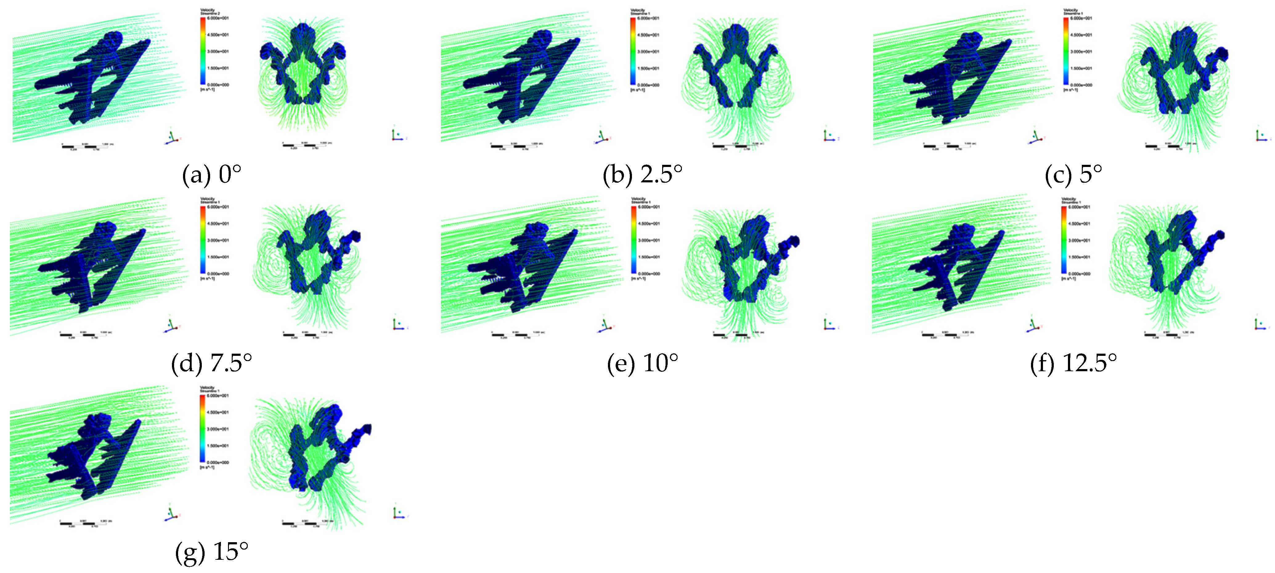
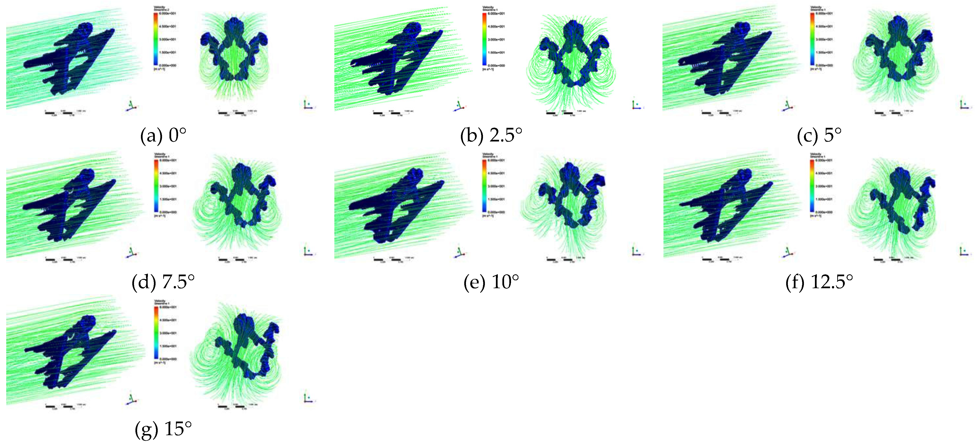
The distribution of vortices and the streamline of airflow velocities under unfavorable conditions are shown in Figure 7, Figure 8 and Figure 9. Vortex structures predominantly appear behind the athlete and the skis, contributing to accelerated energy dissipation. Additionally, there is flow separation occurring on both the athlete and the skis’ surfaces. For the athlete, two pairs of vortex structures are primarily formed behind them, while for the skis, six pairs of vortex structures are mainly generated at its rear. As depicted in Figure 7, with an increase in the lateral wind speed, the scale of vortex structures behind the skis changes relatively insignificantly. However, the vortex patterns behind the athlete exhibit significant variations, shifting increasingly towards the direction of the lateral wind. Figure 8 shows that with a change in the yaw rotation angle, there is no apparent variation in the velocity values of the streamlines, but there is a noticeable overall rightward shift of the streamlines. Simultaneously, the vortex patterns undergo significant changes, transitioning from an initial symmetrical form to an asymmetrical form, with recurring variations in vortex size. The vortex size on the left side of the skis gradually increases. Furthermore, Figure 9 reveals that with a change in the roll rotation angle, there is no apparent variation in the velocity values of the streamlines, but there is an increasingly evident overall leftward shift of the streamlines. The vortex patterns also undergo significant changes, transitioning from an initial symmetrical form to an asymmetrical form. However, the size of the vortices behind the athlete and the skis gradually decreases.

4. Discussion

4.1. The universality of the research findings

Müller et al. (1996) and Schmolzer et al. (2005) statistically analyzed the actual measurement results of world-class ski jumpers’ posture parameters during the flight stage, and provided the typical ranges of various posture parameters, including the attack angle ϕ (ranging from 25° to 40°), the angle between velocity and skis α (ranging from 25° to 40°), the angle between body and skis θ (ranging from 10° to 20°), the bending angle of upper body β (ranging from 10° to 25°), the skis opening angle λ (ranging from 20° to 40°), and the velocity V (ranging from 25 m/s to 32 m/s) [15,32]. Furthermore, Hu et al. (2021; 2018) conducted CFD studies and recommended the optimal ranges for the skis opening angle λ (ranging from 24° to 32°), the bending angle of upper body β (ranging from 14° to 18°), and the angle between body and skis θ (ranging from 16° to 20°). [28,29] In this study, the values of the posture parameters, including the attack angle ϕ, the angle between velocity and skis α, the angle between body and skis θ, the bending angle of upper body β, the skis opening angle λ, and the velocity V, all fall within the aforementioned ranges, indicating the good universality of the research findings.

4.2. The influence of lateral environmental wind

Firstly, it is evident that at lower wind speeds (less than 3 m/s), the yaw force, yaw moment, and roll moment increase slowly. However, at higher wind speeds (greater than 4.5 m/s), these forces and moments experience a rapid increase, which is highly detrimental to the flight stability and control. Data analysis reveals an approximate linear relationship between the yaw force, yaw moment, roll moment, and the square of the wind speed. It should be noted that the athlete-generated yaw force, yaw moment, and roll moment play a dominant role, while the influence of the skis is relatively small. Therefore, it is crucial to focus on the impact of the athlete's posture under lateral wind conditions on the aerodynamic characteristics and stability during flight phase.
Secondly, at lower wind speeds (less than 3 m/s), the lift, drag, and pitch moment increase gradually. However, at higher wind speeds (greater than 4.5 m/s), the lift, drag, and pitch moment start to increase rapidly, imposing higher demands on the athlete's flight control. An interesting observation is that the increase in total lift, total drag, and pitch moment is almost identical to the increase in the athlete's lift, drag, and pitch moment. This suggests that, due to the similarity between the athlete's body shape and an aircraft wing, the lateral wind not only generates drag effects (as mentioned above in the yaw force) but also produces lift effects. Consequently, the athlete's lift, drag, and pitch moment change, leading to variations in the total lift, total drag, and pitch moment of the multi-body system. However, the mechanical characteristics of the skis show minimal changes.
Furthermore, from the flow field results depicted in Figure 7, it is observed that as the lateral wind speed increases, the scale of vortex structures behind the skis undergoes relatively minor changes. However, the vortex patterns behind the athlete exhibit significant variations, shifting increasingly towards the direction of the lateral wind. This indicates that the athlete is more affected by the lateral wind, resulting in more pronounced changes in forces and moments generated by the athlete. This observation aligns with the previously obtained numerical statistics of the mechanical characteristics.

4.3. The influence of yaw rotation

It is observed that as the multi-body system undergoes yaw rotation, its initial symmetric configuration gradually transforms into an asymmetric shape, altering its flow configurations. The results of this study demonstrate that yaw rotation significantly generates yaw force, yaw moment, and roll moment, while also exerting a significant influence on the lift, drag, lift-to-drag ratio, and pitch moment of the multi-body system. From Table 4 and Figure 5, it is evident that yaw rotation leads to a notable decrease in the total lift-to-drag ratio and complicates the force distribution on the multi-body system, thereby exerting unfavorable effects on the mechanical characteristics and impeding stable flight and athlete’s sport performance. It should be noted that the numerical values of aerodynamics characteristics in these influence relationships may vary depending on the flight postures of the multi-body system.
Notably, the multi-body system in this study exhibits clockwise yaw rotation in the top view, rotating along the -Y axis, but consequently generates yaw moments in the +Y direction. According to the principles of rotational motion, the yaw moment induces an angular acceleration opposite to the yaw rotation direction of the multi-body system, thus causing the system to return to its initial symmetric configuration and exhibiting a suppressing effect on the yaw rotation. This phenomenon can be referred to as yaw self-stabilization or static equilibrium, which has been observed in previous studies conducted by Marqués-Bruna et al. (2009) in the context of two-dimensional numerical calculation of aerodynamics stability on the yaw direction in ski jumping [41].
It is worth noting that when the yaw rotation angle is 2.5°, the yaw force, yaw moment, and roll moment of the multi-body system are relatively small, measuring 8.78 N, 2.16 N·m, and -1.67 N·m, respectively. However, when the yaw rotation angle increases to 7.5°, the yaw force reaches 24.89 N, the yaw moment becomes 6.78 N·m, and the roll moment reaches -5.26 N·m. Similarly, under lateral wind conditions, the multi-body system exhibits significant yaw force, yaw moment, and roll moment. For instance, when the wind speed in the +Z direction is 4.5 m/s, the yaw force, yaw moment, and roll moment of the multi-body system are 9.48 N, 2.27 N·m, and -2.80 N·m, respectively. When the wind speed in the +Z direction increases to 7.5 m/s, the yaw force, yaw moment, and roll moment become 26.31 N, 6.32 N·m, and -7.80 N·m, respectively. It can be observed that the results of the yaw force, yaw moment, and roll moment are similar for the two scenarios: a yaw rotation angle of 2.5° and a lateral wind speed of 4.5 m/s, as well as a yaw rotation angle of 7.5° and a lateral wind speed of 7.5 m/s. This finding suggests that employing an appropriate yaw rotation angle may potentially counteract or even eliminate the adverse effects of lateral wind on the flight stability of ski jumping.
Furthermore, the flow field results in Figure 8 demonstrate that with variations in the yaw rotation angle, the velocity values of the streamlines exhibit minimal changes, but the streamlines shift noticeably towards the right rear. Concurrently, the vortex patterns undergo significant transformations, transitioning from an initial symmetric configuration to an asymmetric one, with repeated fluctuations in vortex structure size. Specifically, the vortex structure size of the left ski gradually increases. These observations indicate that yaw rotation significantly alters the original mechanical characteristics of the multi-body system, giving rise to new lateral forces and corresponding moments that align with the previously obtained numerical statistics of the mechanical characteristics.

4.4. The influence of roll rotation

As the multi-body system undergoes roll rotation, its initial symmetric configuration gradually transforms into an asymmetric shape, altering its flow configurations. The findings of this study indicate that roll rotation significantly generates yaw force, yaw moment, and roll moment, while also exerting a substantial influence on the lift, drag, lift-to-drag ratio, and pitch moment of the system. Table 5 and Figure 6 clearly demonstrate that roll rotation leads to a significant decrease in the total lift-to-drag ratio and complicates the force distribution on the system. These effects have unfavorable implications for the mechanical characteristics, hindering stable flight and athlete’s sport performance. It should be noted that the numerical values of aerodynamics characteristics in these influence relationships may vary depending on the flight postures of the multi-body system.
It is noteworthy that the multi-body system in this study undergoes clockwise roll rotation in the top view, rotating along the -X axis, resulting in roll moments in the +X direction. According to the principles of rotational motion, the roll moment induces an angular acceleration opposite to the roll rotation direction, causing the system to return to its initial symmetric configuration and exhibiting a suppressing effect on roll rotation. This phenomenon is referred to as roll self-stabilization or static equilibrium, which has also been observed in previous studies conducted by Marqués-Bruna et al. (2009) regarding two-dimensional numerical calculation of aerodynamics stability on the roll direction in ski jumping [41].
It is worth noting that when the roll rotation angle is 2.5°, the yaw force, yaw moment, and roll moment of the system are relatively small, measuring -12.33 N, -2.91 N·m, and 2.04 N·m, respectively. However, when the roll rotation angle increases to 5°, the yaw force becomes -28.72 N, the yaw moment is -6.47 N·m, and the roll moment reaches 4.53 N·m. Similarly, under lateral wind conditions, the system exhibits significant yaw force, yaw moment, and roll moment. For example, when the wind speed in the +Z direction is 4.5 m/s, the yaw force, yaw moment, and roll moment of the system are 9.48 N, 2.27 N·m, and -2.80 N·m, respectively. When the wind speed in the +Z direction increases to 7.5 m/s, the yaw force, yaw moment, and roll moment become 26.31 N, 6.32 N·m, and -7.80 N·m, respectively. It can be observed that the results of the yaw force, yaw moment, and roll moment are similar for the two scenarios: a roll rotation angle of 2.5° and a lateral wind speed of 4.5 m/s, as well as a roll rotation angle of 5° and a lateral wind speed of 7.5 m/s. This finding suggests that employing an appropriate roll rotation angle may potentially counteract or even eliminate the adverse effects of lateral wind on the flight stability of ski jumping.
Furthermore, the flow field results in Figure 9 demonstrate that with variations in the roll rotation angle, the velocity values of the streamlines exhibit minimal changes, but the streamlines noticeably shift towards the left rear. Simultaneously, the vortex patterns undergo significant transformations, transitioning from an initial symmetric configuration to an asymmetric one, with a gradual decrease in vortex structure size behind the athlete and skis. These observations indicate that roll rotation significantly alters the original mechanical characteristics of the system, giving rise to new lateral forces and corresponding moments that align with the previously obtained numerical statistics of the mechanical characteristics.

5. Conclusion

1)
Lateral environmental wind generates yaw force, yaw moment, and roll moment. These forces and moments are minimal at lower wind speeds (less than 3 m/s) but become more noticeable and cannot be ignored at higher wind speeds (greater than 4.5 m/s). However, the yaw force, yaw moment, and roll moment generated by the athlete are dominant, while the influence of the skis is minimal. Additionally, lateral wind affects the lift, drag, and pitch moment of the athlete. The impact is minimal at lower wind speeds but becomes more evident and cannot be neglected at higher wind speeds, although it has almost no effect on the skis.
2)
Under the conditions of asymmetric postures, the multi-body system experiences noticeable yaw force, yaw moment, and roll moment, while also significantly affecting the lift, drag, lift-to-drag ratio, and pitch moment of the system. Among these effects, the adverse impact of roll rotation is generally more significant than that of yaw rotation, given the same rotation angle.
3)
The multi-body system exhibits yaw self-stabilization and roll self-stabilization phenomena, which can provide a solution for maintaining flight stability. This can be achieved by adopting an appropriate yaw rotation angle and/or roll rotation angle to partially or even completely counteract the adverse effects of lateral environmental wind.
4)
This study, utilizing CFD numerical simulations, presents the first investigation into the mechanisms underlying the effects of unfavorable conditions on aerodynamic characteristics and stability of flight phase in ski jumping. It provides important scientific guidance for training athletes in achieving stable flight and enhancing their sport performance. Furthermore, it facilitates the formulation of effective technical requirements to improve flight stability and offers valuable support for real-time prediction and decision-making during competitions.

Author Contributions

Formal analysis, Qi HU; Methodology, Qi HU and Weidi TANG; Writing - original draft, Qi HU and Weidi TANG; Writing - review & editing, Qi HU, Weidi TANG and Yu LIU; Funding acquisition, Qi HU and Yu LIU.

Funding

This research was funded by the National Natural Science Foundation of China, grant number 11802068 and 11932013, and the National key research and development plan project of China, grant number 2018YFF0300500.

Institutional Review Board Statement

Not applicable.

Informed Consent Statement

Not applicable.

Conflicts of Interest

The authors declare no conflict of interest.

References

  1. Hu, Q.; Chen, Q.; Zhang, W. A review of aerodynamics research in ski jumping. China Sport Sci. Tech. 2018, 54, 132–139. [Google Scholar]
  2. Virmavirta, M.; Isolehto, J.; Komi, P.; Brüggemann, G.P.; Müller, E.; Schwamederet, H. Characteristics of the early flight phase in the Olympic ski jumping competition. J. Biomech. 2005, 38, 2157–2163. [Google Scholar] [CrossRef] [PubMed]
  3. Murakami, M.; Iwase, M.; Seo, K.; Ohgi, Y.; Koyanagi, R. Ski jumping flight skill analysis based on high-speed video image[J]. Procedia Eng. 2010, 2, 2381–2386. [Google Scholar] [CrossRef]
  4. Schwameder, H. Biomechanics research in ski jumping: 1991-2006. Sports Biomech. 2008, 7, 114–136. [Google Scholar] [CrossRef]
  5. Hu, Q.; Liu, Y. A review of wind tunnel experimental research on aerodynamic drag reduction in winter sports. China Sport Sci. Tech. 2022, 42, 55–67. [Google Scholar]
  6. Virmavirta, M.; Kivekäs, J. Aerodynamics of an isolated ski jumping ski. Sports Eng. 2019, 22, 1–6. [Google Scholar] [CrossRef]
  7. Elfmark, O.; Ettema, G.; Gilgien, M. Assessment of the steady glide phase in ski jumping. J. Biomech. 2022, 139, 111139. [Google Scholar] [CrossRef]
  8. Virmavirta, M.; Kivekäs, J. Is it still important to be light in ski jumping? Sports Biomech. 2021, 20, 407–418. [Google Scholar] [CrossRef]
  9. Gardan, N.; Schneider, A.; Polidori, G.; Trenchard, H.; Seigneur, J.M.; Beaumont, F.; Fourchet, F.; Taiar, R. Numerical investigation of the early flight phase in ski-jumping. J. Biomech. 2017, 50, 29–34. [Google Scholar] [CrossRef]
  10. Jung, A.; Staat, M.; Müller, W. Flight style optimization in ski jumping on normal, large, and ski flying hills. J. Biomech. 2014, 47, 716–722. [Google Scholar] [CrossRef] [PubMed]
  11. Lee, K.D.; Park, M.J.; Kim, K.Y. Optimization of ski jumper’s posture considering lift-to-drag ratio and stability. J. Biomech. 2012, 45, 2125–2132. [Google Scholar] [CrossRef]
  12. Yu, J.; Ma, X.; Qi, S.; Liang, Z.; Wei, Z.; Li, Q.; Ni, W.; Wei, S.; Zhang, S. Key transition technology of ski jumping based on inertial motion unit, kinematics and dynamics. Biomed. Eng. Online. 2023, 22, 21. [Google Scholar] [CrossRef]
  13. Grosz, W.R. Improving performance by adopting the optimal flight position in ski jumping. Bulletin of the Transilvania University of Brasov, Series IX: Sciences of Human Kinetics. 2020, 13, 139–144. [Google Scholar] [CrossRef]
  14. Schmolzer, B.; Müller, W. The importance of being light: aerodynamic forces and weight in ski jumping. J. Biomech. 2002, 36, 1059–1069. [Google Scholar] [CrossRef] [PubMed]
  15. Schmolzer, B.; Müller, W. Individual flight styles in ski jumping: results obtained during Olympic games competitions. J. Biomech. 2005, 38, 1055–1065. [Google Scholar] [CrossRef] [PubMed]
  16. Murakami, M.; Iwase, M.; Seo, K.; Ohgi, Y.; Koyanagi, R. High-speed video image analysis of ski jumping flight posture. Sports Eng. 2014, 17, 217–225. [Google Scholar] [CrossRef]
  17. Seo, K.; Watanabe, I.; Murakami, M. Aerodynamic force data for a V-style ski jumping flight. Sports Eng. 2004, 7, 31–39. [Google Scholar] [CrossRef]
  18. Müller, W. Performance factors in ski jumping. J. Biomech. 2006, 39, 192–213. [Google Scholar] [CrossRef]
  19. Ryu, M.; Cho, L.; Cho, J. Aerodynamic analysis on postures of ski jumpers during flight using computational fluid dynamics. T. Jpn. Soc. Aeronaut. S. 2015, 58, 204–212. [Google Scholar] [CrossRef]
  20. Mannion, P.; Toparlar, Y.; Blocken, B.; Hajdukiewicz, M.; Andrianne, T.; Cliffordet, E. Improving CFD prediction of drag on Paralympic tandem athletes: influence of grid resolution and turbulence model. Sports Eng. 2018, 21, 123–135. [Google Scholar] [CrossRef]
  21. Hu, Q.; Wang, X.; Liu, Y. Research progress of bobsleigh aerodynamics. J. Med. Biomech. 2020, 35, 377–383. [Google Scholar]
  22. Zhang, Y.; Ke, P.; Hong, P. Aerodynamic drag reduction analysis of race walking formations based on CFD numerical simulations and wind tunnel experiments. Appl. Sci. 2023, 13, 10604. [Google Scholar] [CrossRef]
  23. Tang, W.; Suo, X.; Yang, C.; Cao, F.; Wu, X.; Liu, Y. Computational fluid dynamics simulation and optimization of in-run stage in ski-jumping. China Sport Sci. 2022, 42, 62–70. [Google Scholar]
  24. Yu, J.; Liao, Z.; Ma, X.; Qi, S.; Liang, Z.; Wei, Z.; Zhang, S. Optimization of stable flight posture of ski jumping based on computational fluid dynamics simulation technology. Sports Biomech. 2023. [Google Scholar] [CrossRef]
  25. Li, X.; Wang, X.; Chen, L.; Zhao, T. Effects of body angles on the aerodynamic characteristics in the flight period of ski jumping: a simulation study. Sports Biomech. 2023. [Google Scholar] [CrossRef]
  26. Cao, L.; Guo, Y.; Li, X.; Chen, L.; Wang, X.; Zhao, T. Optimization of ski attitude for the in-flight aerodynamic performance of ski jumping. Biology. 2022, 11, 1362–1373. [Google Scholar] [CrossRef] [PubMed]
  27. Zhang, L.; Li, X.; Wang, X.; Chen, L.; Zhao, T. Performance and biomechanics in the flight period of ski jumping: Influence of ski attitude. Biology. 2022, 11, 671–682. [Google Scholar] [CrossRef] [PubMed]
  28. Hu, Q.; Liu, Y. Effects of athlete’s posture on aerodynamic characteristics during flight in ski jumping. J. Med. Biomech. 2021, 36, 407–414. [Google Scholar]
  29. Hu, Q.; Chen, Q.; Zhang, W. Effect of the ski opening angle on the aerodynamic characteristics during flight in ski-jumping. China Sport Sci. 2018, 38, 42–49. [Google Scholar]
  30. Nørstrud, H.; ØYE, I.J. On CFD simulation of ski jumping. Computational Fluid Dynamics for Sport Simulation. 2009, 72, 63–82. [Google Scholar]
  31. Meile, W.; Reisenberger, E.; Mayer, M.; Schmolzer, B.; Muller, W.; Brenn, G. Aerodynamics of ski jumping: experiments and CFD simulations. Exp. Fluids. 2006, 41, 949–964. [Google Scholar] [CrossRef]
  32. Müller, W.; Platzer, D.; Schmolzer, B. Dynamics of human flight on skis: Improvements in safety and fairness in ski jumping. J. Biomech. 1996, 29, 1061–1068. [Google Scholar] [CrossRef]
  33. Seo, K.; Murakami, M.; Yoshida, K. Optimal flight technique for V-style ski jumping. Sports Eng. 2004, 7, 97–104. [Google Scholar] [CrossRef]
  34. Virmavirta, M.; Kivekäs, J. The effect of wind on jumping distance in ski jumping - fairness assessed. Sports Biomech. 2012, 11, 358–369. [Google Scholar] [CrossRef]
  35. Jung, A.; Müller, W.; Staat, M. Wind and fairness in ski jumping: A computer modelling analysis. J. Biomech. 2018, 75, 147–153. [Google Scholar] [CrossRef]
  36. Virmavirta, M.; Kivekäs, J. The effect of wind on jumping distance in ski jumping depends on jumpers’ aerodynamic characteristics. J. Biomech. 2022, 137, 111101. [Google Scholar]
  37. Pietschnig, J.; Pellegrini, M.; Eder, J.S.N.; Siegel, M. After all, it is an outdoor sport: Meta-analytic evidence for negative associations between wind compensation points and round scores in ski jumping competitions. PLoS ONE. 2020, 15, e0238101. [Google Scholar] [CrossRef] [PubMed]
  38. Jung, A.; Müller, W.; Virmavirta, M. A heuristic model-based approach for compensating wind effects in ski jumping. J. Biomech. 2021, 125, 110585. [Google Scholar] [CrossRef] [PubMed]
  39. Jung, A.; Müller, W.; Staat, M. Optimization of the flight technique in ski jumping: The influence of wind. J. Biomech. 2019, 88, 190–193. [Google Scholar] [CrossRef] [PubMed]
  40. Marques-Bruna, P.; Grimshaw, P. Mechanics of flight in ski jumping: aerodynamic stability in pitch. Sports Technol. 2009, 2, 24–31. [Google Scholar] [CrossRef]
  41. Marques-Bruna, P.; Grimshaw, P. Mechanics of flight in ski jumping: aerodynamic stability in roll and yaw. Sports Technol. 2009, 2, 111–120. [Google Scholar] [CrossRef]
  42. Müller, W.; Groshl, W.; Müller, R.; Sudi, K. Underweight in ski jumping: The solution of the problem. Sports Med. 2006, 27, 926–934. [Google Scholar] [CrossRef] [PubMed]
  43. Liu, J.; Zuo, Z.; Liu, S.; Wu, Y.; Wang, L. A nonlinear partially-averaged Namer-Stokes model for turbulence flow simulations. J. Drain. Irrig. Mach. Eng. 2015, 33, 572–576. [Google Scholar]
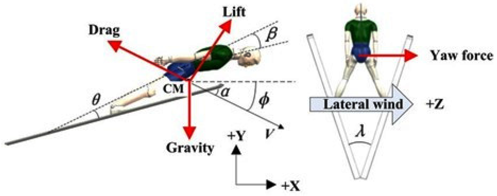
Figure 1. Posture parameters and forces acting on the multi-body system during flight. Posture parameters include flight speed V, attack angle ϕ, angle between velocity and skis α, skis opening angle λ, angle between body and skis θ, bending angle of upper body β. Forces include drag, lift, yaw force and gravity.
Preprints 96154 g001
Figure 2. Computational domain.
Preprints 96154 g002
Figure 3. Mesh distribution. (a) Volume mesh, (b) and (c) Surface mesh on the athlete.
Preprints 96154 g003
Figure 4. Change curves of aerodynamic characteristics under different lateral wind conditions. (a) The temporal changes of total lift, total drag, pitch moment, athlete’s lift, athlete’s drag and athlete’s pitch moment. (b) The temporal changes of yaw force, yaw moment, roll moment, athlete’s yaw force, athlete’s yaw moment and athlete’s roll moment.
Preprints 96154 g004
Figure 5. Change curves of aerodynamic characteristics under different yaw rotation angles. (a) The temporal changes of total lift, total drag, total lift-to-drag ratio, pitch moment, yaw force, yaw moment and roll moment. (b) The temporal changes of athlete’s lift, athlete’s drag, athlete’s pitch moment, athlete’s yaw force, athlete’s yaw moment and athlete’s roll moment. (c) The temporal changes of skis’ lift, skis’ drag, skis’ pitch moment, skis’ yaw force, skis’ yaw moment and skis’ roll moment.
Preprints 96154 g005
Figure 6. Change curves of aerodynamic characteristics under different roll rotation angles. (a) The temporal changes of total lift, total drag, total lift-to-drag ratio, pitch moment, yaw force, yaw moment and roll moment. (b) The temporal changes of athlete’s lift, athlete’s drag, athlete’s pitch moment, athlete’s yaw force, athlete’s yaw moment and athlete’s roll moment. (c) The temporal changes of skis’ lift, skis’ drag, skis’ pitch moment, skis’ yaw force, skis’ yaw moment and skis’ roll moment.
Preprints 96154 g006
Figure 7. Flow field form under lateral wind conditions.
Preprints 96154 g007
Figure 8. Flow field form under different yaw rotation angles.
Preprints 96154 g008
Figure 9. Flow field form under different roll rotation angles.
Preprints 96154 g009
Table 1. Results of Grid-independency Test.
Discrete scheme 1 Discrete scheme 2 Discrete scheme 3 Discrete scheme 4
Total grid (million) 10 14.66 19.87 28.38
Lift-to-drag 1.949 1.948 1.951 1.949
Table 2. Posture parameters and calculation conditions during flight.
Parameters Lateral wind condition Yaw rotation conditions Roll rotation conditions
Flight speed (m/s) 29 29 29
Attack angle (°) 35 35 35
Angle between velocity and skis (°) 35 35 35
Skis opening angle (°) 28 28 28
Angle between body and skis (°) 16 16 16
Bending angle of upper body (°) 18 18 18
Lateral wind speed (m/s) 0/1.5/3.0/4.5/7.5/10.5/13.5 0 0
Yaw rotation angle (°) 0 0/2.5/5/7.5/10/12.5/15 0
Roll rotation angle (°) 0 0 0/2.5/5/7.5/10/12.5/15
Note: The calculation conditions of lateral wind speed include 0m/s, 1.5m/s, 3.0m/s, 4.5m/s, 7.5m/s, 10.5m/s and 13.5m/s. The calculation conditions of yaw rotation angle include 0°, 2.5°, 5°, 7.5°, 10°, 12.5° and 15°, and the calculation conditions of roll rotation angle include 0°, 2.5°, 5°, 7.5°, 10°, 12.5° and 15°.
Table 3. Results of aerodynamic characteristics under different lateral wind conditions.
Wind speed (m/s) Total lift (N) Total drag (N) Pitch moment (N·m) Yaw force (N) Yaw moment (N·m) Roll moment (N·m)
0 297.6 151.04 -109.34 0 0 0
1.5 298.15 151.54 -109.47 1.05 0.25 -0.31
3 299.79 153.01 -109.86 4.22 1.01 -1.25
4.5 302.53 155.48 -110.51 9.48 2.27 -2.8
7.5 311.29 163.36 -112.59 26.31 6.32 -7.8
10.5 324.43 175.2 -115.7 51.58 12.38 -15.23
13.5 341.96 190.98 -119.86 85.27 20.46 -25.27
Table 4. Results of aerodynamic characteristics under different yaw rotation angles.
Yaw rotation angle (°) Total lift (N) Total drag (N) Total lift-to-drag ratio Pitch moment (N·m) Yaw force (N) Yaw moment (N·m) Roll moment (N·m)
0 297.60 151.04 1.970 -109.34 0.00 0.00 0.00
2.5 297.32 153.05 1.943 -109.44 8.78 2.16 -1.67
5 296.47 155.87 1.902 -109.58 15.89 4.27 -3.07
7.5 295.05 159.97 1.844 -109.77 24.89 6.78 -5.26
10 293.08 166.94 1.756 -110.10 34.07 10.53 -8.34
12.5 290.55 175.68 1.654 -110.56 45.12 15.22 -12.26
15 287.46 187.75 1.531 -110.93 56.30 21.63 -17.37
Table 5. Results of aerodynamic characteristics under different roll rotation angles.
Roll rotation angle (°) Total lift (N) Total drag (N) Total lift-to-drag ratio Pitch moment (N·m) Yaw force (N) Yaw moment (N·m) Roll moment (N·m)
0 297.60 151.04 1.970 -109.34 0.00 0.00 0.00
2.5 295.07 150.65 1.957 -107.92 -12.33 -2.91 2.04
5 291.19 149.32 1.950 -105.53 -28.72 -6.47 4.53
7.5 285.46 147.27 1.938 -102.43 -42.07 -11.17 7.82
10 277.25 145.54 1.905 -99.14 -54.08 -16.93 11.85
12.5 262.82 142.88 1.839 -94.68 -69.81 -25.45 17.81
15 245.78 139.13 1.766 -89.83 -83.90 -37.77 23.59
Disclaimer/Publisher’s Note: The statements, opinions and data contained in all publications are solely those of the individual author(s) and contributor(s) and not of MDPI and/or the editor(s). MDPI and/or the editor(s) disclaim responsibility for any injury to people or property resulting from any ideas, methods, instructions or products referred to in the content.
Copyright: This open access article is published under a Creative Commons CC BY 4.0 license, which permit the free download, distribution, and reuse, provided that the author and preprint are cited in any reuse.
Prerpints.org logo

Preprints.org is a free preprint server supported by MDPI in Basel, Switzerland.

Subscribe

© 2024 MDPI (Basel, Switzerland) unless otherwise stated