1. Introduction
Transformer equipment in the power transmission system is mainly composed of metal materials (e.g., windings and cores) and insulating materials. The insulation system plays an important role in protection and isolation for the operation of the equipment. However, during the operation of the equipment, the insulation system is exposed to the interaction of electricity, temperature, mechanical stress and chemical reactions for a long time, inevitably leading to the gradual deterioration of the insulation performance. Meanwhile, the weak links of the system may lead to insulation defects. Without timely detection and appropriate repair measures, the defects may develop and expand continuously, and even cause accidents of equipment insulation breakdown, which not only brings significant economic losses to users, but may also destroy the stable operation of the entire power system. In terms of the maintenance work for normal operation of the transformer, internationally, in the early days, repair work was performed only if an accident occurred. Afterwards, in order to prevent such sudden accidents, maintenance work was carried out at fixed time. Regular inspections and relevant tests are effective on detecting equipment defects and reducing accidents to some extent. However, the actual operating status of the equipment is not fully considered, and excessive testing of the equipment may be performed. This not only results in a waste of manpower and material resources, but also, as the voltage level increases, and the equipment capacity increases, some problems in periodic detection may be exposed. Therefore, the periodic maintenance system is still unable to effectively prevent accidents in fault warning and detection.
The power transmission system transformers are mainly used in ultra-high voltage, primary and distribution substations. Based on circuit design and user needs, they can be divided into single-phase and three-phase types. Their insulation systems are mostly oil-paper composite insulation, supplemented by Sulfur hexafluoride (SF6) gas and EPOXY mold casting, requiring high safety, high reliability, maintenance-free, easy installation and meeting environmental protection, so as to meet environmental and economic effects. Therefore, the diagnosis and detection of equipment faults not only play a very important role in the safe and stable operation of the power system, but are also an important means of safety protection for inspection personnel and residents around the substation. This study focused on transformer equipment and develops a long-term online insulation aging monitoring and diagnosis system, and uses the network transmission technology to make it easy to be installed on the existing transformer equipment.
Currently, commercial online insulation diagnosis systems suitable for transformer equipment in the world are rare and expensive. There are not yet products in relation to the diagnostic system with long-term observation and simultaneous monitoring of dual sensors (ultrasonic and high-frequency current transformers) to facilitate complementation and comparison, effectively eliminate noise, determine the fault types, and estimate insulation aging status. Therefore, this paper discusses and analyzes the sensitive ultrasonic and high-frequency current transformer pulse methods for partial discharge detection in transformers, and uses statistical and electrical operations as a method of extracting features and uses neural networks as classification and identification systems. In addition, the conclusions drawn from this experiment can be used for mutual comparison when combined with other methods for simultaneous detection, hoping to achieve a more accurate diagnostic technology for detecting the insulation aging state.
Some insulation deteriorations of transformer equipment are immediate changes caused by natural or man-made disasters, such as lightning surges, switching surges, and nonlinear resonance. At the same time, some are the aging results accumulated during long-term operation. Therefore, if the immediate and cumulative effects of deterioration can be observed at the same time, the impact of insulation breakdown on the entire power supply system can be prevented more comprehensively. Therefore, this study aims to develop a set of transformer operating state monitoring and diagnosis system. The proposed system is divided into two major parts according to functions, namely the operation monitoring and immediate warning unit and the central monitoring unit. The block diagram of the operation monitoring and immediate warning unit placed in the transformer equipment for a long time is shown in
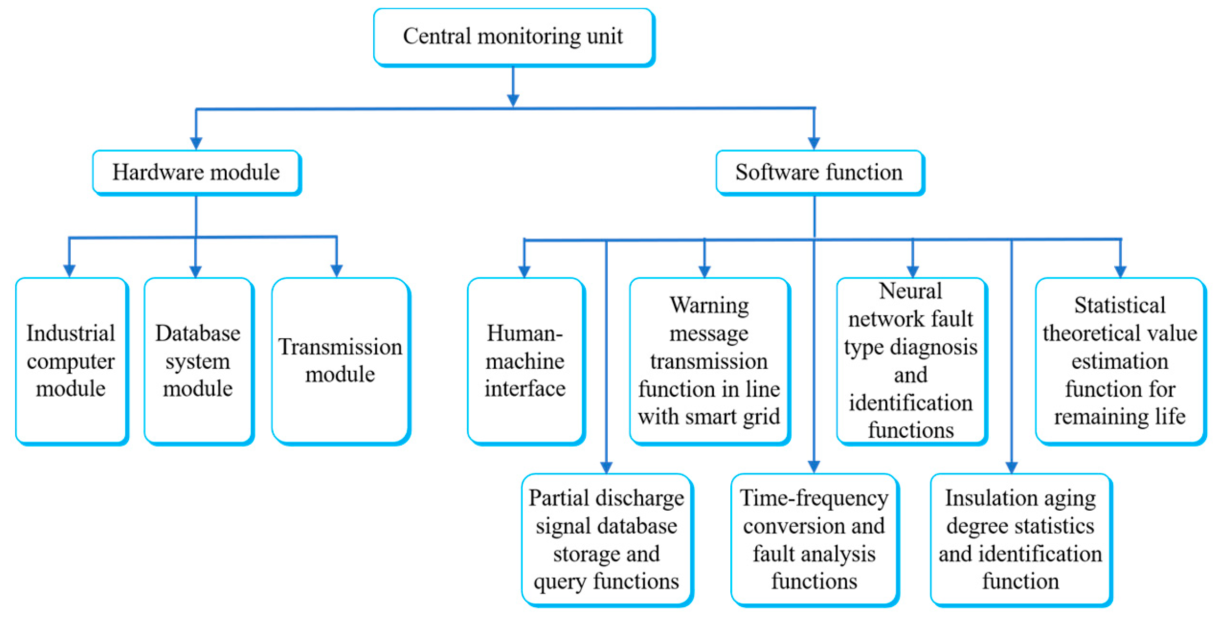
Figure 1. It consists of an embedded computing module, a sensor module and a transmission module. It captures the partial discharge ultrasonic signals of three channels online in real time and the high frequency current transformer pulse signals of five channels (including self-made transformer three-phase high-voltage cable inlet, three channels of high-frequency inductive partial discharge sensor, and self-made high-frequency current transformer, two channels of partial discharge pulse signals for measuring shell and core grounding wire) supplemented by software and hardware interference and noise elimination mechanisms. Through the capture of partial discharge characteristic signals, the internal insulation and operating state faults can be analyzed and judged immediately. The original ultrasonic wave and high-frequency current transformer pulse signals are fed back to the central monitoring unit through the communication module, so as to identify the fault types and perform long-term analysis of insulation aging conditions. The other part of this system is the central monitoring unit. The block diagram is shown in
Figure 2. It consists of an industrial computer and a transmission module. It collects and stores the ultrasonic and high-frequency current transformer pulse signals from each operation monitoring and immediate warning unit, performs software-based signal noise and interference elimination, and then uses neural networks to identify the fault type to assist the operation and maintenance personnel in quick and correct handling. Secondly, according to the analysis of the measured spectra, the signal patterns of the transformer equipment insulation aging process can be made into a database. The feature extraction of the equipment insulation aging process can be used to establish a digital assessment and identification system for the transformer equipment insulation aging status based on ultrasonic and high-frequency current transformer pulse methods. The remaining life of the equipment is then analyzed, so as to estimate the damage status of the equipment and reduce possible power outage crises.
2. Literature Review
The power transmission system is constructed from numerous power transmission equipment, including towers, lines (overhead and underground cables), transformers, lightning arresters, switch boxes (air-sealed) switches, capacitors, and inductors. The insulating material status of these equipment acts as an important indicator of the equipment operation quality. Therefore, the insulation status monitoring of insulating materials and the assessment of aging phenomena have become one of the keys to judging the performance and life of power transmission system equipment [
1,
2]. Using detection technology to know the insulation state of equipment is an important key to judging the operating state of power transmission system equipment, so it is a subject worthy of in-depth study. At present, the methods for detecting the transformer insulation and operating states include gas-in-oil analysis, partial discharge detection, insulation resistance method, and dissipation factor method (Tan Delta).
The partial discharge phenomenon is an important observation indicator of the initial deterioration of the insulation system, as well as the most effective method to judge the abnormality of high-voltage insulating materials. It is suitable for equipment with high voltage and above [
3,
4,
5]. If it is used properly, the insulation deterioration can be effectively detected at the initial stage. The most familiar partial discharge detection methods are: pulse current method, ultrasonic detection method, and Ultra High Frequency (UHF) detection method, which can be used in the transformers using insulating oil as insulating material, epoxy resin insulating materials, and can be used in high-voltage equipment using SF6 as insulating gas, as well as in the development of online monitoring systems. In the past, the limitations of partial discharge detection technology were that the detection instruments could not perform quantification and numerical calculations. Therefore, it has not been the focus of development until Ward [
6] used computer for quantification in 1992. Along with the advancement of computer technology, the quantification process and the stored partial discharge detection technology were improved to a higher level [
7,
8,
9], initiating a new era of partial discharge detection technology. Hence, more scholars took part in research, and many more excellent detection systems and analysis technologies were developed.
There are many representative articles on using partial discharge to detect the insulation state of transformer equipment [
10,
11,
12,
13,
14,
15,
16,
17,
18,
19,
20,
21], but most of them focused on offline detection, the online partial discharge of transformer equipment was seldom discussed. In addition, most of the analysis methods only use complex signal analysis rules to analyze and determine whether it is an insulation fault condition in the inspection mode of a single pressure test. There is no dual structure as proposed in this plan, and there are immediate warning and long-term trend observation method. Two partial discharge sensors are used at the same time for complementary and repeatable deterministic partial discharge diagnosis. In addition, most of the studies only performed fault diagnosis, and there was no publication about the insulation aging state estimation. Therefore, the framework and concepts proposed in this paper are still innovative in the world.
The original measurement signal capacity of the partial discharge spectrum is large, so that the data may not be analyzed effectively. Therefore, a method of extracting features has been developed. The common methods for extracting features are: statistical operation [
22], fractal dimension [
22,
23], and Weber function [
24]. The method of extracting features is combined with the identification system. The common identification methods use fuzzy identification, Artificial Neural Network and probabilistic classification method as identification systems. It can be known from literature references that the artificial neural network is one of the effective identification methods [
23,
25], and then the automation of partial discharge spectrum identification began. However, with the advancement of electronic technology and the development of sensor technology, optical fiber technology, computer technology, and information processing technology, and their wide application in various fields, online monitoring of transformers has gradually become possible. The online monitoring system of transformers refers to the system which continuously checks and judges the equipment state during the equipment service period, and can predict the equipment state development trend. The research issues about online monitoring technology generally include: the selection of online monitoring method, the transmission, processing and storage of monitoring information, the acquisition of fault characteristic quantities, the analysis of fault state, and the prediction of insulation aging. Therefore, the online monitoring technology is studied actively in the world, hoping to make an important impact on improving the operation and maintenance level of power equipment, discovering hidden accident hazards in real time, and reducing the probability of accidents.
3. Methods
3.1. Sensor selection and design
The detection of partial discharge is expressed by the physical quantity generated by the equipment. The common evaluation methods include ultrasonic method, ultra-high frequency method, current pulse method, and electromagnetic radiation method. The ultra-high frequency and electromagnetic radiation sensors can hardly detect the internal partial discharge signals from the metal casing of transformers, so they are not suitable for measuring partial discharge phenomena in transformers. The ultrasonic sensor can measure all partial discharge phenomena, including the discharge between opposite phase windings, but its sensitivity is low, it is workable only if the discharge is obvious. The high-frequency current transformer has higher sensitivity, any slight discharge can be measured, but must be measured through the ground wire. Therefore, the two sensing methods have their own advantages and disadvantages. This study used different sensor in combination, and applied the ultrasonic and high-frequency current transformer methods to develop an online operating state monitoring and diagnosis system based on transformer equipment.
In order to comprehensively prevent the impact of insulation breakdown, this system uses the partial discharge ultrasonic signals of three channels and the high-frequency current transformer pulse signals of five channels. This study used three channels to detect partial discharge ultrasonic signals. Due to the general power transmission system transformer used in Taiwan, if the structure is divided into left and right windings and oil tanks, which are connected by a common pipe in the middle, an ultrasonic sensor is installed on the left and right windings and the middle pipe, possible defects could be taken into account more comprehensively. If there are no left and right windings, an ultrasonic sensor can be placed in the middle of the RST three-phase winding. In addition, the five-channel high-frequency current transformers are divided into two classes. Class 1 is the high-frequency inductive partial discharge sensor installed on the 3-phase high-voltage cable inlet, it uses the principle of air-core inductance. When partial discharge is generated, pulse current will occur on the RST phase power supply line, which would produce instantaneous changes in the spatial magnetic field, so that the high-frequency inductive partial discharge sensor induces pulse voltage, the power cable is tied with a plastic tape before use. The other class is the pulse current transformer with a high-frequency core, which is the general commercial high-frequency current transformer pattern for measuring partial discharge signals. This type of sensor is installed on the transformer case and core ground wire to measure partial discharge pulse signals.
3.2. Experimental Instruments
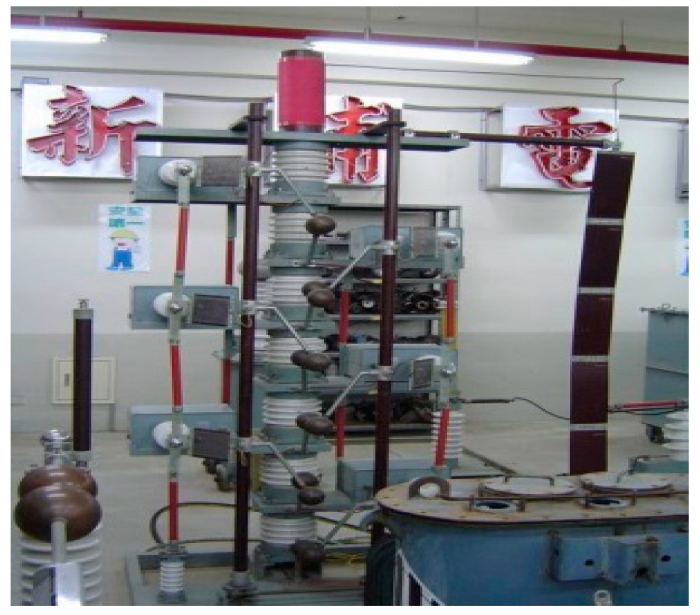
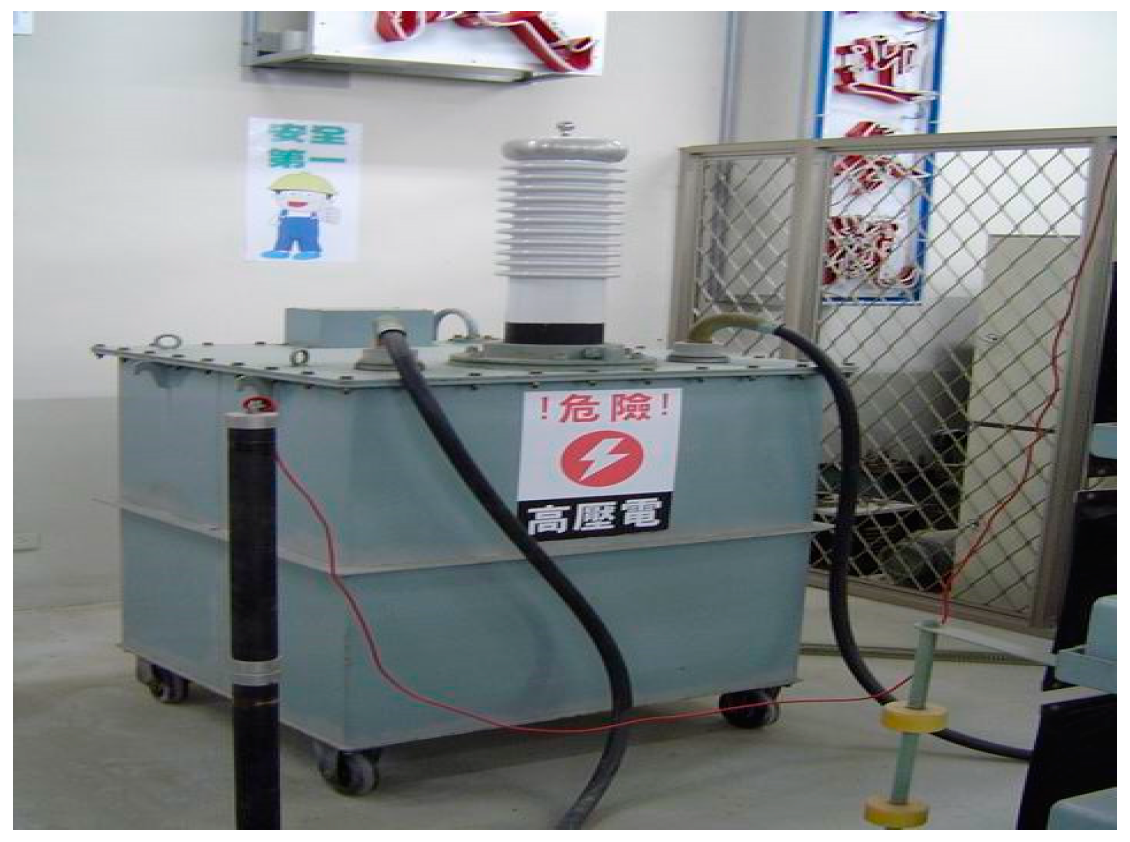
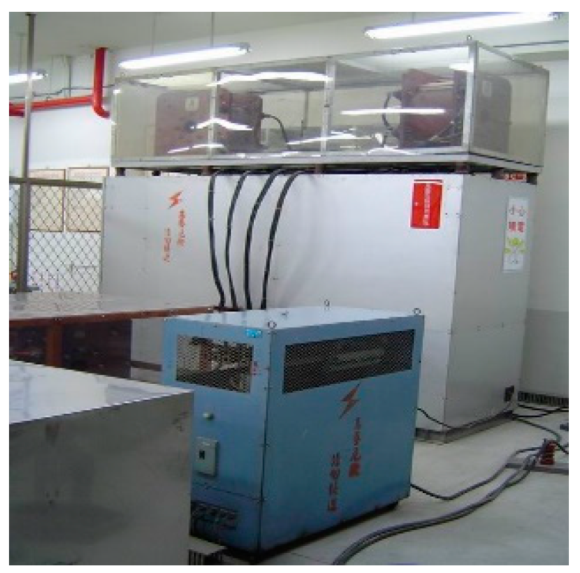
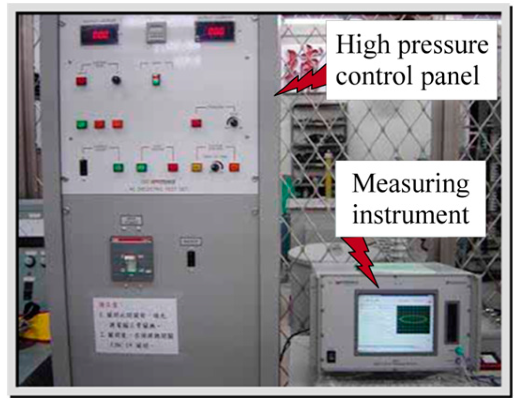
The high-voltage laboratory experimental instruments for transformer partial discharge measurement include an impulse voltage generator that can be boosted to 300KV (
Figure 3), a booster that can generate AC 150KV (
Figure 4), and a large current testing device, which provide a very convenient environment for motor supercharging, overload and insulation detection tests (
Figure 5), a digital partial discharge detector, including a high-voltage generating device (
Figure 6), a vibration sensor and high-speed A/D acquisition card.
3.3. Insulation aging feature extraction
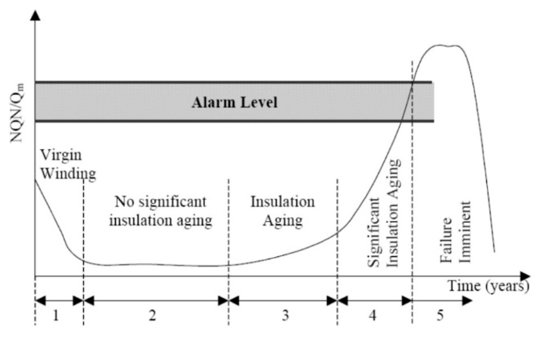
The original signal spectrum of transformer partial discharge has multiple and complex information. The features of insulation aging must have simple patterns and are easy to distinguish, that is beneficial to the accuracy of the system in identifying the characteristic quantities. Therefore, the data obtained from the partial discharge test are used for HHT transformation and statistical analysis. The statistical operation values such as skewness, protrusion, number of local peaks, discharge asymmetry, phase asymmetry, cross-correlation factor, phase median, and corrected correlation factor can be obtained. The feature values of the transformer equipment insulation aging process can be screened out by using the physical property values obtained from the operation values and tests. Based on this, the physical data (e.g. the energy in ultrasonic waves) obtained from the accelerated aging test, and the statistical operation values (e.g. skewness), are made into a curve with the X axis as the time axis, which is compared with the traditional electrical insulation aging curve, as shown in
Figure 7. If the two curves are similar, the physical characteristics or statistics represented by the data can be used as insulation aging characteristics of transformer equipment.
3.4. Convolutional neural network identifies fault type
The artificial neural network has robustness, correctness and usability in identification and prediction, and is widely used in many different fields. This study used the artificial neural network as a tool to identify transformer fault warning, fault type and insulation aging. The applicable network model and the input-output relationship are shown in
Figure 8. The input feature value is the waveform measured by the sensor. The feature extraction is performed based on statistical rules and electrical characteristics. The output is the possible fault type and the degree of insulation aging of the transformer.
First, the size of the input image is 160×120. The Layer 1 of the model is a convolution layer, and 25 kernels extract 5×5. The Layer 2 of the model is a pooling layer, 2×2 compression. The Layer 3 of the model is a convolution layer, 50 kernels extract 5×5. The Layer 4 of the model is a pooling layer, 2×2 compression. The Layer 5 of the model is a convolution layer, 100 kernels extract 5×5. The Layer 6 of the model is a pooling layer, 2×2 compression. The Layer 7 of the model is a fully connected layer with 500 kernels. The Layer 8 of the model is a fully connected layer with 250 kernels. The Layer 9 of the model is a fully connected layer for classification, and the expected output classification result is expected. In addition, the system was in the system self-learning and improvement adjustment stage during the first 14 days of application, as shown in
Figure 9. At this stage, the system assumes that the transformer is in good condition, so it can overcome the problem of insufficient fault samples, using the advantages of neural networks to learn online in real time to avoid misjudgment of normal operating state.
4. Results
4.1. Design of functional interface of central monitoring unit
The central monitoring unit uses Labview to design a graphical user interface to make signal acquisition, analysis and storage more user-friendly. The system can visualize the operation and conduct preliminary analysis of the measured signals in real time and synchronously, including harmonic analysis, filtering and frequency analysis. The displayed menus can be divided into two main types. The first type is analysis and statistical charts for professional use, which is suitable for professional maintenance personnel and operators to perform analyses and statistics. The second type is the integrated simplified status display interface, which is a simple bar-type display menu for on-site operators and users to easily know the operating state of the transformer and possible fault warnings. The state warning levels planned in this unit are shown in
Table 1.
4.2. Design of display interface of operation monitoring and immediate warning unit
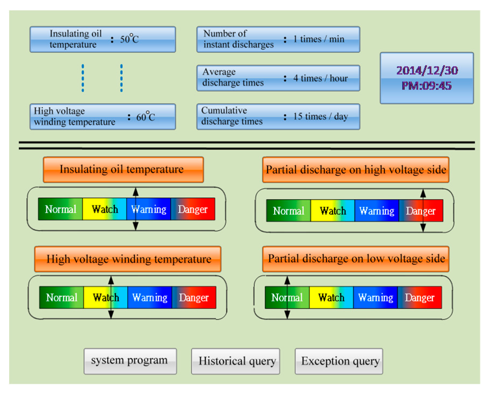
The operation monitoring and immediate warning unit combines the signal capture of sensors with the temperature monitoring of the transformer as the basis of operating state display and early warning judgment. This unit is designed with a simple and easy-to-understand display interface, so that the inspection and maintenance and operating personnel can easily know the insulation and operating state of the transformer, as shown in
Figure 10. In addition, the interface for developing the transformer partial discharge operation monitoring and immediate warning unit includes the main menu, manual automatic detection and filtering menu, partial discharge monitoring menu and partial discharge analysis menu. The functions of the menus are described below:
4.2.1. Main menu
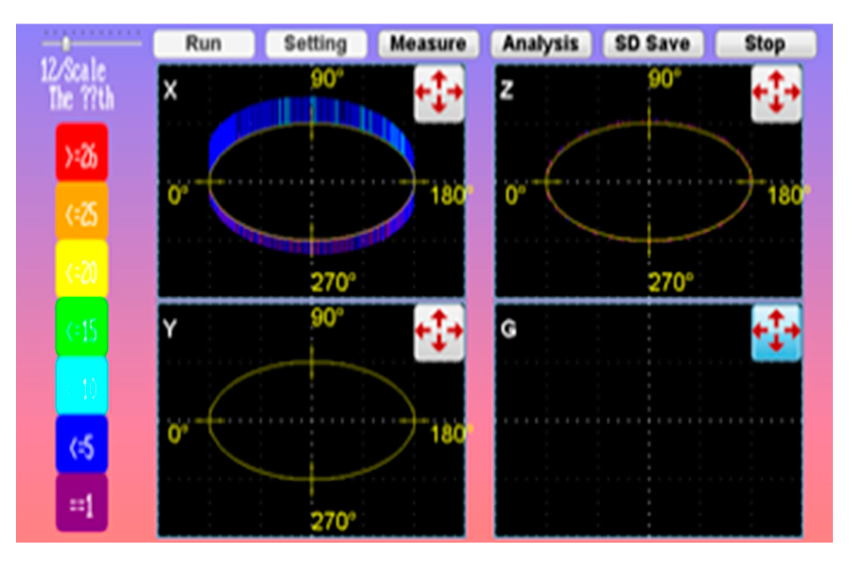
The users perform interactive instructions and measurement by touching the screen. The main screen is shown in
Figure 11. There are seven interactive buttons and four small windows for displaying the three-phase voltage and ground voltage. The measurement results are displayed automatically after measurement. The length of the value represents the maximum discharge amount; the color represents the maximum discharge number. When the measured value is too small or too large, the users can adjust the appropriate value magnification through the scroll bar on the upper left to facilitate observation and increase discrimination. The histogram on the left provides color judgment of the discharge number. The mode of Setting and the frequency of the digital filter must be set before starting, the Measure is pressed for measurement, the result is displayed immediately after measurement. The users can master the usage of the equipment at any time through measurement and observation. Finally, the measured data are stored in the SD card, so as to know the abnormal condition of the equipment and provide reference for historical analysis and maintenance schedule in the future.
4.2.2. Manual and automatic detection and filtering menu
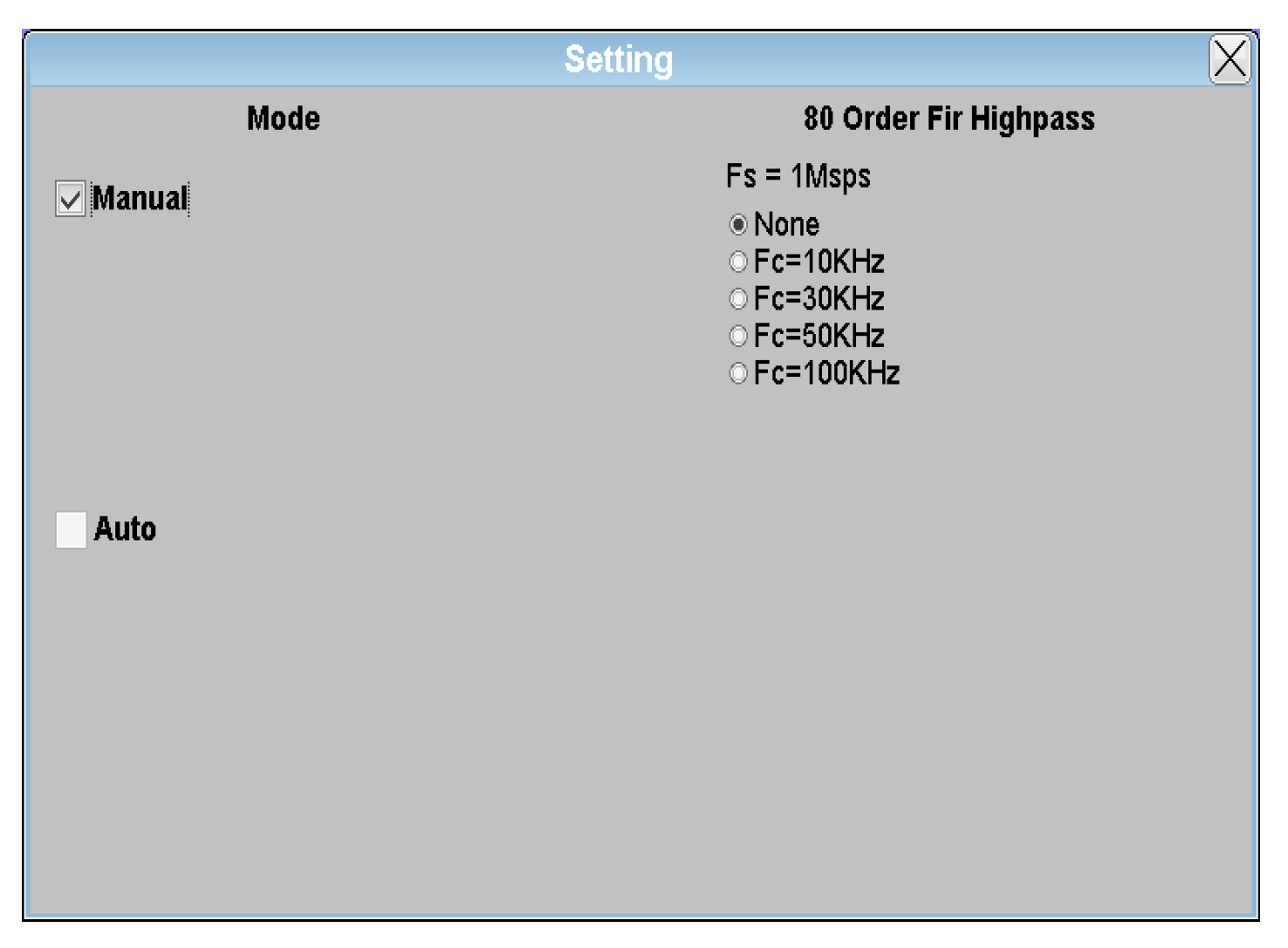
The users can perform appropriate measurement by selecting the mode, as shown in
Figure 12. In manual mode, the users must interact with the touch screen step by step to obtain measurement information and learn the device usage status in real time. For long-term monitoring, the automatic mode can be selected. The monitoring unit measures once every minute and automatically store the measurement results in the SD card. The users only need to watch and check periodically to achieve the automatic function. In the measurement process, in order to avoid noise interference which reduces the accuracy of system judgment, resulting in misjudgment, the users can first perform digital filtering through appropriate selection of the digital filter to filter out the noise, so that the system measures clean signals, the measurement quality is improved, and the numerical analysis is more accurate.
4.2.3. Partial discharge monitoring menu
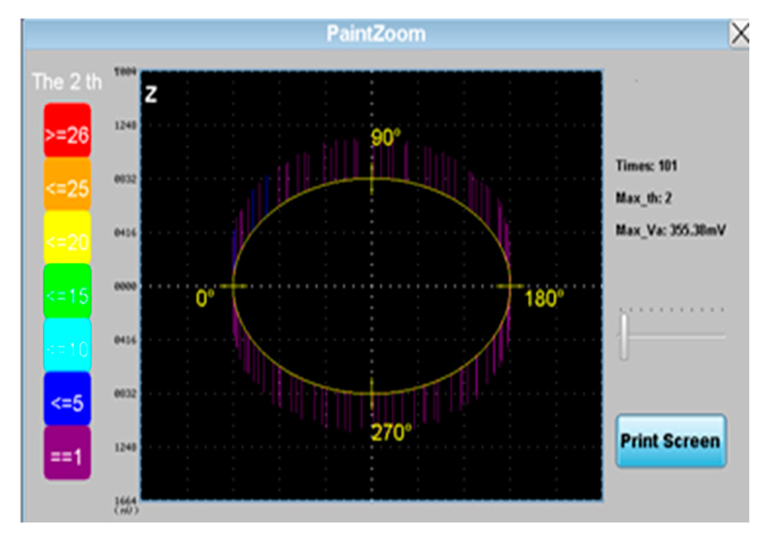
If the users want to view single-phase data, the one-way angle numerical diagram is displayed immediately after PaintZoom is pressed. The measurement parameters in this phase include the total discharge number, the maximum discharge number, and the maximum discharge amount, for the users to perform partial discharge judgment and analysis, as shown in
Figure 13. The histogram on the left is the color indicator of the discharge number, different colors are used to warn the users of current usage of the equipment, so as to avoid unexpected equipment faults.
4.2.4. Partial discharge analysis menu
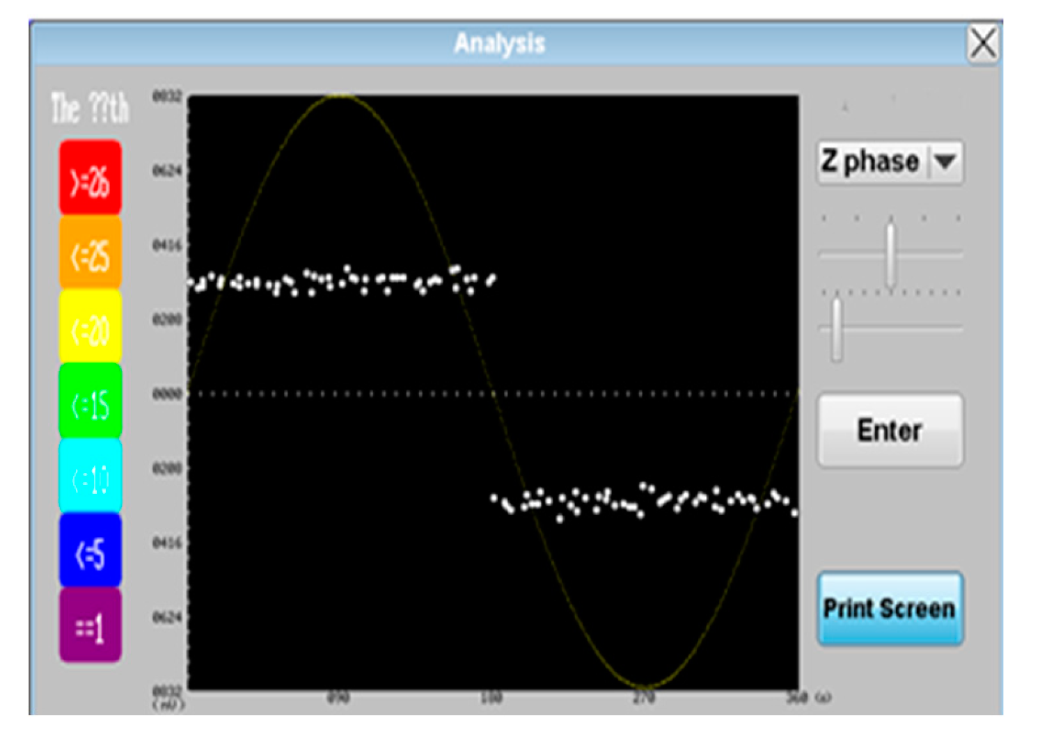
After the measurement, the users can press Analysis for further analysis and judgment. As shown in
Figure 14, this function allows the users to observe the usage of the equipment from different angles, and use the discharge amount, number and distribution trend at the judgment angle to analyze the type of partial discharge, so as to implement correct maintenance. This setting displays the angle trend chart of a single phase each time. The users can make flexible adjustment through the scroll bar to facilitate observation and analysis. To record and save, Print Screen can be pressed to take pictures and save them in the SD card.
Figure 10.
Human-machine display interface of operation monitoring and immediate warning unit.
Figure 10.
Human-machine display interface of operation monitoring and immediate warning unit.
Figure 12.
Manual and automatic detection and filtering menu.
Figure 12.
Manual and automatic detection and filtering menu.
Figure 13.
Partial discharge monitoring menu.
Figure 13.
Partial discharge monitoring menu.
Figure 14.
Partial discharge analysis (PRPD diagram) menu.
Figure 14.
Partial discharge analysis (PRPD diagram) menu.
5. Discussion
The operating state monitoring and diagnosis system for high-voltage equipment developed in this study has the following characteristics:
− Low cost, and mass installation: Currently, the price of a high-frequency current transformer for measuring partial discharge on the market is about NTD 150,000. This study developed a high-frequency current transformer with high sensitivity for partial discharge signals, and the cost can be controlled below NTD 5000. In addition, the operation monitoring and immediate warning unit uses a self-developed embedded system, which greatly reduces the cost of the detection system and facilitates installation in a large number of measured transformers.
− Easy installation, not influencing the operation of the original equipment, and non-intrusive detection: This paper uses ultrasonic and high-frequency current transformer to detect possible partial discharge signals. The non-invasive detection method is used, the sensors are installed without power outage, and can be completed through simple external installation process, so the installation is quite easy, and does not affect the normal operation of the transformer to be tested.
− Comprehensive faults are taken into account as possible to prevent them: This paper uses ultrasonic and high-frequency current transformer sensors to monitor the occurrence of partial discharge in many aspects. Meanwhile, the master-slave architecture of the operation monitoring and immediate warning unit and the central monitoring unit is used, with appropriate diagnosis and identification algorithms, possible transformer faults can be taken into account as possible to prevent accidents before they happen.
− The detection system can have signal processing capabilities to avoid frequent false alarms: Both the operation monitoring and immediate warning unit and the central monitoring unit have appropriate fault diagnosis and identification signal analysis technologies and algorithms, which can avoid the possibility of false alarms caused by judging partial discharge only based on the size of the discharge signal.
− Long-term monitoring, providing aging trend reference: The central monitoring unit can record the discharge signals transmitted by the operation monitoring and immediate warning unit for a long time, and analyze the insulation aging degree, which is helpful to predict the life of the transformer in advance and conduct asset management.
6. Conclusions
This study developed a set of operating state monitoring and diagnosis system for transformers, through theoretical analysis and study of spectra, with data acquisition and fault type analysis of graphic-controlled human-machine interface. An intelligent online real-time state detection and fault warning system was developed, supplemented by verification procedures to confirm the feasibility of the theory, so as to provide the operating state monitoring and preventive accident detection for the transformers in the transmission system.
At present, the online fault detection products for partial discharge of high-voltage transformers in the world are relatively expensive, and this type of fault diagnosis methods mostly uses a single feature detection, so there is a risk of misjudgment or relatively low accuracy. The detection system developed in this study only costs about one-tenth of the price of related international products. The developed transformer operating state monitoring and partial discharge fault diagnosis system is used for comprehensive feature detection of two methods, including: partial discharge ultrasonic signal detection technology and high-frequency current transformer pulse signal detection technology. Combined with the advantages of detection technology, comprehensive detection and judgment of high-voltage transformer equipment components are performed, favorable for improving the accuracy of analysis. This study thus made significant contributions to improving the stability of power transmission and distribution system ends, reducing the probability of abnormal faults, optimizing the operating efficiency of the entire power transmission and distribution system, reducing the costs of maintenance and testing, and guaranteeing power quality and power supply safety.
Author Contributions
This research article contains two authors, including H.L.S. and F.H.C. F.H.C. and H.L.S. jointly design the overall architecture and related algorithms, and also conceived and designed the experiments, however, H.L.S. coordinated the overall plan and direction of the experiments and related skills; F.H.C. and H.L.S. not only contributed analysis tools, but also analyzed the data; F.H.C. performed the experiments; and H.L.S. wrote this paper and related reply.
Funding
This research was funded by National Science and Technology Council, Taiwan, grant number “NSTC 112-2221-E-262-001-MY2”.
Conflicts of Interest
The authors declare no conflict of interest.
References
- Agarwal, V.K. et al. ”The mysteries of multifactor aging. ” IEEE Electrical Insulation Magazine 1995, 11, 37–43. [Google Scholar] [CrossRef]
- Lin, Y.H., Wu, R.N., Chung, I.H. Novel trend of l shape in PD pattern to judge the appropriate crucial moment of replacing cast-resin current transformer.” IEEE Transactions on Dielectrics and Electrical Insulation. 2008, 15, 292–301. [CrossRef]
- Farag, A.S. , Shewhdi, M. H., Jin, X., Wang, C., Cheng, T.C., Dong, X., Gao, S., Jing, W., & Wang, Z. “On-line partial discharge calibration and monitoring for power transformers.” Electric Power Systems Research, 1999, 50, 47–54. [Google Scholar] [CrossRef]
- Yue, B. , Chen, X, Cheng, Y., Song, J., & Xie, H. „Diagnosis of stator winding insulation of large generator based on partial discharge measurement.” IEEE Transactions on Energy Conversion. 2006, 21, 387–395. [Google Scholar] [CrossRef]
- Karthikeyan, B. , Gopal, S. , & Venkatesh, S. “Partial discharge pattern classification using composite versions of probabilistic neural network inference engine.” Expert Systems with Applications. 2008, 34, 1938–1947. [Google Scholar] [CrossRef]
- Barry, H. Ward, “Digital Techniques for Partial Discharge Measurements,” IEEE Transactions on Power Delivery 1992, 7, 469-479. [CrossRef]
- E. Gulski, “Computer-aided Measurement of Partial Discharges in HV Equipment,” IEEE Transactions on Electrical Insulation. 1993, 28, 969–983. [CrossRef]
- James, R.E. & Phung, B. T. „Development of computer-based measurements and their application to PD pattern analysis.” IEEE Transactions on Dielectrics and Electrical Insulation. 1995, 2, 838–855. [Google Scholar] [CrossRef]
- Tanaka, T. “Partial discharge measurement and interpretation. IEE Proceedings Science, Measurement and Technology,”. 1995, 142, 46–50. [Google Scholar] [CrossRef]
- S. Farag, M. H. Shewhdi, X. Jin, C. Wang, T. C. Cheng, X. Dong, S. Gao, W. Jing and Z. Wang, “On-line partial discharge calibration and monitoring for power transformers”, Electric Power Systems Research, 1999, 50, 47–54. [CrossRef]
- H. Ward, “A survey of new techniques in insulation monitoring of power transformers”, IEEE Electr. Insul. Mag, 2001, 17, 16–23.
- J. R. Nino and A. Pascacio, “Acoustic measuring of partial discharge in power transformers”, Measurement Sci. Techn. 2008, 20, 115708. [Google Scholar] [CrossRef]
- H. Okubo and N. Hayakawa, “A novel technique for partial discharge and breakdown investigation based on current pulse waveform analysis”, IEEE Trans. Dielectr. Electr. Insul. 2005, 12, 736–744. [Google Scholar] [CrossRef]
- M. D. Judd, L. Yang and I. B. B. Hunter, “Partial discharge monitoring for power transformers using UHF sensors part 1:sensors and signal interpretation”, IEEE Elect. Insul. Mag. 2005, 21, 5–14. [Google Scholar] [CrossRef]
- M. Wang, A. J. Vandermaar and K. D. Srivastava, “Review of condition assessment of power transformers in service”, IEEE Elect. Insul. Mag. 2002, 18, 12–25. [Google Scholar] [CrossRef]
- Cavallini, G. C. Montanari and M. Tozzi, “PD apparent cgarge estimation and calibration : a critical review”, IEEE Trans. Dielectr. Electr. Insul. 2010, 17, 198–205. [Google Scholar] [CrossRef]
- P. J. Moore, I. E. Portugues and A. Glover, “Radiometric location of partial discharge sources on energized high voltage equipment”, IEEE Trans. Power Del. 2005, 20, 2264–2272. [Google Scholar] [CrossRef]
- S. M. Markalous, S. Tenbohlen and K. Feser, “Detection and location of partial discharges in power transformers using acoustic and electromagnetic signals”, IEEE Trans. Dielectr. Electr. Insul. 2008, 15, 1576–1583. [Google Scholar] [CrossRef]
- J. R. Serrano, M. V. R. Moreno, J. Posada, J. M. M. Tarifa, G. Robles and J. A. G. Souto, “Electro-acoustic detection, identification and location of partial discharge sources in oil-paper insulation systems”, IEEE trans. Dielectr. Insul. 2012, 19, 1569–1578. [Google Scholar] [CrossRef]
- E. C. Jordan and K. G. Balmain, Electromagnetic Waves and Radiating Systems, Prentice-Hall, Inc. chapter 5, 2nd ed. 1968.
- M.‐K. Chen, C.‐Y. Cheng and J.‐M. Chen, “Partial Discharge in Light-Load 161KV Power Transformer”, Int’l. Conf. Electr. Machine and Systems, (ICEMS), Paper P799-804, Wuhan, China, 2008.
- R. Candela, G. Mlrelli and R. schifani, “PD Recognition by Means of Statistical and Fractal Parameters and a Neural Network,” IEEE Transactions on Dielectrics and Electrical Insulation. 2000, 7, 87–94. [CrossRef]
- G. Mirelli and R. Schifani, “A Novel Method for the Recognition of PD Patterns by Neural Network,” Annual Report Conference on Electrical Insulation and Dielectric Phenomena. 1999, 1, 206–209. [CrossRef]
- E. A. Feilat, S. Grzybowski and P. Knight, “Accelerated Aging of High Voltage Encapsulated Transformers for Electronics Applications,” Proceedings of the 6th International Conference on Properties and Applications of Dielectric Materials 2000, 1, 209-212. [CrossRef]
- A. Krivda, “Automated Recognition of Partial Discharges,” IEEE Transactions on Dielectrics and Electrical Insulation 1995, 2, 796-821. [CrossRef]
|
Disclaimer/Publisher’s Note: The statements, opinions and data contained in all publications are solely those of the individual author(s) and contributor(s) and not of MDPI and/or the editor(s). MDPI and/or the editor(s) disclaim responsibility for any injury to people or property resulting from any ideas, methods, instructions or products referred to in the content. |
© 2024 by the authors. Licensee MDPI, Basel, Switzerland. This article is an open access article distributed under the terms and conditions of the Creative Commons Attribution (CC BY) license (http://creativecommons.org/licenses/by/4.0/).
