1. Introduction
Permanent magnet synchronous motor (PMSM) has gained widespread attention and application in high-performance speed regulation fields such as electric vehicles, CNC machine tools, and robots due to its advantages of high control accuracy, high power density, and stable operating state [
1,
2]. However, with the increasing demand for precision and stability in various industrial fields, the requirements for control systems of motor components also increased [
3,
4]. In conventional PMSM vector control, photoelectric encoders or rotary transformers are used to detect and feedback the speed and position information of the motor, in order to achieve close-loop vector control of the control system [
5]. However, in practical applications, there are special working conditions such as sensor damage or sensor installation difficulties for motors, overreliance on mechanical sensors can lead to a decrease in the reliability and precision of the entire control system, as well as reducing the space utilization rate and increasing the costs of the motor control system [
6]. Therefore, it is necessary to replace conventional mechanical sensors with a PMSM sensorless position and velocity estimation control technology to improve the control stability and ensure control accuracy of PMSM [
7,
8].
Sensorless control scheme of PMSM can be applied to multi-stage speed control occasion such as zero speed, low speed, medium speed, and high speed [
9]. When the motor is operating at zero or extremely low speeds occasions that is difficult to extract the information of useful signals. high-frequency signals include rotating high-frequency voltage signals and pulsating high-frequency voltage signal injection method are commonly used to solve this problem, and are commonly used [
10,
11]. Sensorless control for the middle or high-speed occasions of PMSM is based on its remarkable counter-electromotive force, and the observation method is often used to estimate the position and speed signals. The commonly used observation methods include flux observer, model adaptation, extended Kalman filter, and sliding mode observer [
12,
13].
Flux observer performs similarly to the linear observer in the steady state with ringing after transients are reduced [
14]. Model adaptation scheme can solve the problem that fault sensitivity of PMSM stator currents and rotor speed measurements is very low with regard to single mechanical faults [
15,
16]. The EKF is established according to the PMSM motion model to filter measurement noise and generate external disturbance estimations promptly and reduce the observed burden [
17,
18].
In the above methods, sliding mode observer has become a hot application topic for high-speed sensorless control of PMSM due to its advantages such as low accuracy requirements for modeling, insensitivity to parameter variations, and low controller burden. [
19,
20] However, due to the switching characteristics of the sliding mode observer during the control process, there may be severe chattering phenomena that can affect the control accuracy of the entire control system[
21].
In order to suppress the chattering phenomenon of sliding mode observers, this paper proposes a novel power sliding mode converging law for improvement on the basis of conventional sliding mode observer, which can effectively suppress the chattering phenomenon in sliding mode control. At the same time, in order to improve the accuracy of position and velocity estimation, a phase-locked loop (PLL) estimation algorithm was adopted to replace the conventional arctangent estimation algorithm. We analyze the stability of the system by using the Lyapunov function, and then validate the PMSM sensorless control algorithm proposed in this paper through simulation experiments. The main contributions are as follows:
A sliding mode observer scheme based on the novel power converging law is designed to reduce the chattering as well as graduate the rapid converging rate.
A PLL is adopted to replace the conventional arctangent estimation algorithm, which can enhance the estimation precision.
The whole paper is presented as follows: In
Section 2, the mathematical model of PMSM is constructed and designed. In
Section 3, a conventional sliding mode observer is employed to realize the sensorless control of PMSM. a sliding mode observer based on novel power converging is designed in
Section 4. In
Section 5, we implement several experiments to verify the effectiveness of the proposed sensorless control scheme.
Section 6 summarizes the whole paper.
2. PMSM Modelling
The voltage equation of surface-mounted PMSM in two-phase stationary α-β coordinate system is:
Simplify equation (1) and obtain the current equation as follows:
The counter-electromotive force equation can be expressed as:
where
,
is counter-electromotive force on
α-β axis respectively;
,
is stator voltage on
α-β axis respectively;
is electric angular velocity;
is winding inductance;
is winding reluctance.
It can be seen from equation (3) that the counter-electromotive force of the motor is directly related to the rotor position and speed information. The mathematical model of the PMSM can be reconstructed by designing a sliding mode observer to obtain the equivalent Counter-electromotive force signal, and then the rotor position and speed estimation information can be obtained.
3. Design of Conventional Sliding Mode Observer
Denote that
,
,
, Equation (2) can be rewritten as [
22]:
Using a conventional sliding mode observer to reconstruct equation (2), it can be obtained as follows:
where
is the estimated value of
;
is the controller input and defined as
;
is the sliding mode switching gain, and
,
is the sliding mode switching function. The conventional sliding mode observer is
, and
;
is sign function.
Subtract the current state equation (4) from the designed sliding mode observer equation (5), the following equation can be obtained:
where
represents the PMSM stator current tracking error and
.
The current error is defined as the state variable of sliding mode control, and the sliding mode switching surface is defined as follows:
where
is the sliding mode switch surface of the stator current, when the observer reaching the sliding mode surface,
, the observer state will keep moving in the sliding mode surface. At the same time, the current error is defined as the state variable of sliding mode control, and the sliding mode switching surface is defined as follows:
Substitute equation (8) into equation (6):
Because of
,Equation (9) can be simplified as:
The counter-electromotive force of PMSM can be observed from equation (10), and the speed and position information of PMSM can be estimated in real-time by using the arctangent function. However, in the design process of sliding mode observer, because the switch switching will lead to high-order harmonics in the observation signal, it is necessary to use a low-pass filter to precisely compensate for it, the final equation is expressed as follows [
23]:
Through equation (11), the expression for the rotor position after compensating for phase delay can be obtained as follows:
4. Design of Novel Converging Law Sliding Mode Observer
The conventional sliding mode observer is widely used in the sensorless control of PMSM to obtain the position and speed information, but the algorithm has the following two problems: firstly, the equivalent converging law adopted by the conventional sliding mode observer is relatively slow, and the chattering phenomenon is extremely severe, which can lead to serious control error [
24,
25]; Secondly, if the arctangent function is used for speed and position estimation, the phase delay will result in estimation error [
26].
In order to solve the above two problems, a new power converging law is proposed to replace the conventional equivalent converging law to improve the response speed. In addition, a phase-locked loop (PLL) is adopted to improve the sensorless control estimation accuracy of PMSM.
4.1. Design of Sliding Mode Observer Based on Power converging Law
The conventional sliding mode observer uses a switching function to achieve sliding mode switching when defining the controller input, and the switching function expression is:
Because the switching function is discontinuous in the control process, the control variable has a serious chattering phenomenon on the sliding mode surface, resulting in a fluctuation value in the counter-electromotive force during the estimation process [
27]. To solve this problem, a novel power sliding mode function is used to replace the switching function. The expression of the novel power sliding mode function is expressed as follows:
Under the control of the novel power function, the boundary layer has the characteristics of continuity and rapidity, which can better weaken the chattering phenomenon caused by the switching function in the conventional sliding mode controller. In order to ensure that the system buffeting is within the allowable error range, the boundary layer should not be set too small, replace the switching function with a new power sliding mode function and substitute equation (14) into equation (10):
4.2. Stability analysis
We adopt the Lyapunov function to determine the stability of the control According to the Lyapunov function, and construct the Lyapunov function as follow:
The differential equation of sliding mode observer can be expressed as follows:
The stability criteria for Lyapunov functions is obtained as follows
Substituting equation (17) into equation (18):
In equation (18),,when satisfied,The stability criteria for Lyapunov functions can be satisfied. at this point, it can be determined that the Lyapunov function stability condition is satisfied when satisfied.
4.3. Estimation of rotor position based on phase-locked loop
Due to the existence of the sliding mode state in the sliding mode observer, the use of Atan position and velocity estimation technology will excite and amplify the high-frequency buffeting in the sliding mode control, resulting in large angle position estimation error, affecting the accuracy of angle position estimation of sensorless control strategy [
28,
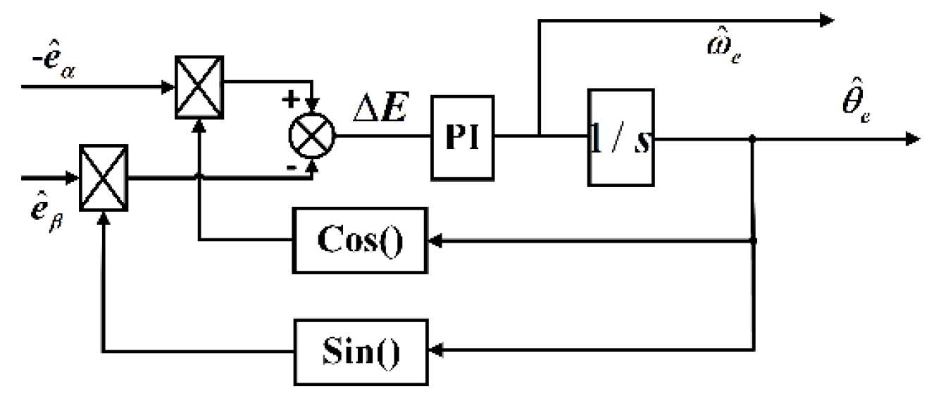
29]. To solve this problem, this section proposes a speed and position control technology based on a phase-locked loop (PLL), whose control framework is shown in
Figure 1.
According to
Figure 1, the following relationship can be obtained:
where,
is the coefficient of Counter-electromotive force;
is the phase angle of Counter-electromotive force, when
,
,Equation (20) can be simplified as:
In summary, the sensorless control block diagram of PMSM based on a new power converging law can be shown in the following
Figure 2.
In order to verify the effectiveness and practicability of the novel power sliding mode observer algorithm based on the phase-locked loop (NPSMO-PLL for short) scheme proposed in this paper, the control system block diagram of this sensorless control scheme is built, as shown in
Figure 2. In this control scheme, the speed loop and current loop are effectively improved and optimized using the sliding mode algorithm proposed in the literature [
30]. In terms of speed and position estimation strategy, the conventional position sensor control and sensorless control strategy can be selected through the on-off of the control line. The speed and position information obtained by the conventional position sensor is used as the reference value, and the speed information obtained by the sensorless control strategy is used as the observation value for comparison to verify the effectiveness of the sensorless control strategy.
5. Experimental testing
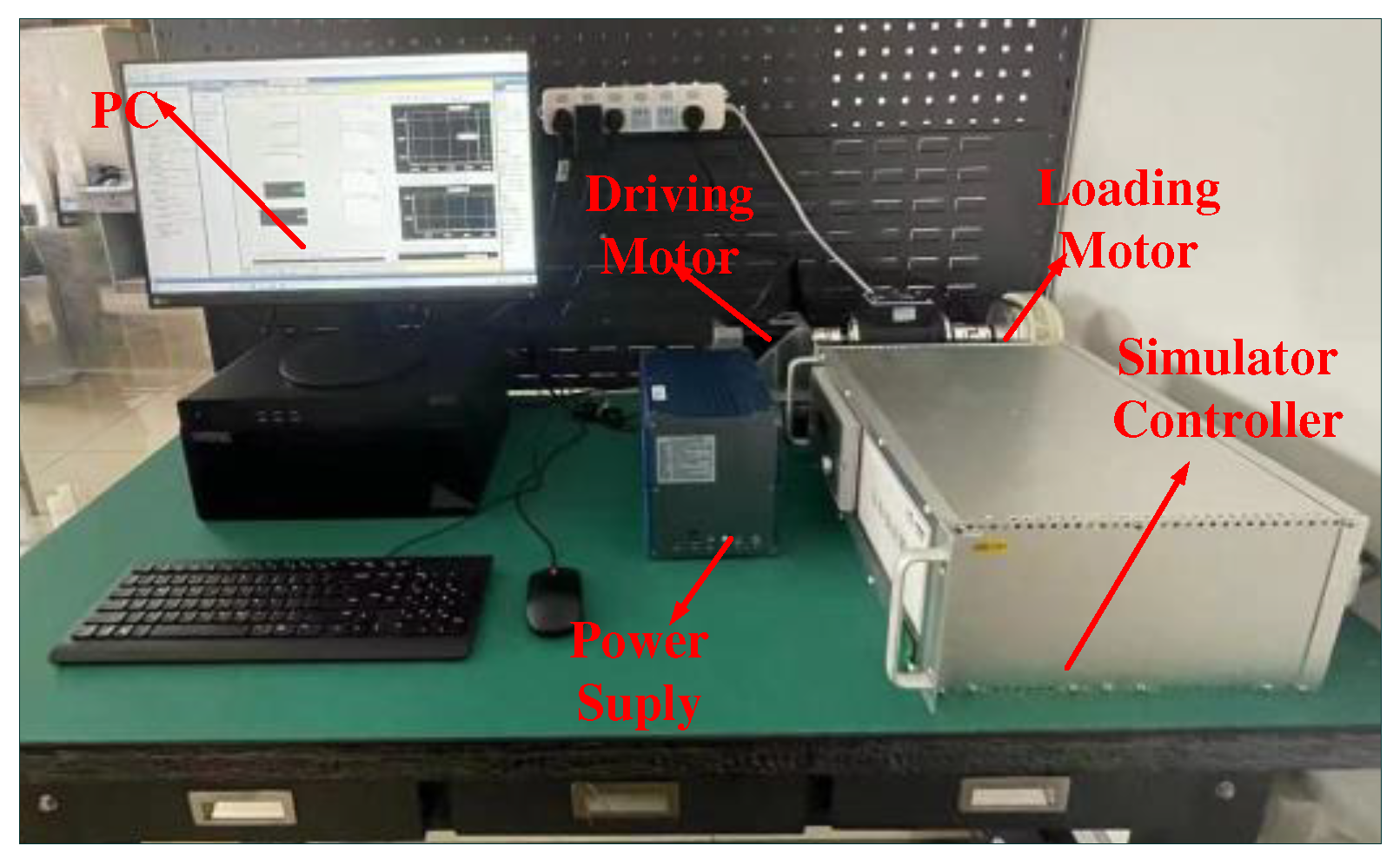
In order to further verify the simulation results of the control strategy proposed in this paper, the experimental platform of the motor system is built, and several experiments are implemented, which is shown in
Figure 3, and the parameters of the PMSM are shown in
Table 1.
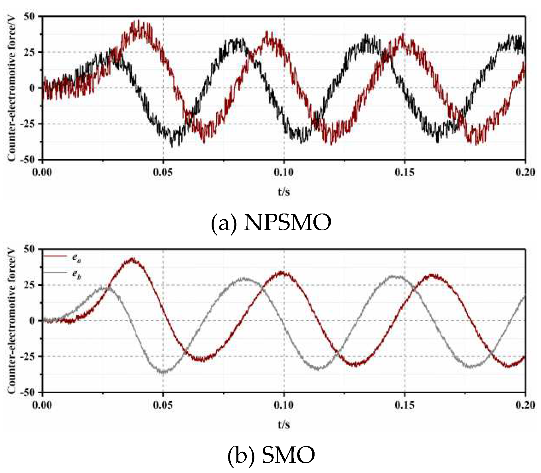
In order to verify the observation performance of the NPSMO proposed in this paper for counter-electromotive force, the NPSMO scheme proposed in this paper is compared with the conventional SMO scheme. As presented in
Figure 4a,b, since the proposed NPSMO can effectively reduce the chattering value in sliding mode control, the estimated test curve of Counter-electromotive force sum is smoother than that of conventional SMO, and the counter-electromotive force fluctuation can be controlled within 2.5V.
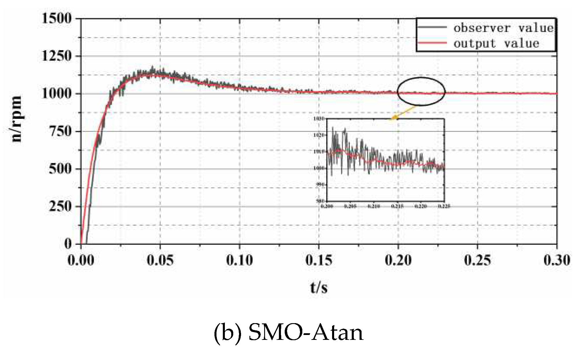
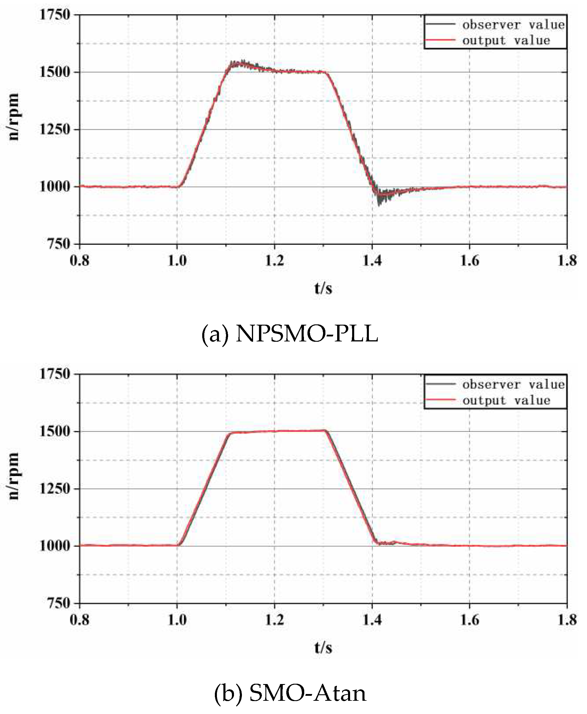
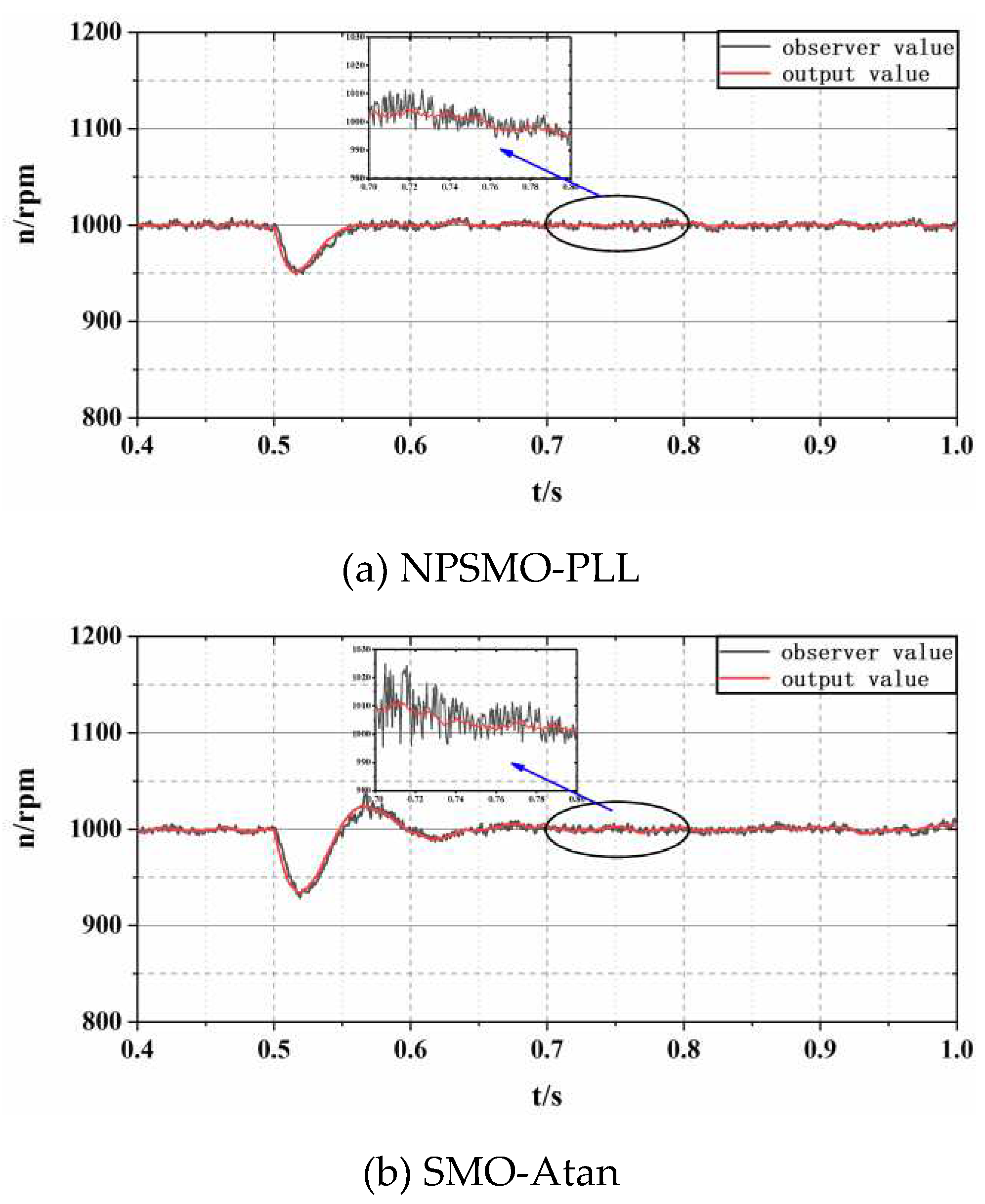
In order to verify the control accuracy of the proposed NPSMO-PLL, the proposed sensorless speed estimation strategy was compared with the conventional sensorless speed method based on the SMO-Atan controller to compare the PMSM speed performance under the two control strategies. The testing instructions are as follows:
Comparison of motor starting speed performance, with command speeds of 1000 r/min.
Comparison of motor acceleration and deceleration speed performance, with a command speed of 1000-1500r/min and a deceleration command of 1500-1000r/min
Comparison of motor loading performance, with a loading command of 10Nm
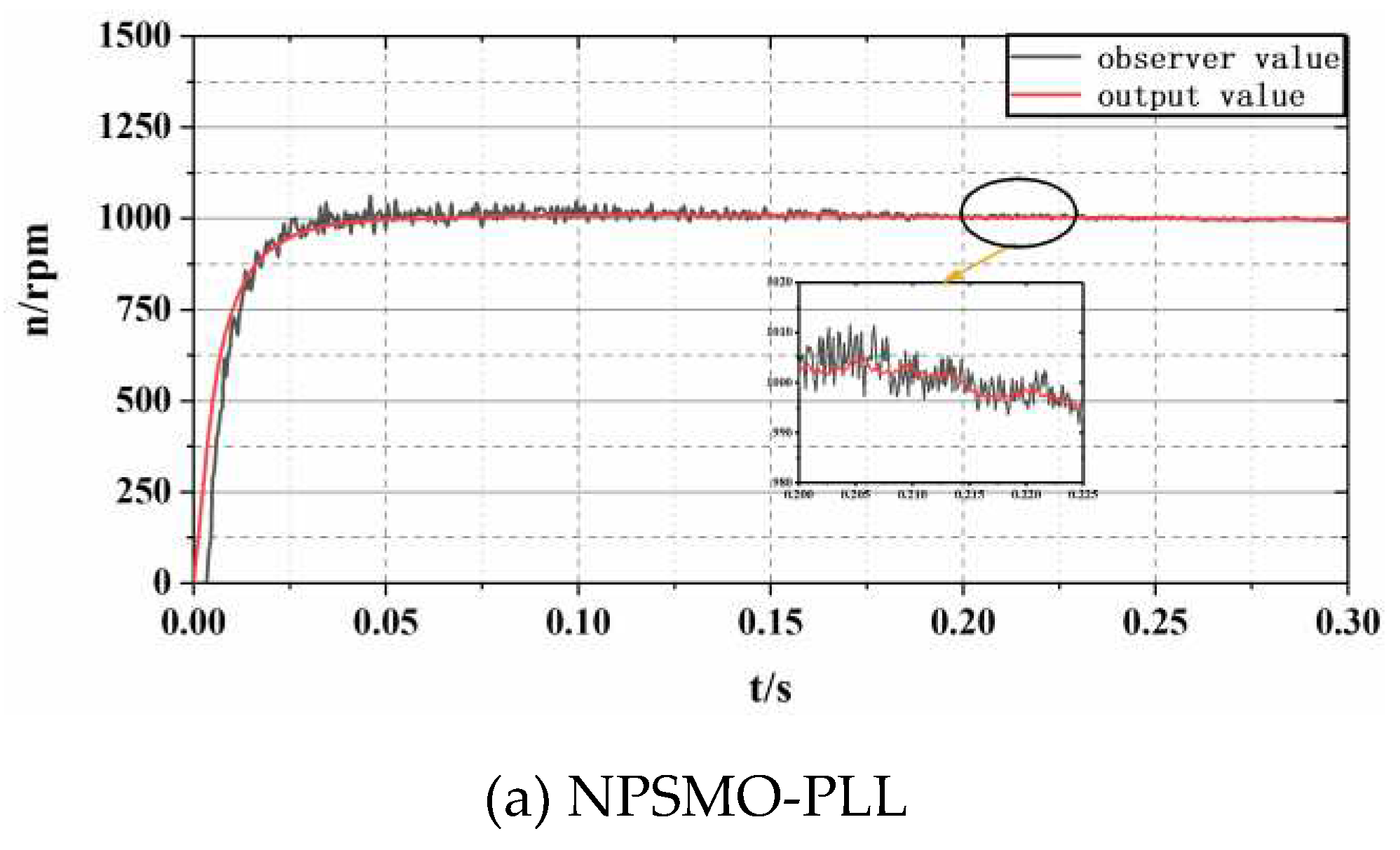
Figure 5 shows the start-up test of PMSM under two sensorless speed estimation strategies, NPSMO-PLL and SMO-Atan. As shown in
Figure 5a, the sensorless control technology based on NPSMO-PLL proposed in this paper can respond to the start-up command within 0.05s, and there is no overshoot during the start-up process. In addition, the tracking error can be controlled below 1% in the steady state; In
Figure 5b, The start-up time of conventional SMO-Atan sensorless control technology is more than three times that of NPSMO-PLL, and there is a large overshoot amplitude during the start-up process. The response speed and control stability of the control strategy proposed in this article have been validated through this experimental testing.
Figure 6 shows the speed testing of PMSM when receiving acceleration and deceleration commands. The experimental curve based on NPSMO-PLL control technology shown in
Figure 6a is very smooth, with no overshoot during acceleration and deceleration, and can complete the acceleration command response within 0.1 seconds. The sensorless speed control strategy based on SMO-Atan shown in
Figure 6b exhibits significant overshoot during acceleration, with fluctuations exceeding 30 r/min. When the acceleration command value is reached, the maximum steady-state error exceeds 10 r/min.
In order to verify the anti-interference ability of PMSM under the NPSMO-PLL control strategy proposed in this paper, a 10Nm loading testing was conducted and compared with conventional SMO-Atan control technology. From
Figure 7b, it can be seen that PMSM can complete loading response adjustment within 0.06 seconds under the sensorless control of NPSMO-PLL. The speed of the observed and output values can be controlled within 5%, and the anti-interference performance is ideal. The SMO-Atan control strategy shown in
Figure 7a has a regulation time which is more than three times that of NPSMO-PLL under loading disturbance conditions, and the maximum speed fluctuation during the regulation process exceeds 8%. From this loading experimental testing, the anti-interference ability and dynamic performance of the NPSMO-PLL sensorless control proposed in this article have been demonstrated.
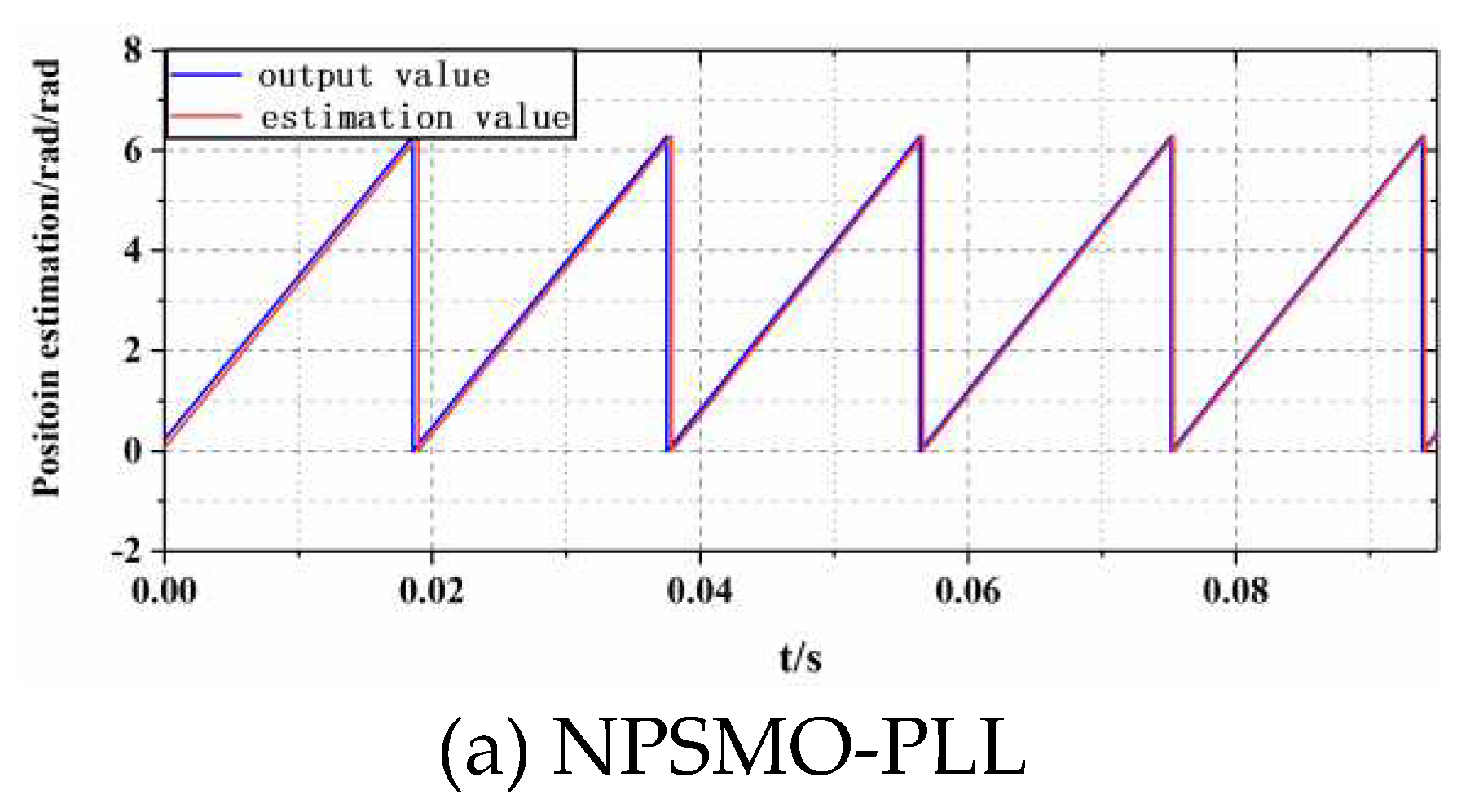
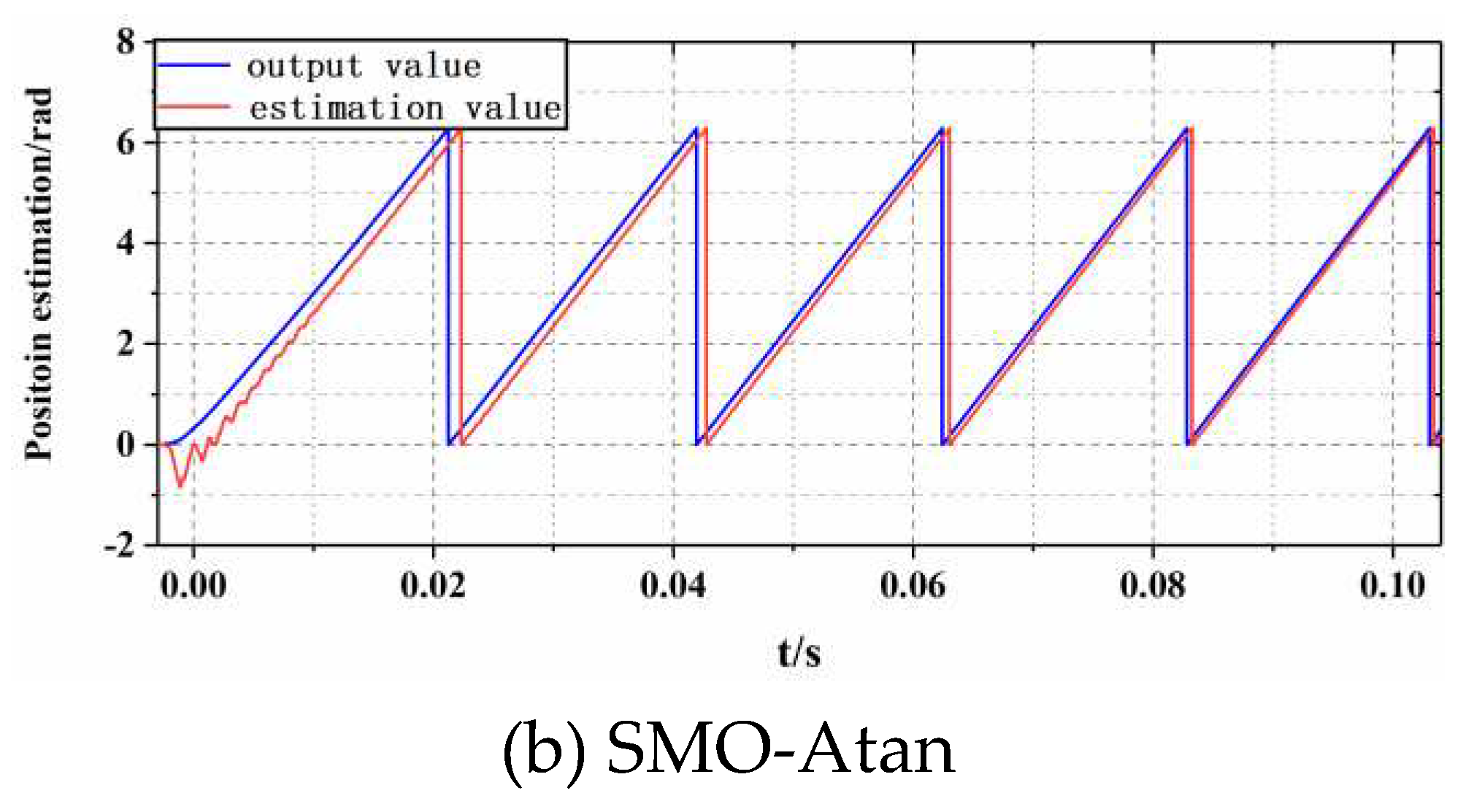
In order to verify the performance of position estimation based on the NPSMO-PLL scheme, rotor position estimation testing was conducted at a command speed of 1000 r/min, where the actual output value of the rotor position was detected through a 2500-line photoelectric encoder.
Figure 8a,b show the position estimation results of the motor test platform under two control strategies under the command speed.
Comparing the position estimation curves of PMSM under different control strategies shown in
Figure 8, it can be concluded that the position tracking performance based on the NPSMO-PLL sensorless control strategy proposed in this paper is ideal, and the error can be controlled within 0.21rad; The sensorless control strategy based on SMO-Atan has a tracking error of over 0.4rad during position estimation, and the amplitude fluctuation at steady-state exceeds 10%.
Through verifying the PMSM experimental results based on NPSMO-PLL sensorless control technology proposed in this article, the following characteristics can be verified:
It has an ideal observation effect for counter-electromotive force and can effectively improve estimation accuracy.
The start-up response speed is fast and there is no overshoot value during the process.
The acceleration/deceleration response is fast, and the speed is relatively stable after reaching the speed control command.
It has robust anti-interference ability and ideal speed adjustment when subjected to loading.
6. Conclusion
This article designs a sliding mode observer based on power converging law to observe the counter-electromotive electromotive force in PMSM where sensor installation is difficult. The PLL rotor position strategy is used to optimize the estimation of rotor position and speed. The experimental results of Matlab/Simulink and motor speed control platform prove that the sensorless control strategy based on NPSMO-PLL designed in this article is effective, the control current and counter-electromotive force in PMSM can be estimated with high accuracy. At the same time, through experimental tests on start-up, acceleration and deceleration, loading working conditions, it has been proven that the sensorless control technology proposed in this article has ideal control accuracy and anti-interference ability, which can ensure motor safety and stability in difficult sensor installation situation.
References
- Sun X, Wu C, Wang J.: Adaptive Compensation Flux Observer of Permanent Magnet Synchronous Motors at Low Carrier Ratio. IEEE Transactions on Energy Conversion. 36(4), 2747-2760, (2021).
- Alfehaid A, Strangas E, Khalil H.: Speed Control of Permanent Magnet Synchronous Motor with Uncertain Parameters and Unknown Disturbance. IEEE Transactions on Control Systems Technology. 29(6), 2639-2646, (2021).
- Fang S, Liu H, Wang H T, et al.: High Power Density Permanent Magnet Synchronous Motor with Lightweight Structure and High-Performance Soft Magnetic Alloy Core. IEEE Transactions on Applied Superconductivity. 29(2), 1-5, (2019).
- Wu G, Huang S, Wu Q, et al.: Robust Predictive Torque Control of N*3-phase PMSM for High Power Traction Application. IEEE Transactions on Power Electronics. 35(10), 10799-10809, (2020).
- Nair S V, Hatua K, et al.: Quick and seamless transition method for I-f to sensorless vector control changeover and on-the-fly start of PMSM drives. IET Electric Power Applications.14(2), 2231 - 2242, (2020).
- Sahebjam M, Sharifian M, Feyzi M, et al.: Novel methodology for direct speed control of a permanent magnet synchronous motor with sensorless operation. IET Electric Power Applications. 15(6), 728 – 741, (2021).
- Toso F, Davide D, Alotto P, et al.: A Moving Horizon Estimator for the Speed and Rotor Position of a Sensorless PMSM Drive. IEEE Transactions on Power Electronics. 34(1), 580-587, (2019).
- Gong C, Hu Y, Gao J, et al.: An Improved Delay-Suppressed Sliding Mode Observer for Sensorless Vector-Controlled PMSM. IEEE Transactions on Industrial Electronics. 67(7), 5913-5923, (2020).
- Luo X, Zhu L, Feng H, et al.: A high-speed Luenberger state observer for the sensorless speed control of a PMSM. IEEE Transactions on Industrial Electronics. 58(9), 4069-4077, (2015).
- Nair S V, Hatua K, Prasad N, et al.: Quick and seamless transition method for I-f to sensorless vector control changeover and on-the-fly start of PMSM drives. IET Electric Power Applications. 14(11), 2231-2242, (2020).
- Xu Z, Zhang T, Bao Y, et al.: A Nonlinear Extended State Observer for Rotor Position and Speed Estimation for Sensorless IPMSM Drives. Trends in Ecology & Evolution. 35(1), 733-743, (2020).
- Ge Y, Yang L, Ma X.: Sensorless control of PMSM using generalized extended state observer and adaptive resistance estimation. IET Electric Power Applications, 14(11), 2062-2073, (2020).
- Chen B, Shen A, Li P, et al.: Restart strategy for sensorless PMSM drive system based on zero-voltage vector. IET Electric Power Applications, 14(2), 2362-2369, (2020).
- Eull M, Preindl M. An Optimization-Based Reduced Sensor Virtual Flux Observer for PM Synchronous Machines. IEEE Transactions on Industrial Electronics, 68(5), 4320-4330, (2021).
- Mohamed, Lamine, Masmoudi, et al.: Amplification of Single Mechanical Fault Signatures Using Full Adaptive PMSM Observer, 64(1), 615-623, (2017).
- Teng Q, Bai J, Zhu J, et al.: Current sensorless model predictive torque control based on adaptive backstepping observer for PMSM drives. 13(1),187-202, (2014).
- Yang Z, Yan Z, Lu Y, et al.: Double DOF Strategy for Continuous-Wave Pulse Generator Based on Extended Kalman Filter and Adaptive Linear Active Disturbance Rejection Control. IEEE Transactions on Power Electronics, 37(2), 1382-1393, (2022).
- Zhu G, Li L, Xue M, et al. A full-domain fluidic-thermal approach for a high-speed PMSM considering the bearing components. IET Electric Power Applications, 16(2), 169-177, (2022).
- Tsai M, Tseng C, Li N, et al.: Implementation of a DSP-based speed-sensorless adaptive control for permanent-magnet synchronous motor drives with uncertain parameters using linear matrix inequality Approach. IET electric power applications, 16(7), 789-804, (2022).
- Toso F, Carlet P, Preindl M, et al.: Active-Flux-Based Motion-Sensorless Control of PMSM Using Moving Horizon Estimator. IEEE International Symposium on Sensorless Control for Electrical Drives, Conference Paper, 78-83, (2018).
- Yin S, Gao H, Qiu J, et al. Descriptor reduced-order sliding mode observers design for switched systems with sensor and actuator faults. Automatica, 76, 282-292, (2017).
- Yuan Z, Tian Y, Yin Y, et al.: Trajectory Tracking Control of a Four Mecanum Wheeled Mobile Platform: an Extended State Observer-Based Sliding Mode Approach, IET Control Theory and Applications, 14(3), 415-426, (2020).
- Zhang J, Tan C, Zheng G, et al.: On sliding mode observers for non-infinitely observable descriptor systems, Automatica, 147, 110676-1-110676-9, (2020).
- Liu Z, Zhu Q, Zhao L, et al.: A new result on observer-based sliding mode control design for a class of uncertain Ito stochastic delay systems, Journal of the Franklin Institute, 354(18), 8200-8216, (2017).
- Oussama S, Amor K, Moez A, et al.: A New Full-Order Sliding Mode Observer Based Rotor Speed and Stator Resistance Estimation for Sensorless Vector Controlled Pmsm Drives, Asian Journal of Control, 21(3), 1318-1327, (2019).
- Zhai J, Li S, Xu Z, et al. Reduced-Order Extended State Observer-Based Sliding Mode Control for All-Clamped Plate Using an Inertial Actuator. Energies, 15(5), 1780-1792, (2022).
- Xuejian C, Bo P, Ling L, et al.: A Novel Nonsingular Terminal Sliding Mode Observer for Sensorless Control of Permanent Magnet Synchronous Motor. Journal of Xian Jiaotong University, 50, 85-91+99, (2016).
- Gao W, Zhang G, Hang M, et al. Sensorless Control Strategy of a Permanent Magnet Synchronous Motor Based on an Improved Sliding Mode Observer. World Electric Vehicle Journal, 12(2), 74-92, (2021).
- Yu W, Jiang D, Wang J, et al.: Rotor-current-based fault detection for doubly-fed induction generator using new sliding mode observer. Transactions of the Institute of Measurement and Control. 42(1), 3110-3122, (2020).
- Bonache-Samaniego R, Olalla C and Martínez-Salamero L.: Dynamic Modeling and Control of Self-Oscillating Parallel Resonant Converters Based on a Variable Structure Systems approach, IEEE Transactions on Power Electronics, 32(2), 1469-1480, (2017).
|
Disclaimer/Publisher’s Note: The statements, opinions and data contained in all publications are solely those of the individual author(s) and contributor(s) and not of MDPI and/or the editor(s). MDPI and/or the editor(s) disclaim responsibility for any injury to people or property resulting from any ideas, methods, instructions or products referred to in the content. |
© 2024 by the authors. Licensee MDPI, Basel, Switzerland. This article is an open access article distributed under the terms and conditions of the Creative Commons Attribution (CC BY) license (http://creativecommons.org/licenses/by/4.0/).
