1. Introduction
As the automotive industry continues to progress, the need for smooth vehicle ride and handling stability is increasing. Research on semi-active and active suspensions has become a popular area of interest. However, despite the many excellent semi-active suspension and active suspension schemes proposed [
1,
2,
3,
4], the past research on suspension systems composed of linear damping and nonlinear stiffness is no longer applicable to the various suspension types that are widely used today, such as magnetorheological suspensions [
5], air suspensions [
6], and hydro-pneumatic suspensions [
7].
Therefore, it is important to create a fractional-order nonlinear suspension system containing nonlinear stiffness and fractional-order damping and to optimize the parameters of the fractional-order damping coefficients of this system.
The primary problem facing the study of this type of suspension system is to transform the linear damping force in the suspension system into a fractional-order damping force. You, H [
8] et al. tuned the suspension stiffness and damping by introducing two tuning values, and at the same time introduced a fractional-order damping force to simulate the viscoelastic properties of the material. They used a particle swarm algorithm to optimize these two adjustment values and initially established a fractional-order passive suspension system containing two degrees of freedom. However, the elastic elements of this system still exhibit linear elastic forces and stiffness. On the other hand, Chang, YJ [
9], et al. investigated the active control of a fractional order nonlinear suspension system. They designed a linearization method for the feedback of the suspension system based on the differential geometry method and obtained the optimal control rate through LQR control, which led to the optimization of the damping performance of the suspension system. However, the study only used simulation to verify the control effect. Therefore, to verify the optimization degree of the fractional-order nonlinear suspension model more comprehensively, this paper constructs a fractional-order nonlinear oil-air suspension isometric test bed. The optimization effect of the model is verified by comparing the simulation and experimental results.
In addition to the in-depth study of suspension system modeling, actuator structures, and control algorithms have become the core topics of interest in the field of active suspension. Currently, the widely adopted active suspension actuator structures include rotary motor type, linear motor type [
10], and electric oil and gas type [
11]. Among them, the rotary motor actuator covers different forms such as rack and pinion [
12], crank linkage [
13], and ball screw [
14]. The electric oil and gas actuator designed in this paper is structurally similar to the electrostatic actuator. The electrostatic actuator is mainly composed of two parts: the mechanical module (including hydraulic cylinders, hydraulic pumps, and coil springs) and the electrical module (including power supply, controller, DC motor, and the corresponding signal detection device). The electric oil and gas actuator, on the other hand, transforms the hydraulic cylinder and hydraulic pump in the mechanical structure into an oil and gas damper with adjustable damping, and the rest of the structure remains similar. As we all know, compared with the hydraulic damper, the oil and gas damper is equipped with an air chamber at the bottom, which can skillfully use air pressure to alleviate the vibration, and thus theoretically has a more excellent damping effect. In the electric module, the algorithm used for DC motor control has been improved and shifted from the common PID control algorithm to the fractional order PID control algorithm, which was proposed by Podlubny [
15]. Two additional control parameters
λ and
μ were introduced in the fractional order PID controller, where
λ denotes the fractional order of the integral link I in the fractional order PID control, and
μ denotes the fractional order of the differential link D in the fractional order PID control. This improvement allows for a wider and finer tuning range of the controller parameters, thus allowing for a more accurate determination of the strength of the proportional, integral, and differential links. This further improves the motor response speed and control accuracy, resulting in a more rapid and accurate damping adjustment of the oil and gas actuator.
In summary, this paper presents an electric hydrocarbon active suspension with fractional-order PID position control and describes a fractional-order nonlinear model of this suspension system. The accuracy of the simulation model of the fractional-order nonlinear suspension system, the feasibility of the designed actuator structure, and the excellent performance of the adopted fractional-order PID control algorithm are verified by comparing the simulation and experimental results.
2. Principle and Modeling
2.1. Electric oil-pneumatic active suspension working principle
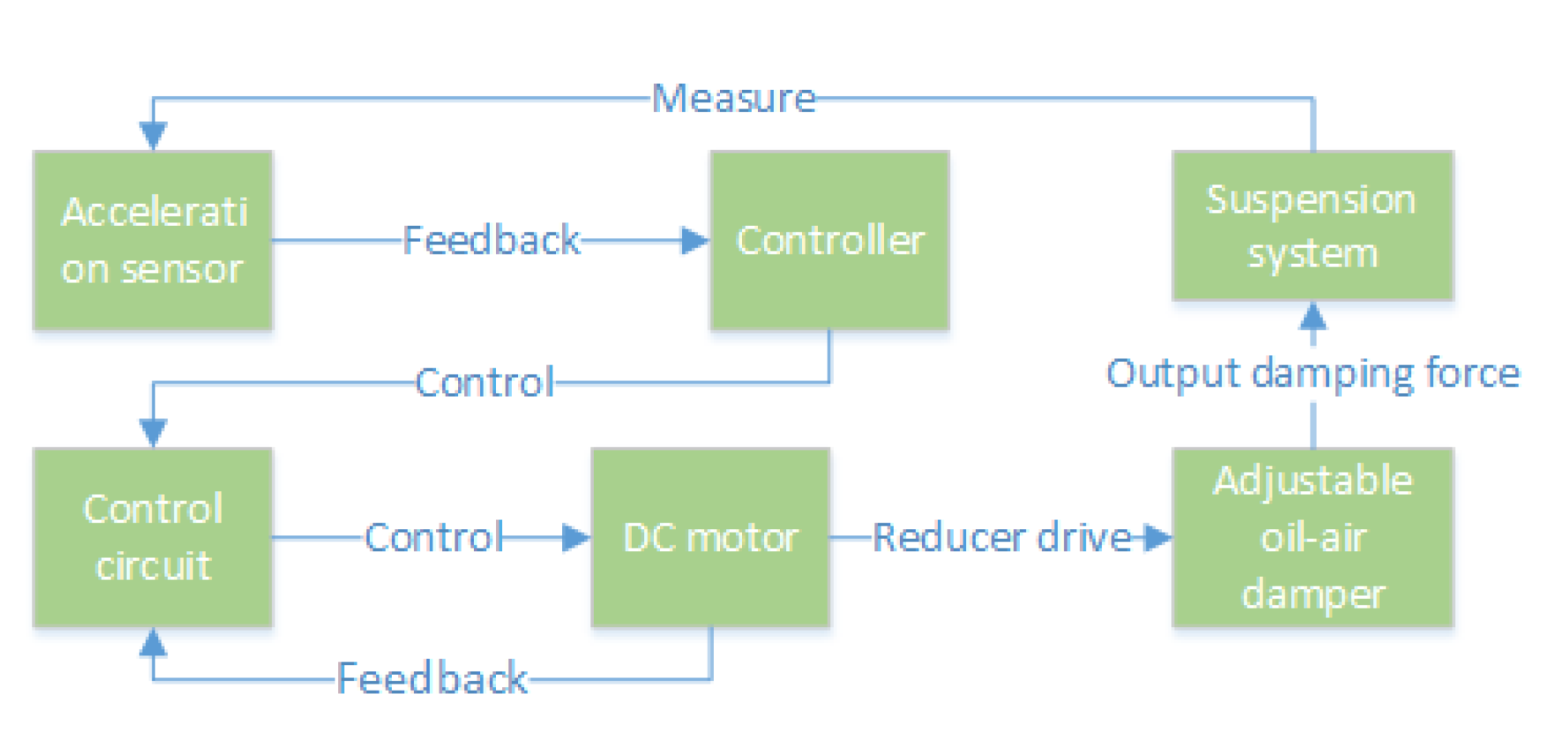
The design of the electric oil-air active suspension used in this paper is mainly based on an oil-air damper with adjustable damping. The suspension system measures the acceleration of the vehicle through acceleration sensors and feeds the signal back to the controller. The controller manipulates the rotation angle of the DC motor through a control circuit, which in turn realizes the damping adjustment of the damper through a gearbox transmission. This process allows the actuator to output adjustable damping force, thus realizing active control of the suspension system. The workflow of the hydro-pneumatic active suspension is shown in
Figure 1.
2.2. Fractional order damping force model for the electric oil-pneumatic actuator
Since the characteristics of electric oil and gas actuators are affected by a variety of factors, including conditions such as excitation frequency, external temperature, and usage history, this is consistent with the mechanical properties of viscoelastic materials. And since viscoelastic materials have both viscous and elastic properties, it is more accurate and reasonable to use a fractional order calculus model [
16] describing viscoelastic materials to depict the mechanical properties of the oil and gas damper. And the fractional-order damped Duffing system model [
17] describing the viscoelastic characteristics of the material is referenced in the design of the oil and gas suspension model. The fractional-order damping force at the output of the actuator can be calculated by the following equation.
where
is the spring-loaded mass displacement,
is the unsprung mass displacement,
p is the order of the fractional order differential term, and
is the fractional order viscoelastic damping coefficient of the suspension system.
is the fractional order calculus operator, and the three main definitions of fractional order calculus used so far are the Riesmann-liouville formula, Grunwald-Letnikov formula, and Caputo formula. In this paper, the Grunwald-Letnikov formula [
18] is used to define the fractional order calculus operator, and its differential definition is shown in the following equation.
where means taking the nearest integer to , is the coefficient of the binomial; the definition of the integral only requires changing the fractional order p in the differential equation (2) to -p.
Since the damping of the oil-pneumatic actuator used is adjustable, the fractional order viscoelastic damping coefficient
and the actuator damping force
are calculated as shown in equations (3) and (4).
where
b is the damping scale of adjustable dampers, 10≥
b≥1;
c is the damping coefficient of the passive suspension.
2.3. Suspension system modeling
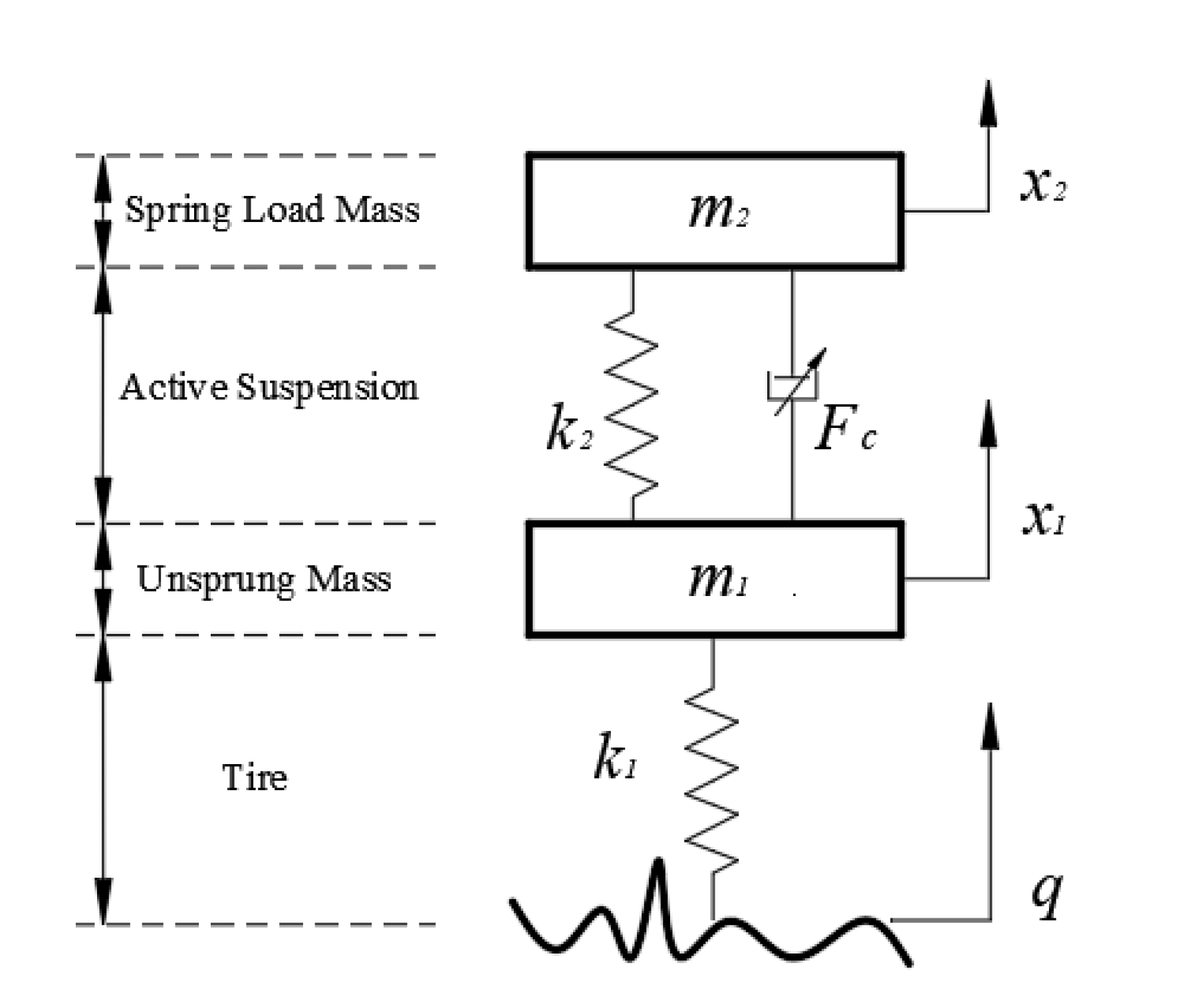
In this paper, a fractional-order nonlinear suspension system model is constructed mainly based on the viscoelastic properties of the employed adjustable-damped oil-air actuator. The constructed active model of the 1/4 vehicle suspension system is shown in
Figure 2 below. In this figure,
denotes the elastic force output from the nonlinear elastic element,
represents the spring load mass,
represents the unsprung load mass,
is the tire stiffness, and
q represents the road excitation.
The equation for the nonlinear elastic force
in the figure is shown in the following equation.
where is the linear stiffness of the elastic element and e is the nonlinear coefficient of the elastic element.
From
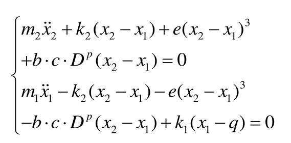
Figure 2 combined with equation (5), the differential equation of motion of the suspension system can be obtained as:
In the study of the 1/4 suspension system, the conventional passive nonlinear suspension system model differential equation of motion is shown in the following equation.
2.4. Pavement excitation model
A filtered white noise pavement model was used to construct the pavement input excitation
q for the active control study process [
19], with the following principle formula.
Where is the reference spatial frequency; is the road surface unevenness coefficient; is the space under the cut-off frequency; is the vehicle speed of 50km/h. Since the amplitude range of the shaker in the experimental equipment is 0-0.01m, is taken as 0.04 unit intensity of Gaussian white noise.
In this paper, regarding the parameters of the international standard ISO 8608 [
20] for A, B, and C pavements, the three classes of pavements are combined to form the pavement excitation used in the study, and to consider only the effects caused by pavement unevenness, the pavement excitation formula is designed as shown in the following equation.
,
, and
are the geometric means of pavement unevenness coefficients for A, B, and C-class pavements, respectively. The pavement excitation images are shown in
Figure 3 below.
2.5. Electric oil-pneumatic actuator model
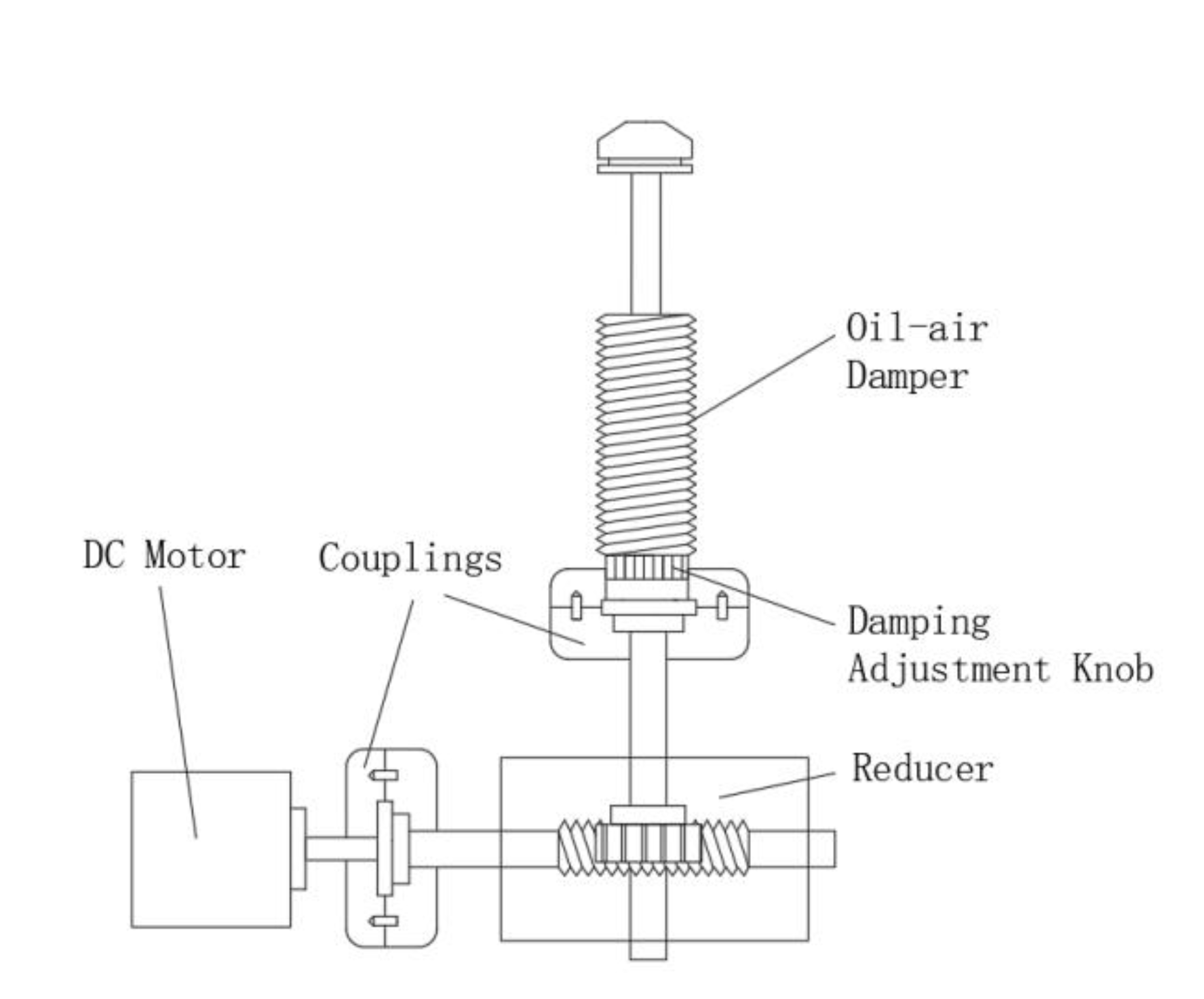
The oil and gas-electric actuator mainly consists of a DC motor, a worm gear reducer, and an oil and gas damper with adjustable damping. The reasons for connecting the worm gear reducer to the DC motor and the oil and gas damper are as follows:
1)Improvement of motor position control accuracy: Due to the small rotation angle of the motor shaft, its position control accuracy is relatively low. In addition, dampers usually require a smaller adjustment range. Therefore, installing a gear reducer helps to ensure high accuracy of motor position control.
2)Increased torque: In an isometric drive, the output torque of the motor may not be sufficient to drive the rotation of the damper adjustment knob. By installing a gear reducer, the output torque can be effectively increased to ensure proper operation of the damper.
3)Reduced Space Occupancy: The turbine worm gear reducer is smaller in size compared to the gear reducer, which helps to reduce the space occupied by the actuator and improve the compactness of the overall system.
The simple mechanical structure of an electric oil and gas actuator is shown in
Figure 4.
Known worm gear reducer reduction ratio
i, when the motor angle position is 0 (motor shaft rotation 0 rad), the scale parameter
b=1 in equation (2). When the motor angular position reaches the maximum value of damping adjustment (when the motor shaft rotates 2π/
i rad), the scale parameter
b=10, from which the relationship between the motor shaft rotation angle
and the parameter
b can be obtained as shown in the following equation.
The relationship between the output damping force of the damper and the rotation angle of the motor shaft can be obtained by combining (4) and (10):
The above equation can be used to control the output damping force of the actuator by controlling the angle of rotation of the motor.
2.6. DC motor mathematical model
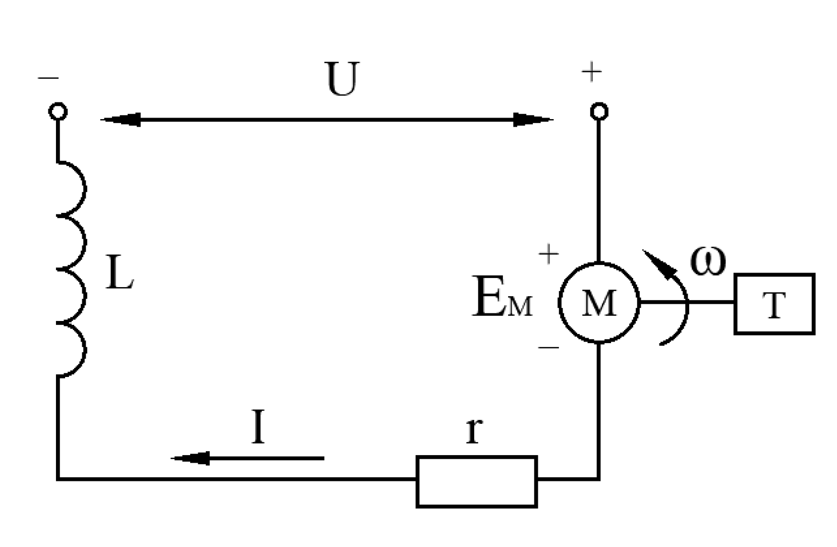
The equivalent circuit diagram of the DC motor is shown in
Figure 5 below. In the figure,
U represents the supply voltage,
L is the motor inductance,
I is the armature circuit current,
r is the motor internal resistance,
is the motor-induced electric potential,
ω is the motor shaft rotation angular velocity, and
T is the motor output torque.
From
Figure 5 above, the motor voltage balance equation can be obtained as shown in the following equation.
where
t is the time.
The equations of induction potential, electromagnetic torque, and torque balance of a DC motor are known as shown in equations (13), (14), and (15), respectively.
Where
is the counter-electromotive force constant,
is the torque constant,
J is the total rotational inertia of the working mechanical system converted to the motor shaft, and
is the load torque. It is known that the angular velocity of motor shaft rotation
ω=d
θ/d
t, and the mathematical model equation of the DC motor can be obtained from the above equation (12), (13), (14), and (15).
The Laplace transform of the above equation (16), due to the effect of the reducer, the load torque of the motor is very small and can be neglected here, and the result of the transformation is shown in the following equation.
From the above equation, the transfer function
H(
s) of the DC motor turning angle
and the motor voltage
U is given by the following equation.
3. Principle of active control of suspension system
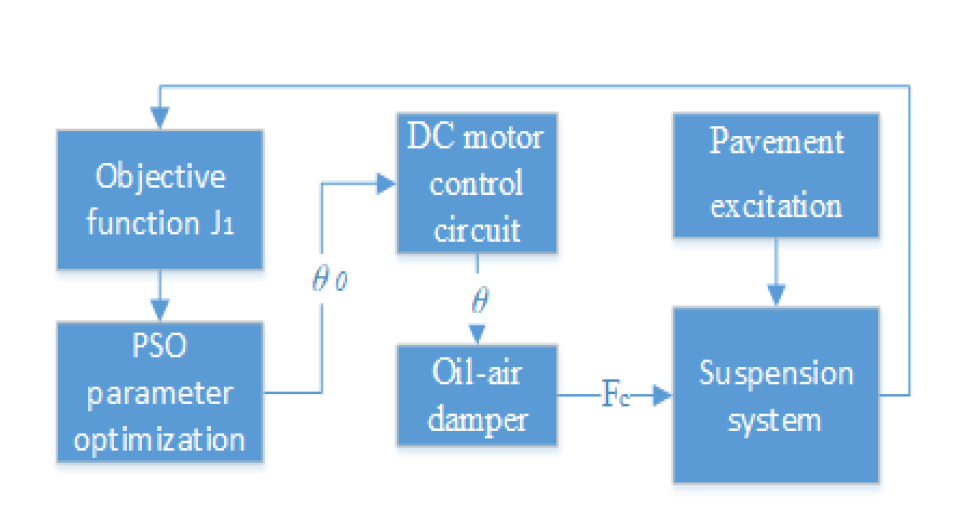
In this study, the objective function of the suspension system is optimized by using the particle swarm algorithm so that the controller outputs the ideal rotation angle parameter of the motor, and the control principle is schematically shown in
Figure 6. The particle swarm algorithm is used to optimize the simple harmonic excitation objective function
with different frequencies and amplitudes to derive the parameter of the ideal rotation angle
. The DC motor control circuit outputs the actual rotation angle
θ according to the ideal rotation angle
, and the oil-air damper adjusts the damping according to the actual rotation angle output by the motor, to realize the output of the damping force
to achieve a superior suspension control effect. In
Figure 6, the working principle of the DC motor control circuit is mainly demonstrated in
Figure 7. The current DC motor rotation angle
θ forms a deviation value
from the given rotation angle
, and the output power supply voltage
U is controlled by the fractional-order PID control algorithm, thus realizing the precise control of the DC motor rotation angle.
3.1. Fractional order PID controller simulation design
The transfer function of the fractional order PID controller is shown in the following equation.
In this paper, a modified oustaloup filter [
21] is used to implement the approximation of the fractional order calculus operator
. The main steps in constructing the fractional order calculus operator are as follows:
1)Determine the filter order N and the approximate frequency band [, ].
2)Calculate the zero pole
and
, which is calculated as shown in equations (20) and (21).
3)Finally, the approximation to the fractional order calculus operator is completed, as shown in equation (22).
The above equation α must be satisfied (0<α<1). In general, the approximate frequency band is set as [0.001,1000], the filter order N is 5, and the weighting parameters are selected as b=10, d=9 to meet the accuracy requirements. The improved oustaloup filter for and that approximates the fractional order calculus operator is designed from equation (35) above.
3.2. Numerical implementation of fractional order PID controller
The FOPID controller in the experimental control circuit needs to be designed using a discretized fractional order PID formulation, and in this paper, we use the
formulation, whose differential definition is shown in equation (2). The control law of fractional order PID is shown in the following equation [
22,
23,
24].
where

and

are fractional order calculus operators, where
λ and
μ must be real numbers,
t is the independent variable, and
is the lower bound of the variable, where the independent variable
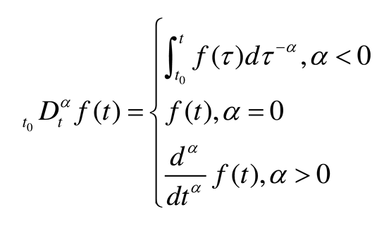
t is time. The uniform fractional order calculus operator

is defined as:
where
α is the fractional order.
The conjunction (2), (23) gives:
where
and
are the integral term coefficients and differential term coefficients, respectively. The fractional order calculus equation is generally implemented by numerical approximation. The two coefficients can be approximated by using the following recursive equations.
When the calculation step h chosen in the above equation is small enough, the limit finding operation in the above equation can be ignored, and
=0 in this paper, the following equation is obtained.
From the above equation, the discretization equation for fractional order PID can be obtained as follows.
To describe the fractional order PID control circuit more clearly, the flow of fractional order PID position control is described in Algorithm 1.
|
Algorithm 1. Fractional order PID position control flow. |
| Fractional order PID position control algorithm |
Input: Control circuit controller parameters , , , λ, μ ideal angle of rotation .
Output: actual rotation angle θ. |
For (j=0; j<k; j++); do
Calculate the error between the target value and the actual value: .
Calculate the binomial coefficients and from equations (26), and (27).
From equation (29) calculate the voltage of the input motor U.
Error transfer: .
Return . |
3.3. Judgment condition of damping adjustment
In this paper, the pavement unevenness of the input pavement excitation is mainly used as the basis for judging the damping adjustment. The classification criteria of known pavement unevenness are shown in
Table 2.
According to the data in table 2, the judgment basis for designing the damping adjustment is shown in the following equation.
According to equation (30), the total damping coefficient of the suspension system is the optimal damping coefficient obtained by parameter search when the road surface unevenness is , which corresponds to level A of the road surface. For the road surface unevenness , the total damping coefficient of the suspension system is the best damping coefficient obtained by parameter optimization, which corresponds to level B of the road surface. In case of , the total damping coefficient is the best damping coefficient obtained by parameter optimization, which corresponds to the suspension system at level C. The damping coefficient is the best damping coefficient obtained by parameter optimization. This means that the damping coefficient can be flexibly adjusted according to changes in road leveling, enabling the suspension system to achieve better damping in all road conditions.
3.4.Objective function and constraints
Before determining the parameters to be searched, the objective function of the search and the constraints to be satisfied by the search results need to be specified. Suspension system performance is evaluated based on body acceleration, suspension dynamic deflection, and tire dynamic loads, which interact with each other. Body acceleration is used to evaluate ride smoothness, tire dynamic loads are used to evaluate handling stability, and suspension dynamic deflection measures the effect on body attitude. Therefore, when performing active suspension control, handling stability needs to be taken into account and the suspension dynamic deflection needs to be controlled within an acceptable range based on optimizing the vehicle ride smoothness. Therefore, the objective function
is constructed as shown below.
where the subscript p represents the passive suspension indicators and rms(.) denotes the root mean square value of each indicator. The purpose of this design is to dimensionlessize each performance index and facilitate the selection of weighting factors. are the weighting coefficients due to the different importance of each index in the suspension system. Let and determine the weighting coefficient of the required optimization indexes according to the required order of optimization of each index combined with the constraints. Since the permitted travel of the oil and gas damper is 0.04m in the equiproportional model used in the experiment, is taken in the constraint. When the output of the suspension system does not satisfy the constraint, the weighting coefficients and to be readjusted.
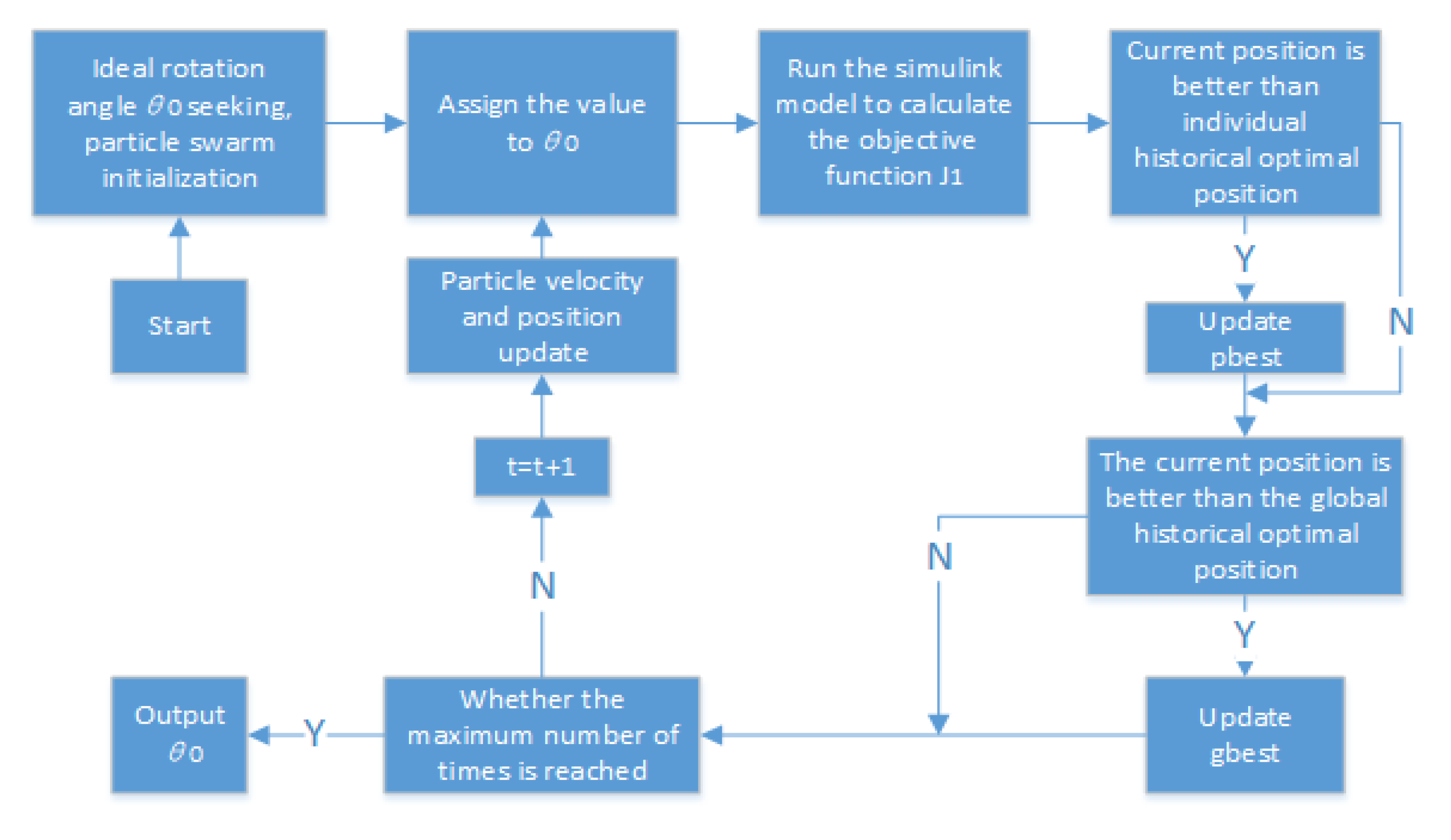
3.5.Parametric optimization principle and process
In this paper, the particle swarm algorithm [
25] is used to find the optimal objective function
and the goal is to find the optimal turning angle
, to achieve the optimal control of body acceleration and improve the smoothness of the vehicle. The principle of the particle swarm algorithm for finding the optimum is shown below:
The initial parameters of the particle swarm are set, including the inertia factor w, acceleration constants and , the number of particles in the swarm S, the maximum number of particle iterations T, the upper bound and the lower bound for the parameter search. The position information of particle m is ,…,. The particle search velocity is ,…,), n is the number of optimization-seeking parameters, i.e., the dimension of the solution space, and n=1 when the optimization is sought for the objective function . To prevent the particle velocity from being too large and exceeding the set boundary, the velocity of particle m is limited to , the part exceeding is taken as the boundary value.
t denotes the number of current iterations of the particle and the particle velocity update formula is shown in the following equations.
The particle position update formula is shown in the following equation.
Where denotes the particle m individual current optimal position parameter and denotes the particle swarm global current optimal position parameter. 、 denote the random number between [0,1].
The individual m optimal position update equation is:
The global optimal position update formula is:
When the objective function
is optimized, the upper bound
is set to [2π/
i] and the lower bound
is set to [0], because the maximum rotation angle of the adjustable damping knob is 2π. The rest of the initial parameters are shown in
Table 3. The algorithm optimization flow is shown in
Figure 8.
After preliminary simulations and experimental studies, combined with the actual parameters of the experimental rig, the values of each parameter can be obtained as shown in
Table 4 below.
Among them, the selection of the reduction ratio i of the reducer mainly considers the following factors:
As mentioned earlier, if the reduction ratio of the selected reducer is too large, the output torque may not be sufficient to push the damping adjustment knob, resulting in a decrease in control accuracy. Conversely, if the reduction ratio is too small, this will cause the time required for damping adjustment to increase to a given value, thereby slowing down the response of the system. Therefore, the reduction ratio i=1:20 is selected to balance the system performance, taking into account the control accuracy and output torque, while referring to the available reducer models on the market.
The simulation model of the suspension system is established according to the parameters in
Table 4, and then the objective function
and the ideal turning angle
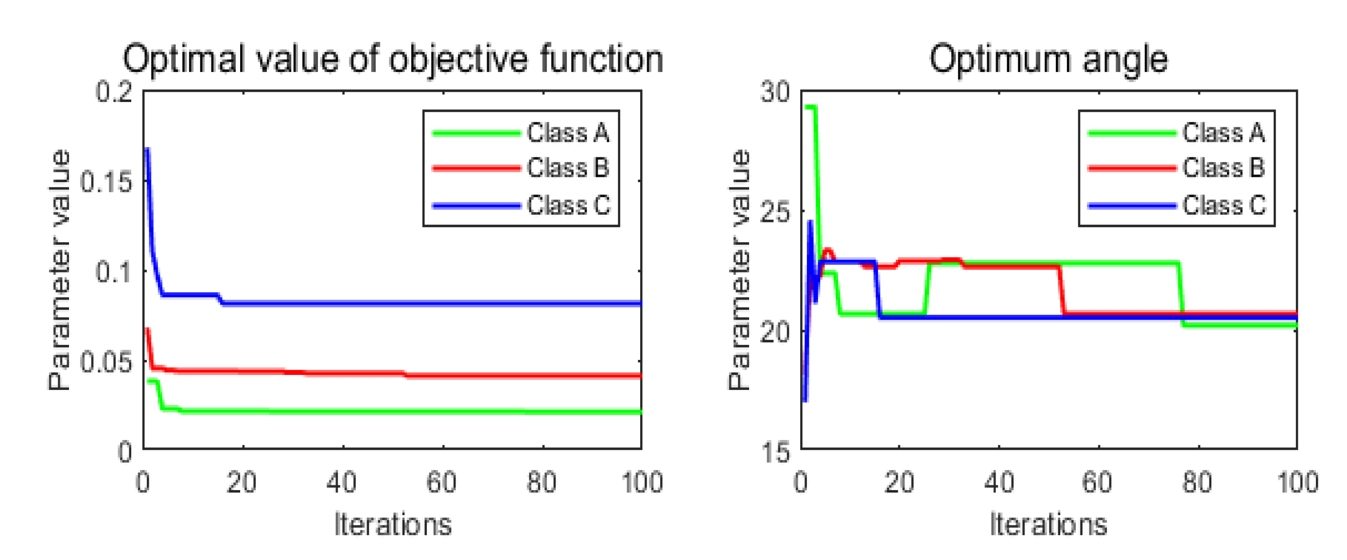
are searched for under each road level respectively, and the searched results are shown in
Figure 9 below.
From the
Figure 9, it can be seen that the optimal values of the objective function
gradually increase with the increase of the pavement grade, which are 0.0211, 0.0453 and 0.0813, respectively. while the optimal values of the ideal turning angle first increase and then decrease, which are 20.1804, 20.6578, and 20.5130 respectively.After determining the optimal value of the ideal angle, the optimal angle value obtained from the optimization search is used as the given value of the controller, and the PID algorithm and the fractional-order PID algorithm are used to control the motor angle respectively and the control principle is shown in Fig.7. After a large number of simulations and experimental trials, the controllerparameters are obtained as shown in
Table 5 below.
4. Simulation and experimental results study analysis
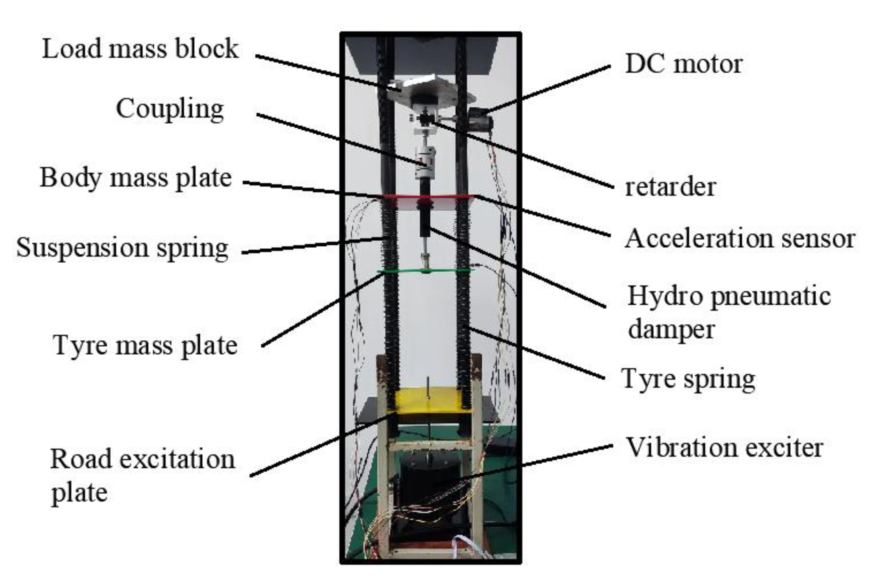
To verify the accuracy of the established fractional order nonlinear suspension system describing the oil-pneumatic suspension, the superiority of the fractional order PID controller compared with the PID controller, and the feasibility of the designed electric oil-pneumatic active suspension, simulations, and bench tests are performed for the equiproportional electric oil-pneumatic active suspension device shown in
Figure 10.
4.1. Study on the superiority of fractional order nonlinear passive suspension model
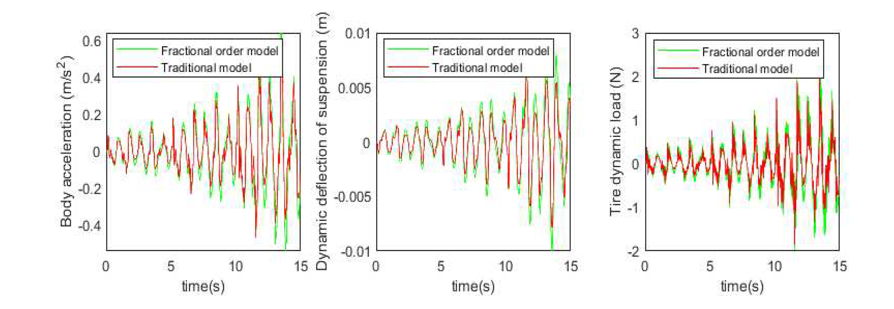
Before proceeding to the active suspension control study, the accuracy of the used fractional order nonlinear passive suspension model is demonstrated. At this point,
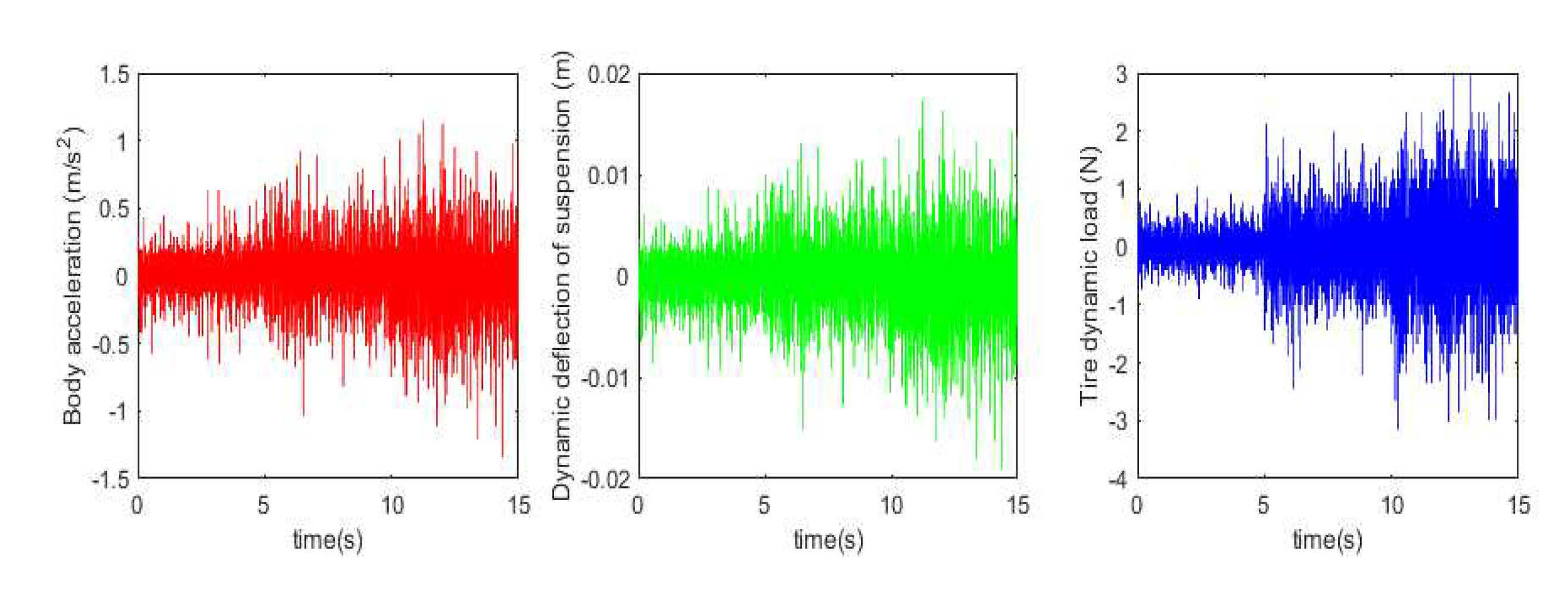
b=1, the body acceleration, suspension dynamic deflection, and tire dynamic load under simulation and test are obtained as shown in
Figure 11 and
Figure 12 below.
Based on the simulation and test results, the root mean square values of each suspension index were obtained as shown in
Table 6 below.
It can be observed from the data in the above figure and table that the simulation results of the fractional-order nonlinear suspension system model used in this paper are closer to the actual values compared to the conventional nonlinear suspension system model. Specifically, the accuracy of body acceleration is improved by 18.5%, the accuracy of suspension dynamic deflection is improved by 20%, and the accuracy of tire dynamic load is improved by 19.6%. It can be seen that the use of a fractional order nonlinear suspension system model to simulate the oil and gas suspension system can reflect the actual situation more accurately than the traditional nonlinear model.
4.2. Fractional order PID controller superiority verification
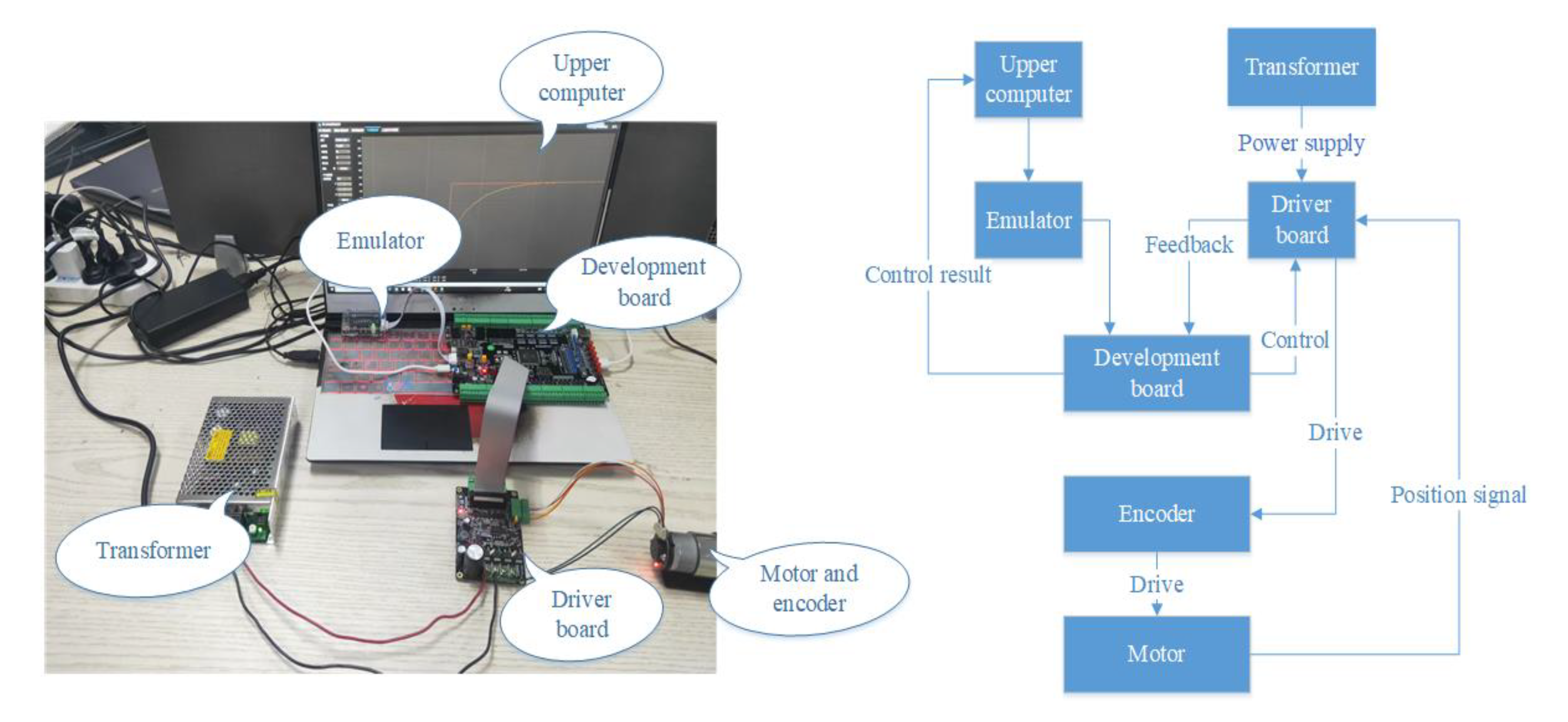
To optimize motor corner control, this paper introduces the fractional-order PID control algorithm to replace the traditional PID control algorithm and verifies the excellent performance of the fractional-order PID control algorithm in motor corner control through simulation and test results. In the actual implementation, this paper chooses the STM32-F407 development board as the carrier of the control algorithm and uses Keil software to write PID and fractional-order PID control programs in the upper computer and set the initial parameters of the controller. The control driver board is powered by a transformer, which drives the motor through an encoder. The Hall sensor on the driver board is responsible for acquiring the position signal of the motor and feeding it back to the development board. The development board then controls the angle of the motor in real-time and feeds the control results to the host computer for display
Figure 13 shows the information about the test equipment and the test flow.
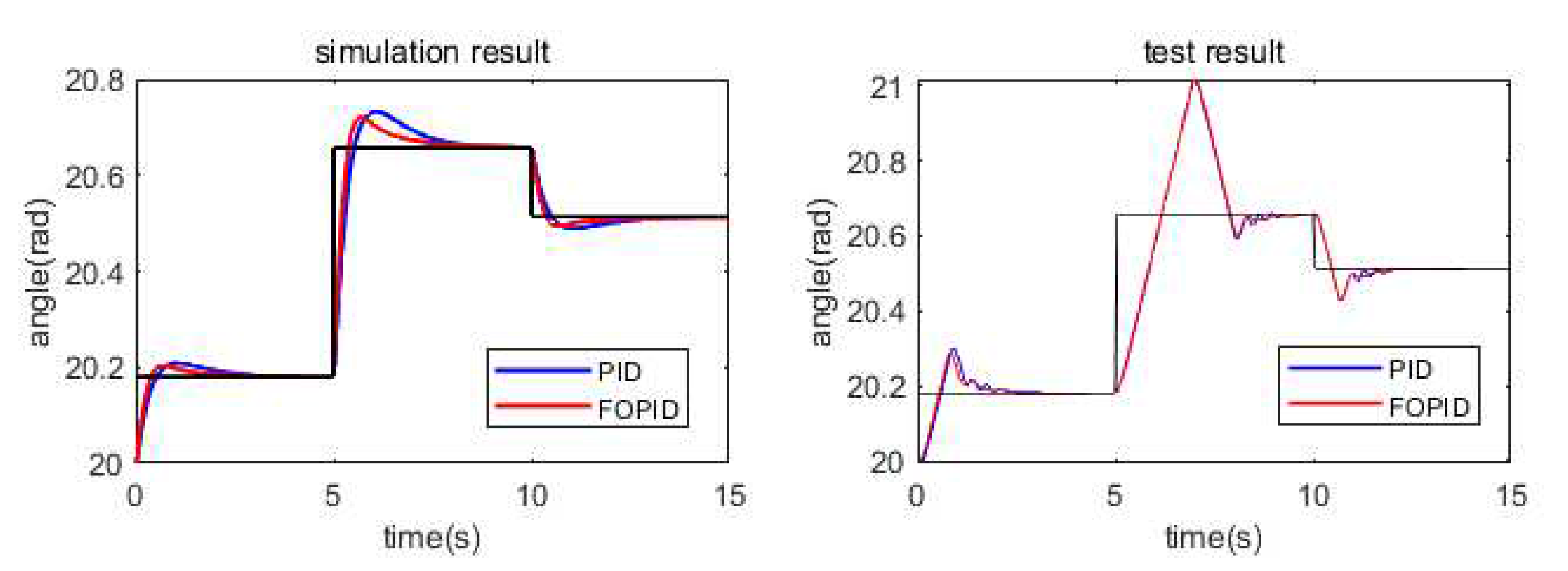
To avoid system instability caused by excessive overshoot, the initial rotation angle is set to 20 rad. The simulation and test results are shown in
Figure 14 below.
It can be observed from the simulation and experimental results that the fractional order PID controller shows more effective optimization in motor corner control compared to the conventional PID controller. In the simulation, the root mean square value of deviation under PID control is 0.2629, while the root mean square value of deviation under fractional-order PID control is 0.2563. In addition, the root mean square value of deviation under PID control is 0.1158, while the root mean square value of deviation under fractional-order PID control is 0.1147. This suggests that the use of fractional-orderPID controllers can improve the overall performance of the motor corner control while reducing the deviation. overall performance of the corner control.
4.3. Suspension active control results analysis
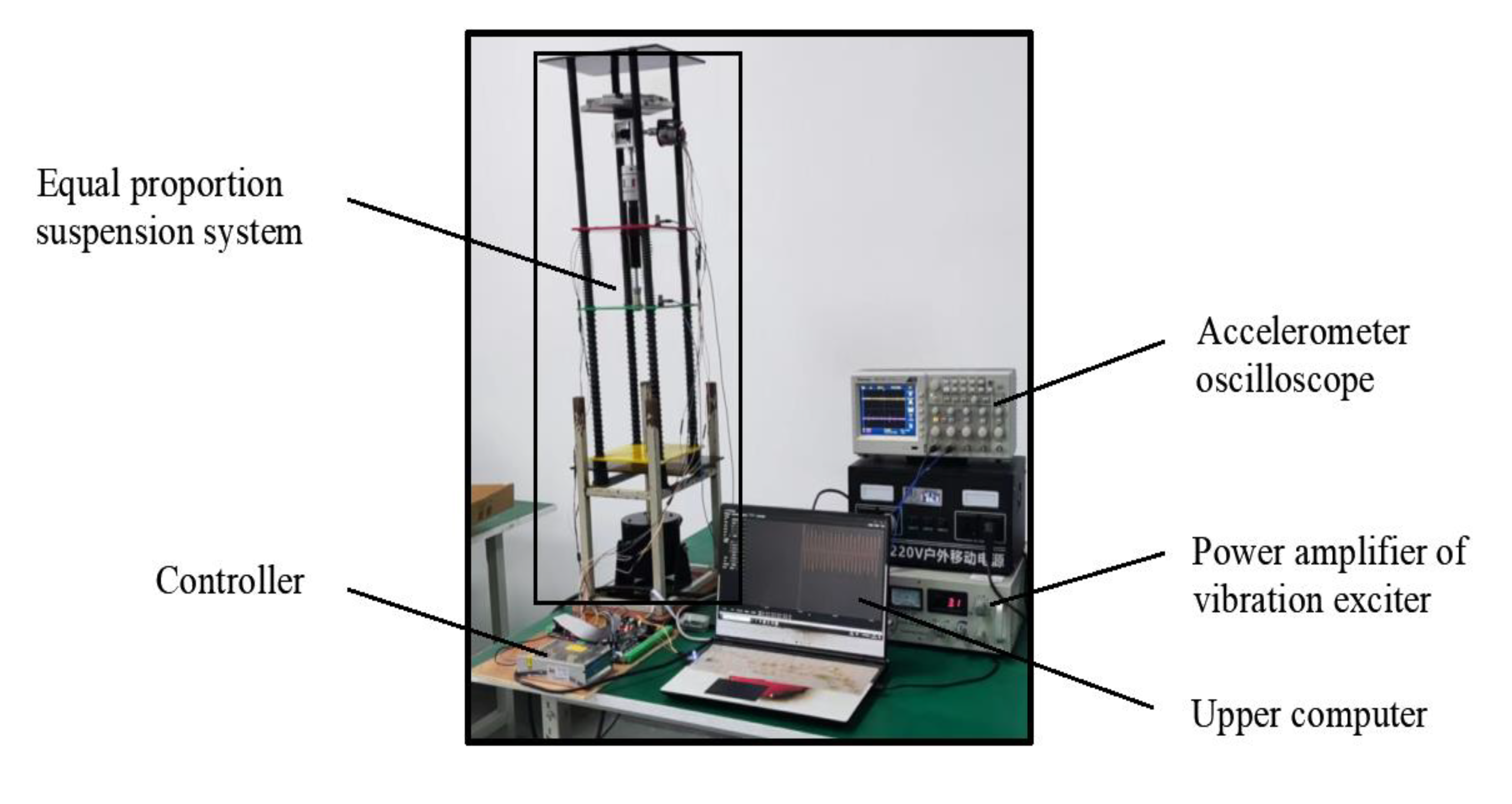
To verify the feasibility of the designed fractional-order PID position feedback control in an electric-hydrocarbon active suspension system, the body acceleration, suspensiondynamic deflection, and tire dynamic loads in the passive and active control states were simulated and experimentally investigated. The constructed test rig for the active suspension system is shown in
Figure 15 below. This study aims to evaluate the performance of fractional-order PID control in a real active suspension system to gain a more comprehensive understanding of its potential for improving vehicle dynamic characteristics.
Based on the simulation and test results, the root mean square values of each suspension index were obtained as shown in
Table 7 below.
According to the simulation results, compared with the passive suspension system, the electric oil-air active suspension achieves 75.2% optimization in body acceleration, 57.1% optimization in suspension dynamic deflection, and 75.6% improvement in tire dynamic load. The experimental validation shows that compared with the traditional passive oil-air suspension system, the designed electric oil-air active suspension can effectively improve the damping performance of the suspension system, which is theoretically feasible. The specific experimental results show that the body acceleration is increased by 89.8%, the suspension dynamic deflection is increased by 56.7%, and the tire dynamic load is increased by 73.4%. This indicates that the electric oil-pneumatic active suspension system has been significantly optimized in terms of body acceleration, suspension dynamic deflection, and tire dynamic load, which verifies the accuracy of the simulation conclusions and confirms the feasibility of the designed structure for engineering applications.
5. Conclusion
This study focuses on an electric-hydrocarbon active suspension under fractional-order PID position feedback control and constructs a fractional-order nonlinear system model describing this suspension type. We developed mathematical models for each mechanism and conducted a series of in-depth studies through MATLAB and Simulink simulations as well as bench experiments. The main contributions of the research include:
1)Using the particle swarm algorithm, the optimization of damping coefficients of the suspension system under different road surface grades is successfully achieved based on the road surface unevenness coefficient. This research provides an effective method to find the optimal damping coefficients.
2)Through the simulation and experiment of the fractional-order nonlinear oil-pneumatic suspension system, the data of body acceleration, suspension dynamic deflection, and tire dynamic deformation of the suspension system were obtained. This confirms that the fractional-order nonlinear oil-air suspension system is more suitable for describing the dynamic characteristics of oil-air suspensions than the conventional nonlinear system.
3)A digital implementation of a fractional-order PID control circuit for motor angle control is proposed. The superiority of the fractional order PID control circuit over the conventional PID control circuit is verified through simulation and experimentation of the actuator control circuit.
4)An actuator structure is designed to adjust the damping using a motor, and the feasibility of this design is proved through simulation and experiment. This actuator structure effectively realizes the damping adjustment of the suspension system, so that the performance index of the active suspension system is better than that of the passive suspension system.
Author Contributions
Conceptualization, Yaozeng Hu and Jiang Liu; Funding acquisition, Jiang Liu; Methodology, Jianze Liu, Jingming Zhang and Wang Zhuang; Project administration, Jiang Liu; Software, Jingming Zhang and Yaozeng Hu; Visualization, Jianze Liu and Jiang Liu; Writing – original draft, Yaozeng Hu, Jianze Liu and Wang Zhuang; Writing – review & editing, Jianze Liu, Yaozeng Hu and Wang Zhuang.
Acknowledgments
This research was funded by the Natural Science Foundation of Shandong Province (ZR202111180079). The authors gratefully acknowledge the supporting agency.
Institutional Review Board Statement
Not applicable.
Informed Consent Statement
Not applicable.
Data Availability Statement
Not applicable.
Declaration of Conflicting Interests
The authors declared no potential conflicts of interest concerning the research, authorship, and/or publication of this article.
References
- Ezeta, J.H.; Mandow, A.; Cerezo, A.G. Active and Semi-active Suspension Systems: A Review. Revista iberoamericana de automatica e informatica industrial. 2013, 10, 121–132. [Google Scholar] [CrossRef]
- Tseng, H.E.; Hrovat, D. State of the art survey: active and semi-active suspension control. Vehicle system dynamics. 2015, 53, 1034–1062. [Google Scholar] [CrossRef]
- Palanisamy, S.; Karuppan, S. Fuzzy control of active suspension system. journal of vibroengineering. 2016, 18, 3197–3204. [Google Scholar] [CrossRef]
- Basargan, H.; Mihaly, A.; Gaspar, P.; Sename, O. Adaptive Semi-Active Suspension and Cruise Control through LPV Technique. Applied sciences-basel. 2021, 11, 290–10. [Google Scholar] [CrossRef]
- Zapateiro, M.; Pozo, F.; Karimi, H.R.; Luo, N.S. Semiactive Control Methodologies for Suspension Control With Magnetorheological Dampers. IEEE-ASME transactions on mechatronics. 2012, 17, 370–380. [Google Scholar] [CrossRef]
- Dou, G.W.; Yu, W.H.; Li, Z.X.; Khajepour, A.; Tan, S.Q. Sliding Mode Control of Laterally Interconnected Air Suspensions. Applied sciences-basel. 2020, 10, 4320–10. [Google Scholar]
- Kwon, K.; Seo, M.; Kim, H.; Lee, T.H.; Lee, J.; Min, S. Multi-objective optimisation of hydro-pneumatic suspension with gas-oil emulsion for heavy-duty vehicles. Vehicle system dynamics. 2019, 58, 1146–1165. [Google Scholar] [CrossRef]
- You, H.; Shen, Y.J.; Yang, S.P. Optimization design of passive fractional suspension parameters based on particle swarm optimization algorithm. Journal of vibration and shock. 2017, 36, 224–228+254. [Google Scholar]
- Chang, Y.J.; Tian, W.W.; Jin, G.E. Active Control of Nonlinear Fractional Suspension Based on Differential Geometry Method. Journal of Vibration and Shock. 2021, 40, 270–276. [Google Scholar]
- Ahamed, R.; Rashid, M.M.; Ferdaus, M.M.; et al. Design and modeling of energy generated magneto rheological damper. Korea-australia rheology journal, 2016; 28, 67–74. [Google Scholar] [CrossRef]
- Park, H.G.; Jeong, K.H.; Park, M.K.; Ahn, K.K. Electro Hydrostatic Actuator System Based on Active Stabilizer System for Vehicular Suspension Systems. International journal of precision engineering and manufacturing. 2018, 19, 993–1001. [Google Scholar] [CrossRef]
- Pakdelian, S. A compact and light-weight generator for backpack energy harvesting. 2016 IEEE Energy Conversion Congress and Exposition (ECCE), 1109. [Google Scholar] [CrossRef]
- George, R.; Huard, P. A. Regenerative Suspension System. U.S. Patent. 2005, 20060016629. [Google Scholar]
- Zhao, Z.H.; Guan, Y.L.; Chen, S.A. ; Experimental Research on PMSM Ball Screw Actuator and Structural Design Suggestion of Featured Active Suspension. IEEE access. 2020, 8, 66163–66177. [Google Scholar] [CrossRef]
- Podlubny, I. An Introduction to Fractional Derivatives, Fractional Differential Equations, to Methods of their Solution and some of their Applications. London: Academic Press. 1999.
- Sun, H.L.; Jin, C.; Zhang, W.M.; Li, H.; Tian, H.Y. Modeling and experimental analysis of oil and gas suspensions based on fractional order calculus. Vibration and Shock. 2014, 33, 167–172. [Google Scholar]
- Cao, J.Y.; Ma, C.B.; Xie, H.; Jiang, Z.D. Nonlinear Dynamics of Duffing System with Fractional Order Damping. Journal of computational and nonlinear dynamics. 2010, 5, 041012–10. [Google Scholar] [CrossRef]
- Scherer, R.; Kalla, S.L. Tang, Y.F.; Huang, J.F. The Grunwald-Letnikov method for fractional differential equations. Computers & mathematics with applications. 2011, 62, 902–917. [Google Scholar]
- Yang, H.; Liu, J.; Li, M.; Zhang, X.; Liu, J.; Zhao, Y. Adaptive Kalman Filter with L2 Feedback Control for Active Suspension Using a Novel 9-DOF Semi-Vehicle Model. Actuators. 2021, 10, 267. [Google Scholar] [CrossRef]
- Mucka, P. Simulated Road Profiles According to ISO 8608 in Vibration Analysis. Journal of testing and evaluation. 2018, 46, 405–418. [Google Scholar] [CrossRef]
- Xue, D.Y.; Zhao, C.N.; Chen, Y.Q. A modified approximation method of fractional order system. Proceedings of IEEE Conference on Mechatronics and Automation. 2006, 1043–1048. [Google Scholar]
- Pritesh, S.; Sudhir, A. Review of fractional PID controller. Mechatronics. 2016, 38, 29–41. [Google Scholar] [CrossRef]
- Axtell, M.; Bise, M.E. Fractional calculus application in control systems. IEEE Conference on Aerospace and Electronics. 1990, 2, 563–566. [Google Scholar] [CrossRef]
- Hamamci, S.E. Stabilization using fractional-order PI and PID controllers. Nonlinear Dynamics. 2008, 51, 329–343. [Google Scholar] [CrossRef]
- Martins, C.H.; Dos Santos, R.P.B.; Santos, F.L. Simplified particle swarm optimization algorithm. Acta scientiarum-technology. 2012, 34, 21–25. [Google Scholar] [CrossRef]
Figure 1.
oil-pneumatic active suspension workflow.
Figure 1.
oil-pneumatic active suspension workflow.
Figure 2.
Fractional order nonlinear active suspension system.
Figure 2.
Fractional order nonlinear active suspension system.
Figure 3.
Pavement excitation model.
Figure 3.
Pavement excitation model.
Figure 4.
Mechanical structure diagram of the electric oil-pneumatic actuator.
Figure 4.
Mechanical structure diagram of the electric oil-pneumatic actuator.
Figure 5.
DC Motor Equivalent Circuit Diagram.
Figure 5.
DC Motor Equivalent Circuit Diagram.
Figure 6.
Control schematic of suspension system.
Figure 6.
Control schematic of suspension system.
Figure 7.
DC motor control circuit schematic.
Figure 7.
DC motor control circuit schematic.
Figure 8.
Suspension system parameter optimization flow chart.
Figure 8.
Suspension system parameter optimization flow chart.
Figure 9.
Parametric optimization search results chart.
Figure 9.
Parametric optimization search results chart.
Figure 10.
Equivalent proportional oil-pneumatic suspension equipment.
Figure 10.
Equivalent proportional oil-pneumatic suspension equipment.
Figure 11.
Passive suspension model simulation results.
Figure 11.
Passive suspension model simulation results.
Figure 12.
Passive suspension model test results.
Figure 12.
Passive suspension model test results.
Figure 13.
Motor angle control test bench and control flow.
Figure 13.
Motor angle control test bench and control flow.
Figure 14.
Motor angle control results.
Figure 14.
Motor angle control results.
Figure 15.
Suspension system test bench.
Figure 15.
Suspension system test bench.
Figure 16.
Active and Passive Suspension Simulation Results.
Figure 16.
Active and Passive Suspension Simulation Results.
Figure 17.
Active and Passive Suspension Test Results.
Figure 17.
Active and Passive Suspension Test Results.
Table 2.
Road surface unevenness classification standards.
Table 2.
Road surface unevenness classification standards.
| Pavement grade |
|
| Lower limit |
Geometric mean |
Upper limit |
| A |
8 |
16 |
32 |
| B |
32 |
64 |
128 |
| C |
128 |
256 |
512 |
Table 3.
Initial parameters of the particle swarm algorithm.
Table 3.
Initial parameters of the particle swarm algorithm.
| Parameters |
value |
|
1 |
|
0.5 |
|
100 |
|
0.5 |
|
10 |
|
10 |
Table 4.
Suspension system parameter table.
Table 4.
Suspension system parameter table.
| Parameters |
value |
Parameters |
value |
|
0.4 |
|
1680 |
|
2.7 |
|
155 |
| e |
3 |
|
8 |
| p |
0.85 |
|
1/20 |
|
0.5 |
|
14.4 |
|
0.2 |
|
0.3 |
|
0.3 |
|
0.02 |
Table 5.
Controller parameter selection.
Table 5.
Controller parameter selection.
| Control algorithms |
Parameter |
|
|
|
|
|
| PID |
10 |
1 |
10 |
1 |
1 |
| FOPID |
11 |
1 |
15 |
0.8 |
0.9 |
Table 6.
Root mean square values of performance indicators.
Table 6.
Root mean square values of performance indicators.
| Performance Indicators |
Numerical access |
| Test |
Traditional Model Simulation |
Difference from test |
Fractional order model simulation |
Difference from test |
|
0.2095 |
0.1427 |
31.9% |
0.1814 |
13.4% |
|
0.0030 |
0.0022 |
26.7% |
0.0028 |
6.7% |
|
0.5646 |
0.4215 |
25.3% |
0.5326 |
5.7% |
Table 7.
Root mean square values of performance indicators.
Table 7.
Root mean square values of performance indicators.
| Performance Indicators |
Numerical access |
| Passive Suspension Simulation |
Active Suspension Simulation |
Passive Suspension Experiment |
Active Suspension Experiment |
|
0.1814 |
0.1384 |
0.2095 |
0.1882 |
|
0.0028 |
0.0016 |
0.0030 |
0.0017 |
|
0.5326 |
0.4025 |
0.5646 |
0.4142 |
|
Disclaimer/Publisher’s Note: The statements, opinions and data contained in all publications are solely those of the individual author(s) and contributor(s) and not of MDPI and/or the editor(s). MDPI and/or the editor(s) disclaim responsibility for any injury to people or property resulting from any ideas, methods, instructions or products referred to in the content. |
© 2024 by the authors. Licensee MDPI, Basel, Switzerland. This article is an open access article distributed under the terms and conditions of the Creative Commons Attribution (CC BY) license (http://creativecommons.org/licenses/by/4.0/).



 and
and  are fractional order calculus operators, where λ and μ must be real numbers, t is the independent variable, and is the lower bound of the variable, where the independent variable t is time. The uniform fractional order calculus operator
  is defined as:
