1. Introduction
From time to time, mankind has had to confront global infectious diseases with deadly impact, as has recently been the case with the Coronavirus, COVID-19. Family members have been compelled to take on in-home responsibilities due to quarantine, including patients following medical treatments. Pandemic-related robotic systematized solutions have been described for multiple scenarios [
1]. Similarly, telesystems, communication networks, intelligent machines, and information technologies provide support for easy post-pandemic scenarios [
2,
3] by keeping us away from contagious scenarios [
4,
5]. The current technological market has provided a spectrum of modern communication technology such as distributed networked equipment, Internet-based telesystems, telepresence devices, either synchronous or asynchronous modalities [
6]. Telesystems applications have evolved into Internet shopping, remote academic/job meetings, virtual scholarly classes, and healthcare support, such as tele-rehabilitation therapies.
An exoskeleton is a wearable robot fitted on a human’s body, designed to enhance biomechanical functions, with the human serving as the controller [
12,
13]. To be effective, an exoskeleton must provide a sense of lightness and agility, akin to the human bone structure. The advantages of exoskeleton technology extend to enhancing biomechanical capabilities, addressing diverse needs such as the substitution of body parts’ mobility, providing locomotion assistance [
7,
8], and aiding in rehabilitation [
10,
11,
15,
16]. Rehabilitation is particularly crucial in cases of post-corrective surgeries, where constant therapy is required to expedite recovery. Demand for exoskeletons spans various sectors, including athletics, sports, manual labor, and the military, where common surgeries involve conditions like rotator cuff injuries, acromioclavicular articulation injuries, elbow dislocations, hip dislocations, reconstruction of injured anterior cruciate ligaments, knee arthroscopy, and total knee replacement. Prolonged post-surgery rehabilitation plays a critical role in recovery, as prolonged limb immobilization can lead to a significant reduction in muscle strength and mobility. Additionally, various studies have explored control algorithms for lower-limb wearable robot systems [
17], as well as for upper limbs [
24], to provide power assistance [
23]. Wearable robotic hands have been developed for purposes such as haptic feedback, assistive functions, and rehabilitation [
34]. These devices also find applications in tasks like grasping [
32], the development of multimodal rehabilitation exoskeletons [
20,
30], and walking assistance [
27].
The work by [
28] introduced an adaptive neural control system for rehabilitating lower limbs with unknown model dynamics, focusing on adapting to the complex dynamics of human-exoskeleton interactions. In this study, we propose a feedback kinematic tracking model for a networked exoskeleton, which is taught asynchronously by a remote therapist (
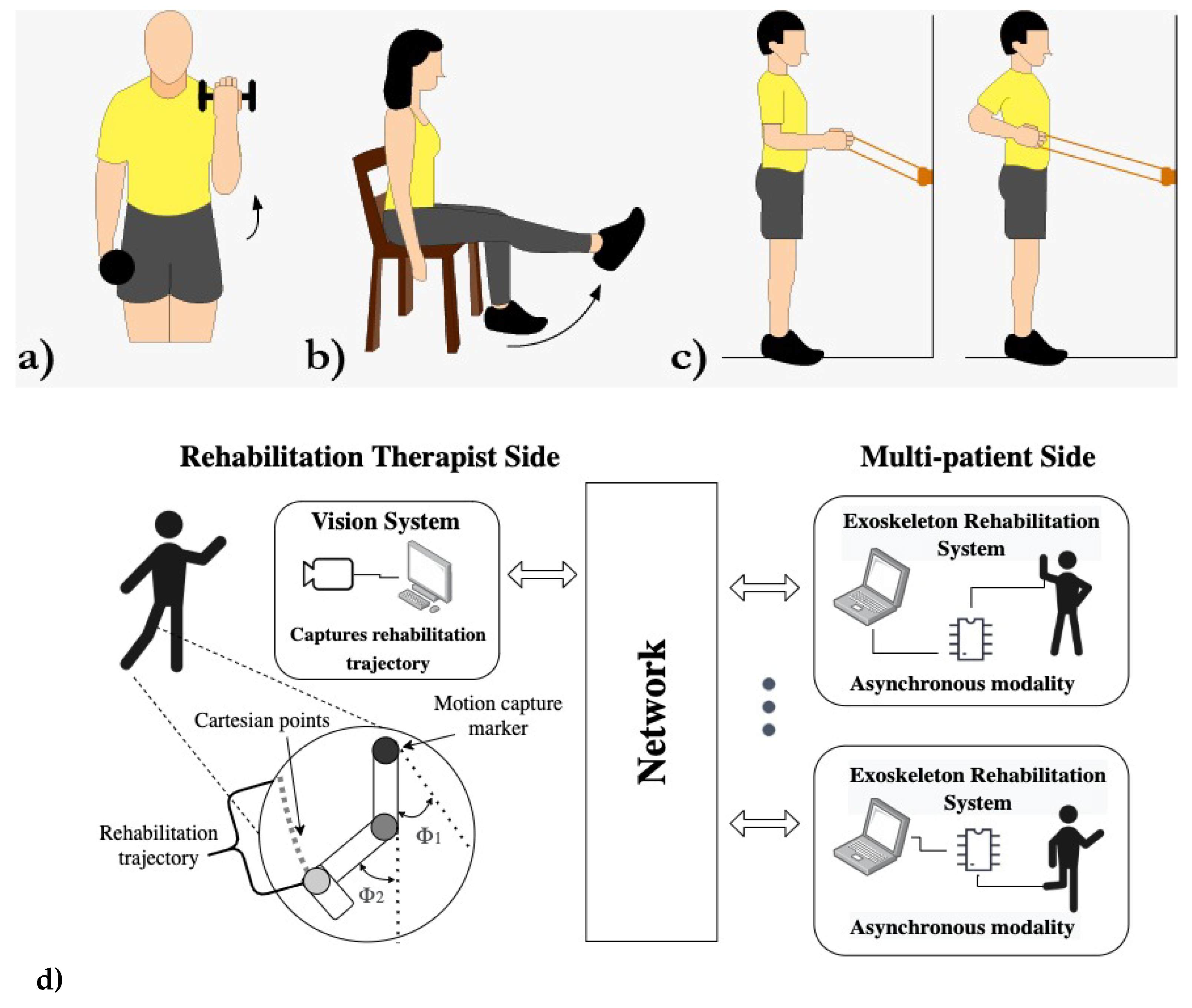
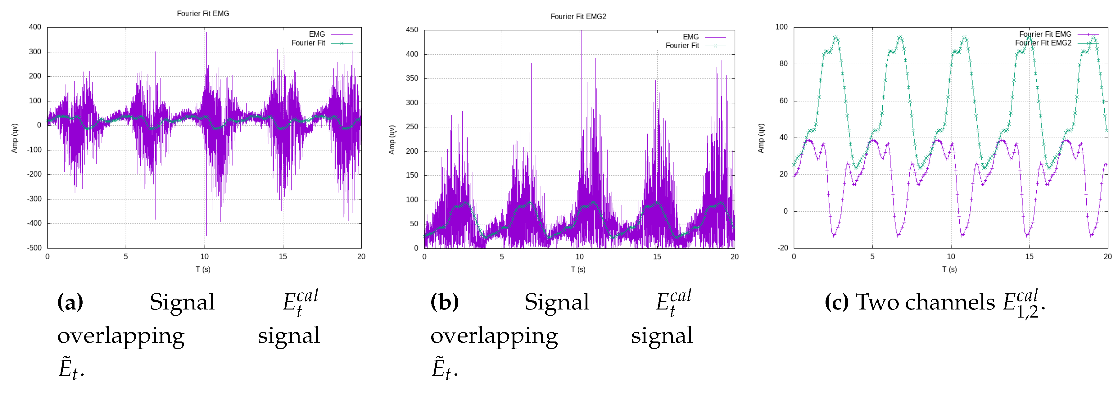
Figure 1abc). The therapist’s rehabilitation exercises are visually assessed and transformed into analytical polynomial Cartesian functions through a least-square fitting approach. A noteworthy innovation presented in this work is the transmission of a concise stream of polynomial coefficients, as opposed to the entire set of Cartesian data. On the patient’s side, these Cartesian polynomials are employed to recreate the therapist’s experimental data with higher resolution. Additionally, by introducing a constant time period, denoted as
T, we achieve the reconstruction of Cartesian components,
x and
y, as periodic functions of time using Fourier series. The integration of Cartesian and electromyography (EMG) data as feedback, similar to the approach in Kang et al. [
9], represents another significant contribution of this work. Notably, our model is designed to infer the posture of Cartesian limbs from EMG signals, allowing for recalibration during new exercises. This feature offers a generalized approach, enabling the control law to adapt to the structure of different exoskeletons simply by readjusting their Jacobian matrices. Furthermore, a linear trajectory smoother model is introduced in cases where patients have biomechanical movement constraints. These smoothing functions facilitate a gradual convergence towards the desired reference trajectory shape. To evaluate the efficacy of the proposed exoskeleton, we conducted extensive simulations involving hundreds of tracking control rehabilitation exercises.
This study introduces a distinctive approach to remote therapy within the realm of tele-rehabilitation. Specifically, it proposes a feedback kinematic tracking model for a networked exoskeleton that undergoes asynchronous visual instruction from a remote therapist. The emphasis lies in transmitting concise streams of polynomial coefficients instead of the entire set of Cartesian data, subsequently transformed into analytical polynomial Cartesian functions. Additionally, the study underscores the integration of Cartesian and electromyography (EMG) data as feedback, facilitating the inference of limb posture from EMG signals and recalibration during new exercises. In the existing literature various approaches within closely related fields of study, including works by [
36,
37,
38,
39,
40,
41], partially intersect with the themes presented in this work. However, the authors remain uncertain as to whether fully analogous studies have been previously published.
The proposed solution specifically focuses on tele-rehabilitation, where a therapist’s exercises are visually assessed and transmitted to the patient’s exoskeleton. The key innovation of the proposed solution lies in the transmission of concise streams of polynomial coefficients, rather than transmitting the entire set of Cartesian data. This approach provides flexibility in tracking and control, making the rehabilitation process highly accurate and efficient. Overall, the proposed solution offers a generalized approach to tele-rehabilitation, making it more accessible and accommodating to a wide range of patient needs. It combines clinical precision with technological sophistication, providing an effective and efficient means of rehabilitation.
The proposed feedback kinematic tracking model for a networked exoskeleton taught asynchronously by a remote therapist is required to ensure accurate, personalized, and efficient rehabilitation for patients, regardless of their location or access to specialized facilities. In addition, it provides i) accuracy and precision: The feedback kinematic tracking model follows the desired trajectory and provides the necessary level of accuracy which is crucial for effective rehabilitation. ii) Adaptability and customization: The feedback model allows for adjustments and adaptations based on the patient’s specific biomechanical needs, and the use of electromyography (EMG) data as feedback allows for the inference of Cartesian posture from EMG signals, enabling recalibration during new exercises. iii) Remote guidance and supervision: Asynchronous teaching by a remote therapist regardless of their location, enables benefits for patients who may not have access to specialized rehabilitation facilities or therapists in their vicinity. iv) Flexibility and convenience: Asynchronous teaching allows patients to perform and follow the prescribed exercises and receive feedback from the therapist at a time that suits them best. v) Efficiency and cost-effectiveness: By utilizing a networked exoskeleton and asynchronous teaching, the rehabilitation process can save time and resources by avoiding frequent visits to rehabilitation centers, while still receiving expert guidance and support.
This paper is structured as follows:
Section 2 delves into the therapist-side tele-rehabilitation, elucidating the teaching process facilitated by a vision system. In
Section 3, we unveil the proposed EMG calibration and observation measurement models. Following this,
Section 4 delves into the exoskeleton’s motion constraints and its kinematic control law. A comprehensive summary of the research’s results is provided in
Section 5. Finally,
Section 6 offers a set of conclusions drawn from this study.
2. Human therapist remote visual teaching
The proposed networked distributed system is structured as an asynchronous tele-system architecture, with the therapist’s side and the patients constituting the client side. The server plays a pivotal role by providing geometric data acquired visually from the therapist’s exercise sessions in front of a camera, transmitted over the network. An artificial vision system captures the data related to the training trajectories taught by the therapist (
Figure 1d, left side).
Notably, the interaction session between the therapist and the patient occurs asynchronously, eliminating the need for simultaneous network connections. This approach stands in contrast to traditional tele-operation methods [
19]. The exoskeleton has the flexibility to connect at any given date and time, allowing the download of therapy exercises in the form of analytic trajectories, represented by coefficients (
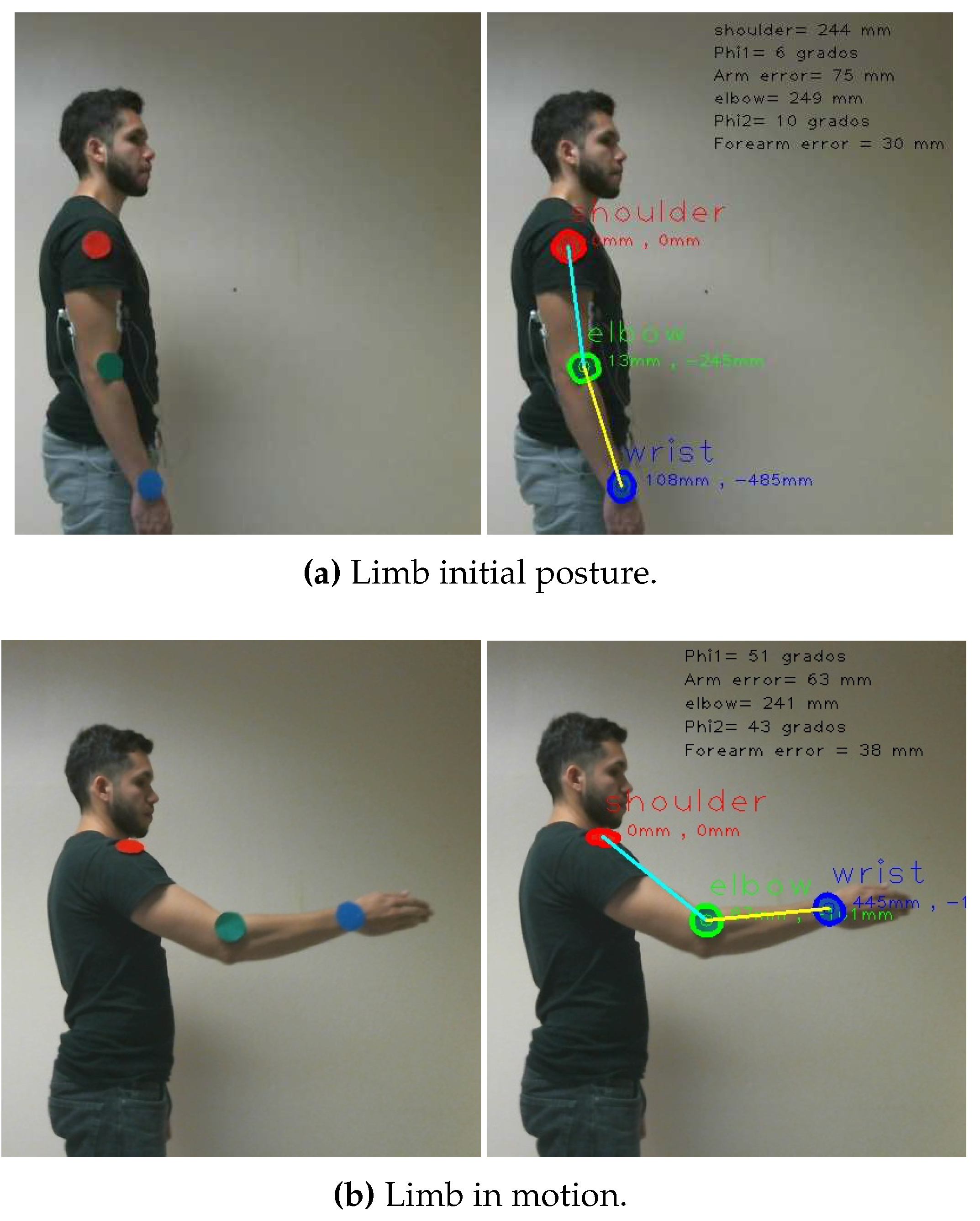
Figure 1d, right side). The server’s computer is equipped with a monocular vision system that accurately measures the angles and positions of colored landmarks strategically placed at the therapist’s limb joints (
Figure 3ab-left). Remarkably, the therapist does not require any specialized equipment during the exercise sessions.
In light of the evident benefits of rehabilitation exoskeletons ([
22]), we selected commonly practiced exercises from a recognized exercise program ([
18]) to serve as the basis for our study. These exercises, whether post-injury or post-surgery, were adopted as trajectories (
Figure 1abc). For example, exercises such as the rotator cuff, shoulder and elbow flexion exercises were employed to teach various motions (
Figure 1ac). Similarly, we incorporated exercises like knee extensions (
Figure 1b) and the stand-up paddle exercise with an elastic band (
Figure 1c) to broaden the scope of our research.
Figure 1.
Tele-training rehabilitation exercises. a)-b) Elbow, knee flexion-extension. c) Shoulder sagittal rotation. d) Telesystem architecture.
Figure 1.
Tele-training rehabilitation exercises. a)-b) Elbow, knee flexion-extension. c) Shoulder sagittal rotation. d) Telesystem architecture.
The proposed tele-system was crafted on standard-capability computers running the Linux Gentoo operating system, version 4.4. The entire codebase was developed using the GNU C/C++ compiler, making extensive use of multiple open-source libraries, including openCV, Armadillo C++, the Open Dynamics Engine (ODE), and Gazebo. Communication between components was facilitated using the TCP/IP protocol via sockets. The vision sensor employed was a cost-effective USB camera (see
Table 1). For the acquisition of EMG biosignals, we utilized the gMOBIlab+ device with two EMG channels. To bring our vision to life, we implemented a virtual exoskeleton prototype with original design mechanisms. This virtual exoskeleton operates under the control of human EMG signals, functioning as a master-slave system.
This work places some emphasis on vision-based teaching. To streamline the measurement process, we strategically position colored landmarks at the joints of the therapist’s limbs, as depicted in
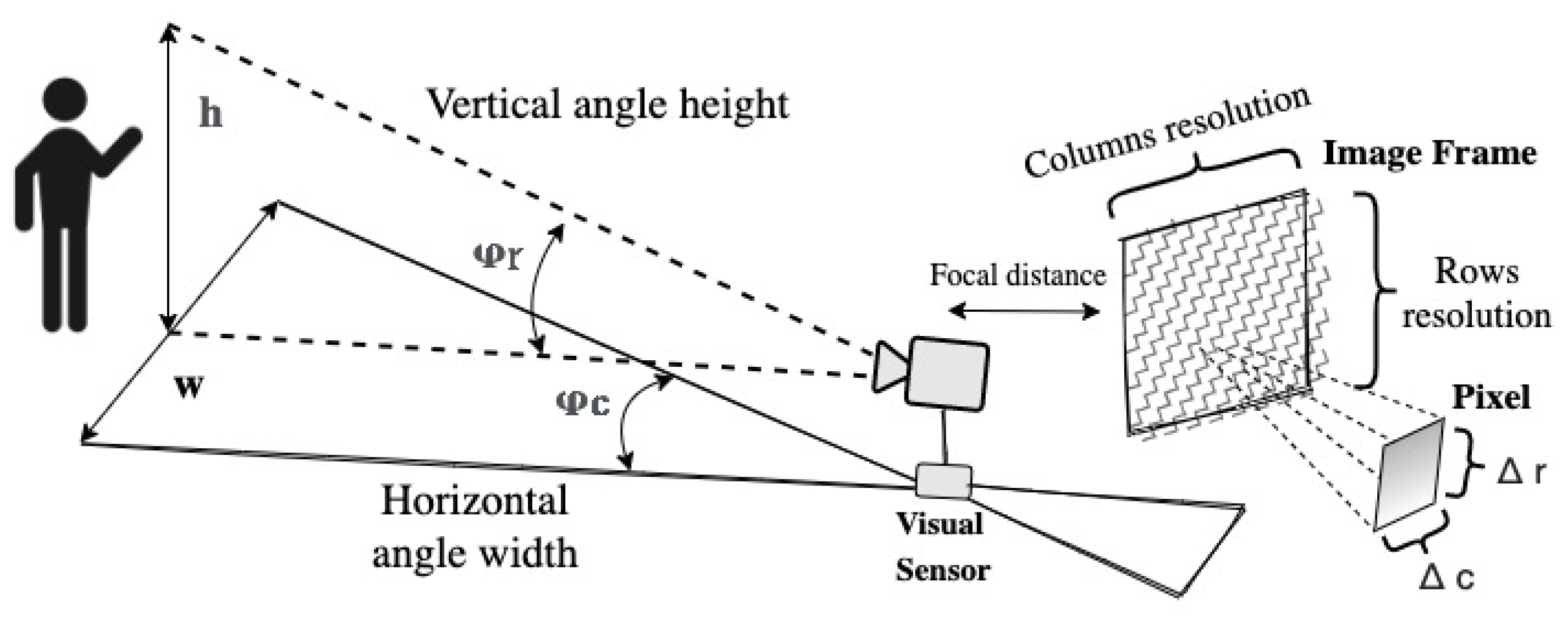
Figure 3. These landmarks serve as the key reference points for measuring angles and positions during exercise sessions. Our approach to measuring the metric trajectories of exercises involves a two-step process. First, we segment the joints’ landmarks based on their RGB color. Subsequently, we employ a nominal resolution geometric model to track the centroid positions of these metric landmarks. In this approach, we establish the reference coordinate system at the location of the visual sensor. In line with the extrinsic parameters outlined in
Figure 2, we define an RGB image as a cubic matrix
, comprising the union of the three primary color channels: red
, green
, and blue
. To extract the shoulder’s landmark, we apply a threshold
to the red channel
and incorporate a zeros matrix
. This process yields a binary segmented image denoted as
and is achieved through the following Boolean equation:
Similarly, the isolation of the elbow’s joint landmark is achieved through the utilization of a binary image denoted as
. The effectiveness of this process hinges on the presence of a critical threshold denoted as
, which assumes a pivotal role in the Boolean criterion:
In a similar manner, the identification of the wrist landmark is carried out through the utilization of a binary image represented as
The determination of this landmark relies on the precise specification of a threshold value denoted as
which is an integral part of the following criterion:
For each segmented region in the images
,
, and
, the position of the landmarks in spatial coordinates is determined by their centroids, denoted as column
and row
, as expressed by:
In this context, the spatial coordinates
and
, where both
and
belong to a segmented region
, represent the pixels within the region. We will now proceed to offer a comprehensive description of the geometric visual model, as depicted in
Figure 2.
Figure 2.
Monocular vision-based geometrical model on the therapist’s side.
Figure 2.
Monocular vision-based geometrical model on the therapist’s side.
Geometrically, the equality for the vertical field of view ((
5)) is valid.
Here,
h represents the height of the object of interest, and
z denotes the metric depth of the human therapist from the camera. Thus, building upon the previous expression, we can determine
, which represents the vertical camera angle quantized in terms of image rows.
With respect to (w.r.t.) the horizontal field of view,
then, dropping off the angle along image’s columns
We estimate the vertical metric resolution factor, denoted as
, as well as the horizontal metric resolution factor, denoted as
1,
Subsequently, we determine the vertical metric position
and the horizontal metric position
of the center pixel
of a landmark.
Next, in the therapist’s side, the superior limb kinematic motion model in 3D space is provided by the expression
where depth is affected by the yaw angle
and double pitch joits
, and
and
to denote the actual metric lengths of the upper arm and forearm, respectively. When representing a 2D exercise scenario, the yaw angle
. Therefore, the depth dimension becomes irrelevant since the arm’s length is not projected, and the trajectory is drawn on a plane in front of the camera. The links
visual measurements,
and
Similarly, we use the variables
and
to denote the joint angles of the limb.
We illustrate a shoulder exercise in
Figure 3, and in
Figure 9, we display the resulting Cartesian trajectory, with red points indicating the Cartesian positions of the blue wrist landmark.
Figure 3.
Visual instruction of various exercises by the therapist.
Figure 3.
Visual instruction of various exercises by the therapist.
In summary, the rehabilitation trajectory, denoted as , is comprised of a set of joint angles and limb parameters and .
In
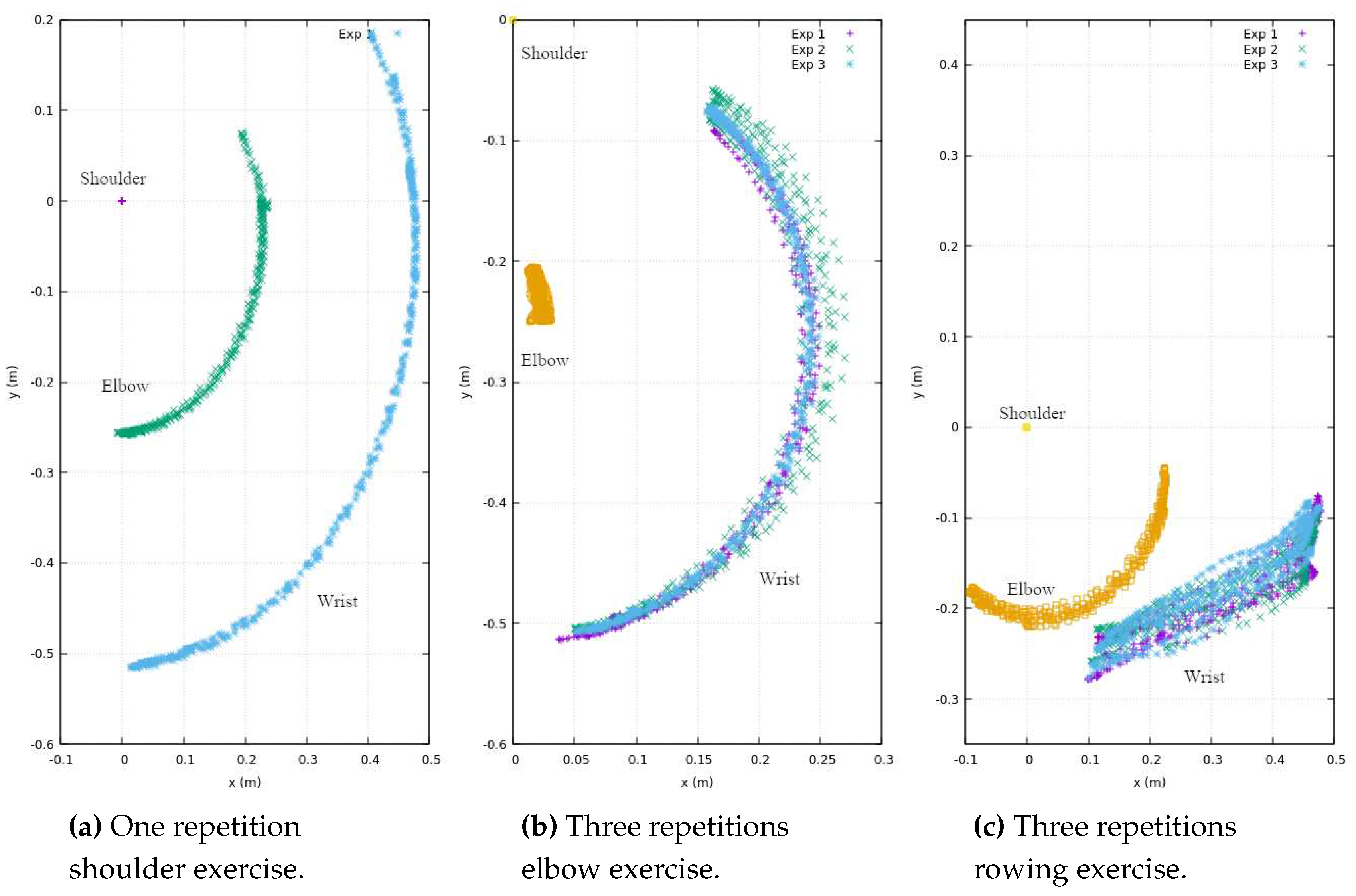
Figure 4, a series of repetitions stemming from exercises performed by the therapist is presented. These exercises encompass a single experimental repetition involving shoulder flexion (depicted in
Figure 4a), along with three experimental repetitions focusing on elbow flexion (illustrated in
Figure 4b). Additionally, three experimental repetitions of a rowing-like motion are depicted (
Figure 4c), wherein both the shoulder and elbow joints operate in unison during the exercise. It is imperative to emphasize that the reference coordinates, denoted as
, are firmly anchored at the centroid of the shoulder.
Additionally, in
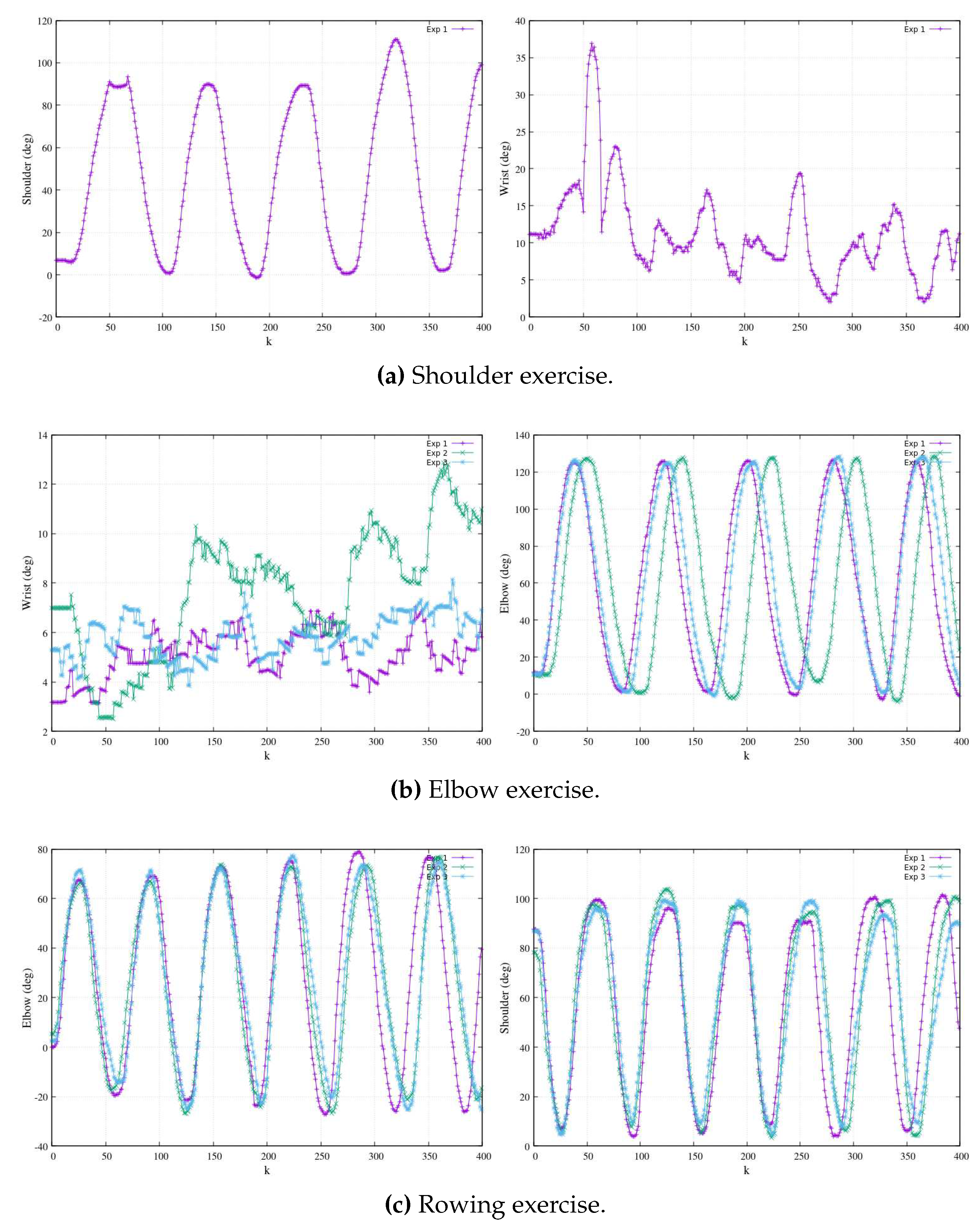
Figure 5, we present angular motion measurements for all joints utilizing visual odometry, with a focus on the
plane. These angular measurements correspond to the Cartesian motion data depicted in
Figure 4. In
Figure 5a (left), we observe an experiment exclusively involving shoulder flexion, where a linear rigid arm is used, and there are a total of five repetitions. It’s important to note that this exercise is the simplest, resulting in data points with a higher degree of overlap. On the right side of
Figure 5a, while still involving shoulder flexion, we observe slight angular perturbations in the wrist, averaging approximately
. These perturbations were primarily caused by minor limb vibrations from the therapist and were further exacerbated by contrast and brightness noise in the measurements.
Figure 5b displays angular measurements for elbow flexion exercises. To ensure clarity without excessive data overlap, we have chosen to present three distinct experiments, each with multiple repetitions. On the left side of
Figure 5b, we observe angular perturbations in the wrist during elbow flexion exercises. Conversely, the right side of
Figure 5b depicts three separate experiments involving elbow-flexion exercises, displaying multiple repetitions that result in periodic oscillations. This presentation highlights variations in speed during the experiments, reflecting biomechanical consistency and differences in execution.
Figure 5c, in its entirety, represents three distinct experiments of rowing-like motions, each of which consists of six repetitions. This comprehensive view enables us to examine the angular dynamics in these exercises in greater detail. On the left side of
Figure 5c, we can observe the angular magnitudes of elbow flexions. Meanwhile, the right side of the same figure portrays shoulder flexions, which synchronize their motion with the elbow flexions. On the therapist’s side, the process involves employing a least square polynomial fitting approach to derive a Cartesian function
. This method is used to process the vision-based 3D measured data, resulting in the determination of polynomial coefficients of the
n-th degree, as described in the following equation:
In this manner, we obtain a parametric function that accurately fits the exercise’s Cartesian data, following a polynomial form:
This approach significantly reduces the trade-off during data streaming to only a few coefficients and the time period
T of one exercise oscillation. These coefficients require a minimal amount of bytes for transmission over the network, thereby mitigating significant time delays.
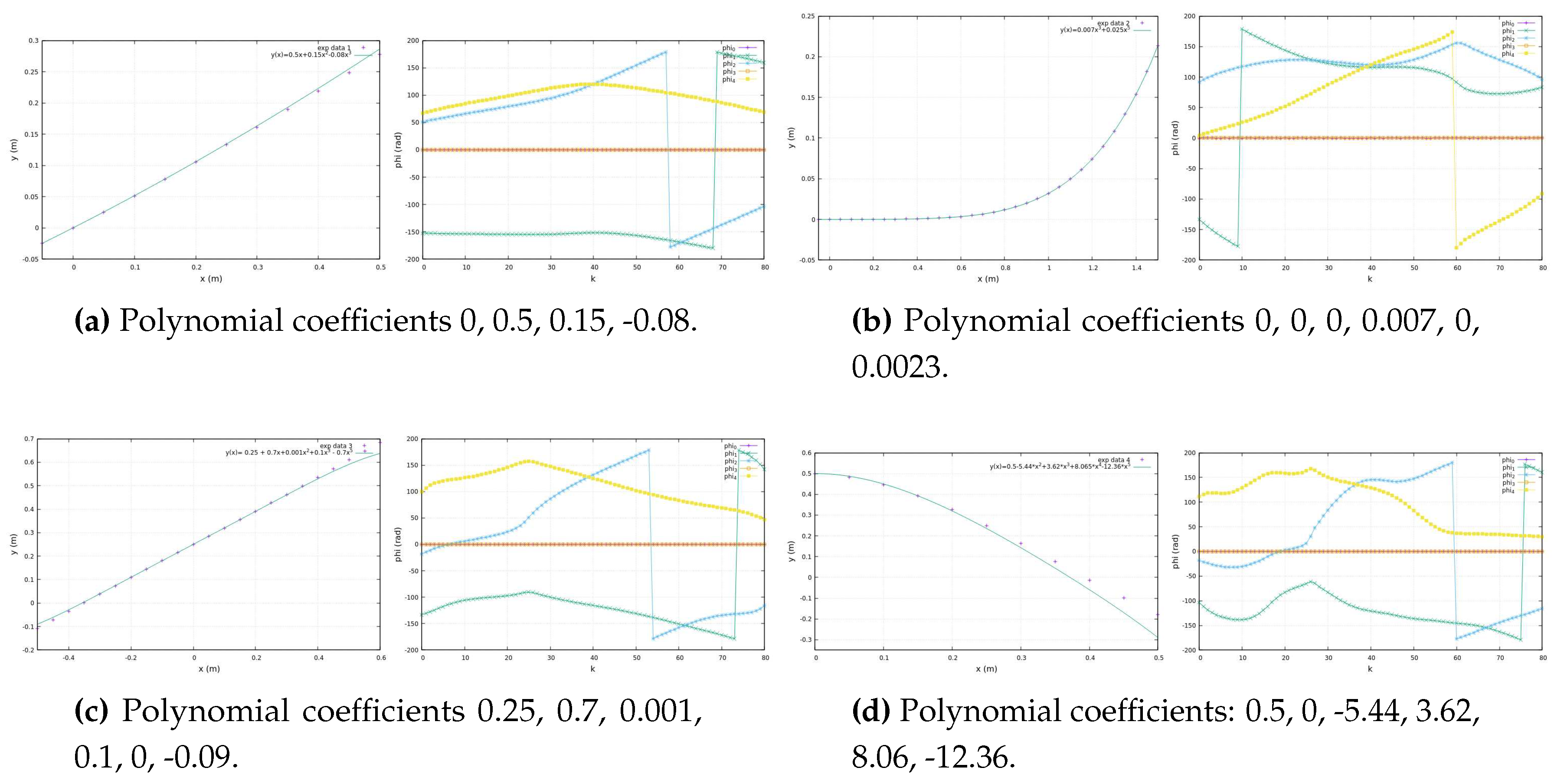
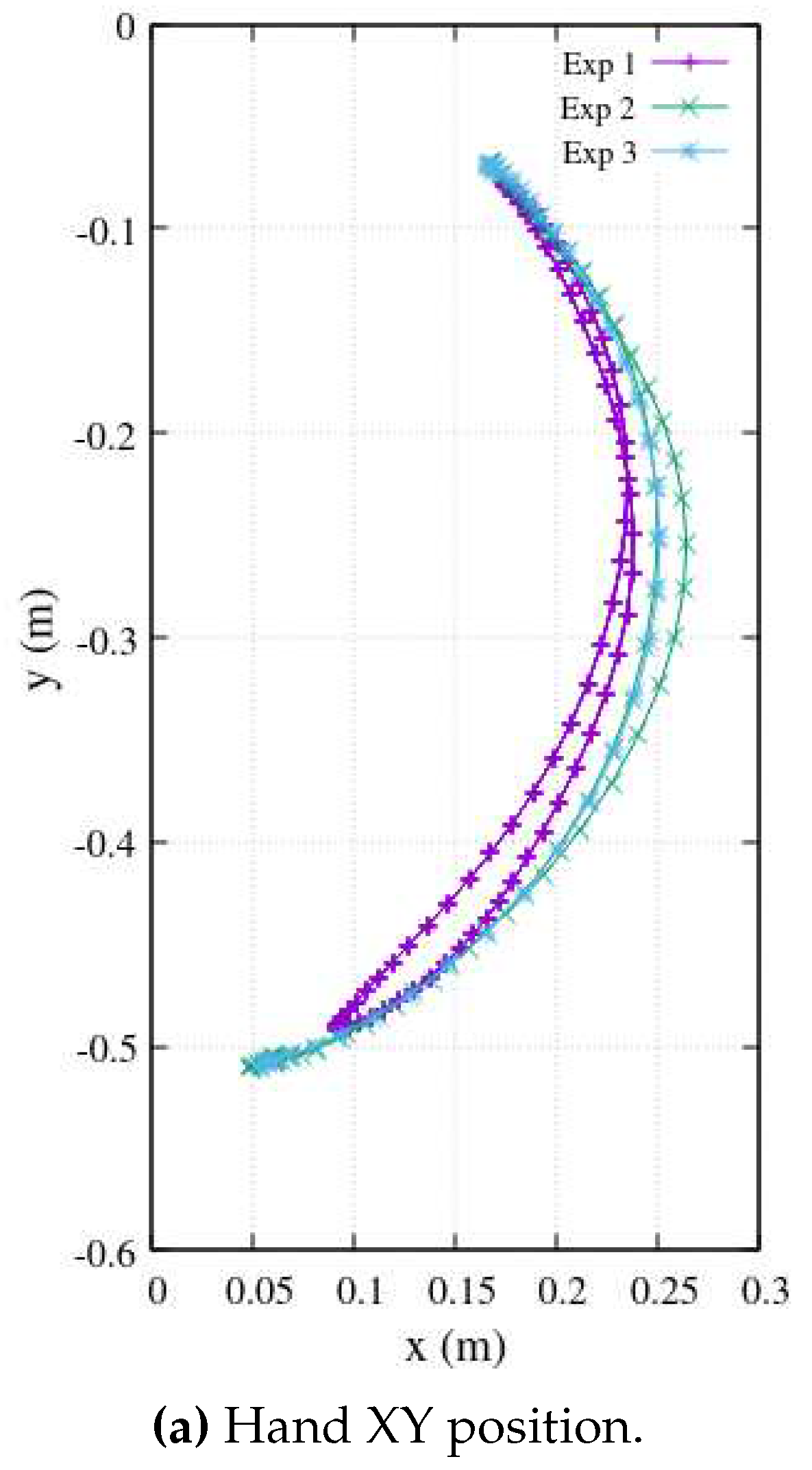
Figure 6 illustrates experimental data from teaching trajectories that have been effectively fitted by various polynomials, exemplifying the practicality and efficiency of this approach.
By representing the exercise trajectory as a continuous polynomial function, denoted as
, available on the exoskeleton’s side, we open the door to the replication of experimental data at higher metrical resolutions. With the time constant of a period
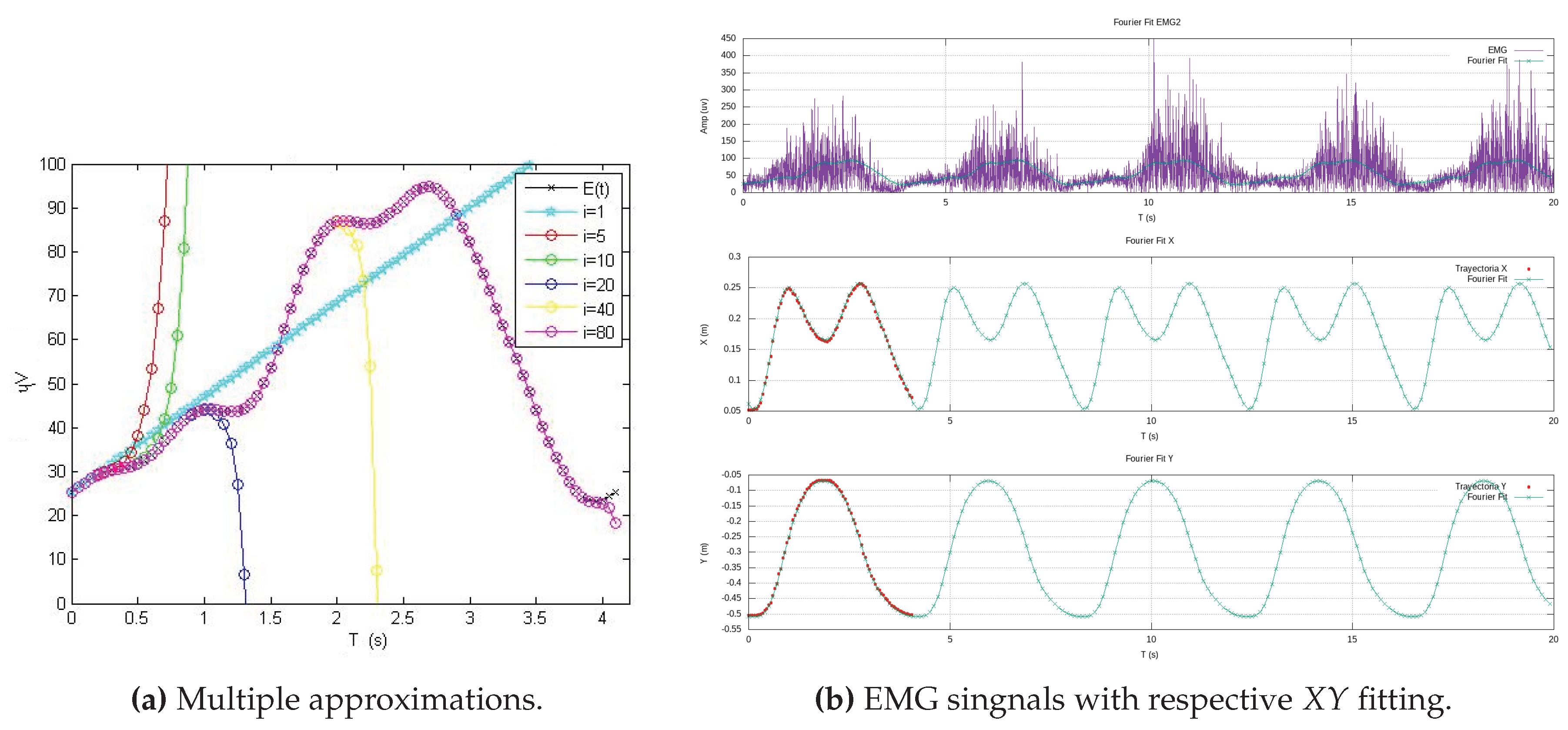
T at our disposal, the exoskeleton’s side can autonomously convert the high-resolution Cartesian data into new components as functions of time. Using Fourier series, we generate new Cartesian components,
and
, as functions of time.
Figure 7 effectively demonstrates this process, showcasing a Cartesian reference trajectory as
versus
, realistically reproducing three experiments involving elbow flexion. This approach, as presented in this work, offers sophisticated analytical functions that serve as effective substitutes for the therapist’s exercises, which typically involve large amounts of experimental data. In doing so, it efficiently addresses the challenges of long transmission time delays and the handling of extensive data tables, ultimately yielding parametric functions that streamline the entire process.
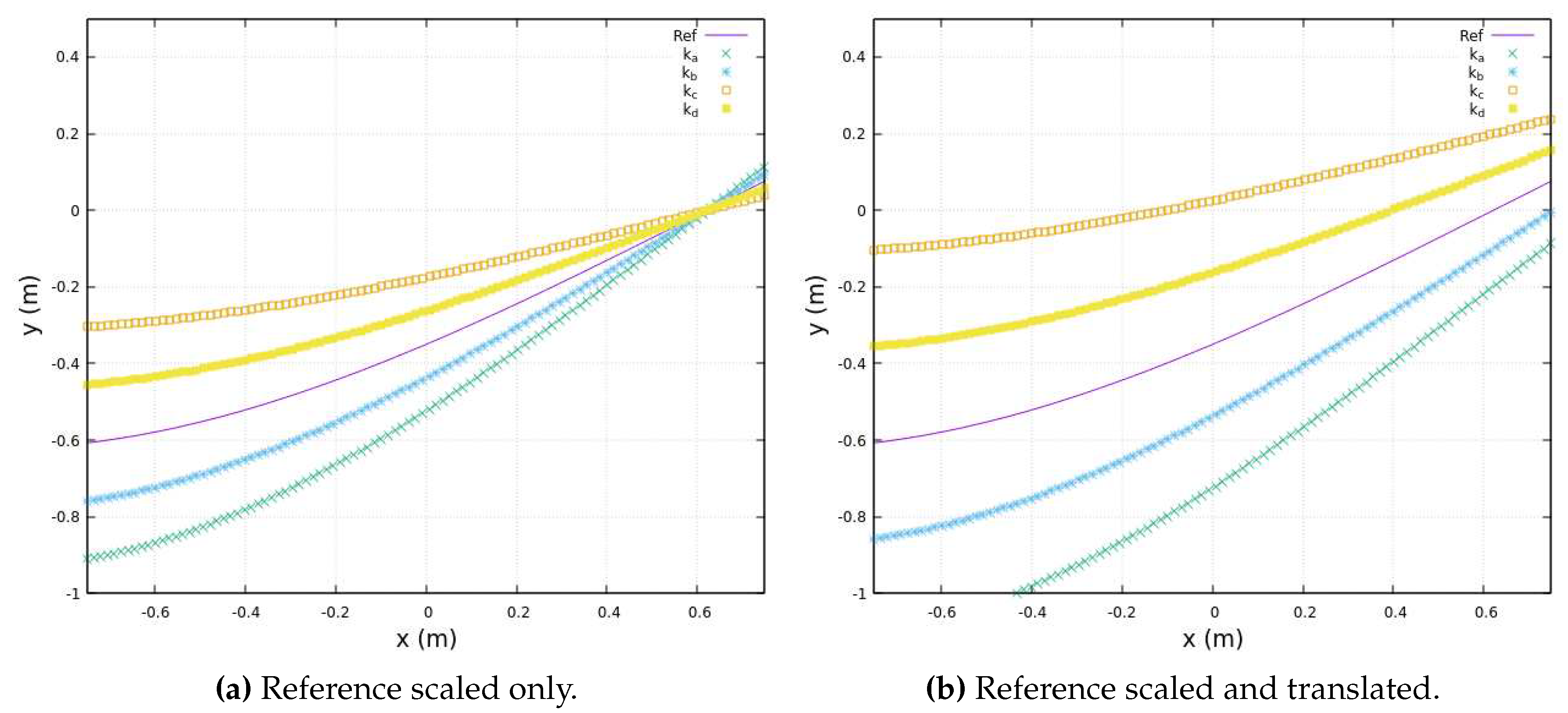
Moreover, in scenarios where biomechanical constraints affecting a patient’s movements are detected during exoskeleton deployment, we employ smoothing functions to facilitate gradual transitions that accommodate these constraints. One such smoothing function, based on a linear approach, is detailed below:
In this equation, the original therapist’s trajectory is regarded as the ideal Cartesian reference motion, denoted as
. Therefore, we introduce two key parameters:
, representing the translation factor of a family of functions, and
, representing the scaling function’s coefficient. When
and
, the exercise function aligns precisely with the therapist’s reference trajectory. However, by adjusting the values of these smoothing coefficients, we achieve gradual convergence toward the therapist’s ideal trajectory.
Figure 8 purposely illustrates various smoothing teaching trajectories that progressively approach the original therapist’s reference trajectory, represented by the continuous line, underscoring the flexibility and efficacy of this approach.
Indeed, it’s important to note that both and are coefficients specific to each exercise trajectory, differences of patient’s limbs size or patient’s motion conditions. The coefficients are manually adjusted individually for different exercises based on the patient’s comfort. This adaptability ensures that the smoothing coefficients are tailored to the characteristics of each exercise, optimizing their effectiveness.
4. Exoskeletons morphology and control law
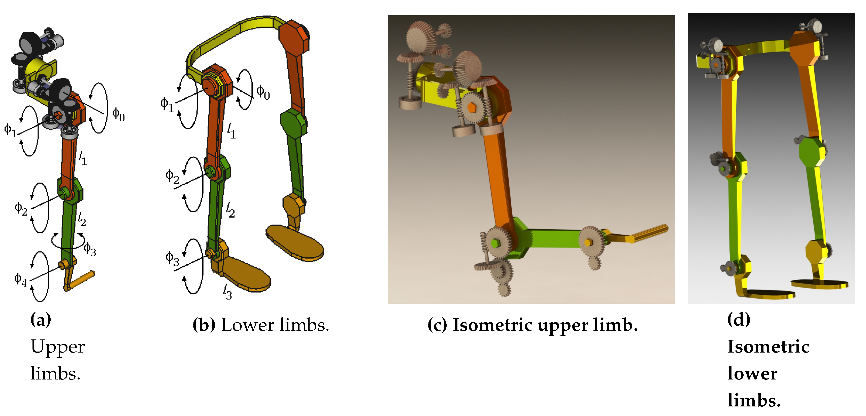
In this study, a proposed exoskeleton model incorporates a well-designed mechanism to facilitate standard rehabilitation exercises (
Figure 18). Alternative methodologies, such as adaptive geometrical design, have been documented in previous literature [
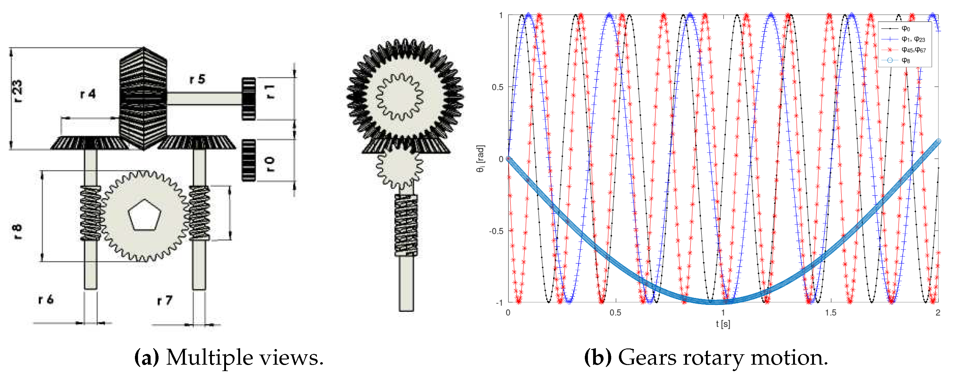
35]. The design of speed reducers (e.g., the shoulder mechanism shown in
Figure 17a) primarily incorporates pulse encoders for joint rotation sensing. These mechanisms are intended to enforce limb tracking along the reference trajectories.
The design assumes all encoders have a constant angular resolution
R [pulses/rev]. The number of pulses
measures the motor’s instantaneous angle
[rad], and its angular speed
[rad/s].
All gears’ rotary speeds are described by (
33) and illustrated in
Figure 17b. Gears with a radius
yield speeds
as functions of the motor’s velocity
,
By expressing (
33) in vector notation, the time-invariant linear system (
34) emerges,
This model encapsulates the functional representation of the joints, providing a framework to deduce Cartesian positions over time for feedback purposes. In
Figure 18, the kinematic parameters of the upper and lower limbs are illustrated, featuring a structured organization of joint axes.
Figure 18.
Exoskeleton mechanism structure.
Figure 18.
Exoskeleton mechanism structure.
Therefore, it follows a dynamic controller at the level of the exoskeleton’s joint gearing, rather than at the level of the limbs’ global kinematic-EMG calibration. Employing an Euler-Lagrange approach, the general Lagrangian model
for the
gear, transmitting rotary kinetic and potential energy, is:
and developing the following differential equation
Subsequently, by considering and substituting joint kinematics from (
34), and simplifying in terms of controlled motor motion
, the following dynamic vector
is deduced,
Expressing
in terms of the explicit vectors for inertia
and gravity force
,
and expressing this relationship in vector notation, the following dynamic equation is formulated,
It follows that a controller is deduced from the dynamic equation (
39). Thus, rewriting the torque vector with a differential equation notation,
and by separating different differentials,
solving by definite integration,
then by algebraically arranging and changing subindex notation, a model-based controller is yielded
where
is the inertia vector pseudoinverse
2. Thus, the speeds of the exoskeleton’s joint mechanisms are recursively controlled according to a specified reference torque
.
4.1. Limbs kinematic model
Based on the mechanical model presented in
Figure 18, a set of Cartesian equations was deduced for kinematic analysis, forming the foundation for position control. The non-linear and non-square systems obtained in (44) and (45) evidently lack inverse analytical solutions. Therefore, an algebraic numeric recursive approach was developed. Expressions (
44a)-(
44c) describes the upper limb kinematics of the 5 rotary joints. Notice that
and
are rolling axis. Thus, for
x,
for coordiante
y
and for coordinate
z,
Expressions (
45a)-(
45c) are the kinematic equations of the lower limb with 4 rotary joints,
and
and
The instantaneous
Jacobian matrix represents the rate of change of coordinates
w.r.t. the joint-space vector
of length
n. Such that,
For the upper limb the
Jacobian matrix elements are
and for
y,
and for
z,
Likewise, for the lower limb, the
Jacobian matrix terms are
and for
y
and for
z
4.2. Recursive time-variant control law
Other exoskeleton control approaches have addressed nonlinearity using sliding surfaces [
29] or adaptive methods, implementing impedance with feedback using biosignals [
30], and neural approximation [
31].
The present work takes an approach involving a model-based algebraic linear recursive system of equations. This work deduces a time-variant redundant kinematics controller since is considered. The model incorporates the reference trajectory provided by the therapist, denoted as . The real-time feedback utilizes the EMG observation . The innovation model, representing the local reference, is the inverse model , and the updating model involves the encoders’ observation .
Let us define the state linear equation (
70) as the first-order derivative forward kinematics.
and stating this expression in the form of differential equation, its derivative-order decreases
completing all differentials with their respective integrals at both sides of the equality
therefore, the expression (
73) is the general recursive solution,
Therefore, from such an equality the expressions (74) lead to forward/backward general solutions.
The recursive forward:
and the recursive backward:
Therefore, the inverse general model for the recursive control law is set by an ideal global trajectory
,
Some terms in the model are expanded. Since the Jacobian is non-squared, a pseudoinverse matrix solution is applied,
and the forward solution has the next local reference
,
Where the exoskeleton’s joints direct measurements are obtained from encoder devices,
When the error condition
is met, the control loop achieves goal tracking.
Figure 19a illustrates a complex trajectory and its tracking control performance concerning the joint angles (
Figure 19b). Additionally,
Figure 19c depicts the evolution of position metric errors throughout the entire reference trajectory.
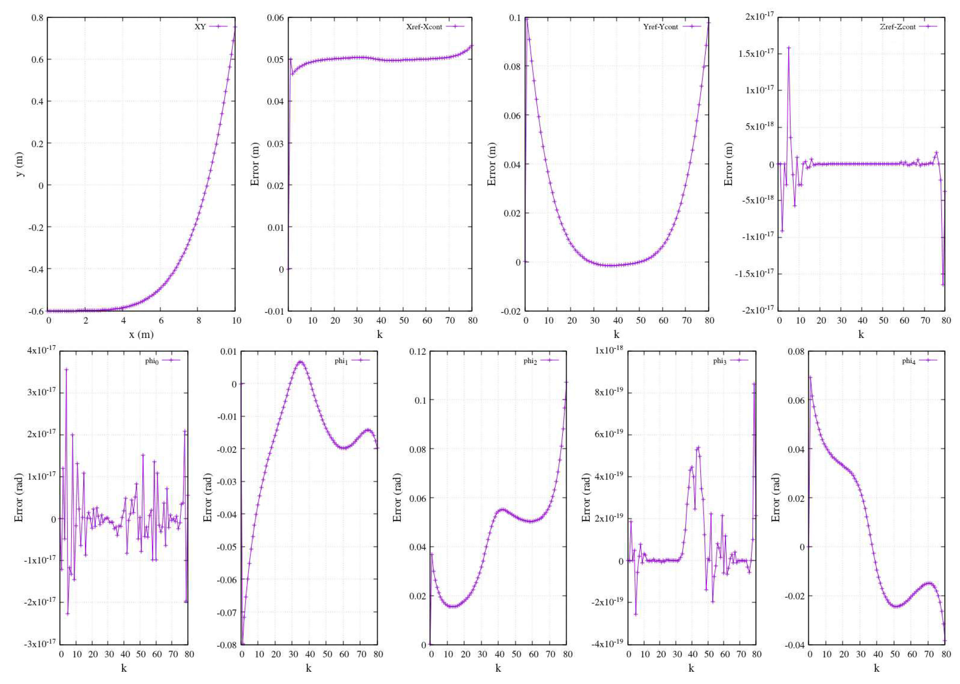
In the context of numerical simulations for numerous controlled trajectories, the efficacy of the control approach was validated through a comparative analysis against a reference ideal function. The trajectory in
Figure 20-above illustrates an
path with an arbitrary reference defined as
. Along the same row of the figure, the plots elucidate the error between the reference function and the controlled function. Ideally, a precise match is anticipated between the two functions. The observed errors in the
x and
y components, in general, are relatively small. As for the
z component, its error is nearly zero since this trajectory is intentionally planar, confined solely to the
plane. Consequently, any variation along the
z axis should be virtually null. This illustration underscores the expectation that the controlled functions accurately align with a segment of a 5
th-grade polynomial function.
Moreover,
Figure 20-below displays the resulting errors in joints’ angles induced by the trajectory in the same figure (expressed in physical units as radians).
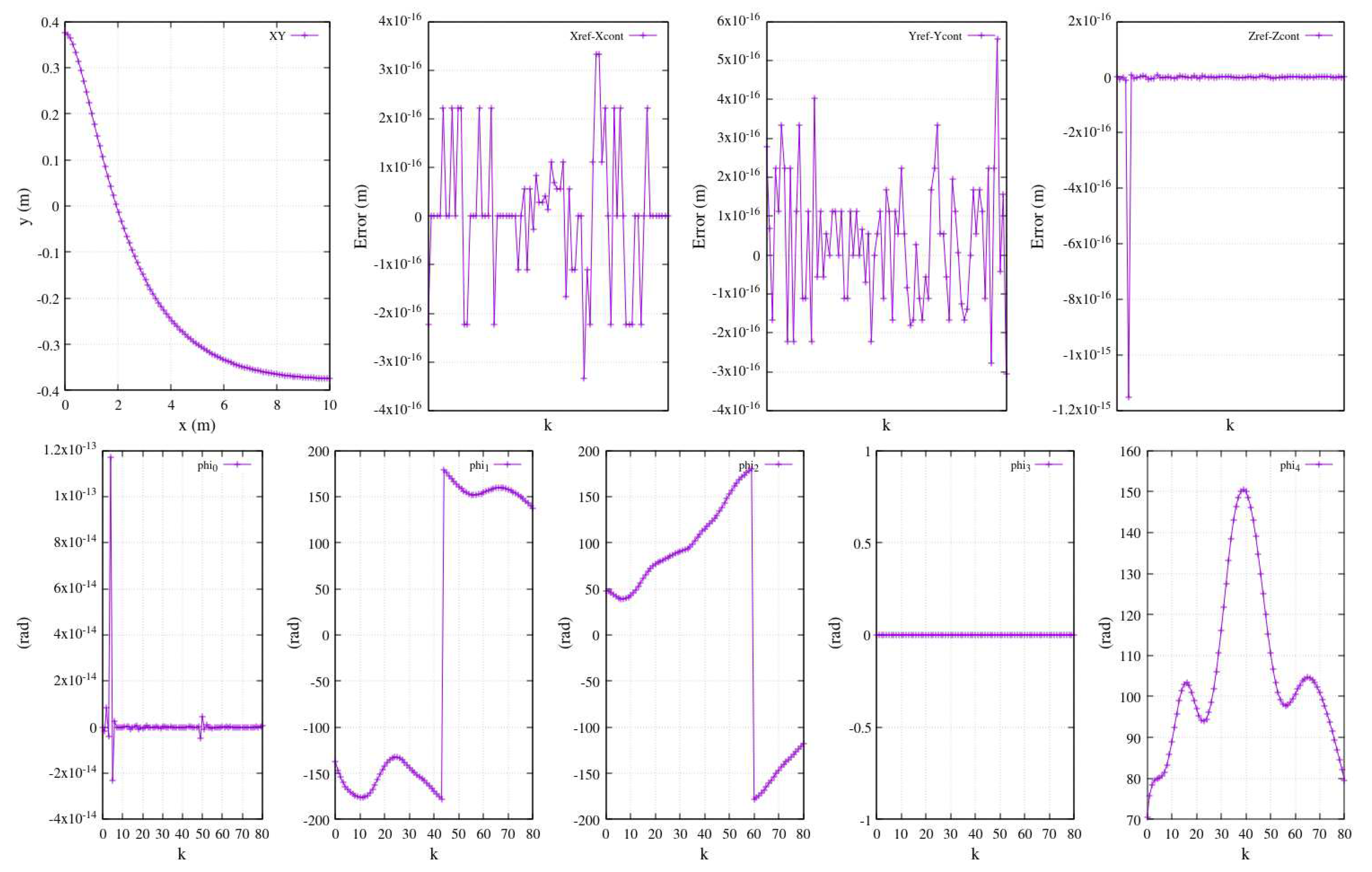
A comprehensive depiction akin to
Figure 20, showcasing the entire joint performance, is presented in
Figure 21. A distinct range of coordinates from a different reference function is established as the reference trajectory, with the framework’s origin situated at the shoulder centroid. Similarly,
Figure 21-above exhibits a Cartesian plot along with the errors along the three axes (reference versus controlled function).
Figure 21-below illustrates the joints’ angle performance resulting from the controlled tracking trajectory.
5. Results and discussion
Summarizing the core focus of this work, we direct our attention to the following three figures:
Figure 22,
Figure 23, and
Figure 24. These figures encapsulate the fundamental purpose and achievement of this study. They provide a visual representation of the work’s primary objective, which is the estimation of joint angles from EMG measurements. For the sake of clarity and simplicity, the plots in these figures display data for two key joint angles, highlighting the remarkable success of the approach.
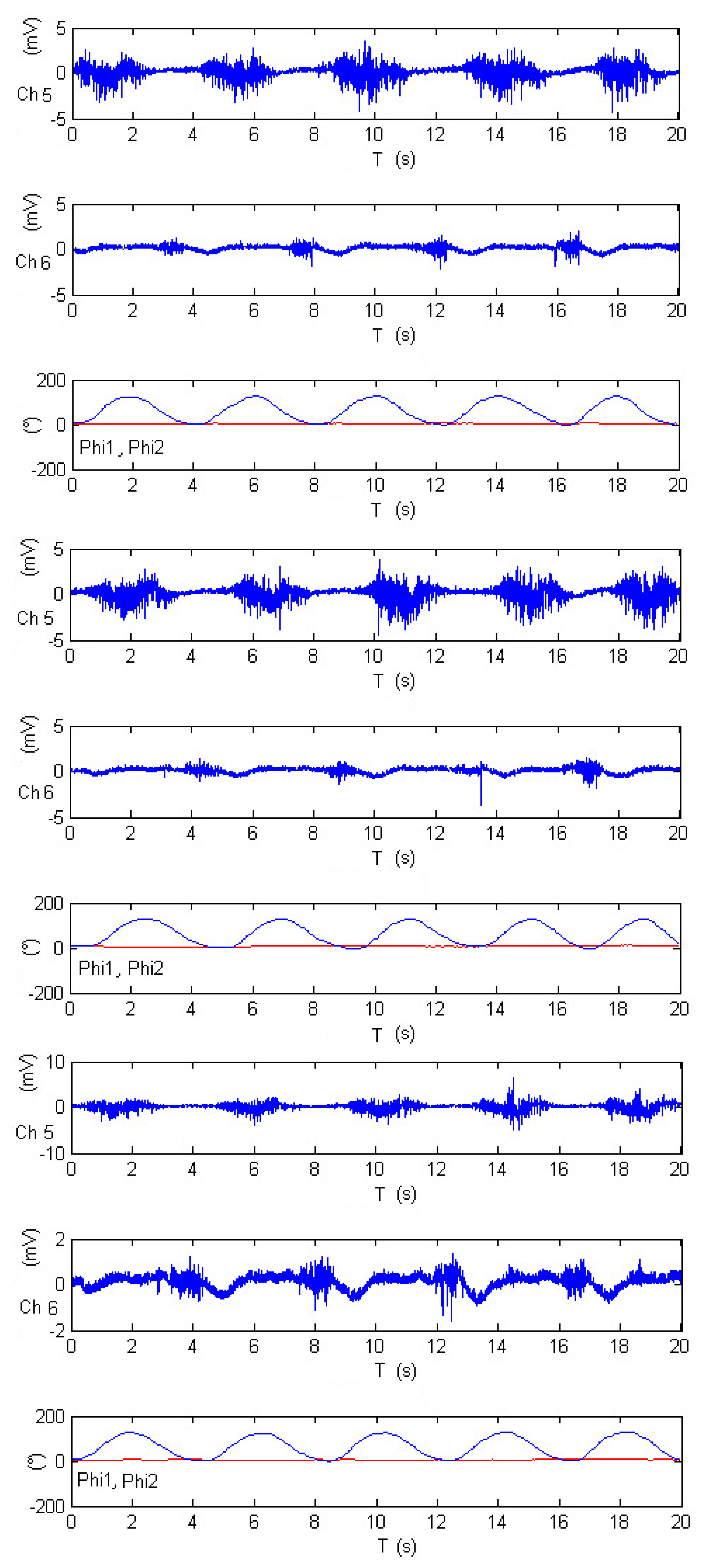
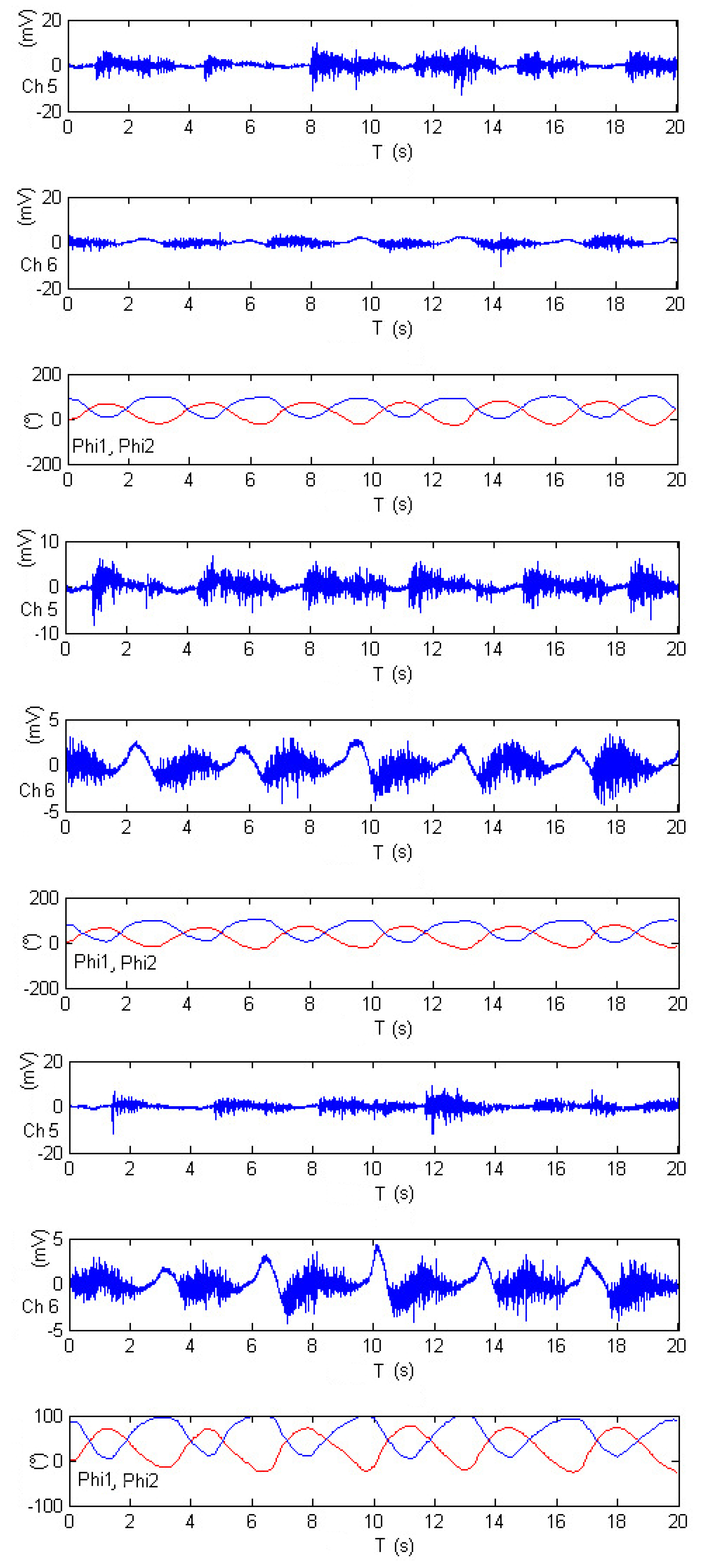
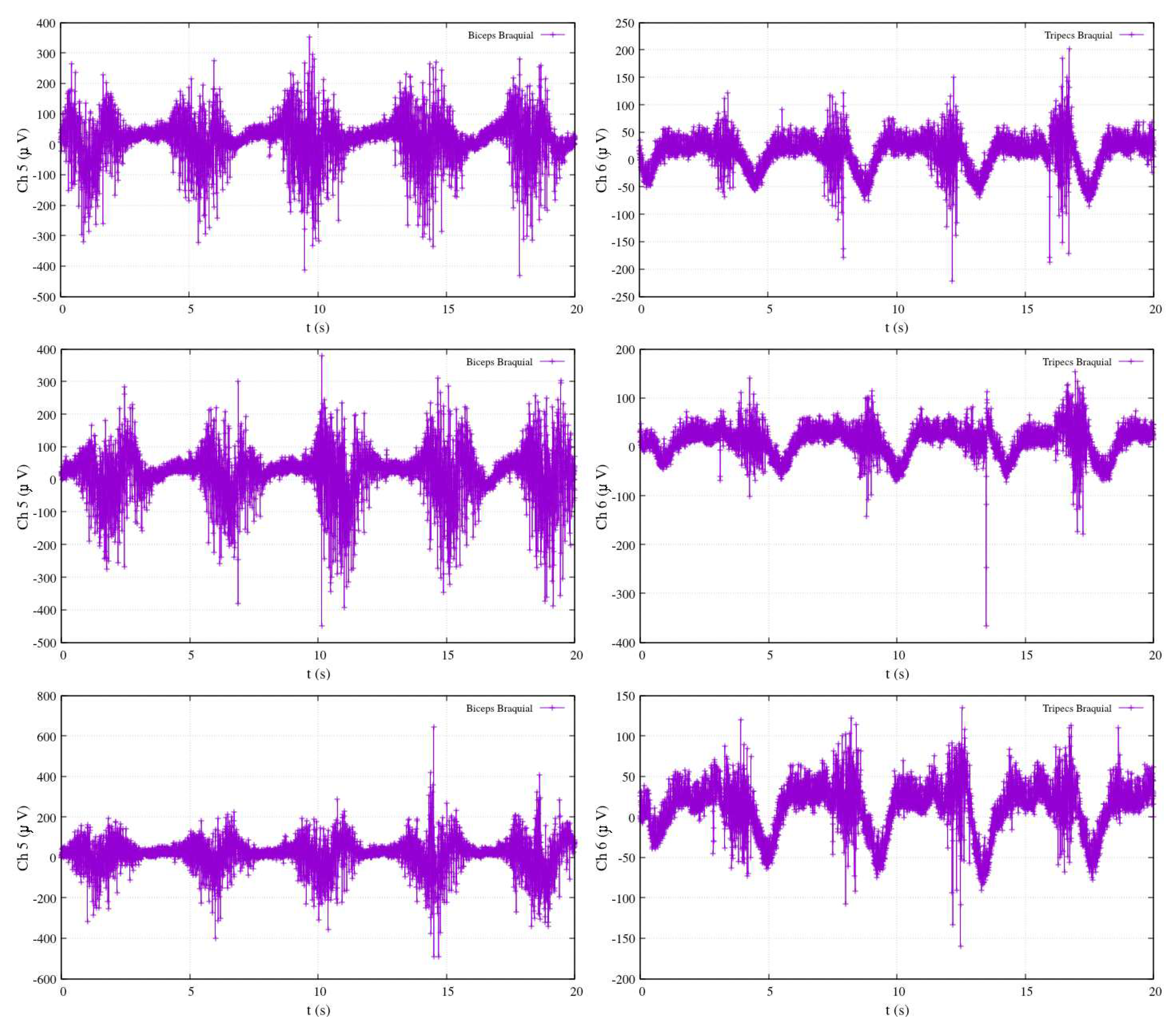
Figure 22 presents data from three distinct experiments involving elbow flexion. Within this figure, the shoulder angle is denoted as
(depicted in red), and the elbow angle is represented as
(in blue). Two specific channels, Ch5 and Ch6, correspond to the electromyography measurements of the biceps brachii and triceps brachii, respectively. The selection of these two channels reflects the authors’ recognition of their suitability for assessing electromyography activity during limb motion.
Following the calibration process, the results in
Figure 22 demonstrate that the activity associated with elbow flexion (depicted in blue) reveals a strong correlation between the elevation angle and the measurements from Ch5, emphasizing the crucial role of the biceps brachii in this motion. Conversely, the decrease in the elbow’s angle is found to be correlated with the measurements from Ch6, highlighting the impact of the triceps brachii. Interestingly, the motion of the shoulder joint (
) is not detected within this specific configuration, as indicated by the red-colored plot. This observation sheds light on the distinct contributions of the two channels to the control of different joint angles.
Figure 22.
Calibrated EMG measurements, estimation joints’ angle and in elbow-flexion performance.
Figure 22.
Calibrated EMG measurements, estimation joints’ angle and in elbow-flexion performance.
Figure 23 offers a close look at an experiment comprising five repetitions of shoulder flexion. Within this figure, the shoulder angle continues to be represented as
, depicted in red, while the elbow angle is identified as
and shown in blue. The electromyography measurements are captured by channels Ch5 and Ch6, corresponding to the activity of the pectoralis major and anterior pectoralis muscles, respectively. Following the calibration process, the results in
Figure 23 reveal that during shoulder flexion activity (as depicted in the red-colored plot), the elevation angle is strongly influenced, with substantial contributions from both Ch6 and Ch5 measurements. This highlights the role of both the anterior pectoralis and the pectoralis major muscles in controlling the shoulder’s elevation angle.
However, as the exercise primarily involves shoulder motion and maintains the elbow at a fixed position, the motion of joint
is not detected in this particular configuration, as indicated by the blue-colored plot. This distinction further underscores the remarkable accuracy of the approach in distinguishing the contributions of different muscle groups to specific joint movements. Overall,
Figure 23 demonstrates the successful application of electromyography measurements in estimating joint angles, exemplifying the adaptability and precision of this approach for diverse exercises involving multiple joints.
Figure 23.
Calibrated EMG measurements, estimation joints’ angle and in shoulder-flexion performance.
Figure 23.
Calibrated EMG measurements, estimation joints’ angle and in shoulder-flexion performance.
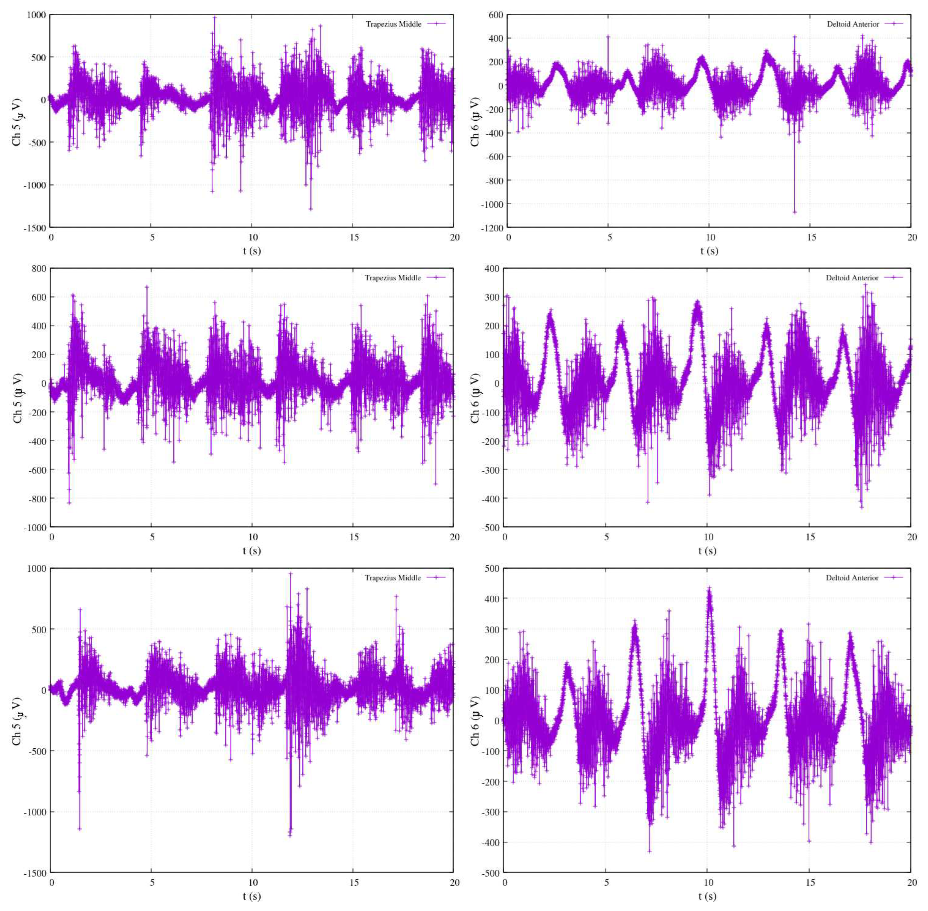
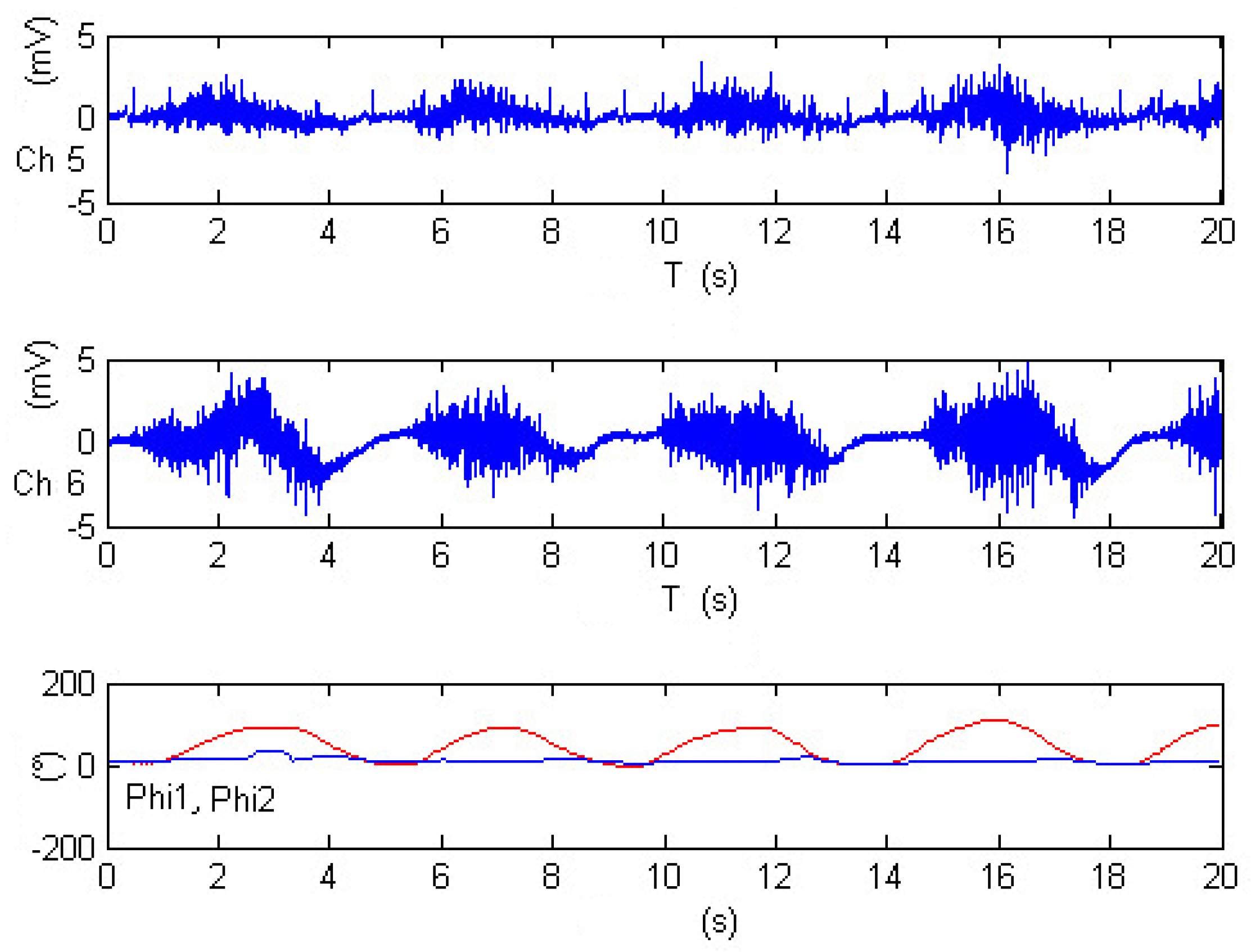
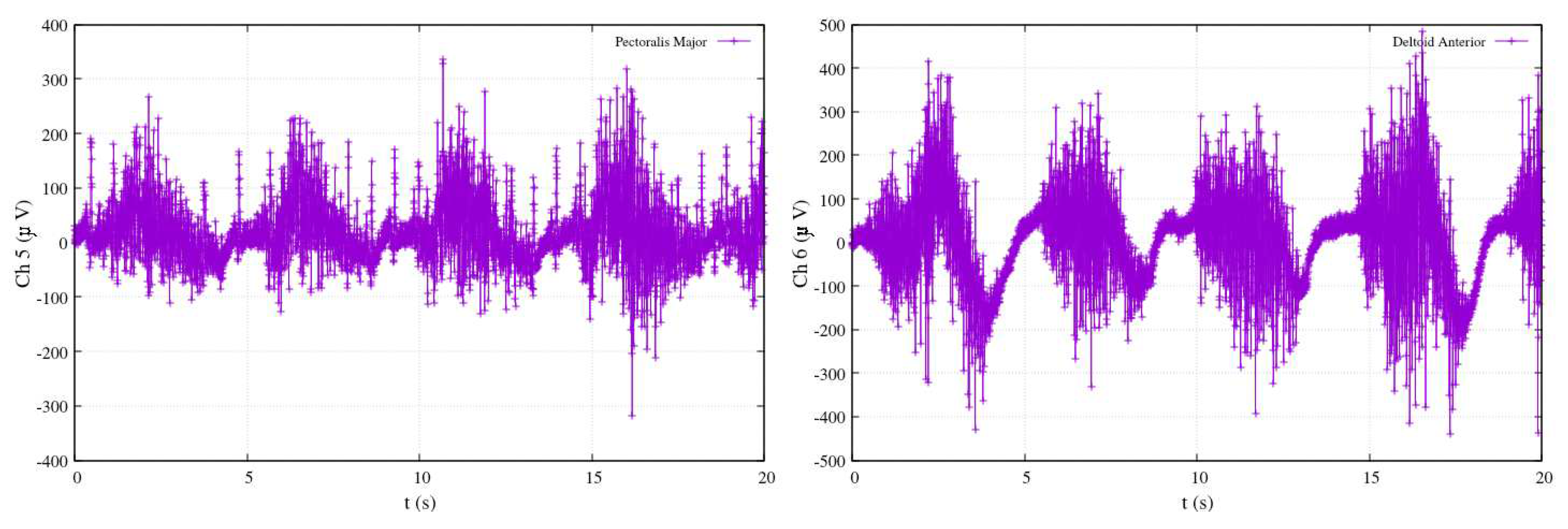
Figure 24 offers insight into three distinct experiments involving rowing-like flexion, wherein both shoulder and elbow joints exhibit synchronized motion activity. As in previous figures, the shoulder angle is denoted as
, represented by the red-colored plot, while the elbow angle is identified as
and displayed in blue. The electromyography measurements for these experiments are derived from channels Ch5 and Ch6, corresponding to the activity of the middle trapezius and anterior deltoid muscles, respectively. After calibration, the results within
Figure 24 reveal that elbow flexion activity (illustrated by the blue-colored plot) exhibits different oscillatory angular phases. The data suggests that the elevation of
appears to be significantly impacted by Ch5 measurements, while
is influenced by Ch6 data. The remarkable consistency observed across these three experiments serves to validate the proposed approach in this research, showcasing the method’s ability to accurately estimate joint angles during complex exercises that involve synchronized motion of multiple joints. This validation is a testament to the reliability and effectiveness of the approach, underscoring its potential for real-world applications in the field of tele-rehabilitation.
Figure 24.
Calibrated EMG measurements, estimation joints’ angle and in rowing-like flexions performance.
Figure 24.
Calibrated EMG measurements, estimation joints’ angle and in rowing-like flexions performance.
Table 3.
Physics-based computer simulation parametersa.
Table 3.
Physics-based computer simulation parametersa.
| Limbs: |
|
|
|
| m=1 kg |
kg
|
kg
|
kg
|
|
m |
limbs m |
Nm |
|
| Gears: |
|
|
|
|
m |
m |
m |
m |
|
m |
(threads) |
(teeth) |
kg |
|
kg |
kg |
kg |
kg |
|
kg
|
kg
|
kg
|
kg
|
|
kg
|
|
|
|
|
aGazebo enabled with Object Dynamic Object (ODE). |
Although this study does not address more intricate rehabilitation types, the showcased exercises are representative of typical rehabilitation routines, serving as a testament to the feasibility of the proposed method. Currently, the demonstration of the model’s applicability is achieved using only two EMG channels. Given the limitation of relying on a singular visual sensor, the integration of various technological sensing devices becomes imperative. This broader array of sensing devices aims to encompass diverse perspectives surrounding the therapist’s tasks, thereby enhancing the overall accuracy of measurements. In the context of trajectory adjustment for the linear trajectory smoother model, a manual trial-and-error approach is employed to fine-tune the trajectory parameters, specifically and .
6. Conclusion
In this comprehensive research endeavor, a remarkable paradigm shift was introduced in the realm of tele-rehabilitation. The proposed approach has a feature: allowed for asynchronous interactions, removing the constraints of rigid scheduling, as exercises could be conducted at different dates and times, making rehabilitation more accessible and flexible for patients. The patient-exoskeleton interface was engineered to receive concise data structures, and the innovative use of coefficient sets emerged as a masterstroke. These sets proved invaluable in ensuring that data streaming remained swift and uninterrupted, unfazed by the passage of time. One of the standout features of this work was the treatment of all exercises as periodic functions. This approach enabled the seamless application of Fourier series fitting, providing an elegant and efficient means of data representation. The ability to translate complex exercises into Fourier series representations presented a new dimension of flexibility in tracking and control.
A cornerstone of this research was the method for reproducing rehabilitation exercises using Cartesian analytical polynomials. This method unlocked the door to producing high-resolution functions of time by synthesizing Cartesian functions of time with EMG data, with time itself serving as the universal synchronization variable. This synthesis represented the union of clinical precision and technological sophistication, making the rehabilitation process more accurate and efficient. A novel model for inferring Cartesian posture from EMG signals was an important issue of this work, showcasing remarkable reliability. The need for recalibration with each new exercise served as a testament to the adaptability and responsiveness of this approach, ensuring that the exoskeleton remained in sync with the patient’s unique characteristics and movements.
The proposed exoskeleton underwent rigorous simulation testing, encompassing hundreds of tracking control rehabilitation exercises. Its adaptability was underscored by a control law that could be seamlessly adjusted to suit various exoskeleton structures, simply by readjusting the Jacobian matrix. This adaptability introduced an exciting degree of versatility and expandability in the application of this technology, not limited by specific hardware constraints. In essence, this simulation prototype, anchored by a single reference trajectory, demonstrated remarkable potential in the calibration of numerous EMG experiments and the execution of multiple tracking control exercises. The system’s adaptability, efficiency, and the profound impact it could have on the field of tele-rehabilitation were evident throughout this research. The approach outlined in this study promises to redefine and enhance the way rehabilitation is conducted, making it not just more effective but also more accessible and accommodating to a wide range of patient needs. It represents a significant step forward in the integration of technology and healthcare, and its implications are bound to be felt for years to come.
As a future work, enhancing the visual teaching process can be accomplished by substituting the RGB camera with either an RGB-D or a ranging laser device. This alternative not only mitigates noise but is also impervious to constraints and illumination variations, offering the added advantages of infrared capabilities and 3D cloud data provision. In addition, to ensure the linear trajectory smoother model’s optimal performance, automatic optimization methods and tuning of rehabilitation trajectories, facilitated by parameters and , will enable a systematic convergence toward the desired reference trajectory shape. In our forthcoming work, there is an envisioned redesign of the exoskeleton mechanism. This redesign incorporates elastic soft materials, mimicking artificial muscles activated by electrical/optical signals, preserving EMG feedback. In addition, addressing the expansion of the EMG device array is pivotal, allowing for the comprehensive mapping of additional body muscles while utilizing more compact technological devices. We posit that exploring alternative controllers is imperative for achieving enhanced performance, tailored to different rehabilitation tasks, fostering a more nuanced understanding of optimal controller-task relationships.
