Preprint
Article

Microstructure, Phase Evolution and Mechanical Properties of As-Cast and Quenched Ti-Mo-Fe Alloys

Submitted:

23 January 2024

Posted:

24 January 2024

You are already at the latest version

Abstract
The present study conducts the phase analysis, microstructural characteristics, and mechanical property evaluation on the as-cast and quenched Ti-15Mo-xFe alloys with high iron content ranging from 4 to 12 weight percent. All the four alloys were produced in a button-arc melting furnace. Heat treatment in the form of solution treatment was performed in a muffle furnace at a temperature of 1100°C, with a 1-hour holding time. The samples were rapidly quenched in ice-brine. Various characterization techniques were used to analyze samples both in the as cast and quenched conditions. X-ray diffractometer (XRD) was used to analyses the phases present in each alloy whereas the optical microscope (OM) was employed to track the microstructural evolution. The mechanical properties of the alloys were evaluated using a tensile test method while the micro-Vickers hardness measurements were conducted to evaluate hardness of the alloys. OM micrographs revealed equiaxed β grains and substructures in as-cast TMF0, dendritic structure, and equiaxed β grains with pores forming around the grain boundaries in TMF1, and micrograph full of dendrites and pores was observed in the as-cast TMF2 and TMF3 alloys. The quenched TMF0 showed only β equiaxed grains whereas TMF1, TMF2, and TMF3 revealed micrographs full of equiaxed grains of β phase with pores throughout the grain boundaries. The XRD patterns of cast TMF0 showed peaks belonging to the β and orthorhombic α″ martensitic phases and the quenched sample showed the bcc β phase only. The TMF1, TMF2, and TMF3 alloys in as-cast condition indicated peaks belonging to β , α″ and intermetallic B2 TiFe phases, however, their quenched samples showed the presence of β and Fe·Ti·O2 phases in TMF2 and TMF3 alloys. The tensile properties such as ultimate tensile strength (UTS) and elastic modulus (E) of as-cast TMF0 were 264 MPa and 79 GPa and these properties changed upon quenching to 411 MPa and 66 GPa respectively. The elastic modulus of TMF1 in as-cast condition was 74 GPa. The UTS and E of TMF1, TMF2, and TMF3 in as cast and quenched conditions were not recorded due to the fragility of the samples that failed prior to yielding any useful data. The micro-Vickers hardness in as cast and quenched conditions showed a similar trend with hardness increasing slightly upon quenching for TMF0, TMF1, and TMF3 alloys but slightly decreased in the case of TMF2. 6). The fracture surfaces of TMF0 exhibited both ductile and brittle fracture in as cast and quenched conditions whereas the only brittle fracture mode was observed in the TMF1, TMF2 and TMF3 alloys in both conditions.
Keywords: 
Subject: 
Chemistry and Materials Science  -   Metals, Alloys and Metallurgy

1. Introduction

Presently, at least two-thirds of implants are produced from metallic biomaterials such as stainless steel, cobalt-chromium alloys, and titanium and its alloys [1]. Amongst the metallic biomaterials, titanium (Ti) and its alloys with appealing properties such as high specific strength, high corrosion resistance, low elastic modulus, and excellent biocompatibility are increasingly finding applications in replacing or repairing failed hard tissues such as artificial hip joints, dental implants, etc [2]. Within the Ti and its alloys group, Ti6Al4V alloy is the most used in the fabrication of orthopedic implants because of properties such as high strength-to-weight ratio, good corrosion resistance, and low elastic modulus as compared to other metallic biomaterials such as Ni alloys, cobalt-chromium (Co-Cr) alloys and stainless steel [3,4]. Secondly, the mismatch in elastic modulus between the implant material (110 GPa) and that of the human bone (10-40 GPa), resulting in challenges such as absorption, stress shielding, and atrophy [5]. Current research of biomedical titanium alloys that is gaining momentum focuses on developing β-Ti type alloys which contain non-toxic elements such as niobium (Nb), tantalum (Ta), zirconium (Zr), molybdenum (Mo), and tin (Sn). The resulting β-Ti alloys boost attractive properties such as high biocompatibility, superior corrosion resistance, high strength and low elastic modulus (close to that of human bone) [6]. For any new candidate alloy, the biomaterial should pass a preliminary scan on its mechanical properties, chemical properties, and biocompatibility. According to Williams’s dictionary, biocompatibility is outlined as the ability of the device to perform its intended function, with the desired degree of support in the host, without stimulating any undesirable local or systematic effects in that host [7]. Mechanical compatibility refers to properties such as strength, hardness, modulus of elasticity, fatigue strength, and wear resistance which can be improved by heat treatment in the α + β and β-type Ti-alloys [8]. Chemical compatibility assessment is based on the corrosion resistance performance of the formed passivation layer. The corrosion products are responsible for the lack of biocompatibility and can lead to inflammations with the implant’s adjacent tissues. The above drawbacks stimulated research into design and development of β-Ti type alloys such as Ti–13Nb–13Zr [9], Ti–12Mo–6Zr–2Fe (TMZF) [10], Ti–15Mo [11], Ti–Nb17Ta6O1 (TNTO) [12], and Ti–29Nb–13Ta–4.6Zr (TNTZ) [13] to be used as metallic biomaterials. However, most of these alloys are composed of high-cost and rare elements such as Ta, Nb, and Zr. Besides being the cheapest metal, iron (Fe) is a strong β stabilizer, solution-strengthening element, and capable of effectively decreasing the melting point of Ti alloy [14]. Restricted use of Fe is generally due to processing issues associated with the melting process which can affect the quality of the resulting alloys [15]. For example, segregation of Fe during vacuum arc remelting can lead to localized regions of high β stability known as β flecks, which cause worse-than-expected mechanical performance [16]. However, recent research work reported increased strength when large amounts of twins formed during plastic deformation by just adding 1 weight percent (wt.%) of Fe to Ti-10Mo and Ti-15Mo alloy [17]. Furthermore, superior mechanical properties, good corrosion resistance as well as outstanding biocompatibility were observed when 2 -5 wt.% Fe was added to Ti-10Mo alloy [18]. Based on this promising results, the current paper reports on four alloys of Ti-15Mo-xFe (x= 0, 4, 8, and 12 wt.%) with fixed Mo amount. These alloys were produced by casting, heat-treated and characterised. The analytical analyses were comprised of phase evolution, microstructural features, tensile properties, and micro-hardness properties. The objective of the study is to investigate the effect high Fe content addition on phases formed, microstructure and mechanical properties of Ti-15Mo alloy in the as-cast as well as heat-treated conditions.

2. Materials and Methods

The Ti-15Mo-xFe alloys with Fe content of 0, 4, 8, and 12wt% here referred to as TMF0, TMF1, TMF2, and TMF3, respectively, were prepared from high-purity powders of titanium, molybdenum, and iron. Melting was carried out in a commercially available button-arc melting furnace with a water-cooled copper hearth. In attempt to avoid contamination, the melting was conducted under an argon atmosphere. The ingots were turned and re-melted at least three times in order to ensure homogeneity. Sectioned as-cast samples were solution treated in a muffle furnace at 1100°C, with holding time of 1hr and followed by subsequent rapid quenching in ice-brine.
Characterisation
In order to track the microstructural evolution, the surfaces of the as-cast and water-quenched samples were grinded using a series of silicon carbide papers up to 2400 grit paper, followed by mechanical polishing using the polishing cloths embedded with colloidal silica. After final polishing, the samples were etched with a solution consisting of distilled water, hydrofluoric acid, and nitric acid (80:15:5 in volume) for 35 seconds. Microstructure of the samples was investigated using an optical microscope (OM). X-ray diffractometer (XRD) was used to conduct phase analysis using the Phillips Xpert Pro PANalytical Netherland operated at 45 kV and 40 mA. The Cu Kα radiation with a secondary monochromatic (λ = 0, 1545 nm) was utilized to run the XRD patterns. Diffraction measurements were conducted at room temperature in Bragg-Brenton geometry with a scan of 2θ range of 30-80° using continuous scanning at a rate of 0.02º. Phases present were identified by matching each characteristic peak with X-Pert High score software. The Micro-Vickers hardness for all the as-cast and water-quenched samples was measured using the Zwick Roell Vickers hardness indenter. The indents were made from a small diamond under the load of 500gf for 10s. For each sample, 10 indents were made and measured microscopically and finally, their averages were recorded. In addition, the tensile strength, and Young’s modulus were investigated. Tensile specimens with 3× 4 × 30 mm gauge were prepared by electrical machining. Tensile tests were performed at room temperature using an InstronTM 1342 tensile tester fitted with 50 kN load cells with a constant crosshead speed of 0.5 mm/min. An extensometer was attached to the gauge section of the test specimen and was used to measure the tensile strain. Tensile fractography was analyzed using the Scanning Electron Microscope (SEM).

3. Results

3.1. Microstructural evolution

The optical micrographs of the as-cast and quenched samples are presented in Figure 1. It is observered that the as-cast TMF0 alloy in Figure 1(a) depicted large grains of equiaxed β phase, with high volume fraction of sub-grain structures existing within the large grains. The observered sub-grains may possibly be associated with the presence of the orthorhombic martensitic α″ phase. The α″ is an intermediate phase during the β (BCC) to α (HCP) transformation, and it requires smaller strains to form compared to the equilibrium α phase. Such strains can be induced either thermally through non-equilibrium cooling or by mechanically means [19]. As shown later, the XRD analysis was carried out to confirm the presence of martensitic α″ phase. The presence of the α″ or the sub-grain structure could signify that the cooling medium during melting was not fast enough to stabilize the β phase only but was fast enough to induce sub-grain structures. When TMF0 was solution treated and quenched in ice-brine, the micrograph (Figure 1e) was composed of only β equiaxed grains with no additional phases present. The grains were smaller in size as compared to those in the as-cast condition. The presence of the small equiaxed grains showed that the cooling rate during quenching was high enough to stabilize the β phase and impede the transformation to α″ phase as compared to the cooling rate during casting. This will also be verified by the use of XRD analysis. The addition of 4 wt.% of Fe into Ti-15Mo alloy, that is TMF1, resulted in the presence of dendritic structure within the β equiaxed grains and along the grain boundaries in the as-cast condition, as shown in Figure 1b. This micrograph also revealed the presence of pores around the grain boundaries and pitting that occurred during the etching process. However, the OM micrographs of quenched sample presented in Figure 1f illustrated only equiaxed grains of β phase without any dendritic structures. The micrographs also showed pores around the grain boundaries and a higher finely distributed pitting as compared to the as-cast sample. At much higher Fe content, 8 and 12 wt.% here referred ad TMF2 and TMF3 respectively, the micrographs for the as-cast condition reveal a structure comprised completely of inhomogeneous dendrites without any observable grain boundaries, as shown in Figure 1c,d. The corresponding micrographs for the quenched samples (Figure 1g,h) reveal only equiaxed grains of β phase with pores around the grain boundaries. The occurrence of dendritic structure is due to rapid solidification process as a result of the very fast movement of the liquid/solid interface toward the undercooled melt [20]. One typical feature on the microstructure of various Ti alloys is the dendritic structure due to the ability to generate dendritic patterns [21].The presence of dendritic structure could be influenced by several factors such as cooling rate and alloy composition, for instance a finer and coarser dendritic structure could be produced by rapid cooling [22]. The studied OM micrographs of TMF0 is consistent to the one reported by Moshokoa et al. 2021, due to less work reported on TMF1, TMF2 and TMF3, these alloys can be comparable to other published Ti based alloys. For instance a completely dendritic structure in TMF2 and TMF3 was found to be comparable to dendritic structure of NiTi alloy in cast condition investigated by [23]. Okulov et al. also reported the presence of dendritic structure on the Ti-13.6Nb-6.5Al-6Cu-5.1Ni and Ti-14.1Nb-6.7Al-4Cu-3.4Ni alloys in cast conditions [24].

3.2. Porosity Measurements

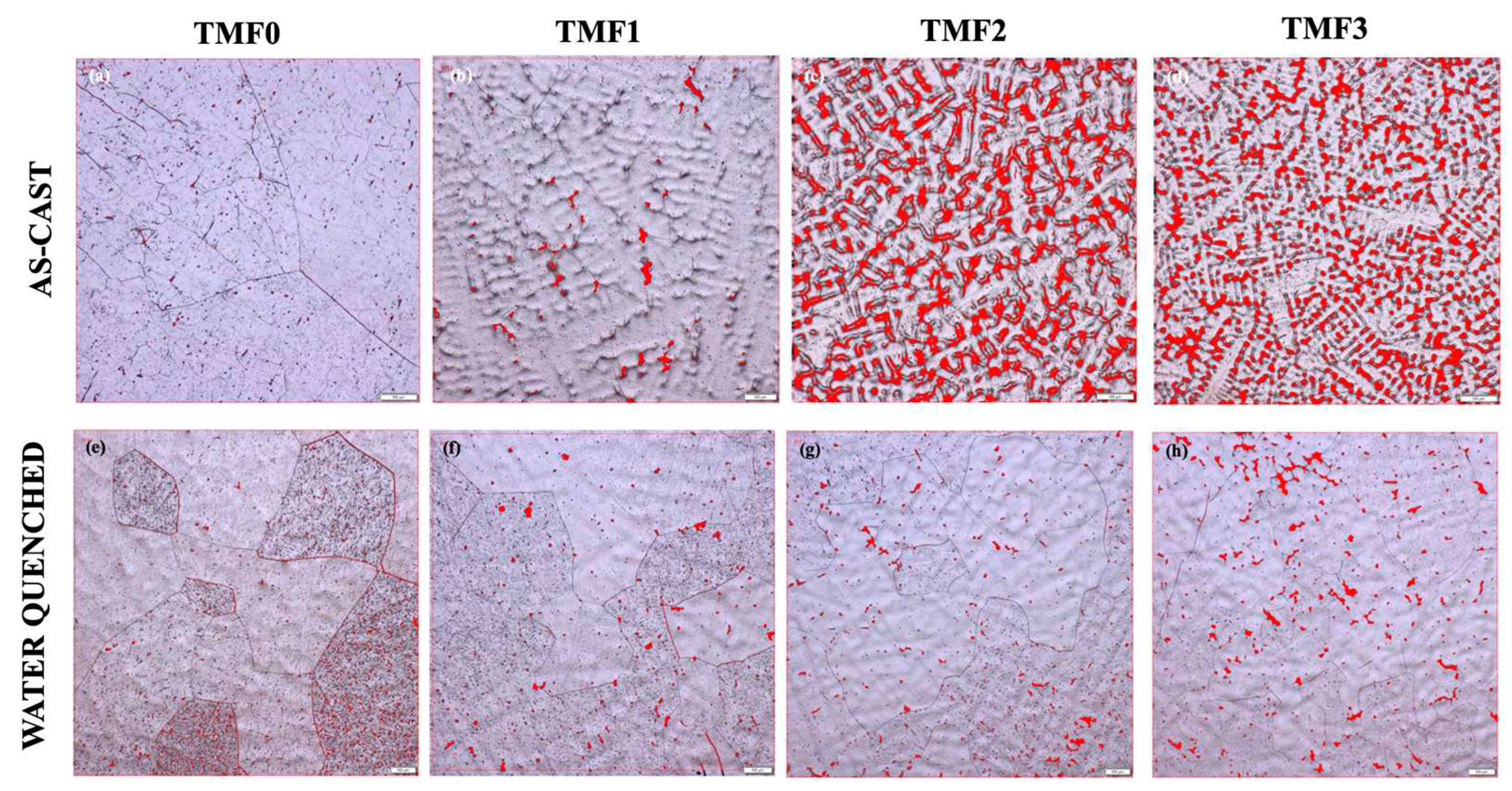
In order to quantify the amount of porosity that was analysed on the optical micrographs in Figure 1 above an Olympus software was used to measure the percentage porosity on the as-cast and quenched samples. Figure 2 illustrates the micrographs after porosity measurement, where the red dotted areas show where the porosity is located and subsequently where it was measured. The percentage porosity calculated in TMF0 sample in the as-cast condition was 0.29% and the porosity percentage on the quenched sample was calculated to be 0.85%, which is slightly higher than in the as-cast sample.
As shown in Figure 2a,e, the fraction of porosity in the as-cast condition of TMF0 alloy is much less compared to that in the quenched condition where pores are observed to have concentrated along the grain boundaries. The porosity measurement of TMF1 alloy in as-cast condition was 0.96% and it is slightly higher in the quenched sample (1.10%). Increasing the Fe content to 4 wt.% in TMF2 alloy led to significant increase in porosity percentage of 13.33% in the as-cast condition. As shown in Figure 2c, the porosity was mainly concentrated within the dendrites. Percentage porosity decreased significantly to 1.30% upon quenching. This change may be attributed to the absence of dendritic structures. Addition of 8 wt.% Fe (TMF3) led to the highest porosity percentage of 14.08% in the as-cast condition. Similarly, the porosity decreased significantly to 2.73% upon quenching. These porosity results illustrate that addition of higher Fe content yielded more pores as compared to a binary Ti-15Mo alloy. The underlying mechanism to this behaviour needs further attention.

3.3. Phase analysis

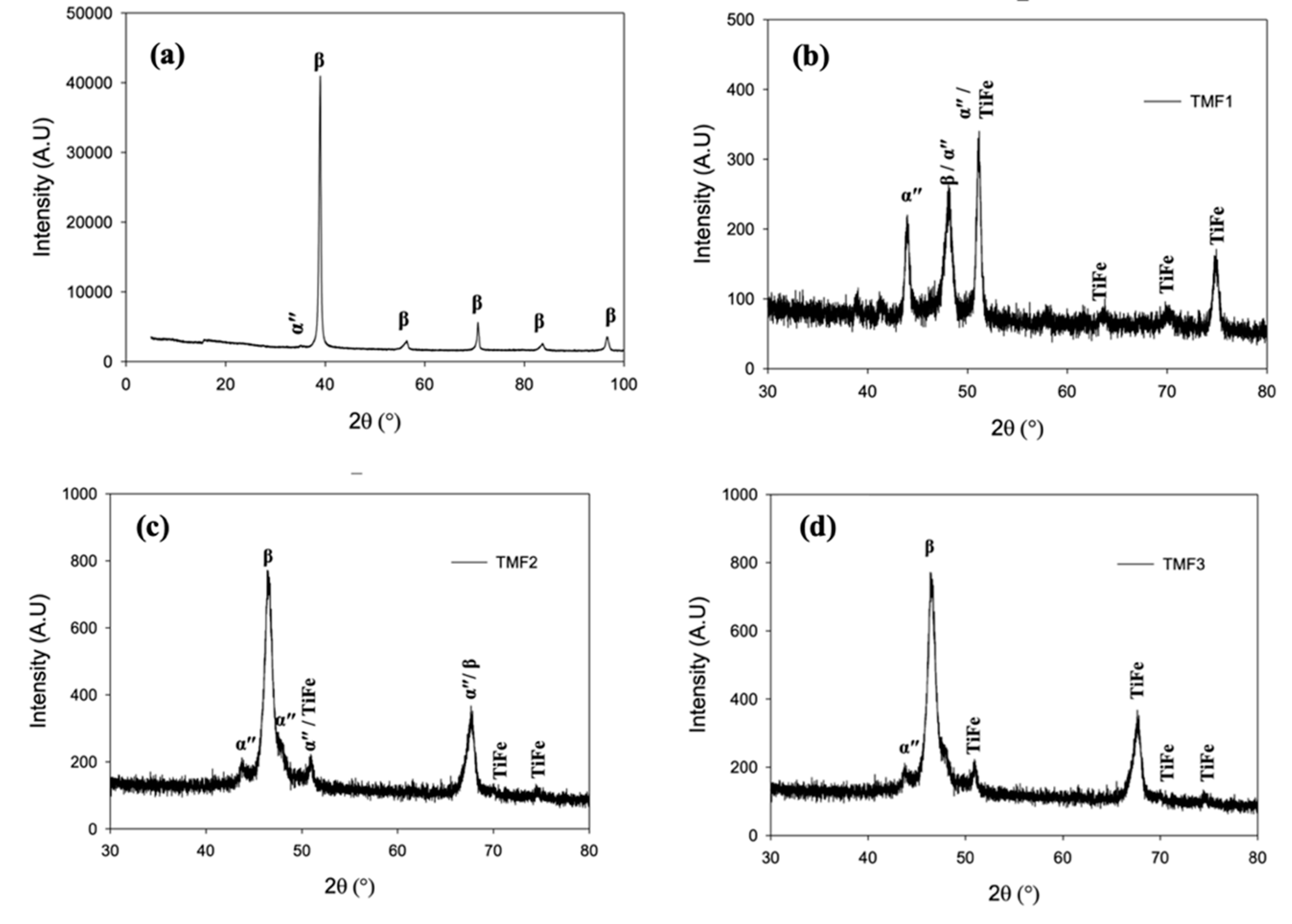
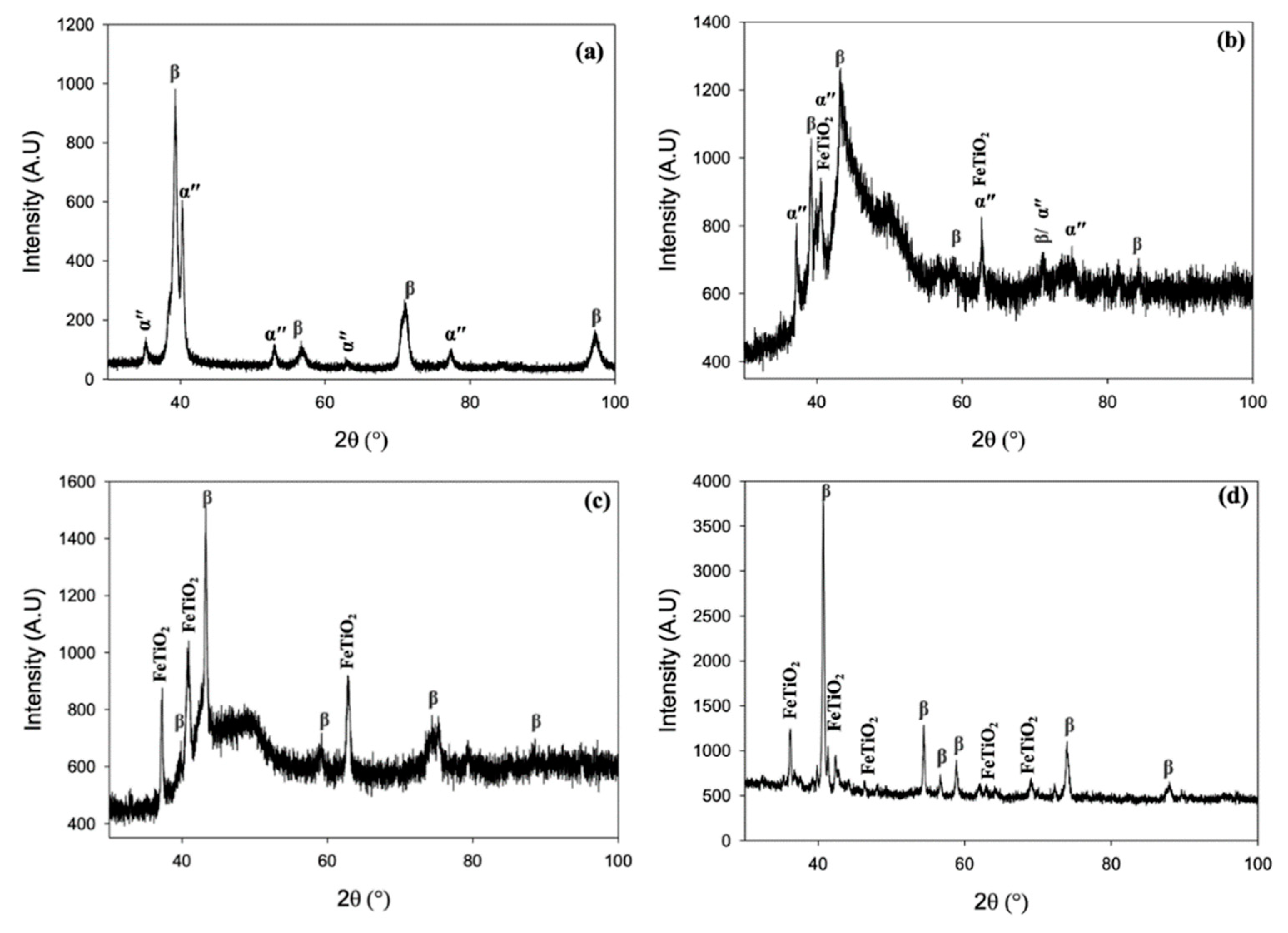
Presented in Figure 3 and Figure 4 are the XRD patterns of all considered alloys in the as-cast and quenched condition, respectively. The TMF0 in the as-cast condition show peaks belonging to both bcc (β) phase and orthorhombic martensitic α″ phase, as shown in Figure 3a. The quenched sample depicted peaks belonging to only bcc β phase peaks only as observed in Figure 4a. Presence of other metastable phases such omega and orthorhombic is not detected. Current results imply that the cooling rate experience by the sample when quenched from 1100°C into ice-brine was fast enough to retain complete (100%) β phase. This heat-treatment process did not afford any atomic displacement enough time to enable diffusionless martensitic transformation to occur. The addition of 4, 8 and 12wt.% Fe into Ti-15Mo, corresponding to TMF1 in Figure 3b, TMF2 in Figure 3c, and TMF3 in Figure 3d, respectively, the XRD patterns of the as-cast samples revealed peaks belonging to β, α″ and the ordered B2 intermetallic phase belonging to TiFe. Interestingly, the TMF1 alloy demonstrated the highest volume fraction of the intermetallic phase compared to TMF2 and TMF3 alloys. It also worth noting that the fraction of orthorhombic martensitic α″ phase decreased gradually with an increase in Fe content whereas the volume fraction of the intermetallic B2 phase increased. The presence of the orthorhombic martensitic α″ phase in TMF1, TMF2 and TMF3 showed that the cooling rate during melting was not sufficient to retain the β phase. At the same time, the presence of the intermetallic phase signified that this cooling rate was slow enough to allow formation and precipitation of B2 TiFe to occur from liquidus phase. It also worth noting that the addition of Fe resulted in a peak shift towards higher 2θ range. This peak shift can be attributed to lattice contraction due to smaller atomic radius of Fe.
The XRD results of quenched TMF1 sample shown in Figure 4b revealed peaks belonging to both the α″ and β phases as well as Ti-Fe mixed oxide (Fe·Ti·O2). On the other hand, the XRD results of quenched TMF2 and TMF3 shown in Figure 4c,d, respectively, depicted only peaks belonging to β and the Ti-Fe mixed oxides (Fe·Ti·O2) phases. The volume fraction of the mixed oxide phase increased with an increase in Fe content with the TMF3 sample detected to have the most significant amount. The presence of the metal oxides can be ascribed to air exposure when the sample was taken out of the furnace to the quenching bath. As a result of solution treatment, the presence of intermetallic B2 TiFe phase was not detected in the quenched samples. The disappearance of the TiFe phase in the quenched samples suggests that the solution treatment temperature of 1100°C was sufficient dissolve B2 TiFe since from the Ti-Fe binary phase diagram, the B2 TiFe only starts to dissolve into the β Ti(Fe) matrix at 1085°C. On contrary, it is also possible that the B2 phase contained some amount of Mo, which would increase the temperature where B2 phase dissolve into the β matrix to above 1100°C. This would render the B2 phase undissolved, thus suggesting the intermetallic phase to be more prone to oxidation than the β phase, responsible to forming mixed oxide. Therefore further analytical work is still necessary to understand the underlying mechanism. The XRD pattern of TMF0 in quenched condition is analogous to the results described by [25,26] in Ti-15Mo binary alloy. The presence of peaks belonging to the intermetallic B2 structure (TiFe) in the ternary alloys were comparable to XRD peaks reported by [27] in Ti65Fe35 binary alloy in as-cast condition and the TiFe was also reported by Li et al. in Ti-19Fe-5Sn-1Mo, Ti-17Fe-5Sn-3Mo and Ti-15Fe-5Sn-5Mo alloys. The presence of peaks of orthorhombic martensitic α″ phase in the ternary alloys in the as-cast condition were also reported in a ternary alloy Ti-7Ta-5Fe alloy reported by [28] and also in Ti-Zr-4Fe, and Ti-Zr-5Fe alloys investigated by [29].

3.4. Micro-Vickers Hardness

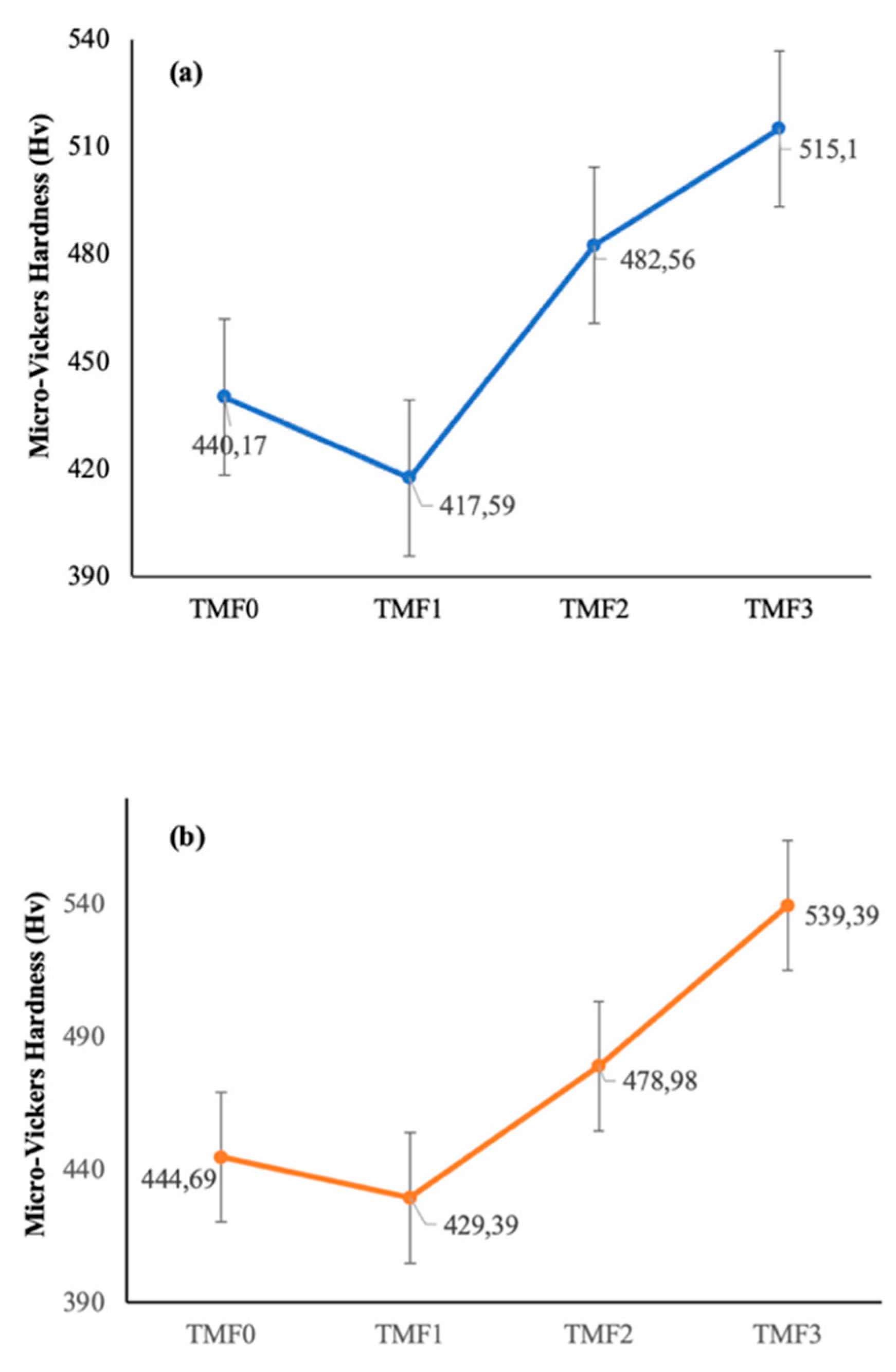
Hardness should be high enough to avoid shear failure during biomedical or refractory performance [30,31]. Figure 5 a and b presents hardness values of as-cast and quenched samples, respectively, which resulted in almost similar trends. The hardness of TMF0 was found to be 440,17 Hv0.5 in the as-cast condition, the hardness increased slightly to 444,69 Hv0.5 upon quenching. The addition of 4 wt.%, resulted in the hardness value of 417,59 Hv0.5 in the as-cast condition and its hardness increased to 429,39 Hv0.5 after quenching. A further increase in the Fe content to 8 wt.% yielded a hardness of 482,56 Hv0.5 in the as-cast condition but this hardness decreased slightly to 478,98 Hv0.5 when subjected to quenching. The TMF3 alloy with 12 wt.% Fe content was measured to have a hardness of 515,10 Hv0.5 in the as-cast condition. A significant increase in hardness to 539,39 Hv0.5 was observed upon quenching. The hardness of different Ti-alloy phases are summarized in the following increasing order H α″ < Hβ < H α < Hα’ < Hω according to Wu et al. The above trend entails that omega phase (ω) has the highest hardness, followed by HCP α’ phase which has a hardness value that is more than that of α phase. The β phase has hardness only higher than that of α″ phase. However, the following hardness trend reported by Lee at al [32] is slightly different Hω> Hα’ >Hα″ > Hβ >Hα. This trend implies that the hardness of α″ phase is higher than that of β phase whereas the α phase is the least hard. The hardness results reported in the current work research is in agreement with the hardness trend reported by [32]. Our observation is that the hardness of the quenched TMF0 alloy comprised of 100% β phase is higher than that in the as-cast condition. This higher hardness is mainly attributed to the finer grains as observed on the micrographs of the quenched sample in Figure 1f compared to that of the as-cast in Figure 1a. The increase in the hardness in TMF1 after quenching may be due to higher volume fraction of orthorhombic martensitic α″ phase compared to in the as-cast condition. High hardness of TMF2 in the as-cast condition could be due to several factors such as: the presence of high volume fraction of the brittle intermetallic B2 TiFe phase, the orthorhombic martensitic α″ phase as shown in the XRD patterns in Figure 3c, as well as a full dendritic structure observered in the OM micrographs in Figure 1c. In addition, high Fe content promotes solid solution strengthening effect. The slight decrease in the hardness after quenching may be attributed to the absence of α″ phase. It has been reported that the presence of porosity reduces the elastic modulus of a component, however, it can also lead to local stress concentrations which decrease the strength, hardness, and ductility of the alloys [Santos PF et al. 2016]. In comparison to the sample in the as-cast condition, a significant increase in hardness is observed in the TMF3 alloy upon quenching. Since the solid solution strengthening effect is common in both samples containing high Fe, it is highly possible that rapid oxidation of the intermetallic B2 phase could be responsible for increased hardness. It is for this reason that all the ternary samples were found to be very brittle, suggesting that the intermetallic B2 phase to be most prone to oxidation than the β matrix. The hardness of as-cast TMF0 alloy is found to be higher compared to those reported in [26] for Ti-15Mo alloy (307 HV0.2) and [26] for Ti-15Mo alloy (330 HV0.5) in the as-cast condition. The micro-Vickers hardness of the studied alloys was compared to other metastable alloys found in the literature. The TMF2 and TMF3 alloys were higher as compared to Ti-10Ta-4Fe (410Hv), Ti-12Nb-5Fe (293Hv), Ti-7Ta-5Fe (430Hv) alloys, while the TMF1 was lower than Ti-7Ta-5Fe alloy. The micro-Vickers hardness of the studied alloys was higher than the commercial materials such as Ti6Al4V (294 HV0.5) [34] and CP-Ti (156 HV0.2) reported by [26] and 210 HV0.5 in CP-Ti alloy [35].

3.5. Tensile Properties

Tensile properties were measured using the tensile tester machine. Tensile properties such as ultimate tensile, elastic modulus were recorded. The elastic modulus or stiffness should be as close as possible to that of the human bone to avoid stress shielding effect in orthopedic implants [30,31]. The gauged elastic modulus of Ti-15Mo-xFe alloys in the as-cast and quenched conditions are presented in Table 1 and Table 2, respectively, as a function of Fe content. As shown in these tables, the TMF0 alloy depicted an elastic modulus of 79 GPa in the as-cast condition while the elastic modulus upon quenching was measured to be 66 GPa. The Young’s modulus (E), which is an intrinsic materials property, depends on atomic bonding force amongst atoms and the bonding force is not only related to the crystal structure but also to the distances between atoms. Thus E can be affected by the atomic radius of the alloying element, heat treatment process and plastic deformation [36] and [37]. Any change in the distance between atoms of the material leads to variation in the atomic bonding force, and thus affect the resulting elastic modulus. The most common phenomenon is that a phase change caused by a heat treatment or stress may alter the elastic modulus of a metallic material because it changes the distance between atoms, which is why the different phases (crystal structures) have different elastic moduli [38]. Thus, the significant decrease in the elastic modulus of TMF0 after quenching may be attributed to the absence of the α″ phase which has higher elastic modulus than the β phase. Higher elastic modulus in the as-cast condition may be due to presence of the orthorhombic martensitic phase α″ as observered in the XRD patterns. It is widely reported that the β-Ti alloys which retains 100% β phase possess lower elastic modulus than those containing α, α’, α″ and ω phases [39]. This is in accordance with the elastic modulus trend reported by [40] which indicates β phase have the least elastic modulus.
Mechanical strength is vital property in structural applications or load bearing applications as it is required to maintain support. Similarly, the implants used under load need to possess much higher strength than the stress they will experience during service [41]. The measured ultimate tensile strength (UTS) of TMF0 in the as-cast condition is 264 MPa. However, upon quenching, this value almost doubled to 411 MPa. The elastic modulus of TMF1 alloy in the as-cast condition was measured to be 74 GPa which is 5 GPa lower than that of TMF0 alloy. The slight decrease in the elastic modulus is despite the presence of the hard and brittle B2 intermetallic phase. The UTS of TMF1, TMF2 and TMF3 in the as-cast and quenched conditions could not be measured due to the brittleness of the material, the samples crumbled or broke before they could reach a yield point. This high level of fragility is owed to the presence of most brittle B2 TiFe and its oxidised phases in the as-cast and quenched conditions, respectively. The tensile properties (UTS and elastic modulus) of TMF0 alloy in quenched condition are much lower than 594 MPa and 70.5 GPa, respectively, reported by [42]. The reason for this high modulus in studied alloy could be attributed by the presence of pores precipitated along the drain boundaries and inside the grains. The percentage porosity or the presence of pores were not reported by [42] in their published work. The tensile strength of the TMF0 alloy in the as-cast and quenched conditions was found to be significantly lower compared to the commercially used Ti6Al4V alloy (825-895MPa). Similarly, the elastic modulus of both TMF0 and TMF1 in the as-cast condition were lower than that of Ti6Al4V alloy (111GPa) [43]. The elastic modulus of TMF1 in the as-cast condition was even lower than that of Ti-12Nb-5Fe (90 GPa) [28], Ti-19Nb-2.5Fe (90GPa) [44] and Ti-30Nb-3Fe (81GPa) [45]. The above tensile results show that TMF0 in quenched condition shows better properties to be used as a potential alloy for the manufacturing of orthopedic implants, however the ternary alloys illustrated minimal possibility because of their brittleness that was attributed to the presence of intermetallic B2 phase in the as-cast condition or their resulting oxide upon heat treatment.

3.6. Fracture Surfaces

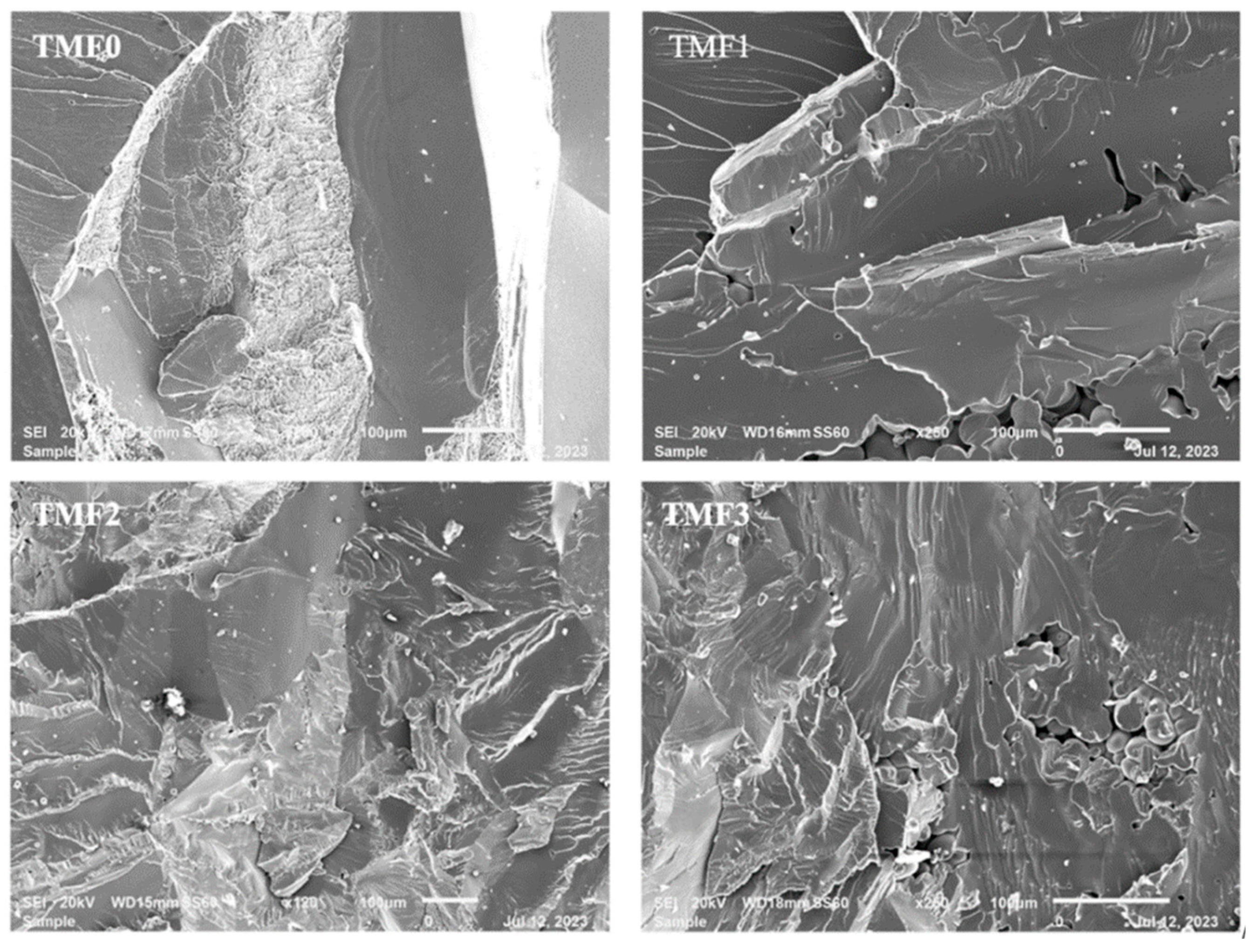
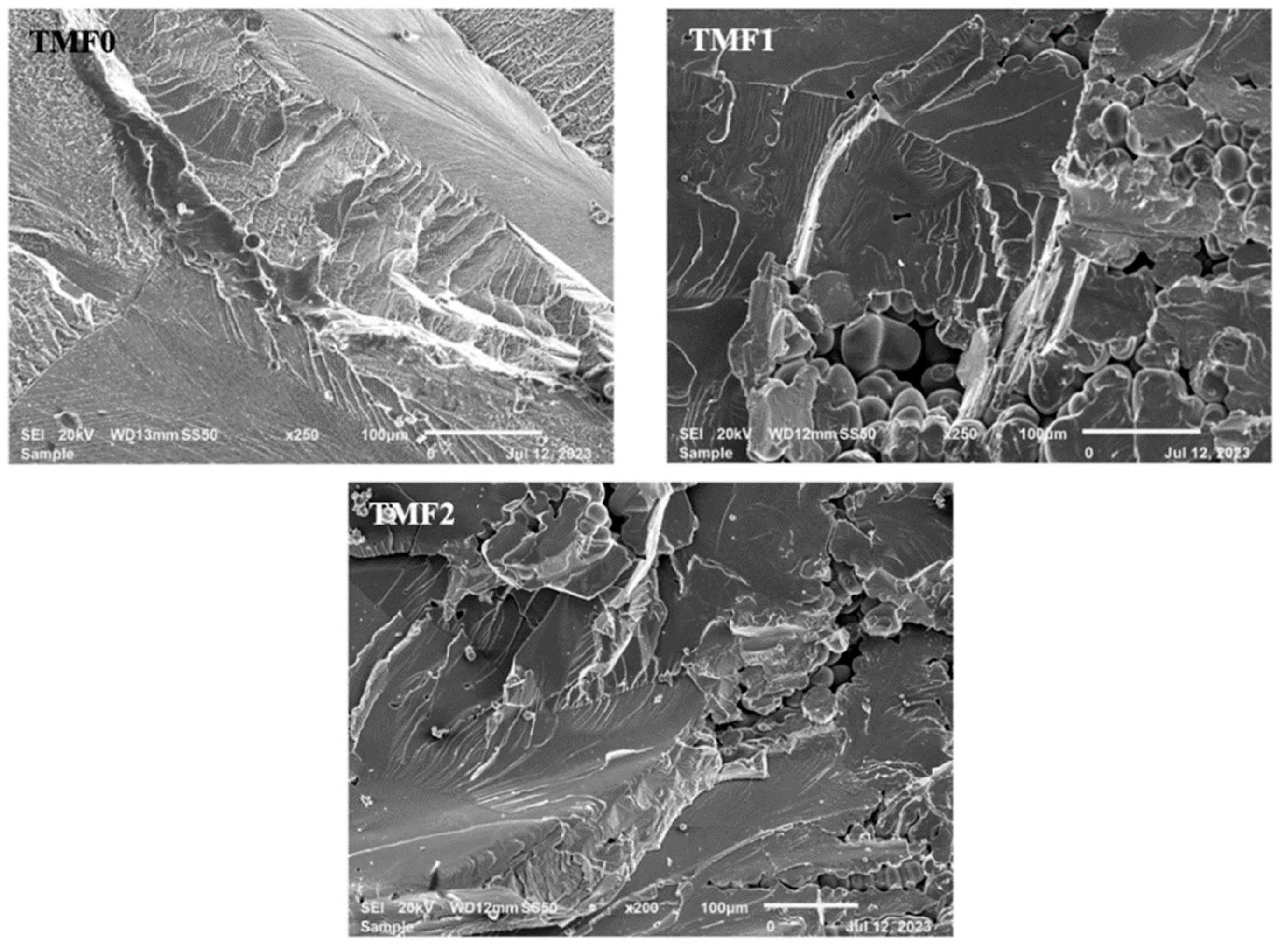
Fractography analysis of tensile specimens after tensile test were carried out on both the as-cast and quenched samples. SEM micrographs of fracture surfaces of tensile specimens are depicted in Figure 6 and Figure 7 for the samples in the as-cast and quenched conditions, respectively. As shown in Figure 6 and Figure 7, the TMF0 in the as-cast and quenched conditions exhibits both ductile and brittle fracture. The ductile fracture is characterized by dimple like fracture, while brittle fracture can be seen by cleavage fracture where river like patterns can be seen on the fracture surface. As shown in Figure 6, the fracture surfaces of TMF1, TMF2 and TMF3 samples in the as-cast condition comprises of only the brittle fracture. The same applies for TMF1 and TMF2 samples in the quenched condition, as shown in Figure 7. The micrographs were composed of river like patterns on the fracture surfaces, pores, cleavage facets and cracks that were growing along the fracture surfaces. The river like patterns, the cleavage facets and pores increased in fraction with an increase in the Fe content. The brittle fracture in the as-cast samples can be attributed to the precipitation of brittle intermetallic B2 TiFe phase as confirmed by the XRD analysis. On the other hand, the brittle fracture in the quenched samples is as a result of finely distributed brittle metal oxide formed from oxidation of intermetallic B2 phase. Moreover, it is reported in literature that a higher addition of a strengthening element leads to beta flecks or TiFe intermetallic that have adverse effects on the mechanical properties [15].

4. Conclusions

Microstructural characteristics, porosity evaluation, phase analysis, and tensile properties along with hardness results of the as-cast and quenched Ti-15Mo-xFe (x= 0,4,8,12wt%) alloys were systematically investigated for orthopedic applications. The following conclusions were drawn on the basis of the results of the study:
The OM micrographs of TMF0 in as cast condition demonstrated large equiaxed β structure and sub-structures of α″ phase, while the quenched sample was comprised of only finer equiaxed β grains. The micrographs of TMF1, TMF2 and TMF3 illustrated dendritic structure and pores in the as-cast condition whereas micrographs of their quenched samples depicted only large equiaxed grains of β without the dendrites.
The XRD analysis conformed that TMF0 in as-cast condition comprised of both bcc β and orthorhombic martensitic α″ phases, whereas the quenched alloy was composed of only β phase. TMF1, TMF2, TMF3 in as-cast condition encompassed the formation of an intermetallic phase of TiFe and their quenched alloys were contained the β phase, α″ phase, and a mixed oxide layer.
The porosity measurements revealed a slight increase in the porosity in TMF0 and TMF1 upon quenching, and a significant increase in porosity in TMF2 and TMF3 alloys.
The Micro-Hardness of the studied alloys showed similar trend in both as-cast and quenched conditions, where the hardness increased slightly in quenched samples.
The elastic modulus of TMF0 decreased drastically after quenching. Comparing the elastic modulus of TMF0 and TMF1 in as-cast condition, the TMF1 showed the lowest modulus as compared to TMF0. Most tensile properties of TMF2, and TMF3 in as-cast and quenching conditions could not be determined due to the fragility of the samples.
The fracture surfaces of TMF0 exhibited both ductile and brittle fracture in as-cast and quenched conditions whereas the only brittle fracture mode was observed in the TMF1, TMF2 and TMF3 alloys in both conditions.
In summary, a concept of evaluating the effect of high addition of Fe content on Ti-15Mo alloy for orthopedic application was realised. It was discovered that the higher the content of Fe into Ti-15Mo alloy results in a formation of a brittle intermetallic B2 TiFe phase which negatively affect the mechanical properties. The tensile properties of alloys with high content of Fe could not be recorded due to the fragility of the samples. Thus the studied ternary alloys cannot be considered ideal for orthopedic application due to the high

Author Contributions

Nthabiseng Moshokoa: Conceptualization of the manuscript. Nthabiseng Moshokoa, Maje Phasha: Methodology. Nthabiseng Moshokoa: Original draft preparation: Nthabiseng Moshokoa, Maje Phasha, Washington Makoana, Lerato Raganya and Elizabeth Makhatha: Software and Resources. Moshokoa Nthabiseng and Maje Phasha: Validation, Formal Analysis, Investigation, Data curation, Reviewing and editing. Maje Phasha, Elizabeth Makhatha, Lerato Raganya, Hasani Chauke and Diale Ramogohlo: Supervision. Elizabeth Makhatha and Maje Phasha: Funding acquisition. The funders had a role in the design of the study, collection of data, interpretation and analyses of data, in editing the manuscript and in the decision to publish the results.

Funding

We can declare that this research received no external funding.

Data Availability Statement

The data that support the findings of this study are available from the corresponding author (Moshokoa Nthabiseng and Maje Phasha) upon request.

Acknowledgments

This work was supported and funded by Mintek (Advanced Metallurgy Division), and the studies were funded by CSIR-IBS. The author would like to acknowledge Mintek (AMD) and CSIR (AME and National Laser Center) for providing access to their laboratories. NM is grateful to the technical assistance provided by Mintek staff (Mr. Mbavhalelo Maumela, Mr. Absalom Mabeba, and Mr. Andrew Mampuru) as well as Mr. Joseph Moema for his support.

Conflicts of Interest

The author declare no conflicts of interest.

References

  1. M. Niinomi and M. Nakai, “Titanium-based biomaterials for preventing stress shielding between implant devices and bone,” International Journal of Biomaterials. 2011. [CrossRef]
  2. Niinomi,M; Nakai, M.; and Hieda,J. “Development of new metallic alloys for biomedical applications,” Acta Biomaterialia, vol. 8, no. 11. Elsevier Ltd., 2012. pp. 3888–3903. [CrossRef]
  3. Biesiekierski, A.; Wang, J.; and Wen, C. “A brief review of biomedical Shape Memory Alloys by powder metallurgy,” in Key Engineering Materials, Trans Tech Publications Ltd., 2012. pp. 195–200. [CrossRef]
  4. Bazaka, O.; Bazaka, K.; Kingshott, P.; Crawford, RJ.; and Ivanova, EP. “Metallic Implants for Biomedical Applications.” [Online]. Available: http://books.rsc.org/books/edited-volume/chapter-pdf/1609069/bk9781788017534-00001.pdf.
  5. Akahori, T.; Niinomi, M.; Fukui, H.; Ogawa, M.; and Toda, H. “Improvement in fatigue characteristics of newly developed beta type titanium alloy for biomedical applications by thermo-mechanical treatments,” in Materials Science and Engineering C, May 2005. pp. 248–254. [CrossRef]
  6. Niinomi, M. “Recent research and development in titanium alloys for biomedical applications and healthcare goods,” Science and Technology of Advanced Materials, vol. 4, no. 5. pp. 445–454, Sep. 2003. [CrossRef]
  7. Williams, DF. “On the mechanisms of biocompatibility,” Biomaterials, vol. 29, no. 20, Jul. 2008. pp. 2941–2953. [CrossRef]
  8. Niinomi, M. “Mechanical biocompatibilities of titanium alloys for biomedical applications,” Journal of the Mechanical Behavior of Biomedical Materials, vol. 1, no. 1. Jan. 2008. pp. 30–42. [CrossRef]
  9. Mishra, F,T. “Mechanical and Tribological Properties and Biocompatibility of Diffusion Hardened Ti-13Nb-13Zr — A New Titanium Alloy for Surgical Implants,” In Medical applications of titanium and its alloys: the material and biological issues. ASTM International, Jan. 1996. pp. 96–113. [CrossRef]
  10. Wang, K.; Gustavson, L.; and Dumbleton, J. “Microstructure and Properties of a New Beta Titanium Alloy, Ti-12Mo-6Zr-2Fe, Developed for Surgical Implants,”. Jan. 1996. pp. 76–87. [CrossRef]
  11. Zardiackas, L.; Mitchell, D.; and Disegi, J. “Characterization of Ti-15Mo Beta Titanium Alloy for Orthopaedic Implant Applications,” Jan. 1996. pp. 60–75. [CrossRef]
  12. Gepreel, M.; Hefnawy, A.; Hussein, A.; and Kandil, S. “Effect of heat treatment on the microstructure of Ti-Nb-Ta base alloys for biomedical applications,” International Journal of Chemical and Applied Biological Sciences, vol. 1, no. 6, 2014. p. 119. [CrossRef]
  13. Kasuga,T.; Nogami,M.; Niinomi, M.; Hattori, T. “Bioactive calcium phosphate invert glass-ceramic coating on b-type Ti-29Nb-13Ta-4.6Zr alloy,” 2003. [CrossRef]
  14. Bolzoni, L.“Low-cost Fe-bearing powder metallurgy Ti alloys,” Metal Powder Report, vol. 74, no. 6, Nov. 2019. pp. 308–313. [CrossRef]
  15. Mitchell, A.; Kawakami, A.; and Cockcroft, S.L. “Beta Fleck and Segregation in Titanium Alloy Ingots.” 2006. [CrossRef]
  16. Devaraj A.; et al., “A low-cost hierarchical nanostructured beta-titanium alloy with high strength,” Nat Commun, vol. 7, Apr. 2016. [CrossRef]
  17. Ji, X.; Emura, S.; Min, X.; and Tsuchiya, K. “Strain-rate effect on work-hardening behavior in β-type Ti-10Mo-1Fe alloy with TWIP effect,” Materials Science and Engineering A, vol. 707, Nov. 2017. pp. 701–707. [CrossRef]
  18. Bao, Y.et al., “High strength, low modulus and biocompatible porous Ti–Mo–Fe alloys,” Journal of Porous Materials, vol. 21, no. 6, Nov. 2014. pp. 913–919. [CrossRef]
  19. Song, B.; Chen, Y.; Xiao, W., Zhou, L.; and Ma, C. “Formation of intermediate phases and their influences on the microstructure of high strength near-β titanium alloy,” Materials Science and Engineering: A, vol. 793, Aug. 2020. [CrossRef]
  20. Ruan,Y.; Mohajerani, A.; and Dao,M. “Microstructural and Mechanical-Property Manipulation through Rapid Dendrite Growth and Undercooling in an Fe-based Multinary Alloy,” Sci Rep, vol. 6, Aug. 2016. [CrossRef]
  21. Antoniac, V.; Saha, S.; and Roy, S.“materials Metallic Dental Implants Wear Mechanisms, Materials, and Manufacturing Processes: A Literature Review,” 2022. [CrossRef]
  22. Razavykia,A.; Brusa,E.; Delprete,C.; and Yavari, R. “materials An Overview of Additive Manufacturing Technologies-A Review to Technical Synthesis in Numerical Study of Selective Laser Melting”. [CrossRef]
  23. Elshaer, R.N.; and Ibrahim,K.M. “Study of Microstructure, Mechanical Properties, and Corrosion Behavior of As-Cast Ni-Ti and Ti-6Al-4V Alloys,” J Mater Eng Perform, 2022. [CrossRef]
  24. Okulov, I.V. et al., “Effect of microstructure on the mechanical properties of as-cast Ti-Nb-Al-Cu-Ni alloys for biomedical application,” Materials Science and Engineering C, vol. 33, no. 8, Dec. 2013. pp. 4795–4801. [CrossRef]
  25. Moshokoa, N.A.; Raganya, M.L.; Machaka, R.; Makhatha, M.E.; and Obadele, B.A. “The effect of molybdenum content on the microstructural evolution and tensile properties of as-cast Ti-Mo alloys,” Mater Today Commun, vol. 27, Jun. 2021. [CrossRef]
  26. Ho, W.; Ju, C.; and Chern Lin, J. “Structure and properties of cast binary Ti–Mo alloys,” 1999. [CrossRef]
  27. Louzguine,D.V.; Kato, H.; Louzguina,L.V.; and Inoue, A. “High-strength binary Ti-Fe bulk alloys with enhanced ductility,” J Mater Res, vol. 19, no. 12, Dec. 2004. pp. 3600–3606. [CrossRef]
  28. Biesiekierski, A.; Lin, J.; Li, Y.; Ping,D.; Yamabe-Mitarai, Y.; and Wen, C. “Investigations into Ti-(Nb,Ta)-Fe alloys for biomedical applications,” Acta Biomater, vol. 32, Mar. 2016. pp. 336–347. [CrossRef]
  29. Qi, P.; Li, B.; Wang, T.; Zhou, L.; and Nie, Z. “Microstructure and properties of a novel ternary Ti–6Zr–xFe alloy for biomedical applications,” J Alloys Compd, vol. 854, Feb. 2021. [CrossRef]
  30. Guo, L. et al., “On the design evolution of hip implants: A review,” Materials and Design, vol. 216. Elsevier Ltd., Apr. 01, 2022. [CrossRef]
  31. Cui, Y.W.et al., “Metastable pitting corrosion behavior and characteristics of passive film of laser powder bed fusion produced Ti–6Al–4V in NaCl solutions with different concentrations,” Corros Sci, vol. 215, May 2023. [CrossRef]
  32. Lee, C. M.; Ju, C.P.; and Chern Lin, J.H. “Structure-property relationship of cast Ti-Nb alloys,” J Oral Rehabil, vol. 29, no. 4, pp. 314–322, Apr. 2002. [CrossRef]
  33. Santos, P.F. et al., “Fabrication of low-cost beta-type Ti-Mn alloys for biomedical applications by metal injection molding process and their mechanical properties,” J Mech Behav Biomed Mater, vol. 59, Jun. 2016. pp. 497–507. [CrossRef]
  34. Chen, L.Y.; Cui, Y.W.; and Zhang, L.C. “Recent development in beta titanium alloys for biomedical applications,” Metals (Basel), vol. 10, no. 9, Sep. 2020. pp. 1–29. [CrossRef]
  35. Severino Martins, J.R.; and Grandini, C.R. “Structural characterization of Ti-15Mo alloy used as biomaterial by Rietveld method,” J Appl Phys, vol. 111, no. 8, Apr. 2012. [CrossRef]
  36. Zhou, Y. L.; Niinomi, M.; and Akahori, T. “Effects of Ta content on Young’s modulus and tensile properties of binary Ti-Ta alloys for biomedical applications,” Materials Science and Engineering: A, vol. 371, no. 1–2, Apr. 2004. pp. 283–290. [CrossRef]
  37. Lee, Y.T.; and Welsch, G. “Young’s Modulus and Damping of Ti-6AI-4V Alloy as a Function of Heat Treatment and Oxygen Concentration,” 1990. [CrossRef]
  38. Dieter, G.E and Bacon D, Mechanical Metallurgy, vol. 3. New York, 1976.
  39. Mohan, P.; Rajak, D.K.; Pruncu, C.I.; Behera,A.; Amigó-Borrás, V.; and Elshalakany, A.B.“Influence of β-phase stability in elemental blended Ti-Mo and Ti-Mo-Zr alloys,” Micron, vol. 142, Mar. 2021. [CrossRef]
  40. Hao, Y.L. et al., “Young’s Modulus and Mechanical Properties of Ti-29Nb-13Ta- 4.6Zr in Relation to a9 Martensite.”. [CrossRef]
  41. Jung, H. S.; Lee, T.; Kwon, I.K.; Kim, H. S.; Hahn, S.K.; and Lee, C.S. “Surface modification of multipass caliber-rolled ti alloy with dexamethasone-loaded graphene for dental applications,” ACS Appl Mater Interfaces, vol. 7, no. 18, May 2015. pp. 9598–9607. [CrossRef]
  42. Moshokoa, N.; Raganya, L.; Obadele, B.A.; Machaka, R.; and Makhatha, M.E. “Microstructural and mechanical properties of Ti-Mo alloys designed by the cluster plus glue atom model for biomedical application,” International Journal of Advanced Manufacturing Technology, vol. 111, no. 5–6, Nov. 2020. pp. 1237–1246. [CrossRef]
  43. Niinomi, M. “Mechanical properties of biomedical titanium alloys,” 1998. [CrossRef]
  44. Salvador, C. A. F.; Dal Bó, M. R F.; Costa, H.; M. Taipina, O.; Lopes, E. S. N.; and Caram, R. “Solute lean Ti-Nb-Fe alloys: An exploratory study,” J Mech Behav Biomed Mater, vol. 65, Jan. 2017. pp. 761–769. [CrossRef]
  45. Lopes, E.S.N.; C. A. F. Salvador, C.A.F.; D. R. Andrade, D.R.; A. Cremasco, A.; K. N. Campo, K. N.; and Caram, R. “Microstructure, Mechanical Properties, and Electrochemical Behavior of Ti-Nb-Fe Alloys Applied as Biomaterials,” Metall Mater Trans A Phys Metall Mater Sci, vol. 47, no. 6, Jun. 2016. pp. 3213–3226. [CrossRef]
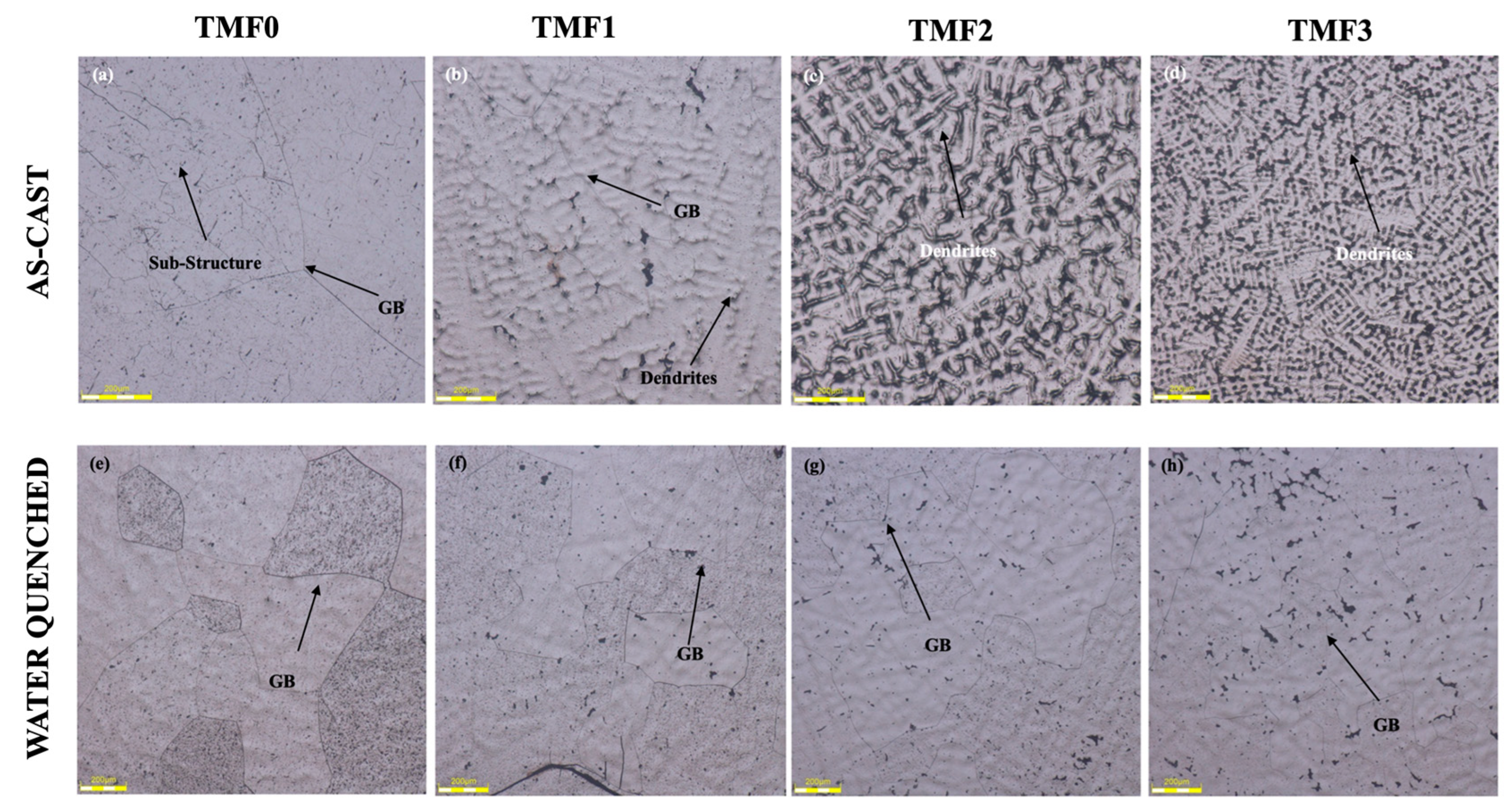
Figure 1. Optical Micrographs of as-cast (a) TMF0, (b) TMF1, (c) TMF2 and (d) TMF3 and those of quenched (e) TMF0, (f) TMF1, (g) TMF2 and (h) TMF3 alloys.
Preprints 97114 g001
Figure 2. Porosity Measurement of as-cast (a) TMF0, (b) TMF1, (c) TMF2 and (d) TMF3 alloys and the quenched (e) TMF0, (f) TMF1, (g) TMF2 and (h) TMF3 alloys.
Preprints 97114 g002
Figure 3. XRD results of as-cast, (a) TMF0 (b) TMF1, (c) TMF2 and (d) TMF3 alloys.
Preprints 97114 g003
Figure 4. XRD results of quenched (a) TMF0, (b) TMF1, (c) TMF2 and (d) TMF3 alloys.
Preprints 97114 g004
Figure 5. Micro-Vickers Hardness of (a) as-cast and (b) quenched TMF alloys.
Preprints 97114 g005
Figure 6. Fracture surface of as-cast alloys after tensile test.
Preprints 97114 g006
Figure 7. Fracture surface of quenched alloys.
Preprints 97114 g007
Table 1. Tensile properties of as-cast TMF alloys.
Alloy Name UTS (MPa) E (GPa) Reference
TMF0 264 79 This study
TMF1 - 74 This study
TMF2 - -
TMF3 - -
Table 2. Tensile Properties of quenched TMF alloys.
Alloy Name UTS (MPa) E (GPa) Reference
TMF0 411 66 This study
TMF1 - -
TMF2 - -
TMF3 - -
Disclaimer/Publisher’s Note: The statements, opinions and data contained in all publications are solely those of the individual author(s) and contributor(s) and not of MDPI and/or the editor(s). MDPI and/or the editor(s) disclaim responsibility for any injury to people or property resulting from any ideas, methods, instructions or products referred to in the content.
Copyright: This open access article is published under a Creative Commons CC BY 4.0 license, which permit the free download, distribution, and reuse, provided that the author and preprint are cited in any reuse.
Alerts
Prerpints.org logo

Preprints.org is a free preprint server supported by MDPI in Basel, Switzerland.

Subscribe

© 2025 MDPI (Basel, Switzerland) unless otherwise stated