1. Introduction
Manufacturing, which plays a vital role in the growth of the economy, has contributed to an estimated 24 % of the U.S. Gross Domestic Product [
1]. In addition, manufacturing has the largest economic multiplier of 3.05, i.e., each
$1 of manufacturing output generates
$3.05 in total economic activity [
2]. As the final step in the manufacturing chain, machining claims up to 65% of all manufacturing processes, providing the required dimensional accuracy, surface quality and other quality attributes. The cost associated with machining can exceed 65% of the product cost. This explains the adoption of advanced manufacturing technologies as a priority for government science and technology strategies [
3]. The recognition of the potential conflict between the economic growth and the protection of the environment, which is a natural capital (a source, and a sink) led to the need to put an end to economic growth in order to protect the environment, as presented in the “Limits to Growth” Report [
4], published in 1972. Later this view was changed, and it became clear that there is a need to revive economic growth globally as outlined in the so-called Brundtland Report [
5], which considered the environment and development as a single issue, introducing the concept of “sustainable development” (SD). Transformation of the economic growth-environment protection conflict into opportunities was one of the main drives for the industrial revolutions [
6]. The fourth Industrial revolution (I4.0) represents a transformative paradigm in manufacturing, characterized by the integration of cutting-edge technologies to create smart, interconnected, and highly automated industrial systems. I4.0 aims to harnesses the power of cyber-physical systems, the Internet of Things (IoT), artificial intelligence, big data analytics, and advanced robotics to revolutionize the way products are designed, produced, and delivered. The seamless exchange of data across the entire value chain in I4.0 enables real-time decision-making, predictive maintenance, and unparalleled efficiency gains, leading to intelligent, self-optimizing production processes. As recently as 2015, the fifth industrial revolution (I5.0) was introduced to overcome the shortfalls of its predecessor I4.0, which lacks key design and performance dimensions [
7]. Although I4.0 and I5.0 share basic considerations of digital transformation, customization of products, sustainable processes, and creation of digital twins, the manufacturing paradigm I5.0 addresses other goals that include the possible customization of manufacturing processes, human-AI collaboration, and cognitive cyber physical systems [
8]. Additionally, I5.0 addressed the question of sustainability strategy, side by side with the resilience strategy [
6,
7]. With this new vision, I5.0 paradigm shift sets the ground for a framework that integrates high performance manufacturing and sustainability [
9].
The three pillars of I5.0 are resilience, sustainability, and human-centricity. The resilience strategy requires interdisciplinary technologies that support creating cognitive cyber-physical systems (CCPS) to blend physical components and computing devices and to enable machine learning (ML) and artificial intelligence (AI) based solutions to perform its functionality of monitoring, control, and automation of physical processes, mimicking human-like cognitive processes, such as perception, reasoning, learning, decision-making, communication, and collaboration [
10]. For machining processes, other technologies that are needed include: (1) real-time process and tool condition monitoring (TCM); wear and sudden tool pre-failure detection using advanced AI and deep machine learning (DL) techniques [
11], and wireless sensor-based smart tooling [
12]. The data-driven training of the TCM system needs to advance to account for the variability of the signal features due to the physical phenomena that take place during the cutting of various classes of materials, e.g., metal matrix composites, biomaterials, and additively manufactured parts; (2) Offline-online optimization and adaptive machining. This technology, which can easily be incorporated in a CCPS platform, was shown to improve productivity by up to 45%, and when integrated with a TCM, the production cost can be reduced by up to 25% [
13]; and (3) physics-based constitutive models for anisotropic, and graded materials that need to be developed and combined with artificial intelligence (AI) and swarm intelligent (SI) techniques to improve CCPS’ adaptability, and scalability.
Process optimization is an essential element of the modern manufacturing industry and a key element of the industrial revolutions paradigm that can provide considerable improvements in terms of process productivity and product quality. Traditionally, machining parameters have been determined based on the experience of the machine tool operators, or through an experimental procedure. To mitigate the risk of catastrophic events, machining conditions are often chosen conservatively, albeit at the expense of limiting process productivity and increasing the environmental impact. In pursuit of more precise machining parameters, various process optimization methodologies have been developed. Improving process productivity has been the main objective for machining process optimization in today’s competitive manufacturing industry. This can be achieved by reducing the cutting time and using the full potential of the cutting capacity of the machine tools. While the process productivity objective is commonly considered in optimizing roughing operations, the quality of the machined part is usually the main objective for the finishing operations [
14]. The two main approaches to maximize process productivity are force/power-based optimization, and material removal rate (MRR)-based optimization [
15]. The force/power-based optimization provides better performance than the MRR-based approach [
16]. However, the implementation of the MRR-based approach is more feasible in industrial applications due to the complexity of the calculation of the uncut chip thickness and cutting forces, especially for free-form surfaces, in a force/power-based optimization approach [
16,
17].
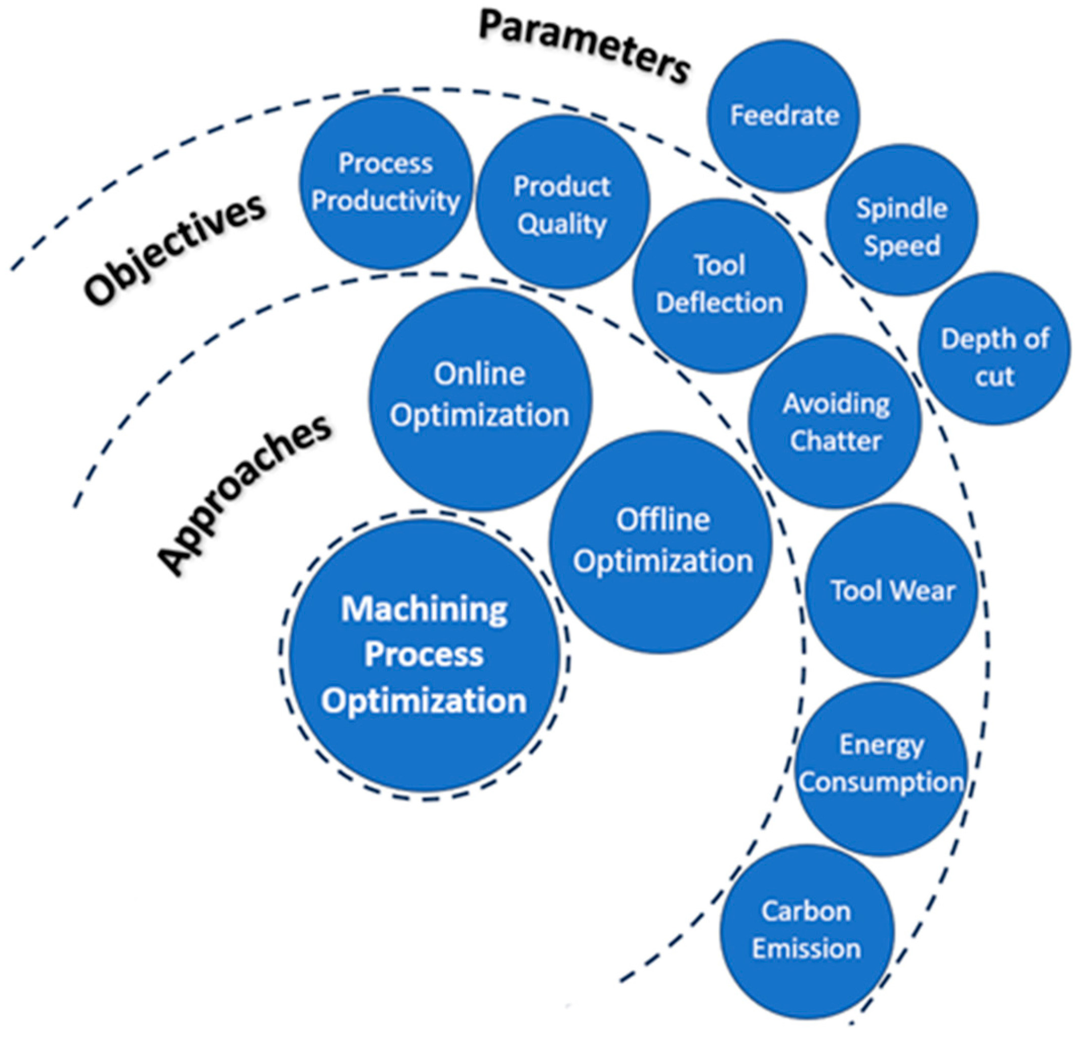
Process optimization methodologies can be categorized into two main approaches: offline process optimization and online process optimization [
18,
19]. In offline process optimization, a model is required to estimate one or multiple machining states based on the machining parameters. Analytical, numerical, and empirical approaches were used to model the cutting operation. The output of the cutting model, directly or indirectly, is used to estimate machining objective functions such as process productivity [
14,
17,
20,
21,
22], machined part quality [
23,
24,
25,
26,
27], production cost [
28,
29,
30,
31,
32], tool wear rate [
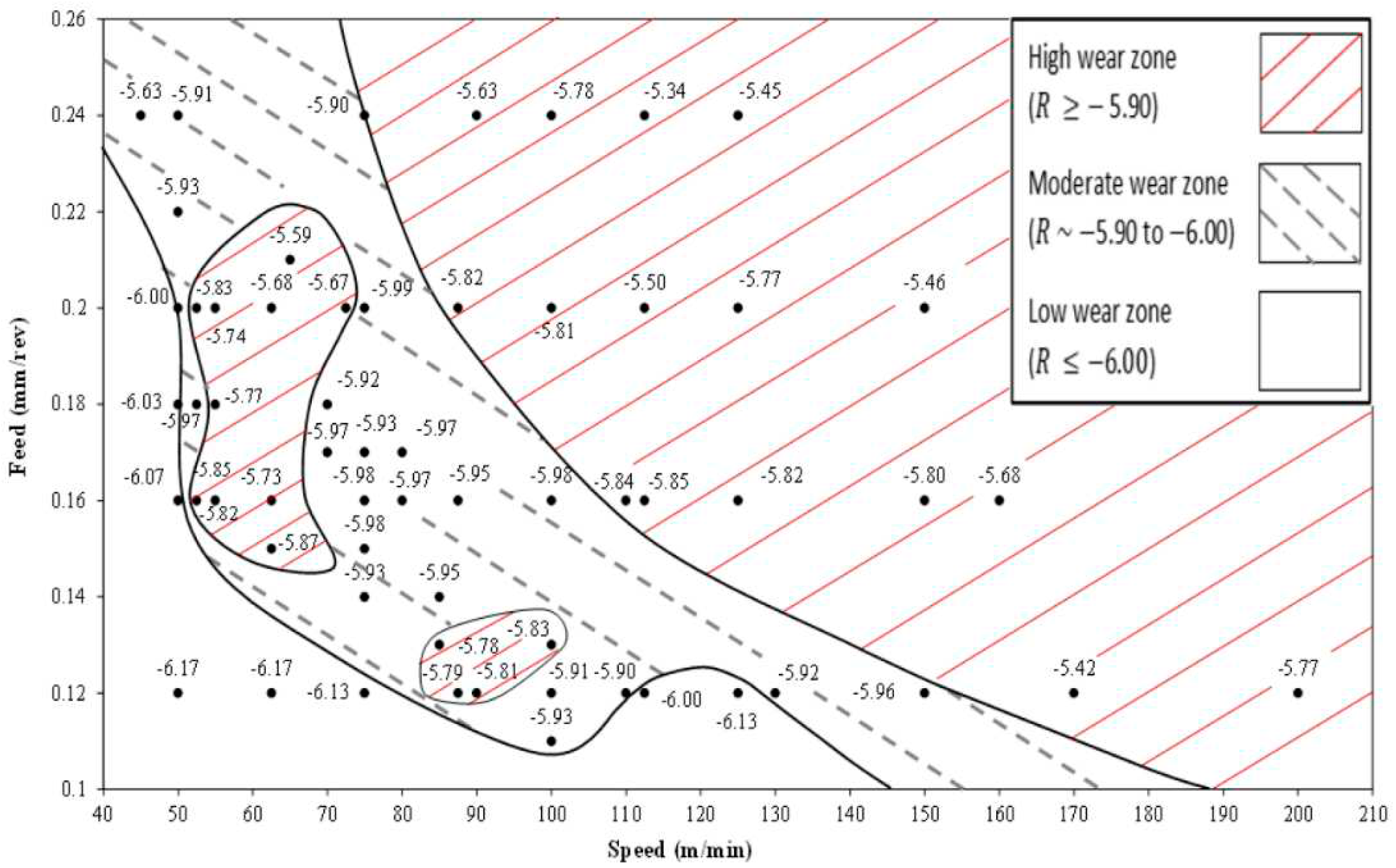
33,
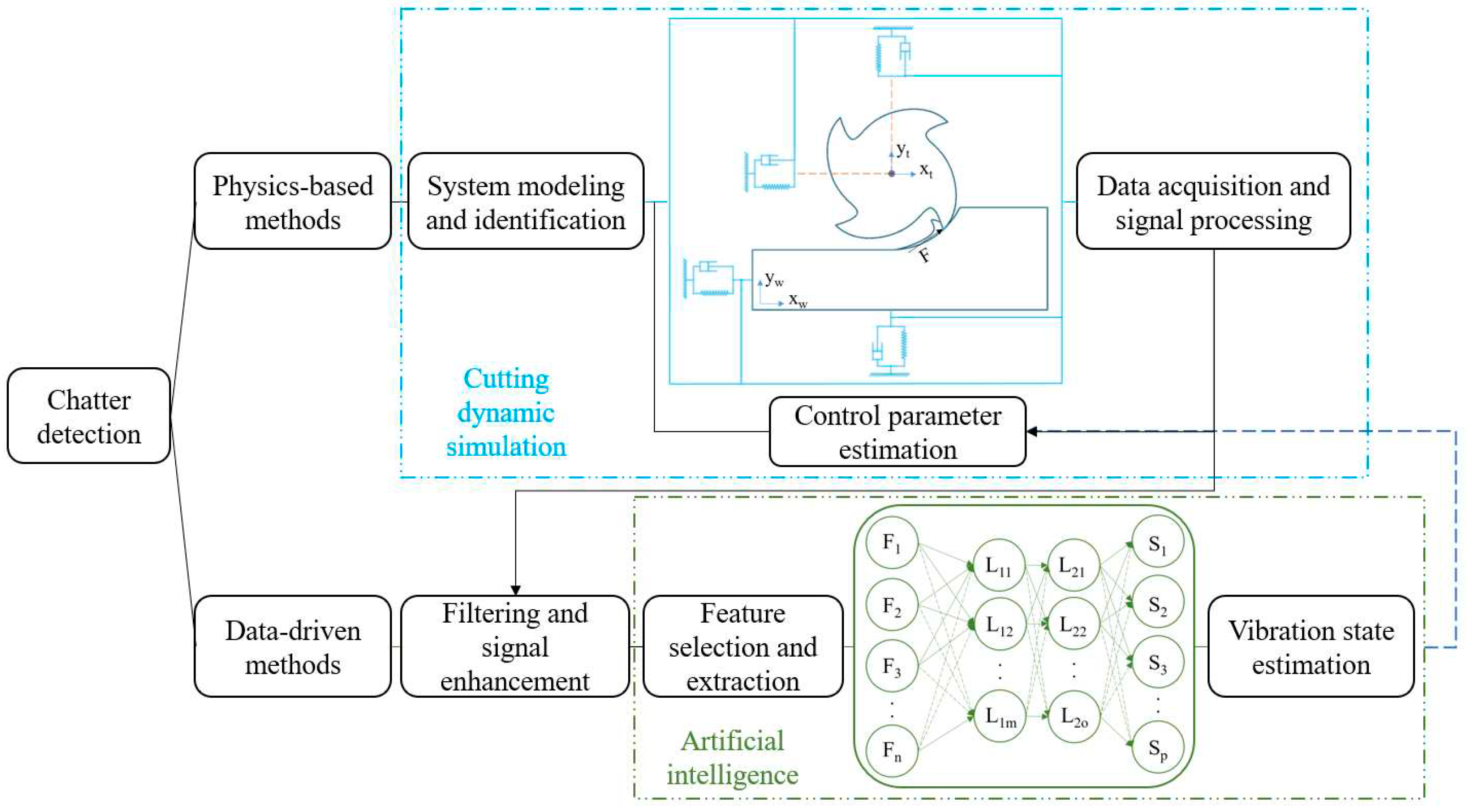
34], chatter stability thresholds [
35,
36], energy consumption [
37,
38,
39] and carbon emission [
40,
41,
42]. Online process optimization is defined as a numerical control process in which the machining parameters are regulated based on time-varying feedback [
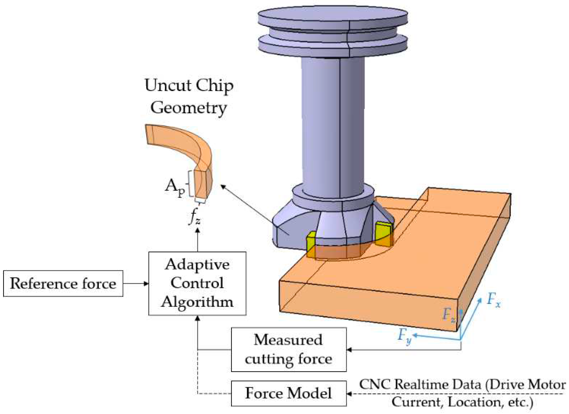
43]. The online optimization module is commonly implemented as a constrained optimization to regulate the cutting parameters such as feedrate or spindle speed. This approach is designed to either limit or achieve consistency in key factors such as cutting force/power, tool wear rate, tool deflection, or their combined effects. The status of the constraints can be estimated directly from feedback signals such as the driving motor current, the cutting zone temperature, or acoustic emission (AE) signals. Alternatively, predictive information can be derived through analytical or statistical modeling approaches. An online optimization system can deal with the disturbances caused by the wide range of variations in the machining conditions. Implementation of an online control system can be highly beneficial to avoid deteriorating conditions such as chatter and excessive tool wear rate. In addition, the online optimization system mitigates fluctuations in cutting states, thereby reducing the likelihood of sudden tool breakage [
44]. The main drawbacks of implementing an online optimization system are the high cost of sensing, data acquisition, and processing equipment, as well as the difficulty of mounting sensors close to the cutting zone, and the sensor sensitivity to harsh cutting environments [
19]. Furthermore, achieving reliability and comprehensiveness in online process optimization systems remain significant challenges.
The common machining parameters considered in machining process optimization are the feedrate [
16,
45,
46], spindle speed [
47,
48,
49], and depth of cut [
50,
51,
52]. Feedrate is the most investigated machining parameter that can effectively optimize the machining time, part quality, energy consumption, and carbon emission [
16,
41,
53,
54]. Feedrate optimization, also referred to as feedrate scheduling, is considered as the most effective machining optimization parameter, since its more flexibility in controlling the cutting states such as cutting forces, tool deflection, tool wear, and surface error [
19]. Spindle speed is widely considered in the optimization of workpiece surface quality, tool wear, and avoiding chatter vibration [
15]. The depth of cut is the variable to be considered for optimizing machining thin wall workpieces, where the maximum deflection of the workpiece is a crucial constraint [
51].
Figure 1 represents a schematic representation of process optimization approaches, objectives, and parameters.
In both conventional and cognitive cyber-physical systems, a virtual model for the machining process is an essential element that allows estimating the process states, based on feedback signals from the physical system, and then modifying the process parameters [
55]. The virtual machining system may consist of finite element models (FEM) of the cutting operation and crack propagation in the tool, tool/workpiece deflection models, surface roughness estimation models, engagement geometry models, and machine-tool-workpiece dynamic models. Developing the numerical and analytical models for the machining process requires a deep understanding of the tool and workpiece materials’ mechanical, thermal, chemical, and microstructural properties and interactions. The robustness and comprehensiveness of the virtual machining model are critical in the development of a cyber-physical system with a high level of intelligence and autonomy.
In this paper, the main objectives and the parameters used in optimizing machining processes are critically reviewed to address the most effective parameters and approaches required for developing a comprehensive methodology to improve machining process productivity and quality. The paper is organized as follows:
Section 2 provides an overview of the progresses in machining process optimization, with sub-sections covering the details of the developments for the major optimization objectives.
Section 3 describes the relevant elements of the cyber-physical system, focusing on the key components of its virtual modeling. The developments in tool material microstructure modeling and the crack propagation rate analyzers for the cemented carbide are discussed in subsections 3.4 and 3.5. The information on these models can be highly valuable to establish a high-performance manufacturing system.
3. Process Optimization for Cyber-Physical System
The concept of cyber-physical systems (CPS) was introduced in a workshop in 2006 as a new scientific foundation to develop novel engineering systems capable of rapid and reliable computation, communication, and control [
187,
188,
189]. The framework of a CPS was further defined as an intelligent system incorporating monitoring, coordination, control, and integration tools in a tightly interconnected computation and communication with the physical system [
190]. The main challenges in the implementation of a CPS system for machining platforms are the difficulties in integrating the heterogeneous networks, systems, and devices, and processing massive data [
191,
192]. Recent advances in computer control systems, information technology (IT), and sensor manufacturing provided a platform to develop a conventional or cognitive cyber-physical machine tool system.
The first initiative on Cyber-Physical Machine Tool (CPMT) was introduced in a CIRP workshop in 2017, which defined the system into four components: 1) CNC machine; 2) data acquisition; 3) digital twin for the machine tool; 4) and smart interfaces [
55]. This concept requires a comprehensive virtual model for the machining process in a digital environment along with real-time communication, measurement, and actuation in the physical environment. Virtual machining models consist of several analytical and numerical models related to each aspect of a cutting operation.
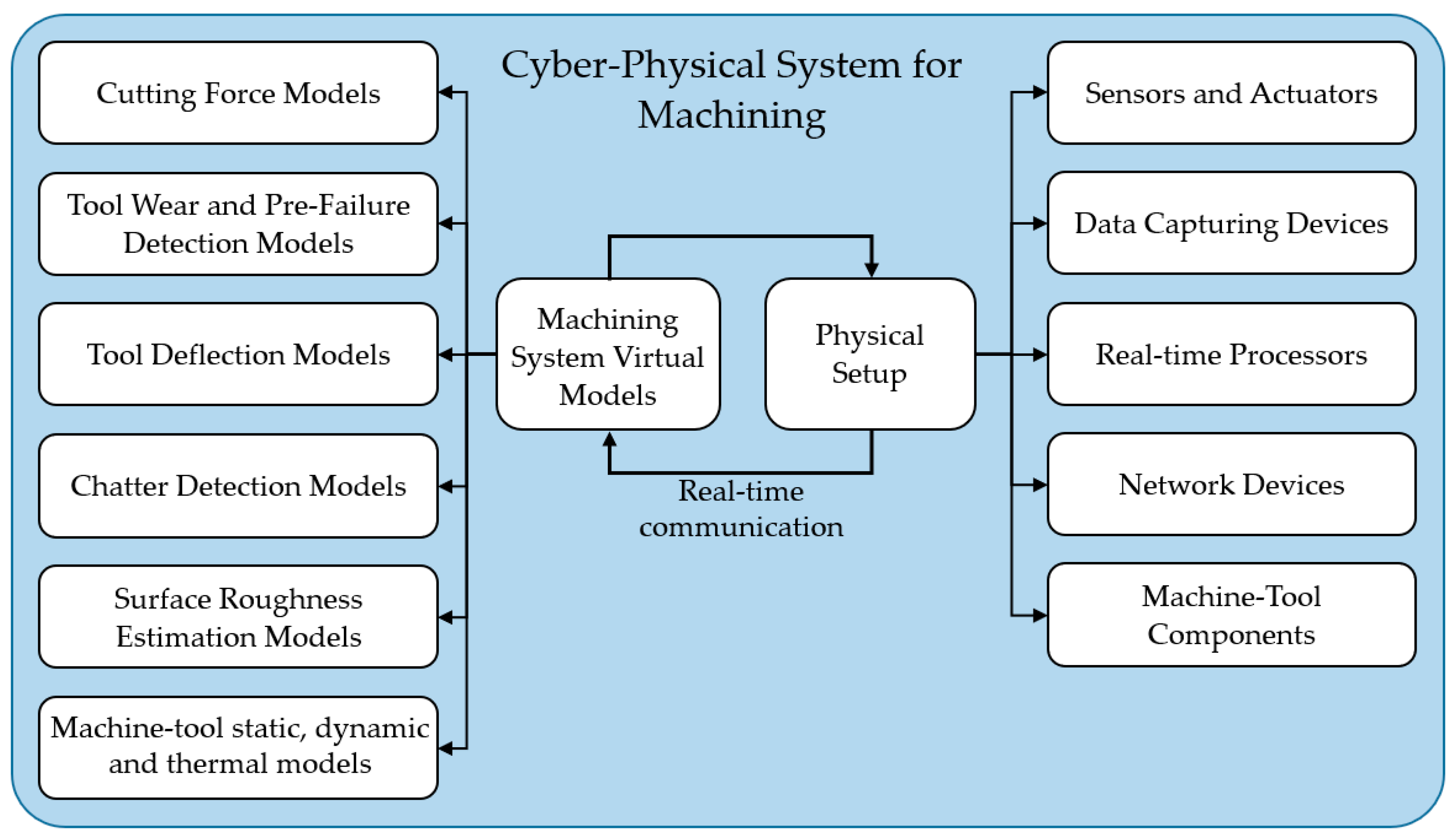
Figure 6 is constructed to present the main components of a cyber-physical system for machining processes. Virtual models for machining states such as cutting force [
193,
194,
195] and surface roughness [
196,
197,
198,
199] are widely investigated. The main approach for estimating cutting forces is to use cutting coefficients extracted from orthogonal cutting tests for a specific set of tool-workpiece materials. The more accurate approach is to simulate the cutting condition using a finite element modeling approach, which can account the effect of the tool and workpiece microstructure evolution and the dependance of the workpiece flow stress on temperature, strain and strain rate, among other factors. The cutting states such as forces and temperature are more accurately determined using the FE approach considering the variations that may exist between the orthogonal tests with the actual cutting conditions. In addition, the force, and temperature distributions with more details can be determined using a chip formation finite element simulation. The tool deflection models, and chatter detection models are discussed in the process optimization section. To fully simulate the machining system, virtual models describing the static, dynamic and thermal deformation of the machine tool structure should be considered and integrated. Static errors in machining refer to inaccuracies in the position of the tool relative to the workpiece. These errors can arise from the geometric inaccuracies in machine and tool components, and the structural deformations caused by gravity and stationary forces [
200]. Traditionally, direct measurement techniques such as using a laser interferometer or electronic levels were used to identify static errors. Indirect approaches such as the multi-line and body diagonal methods have been developed to more efficiently and accurately determine these errors [
201]. There is no clear definition for the dynamic errors so far as extensively reviewed in [
200,
202]. The general assumption is that the dynamic errors are induced due to the feed motions. The dynamic errors could be significantly higher than the static errors, especially during high-speed machining of the sculptured surfaces. The induced errors are not only due to the high feedrates but also due to the acceleration/deceleration generated during the machining of the high curvature geometries and corners [
203]. A common approach is to reduce the errors by interpolating the tool path in a way that limits acceleration and jerk throughout the path [
204,
205]. The work carried out by Attia and Kops introduced the effect of the machine tool structural joints on the machine thermal deformation [
206,
207,
208,
209]. Later, this work was extended from offline predictions to real-time prediction and control to minimize the thermally-induced errors that may reach 50% of the total machining error [
210,
211,
212,
213,
214,
215,
216,
217,
218]. In this section, the material constitutive models, fracture model, and the heat transfer model required for the chip formation simulation are discussed.
As research studies show, proper selection of cutting parameters can reduce the effects of thermal stresses and deformations on the tool and workpiece by conveying more heat through the chip [
219] and applying efficient cooling strategies. Implementing a CPS requires accurate and reliable virtual models to predict the cutting states and determine the optimum cutting parameters. Numerical simulation of a cutting process involves diverse physical models such as material constitutive model, contact friction model, fracture criterion, and heat transfer equations. Finite element analysis (FEA) of a machining process is highly practical and beneficial to determine the proper selection of tool material and provides information to optimize the cutting parameters and develop models to predict tool wear and tool failure. Other numerical models for simulating the machining process include meshless and particle-based methods, discrete element method, and molecular dynamics (MD) simulation method. Meshless methods such as the Smoothed-Particle Hydrodynamics (SPH) have been adopted as an alternative to the widely used FEM to handle the large deformations in the workpiece [
220,
221]. Röthlin et al. [
222] conducted high-resolution SPH simulations using scientific computing on a Graphics Processing Unit GPU. The GPU acceleration of the SPH simulations enabled the inverse identification of constitutive model parameters within a numerical model of the cutting experiment [
223]. Recently, using this numerical framework, computed process forces within the SPH model were used to train a machine learning model of the orthogonal cutting [
223] to improve the accuracy of force predictions than analytical and empirical models at similar low computational times. Another approach to overcome the challenging associated with large strains during the cutting, which induce high deformation in the FE mesh, the Coupled Eulerian-Lagrangian (CEL) method was proposed by Ducobu et al. [
224]. A review of the state-of-the-art in analytical and numerical modeling of conventional metal machining processes to predict chip formation, forces, temperatures, tool wear, residual stress, and microstructure is presented in a recent publication by Melkote et al. [
225].
Recently, artificial intelligence has been employed to improve the efficiency, accuracy, and comprehensiveness of virtual models. DNN methods have been used to predict the chatter status more robustly during a machining process, as mentioned in
Section 2.2. Similarly, learning methods are implemented to predict the specific cutting forces [
226]. In these approaches, training data is required as the input for the learning process that can be acquired from experiments or numerical simulations. Due to the cost of the experiments and the variety of cutting conditions to be tested for training purposes, numerical models are the most feasible strategy. In the simulation of cutting processes, 2D and 3D orthogonal/oblique models of the cutting operation to simulate the chip formation are the prevailing approach due to the simplifications that can be further correlated to a variety of cutting conditions [
226]. In this simulation, the material constitutive model is the first and most important model required to predict the behavior of the material at very high temperatures, strains and strain rates. Deriving a conclusive constitutive model to predict the thermo-mechanical behavior of the material is a crucial and challenging problem. The commonly used constitutive models in machining simulation are discussed in the next section.
The contact friction model determines the frictional stresses acting on the rack and flack faces [
227,
228]. Friction models such as the constant shear friction factor for the whole cutting contact length, and the constant shear friction factor for the sticking zone along with a constant friction coefficient for the sliding zone are the main simplified approaches that are implemented in machining FE simulations. Further sophisticated models to determine variable shear friction factor and friction coefficient have been developed by establishing a relationship between the frictional stresses with the normal pressure, temperature, and strain rate at the contact faces [
221,
229]. Friction models are also widely investigated and tested for FE modeling of chip formation. A crucial model is the fracture criterion required to determine the failure condition for the material elements considering the stresses, temperature, and strain acting on the element. These models were developed for different materials, where the model’s constants are first evaluated and then imported for the cutting simulation. The data needed for the process simulation is the information on thermal boundary conditions which depend on the loading and cutting conditions. This information is particularly crucial if a coolant is present during the cutting process. The information on the thermal boundary conditions is also widely investigated in literature for different materials and cutting operations. The first challenge in the research studies on machining is to predict the elastic-plastic behavior of the machined material alloy considering the strength variation at different temperatures and strain rates. The second challenge is to develop a finite element model (FEM) capable of predicting the cutting states considering the variations in the thermo-mechanical behavior of machined material and the microstructure evolution.
Titanium-based alloys, e.g. Ti6Al4V, are preferred materials for aerospace, automotive and biomedical applications for their high strength-to-weight ratio, high corrosion resistance, their ability to maintain quality at high temperatures and excellent biocompatibility [
230]. However, these properties can significantly hinder their machinability, therefore they can be defined as difficult-to-cut. This can be attributed to their high hardness, abrasion resistance, high strength at elevated temperatures, low thermal conductivity, and high chemical reactivity [
231,
232,
233]. The generated high mechanical and thermal loads on the cutting edge can lead to different mechanisms of tool failure in terms of tool wear, chipping, or breakage. Machining of Ti-alloys is also characterized by the formation of segmental chips, which is governed by a ductile fracture mechanism, resulting in cyclic variation of forces. The resulting vibration can limit the material removal rate, and promote accelerated tool wear. The latter could have a negative influence on the surface integrity of the machined part [
234]. The proper selection of the fracture criterion can significantly diminish the prediction errors in terms of machining forces and machining-induced RS [
234]. In the coming subsections, emphasis will be placed on some specific aspects that are particularly relevant to the modelling and simulation of machining difficult-to-cut materials, namely, the formulation of material constitutive laws, fracture models for predicting the effect of chip segmentation, modelling the material microstructure, and modelling the thermal boundary conditions and heat transfer process during cutting.
3.1. Material Constitutive Models
Material constitutive models describe the elastic and plastic behavior of a material at different temperatures, strains, and strain rates. They are the essential part of finite element simulations of the cutting process which highly affect the efficiency and accuracy of predicting the plastic deformation in the primary, secondary and tertiary deformation zones. The main challenge in the simulation of a chip formation process is to determine the material behavior at severe deformation in a small region that occurs at high temperatures and high strain rates [
236,
237]. One of the widely used constitutive material models to predict the plastic behavior of the material under these conditions is Johnson-Cook (J-C) model [
238]. The main advantage of this model is its capability to estimate the low stress under large deformation. It is computationally more convenient for implementation. The general form of the J-C model is described as follows [
239]:
Where
,
is the flow stress,
is the homologous temperature,
is the strain rate,
A is the yield stress at the reference temperature and reference strain rate, B is the strain hardening coefficient,
C is the strain rate hardening coefficient,
n is the strain hardening exponent and
m is the thermal softening exponent. Each term is interpreted as a thermo-mechanical flow characteristic. The first term,
, depicts the strain hardening phenomenon while the second term
is describing the strain rate effect and third terms
represents the thermal softening effect. Optimization approaches such as PSO and fireworks have been suggested to more accurately determine the coefficients based on a set of experimental data [
240,
241]. Recently it has been suggested to estimate the J-C model parameters through neural network models to eliminate the necessity of extensive experiments and characterize the coefficients based on different cutting conditions which improve the accuracy and efficiency of utilizing the J-C model in finite element simulations [
242]. An in-depth review of the methods to identify the coefficients of the material constitutive models for the cutting processes is presented in [
243] and [
244]. In the studies, a method is developed based on the information obtained from the distributed primary zone deformations (DPZD), the quasi-static indentation (QSI) tests, and the orthogonal cutting tests at room temperature and high temperature, which eliminates the errors in that commonly occurs in the simulation of severe plastic deformation.
Table 6.
Identified Johnson-Cook parameters for Ti6Al4V reported in the literature.
Table 6.
Identified Johnson-Cook parameters for Ti6Al4V reported in the literature.
| Model |
A (MPa) |
B (MPa) |
n |
m |
C |
(1/s) |
| JC-1 [235] |
782.7 |
498.4 |
0.28 |
1 |
0.028 |
10-5
|
| JC-2 [245] |
896.4 |
649.5 |
0.387 |
0.758 |
0.0093 |
1 |
| JC-3 [246,247] |
870 |
990 |
1.01 |
1.4 |
0.008 |
1 |
| JC-4 [248] |
1098 |
1092 |
0.93 |
1.1 |
0.014 |
1 |
The next popular constitutive model is the modified Zerilli-Armstrong model which predicts the flow stress behavior of the material at a certain temperature, strain, and strain rates. Dislocation mechanisms are the main deriving factors to estimate the plastic behavior of the material [
245]. The equation of the modified Zerilli-Armstrong model is shown in equation (2):
where
is the flow stress,
, T is the temperature,
is the reference temperature,
is the strain rate,
to
and n are the material constants. Metaheuristic optimization such as Genetic algorithm has been suggested to reduce the inaccuracies in the determination of the constants [
249,
250].
Table 7.
Modified Zerilli-Armstrong model constants for Ti6Al4V [
245].
Table 7.
Modified Zerilli-Armstrong model constants for Ti6Al4V [
245].
|
|
|
|
|
|
n |
|
| 869.4 |
640.50 |
0.0013 |
-9.57×10⁻⁴
|
0.0095 |
6.94×10⁻⁶
|
0.3867 |
323 |
Another important constitutive model is Voyiadjis-Abed model in which the thermomechanical properties of a material are determined based on a physical-based approach rather than an empirical curve fitting method [
251]. This method is originally developed for pure FCC, BCC, and HCP materials to describe their plastic behavior based on the internal microstructural features [
252]. The Voyiadjis-Abed equation is represented in equation (3).
Where
is the flow stress,
to
are the coefficient related to the internal microstructure characteristics of the material,
and
are the constant exponents and
and
are the determined reference strain rates for yielding and hardening mechanisms.
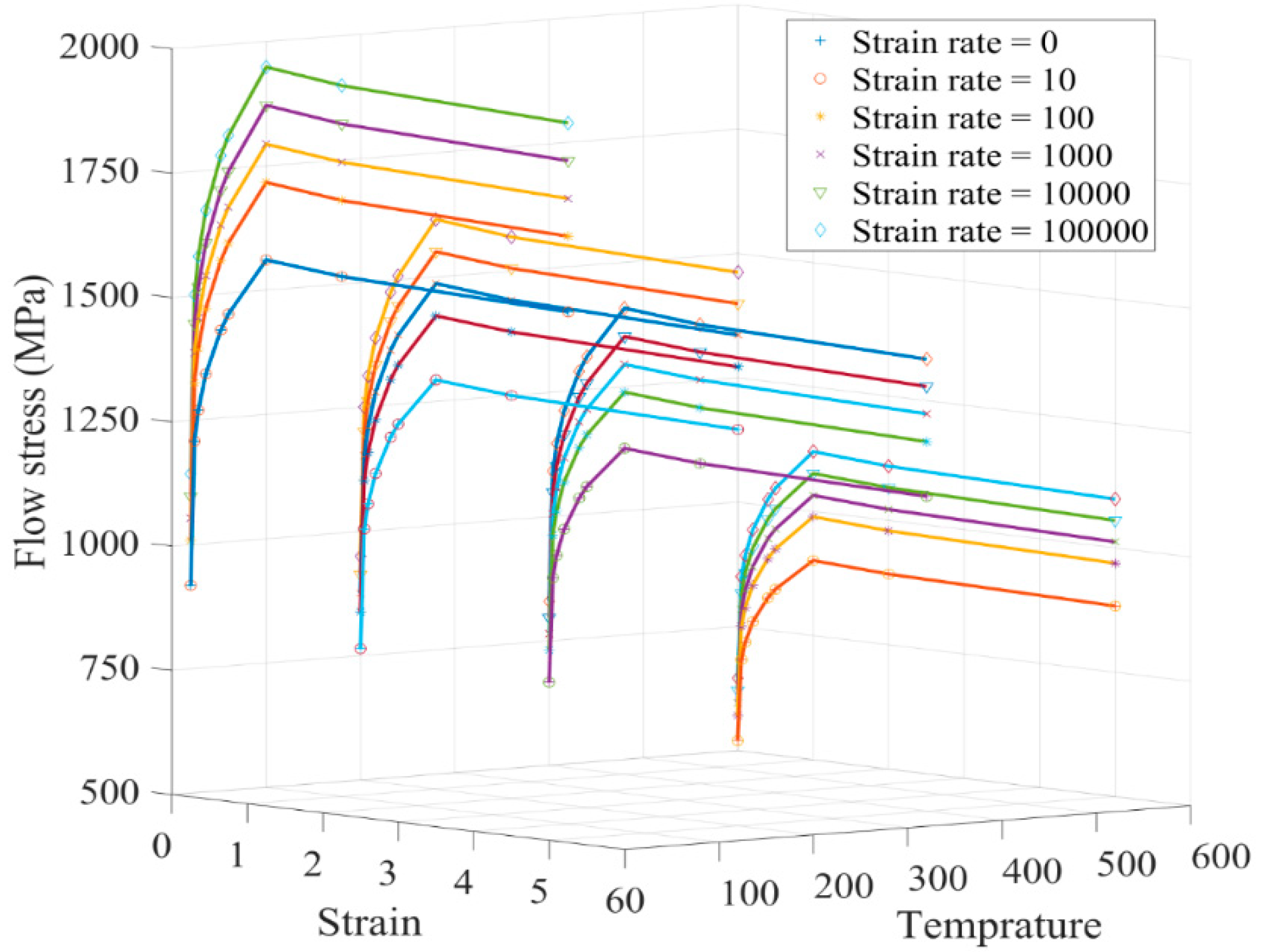
To estimate the flow stress at different stress, strain, strain rate, and temperature, a tabulated flow stress model based on experiments could be constructed. Deform
® is one of the major commercial finite element software developed specifically to simulate manufacturing processes. It employs a tabulated flow stress model as a default approach for the constitutive material model to evaluate the flow stresses. The general format of tabulated flow stress can be represented as
where
is the equivalent flow stress,
is the equivalent strain,
is the strain rate and T is the temperature. A linear weighted average interpolation scheme is used to determine the flow stress based on a set of tabulated data points [
253]. A representation of tabulated flow stress data for the Ti-alloy Ti6Al4V is shown in
Figure 7. This model has more accuracy and compatibility with experimental data and is considered the benchmark to compare the accuracy of the other constitutive models developed for Ti6Al4V [
253]. A study on finite element simulation of the cutting process by Liu et al. [
253] shows that the Johnson-Cook model developed by Leseur [
248] for Ti6Al4V has better compatibility with the Deform® software tabulated data in comparison with the other mentioned approaches.
There have been several attempts to combine machine learning and artificial intelligence in finite element simulation of machining processes [
255,
256,
257]. These approaches can increase the efficiency, reliability, and accuracy of the simulation and can be utilized for a wider range of cutting conditions. They have the flexibility to be interconnected with the physical system and can be used to establish a decision-making core to enhance the information perception and control of the manufacturing system.
3.2. Fracture Model in Chip Formation
As experimentally observed, cyclic chips, also known as serrated or segmented chips, are the dominant chip morphology in the machining of titanium alloys at the conventional cutting speed ranges [
258]. This phenomenon is explained through two main theories known as the ductile fracture mechanic and the adiabatic shear theory [
259]. The ductile fracture mechanic suggests that serrated chips form as a consequence of the crack initiations on the chip's free surface and they spread to the tooltip periodically. The primary shear zone is weakened by periodic cracks, resulting in chip segmentation. The adiabatic shear theory assumes that serrated chips are created by periodic thermoplastic shear instability inside the primary shear zone [
260].
The common fracture model incorporated into modeling chip segmentation in machining Ti6Al4V is Cockroft and Latham’s criterion [
247,
261]. The model can be represented as follows:
In which,
is the equivalent plastic strain at which fracture happens and
is the maximum principal stress and
C is the material damage value. The integral value is calculated for each element in a finite element simulation. If the integral reaches the material constant, the solver considers the element as a damaged element and deletes it. The reported values for the material constant for Ti6Al4V are in the range of 100 to 400 MPa, which can be calibrated through an iterative procedure by comparing the predicted and measured chip geometry and the principal cutting force [
247]. As shown experimentally, cutting speed has a considerable effect on the chip geometry, resulting in rising the frequency of chip segmentation when the cutting speed is increased [
247,
262]. The corresponding material constant in Cockroft and Latham’s criterion increases in the simulation of a high-speed machining condition [
247].
3.3. Thermal Boundary Conditions and Heat Transfer Models
The main sources of heat generation in a cutting operation are the dissipation of plastic deformations to heat in the primary and secondary deformation zones, and the friction-induced heat at the tool-chip interface [
232,
263,
264,
265,
266,
267]. As the studies showed, the generated heat due to the friction at the contact region between the tool and chip is considerably smaller than the heat generated from the plastic deformation in the shear zones. To improve the machinability of the Ti6Al4V alloy and other difficult-to-cut materials, several cooling approaches have been introduced such as minimum quantity lubrication (MQL), cryogenic cooling method, and high-pressure coolant (HPC) [
227,
268,
269,
270]. The cryogenic method is a more advanced approach for cooling the cutting zone, especially for materials with low thermal conductivity [
271]. However, the application of the cryogenic cooling method for Ti6Al4V alloy increases the material hardness, mechanical loads, and tool wear rate [
232,
268]. HCP is recognized as the low-cost and maintenance approach for the cooling process in the machining of Ti alloys [
232]. The cooling information is required in determining the boundary conditions for the designed cutting operation.
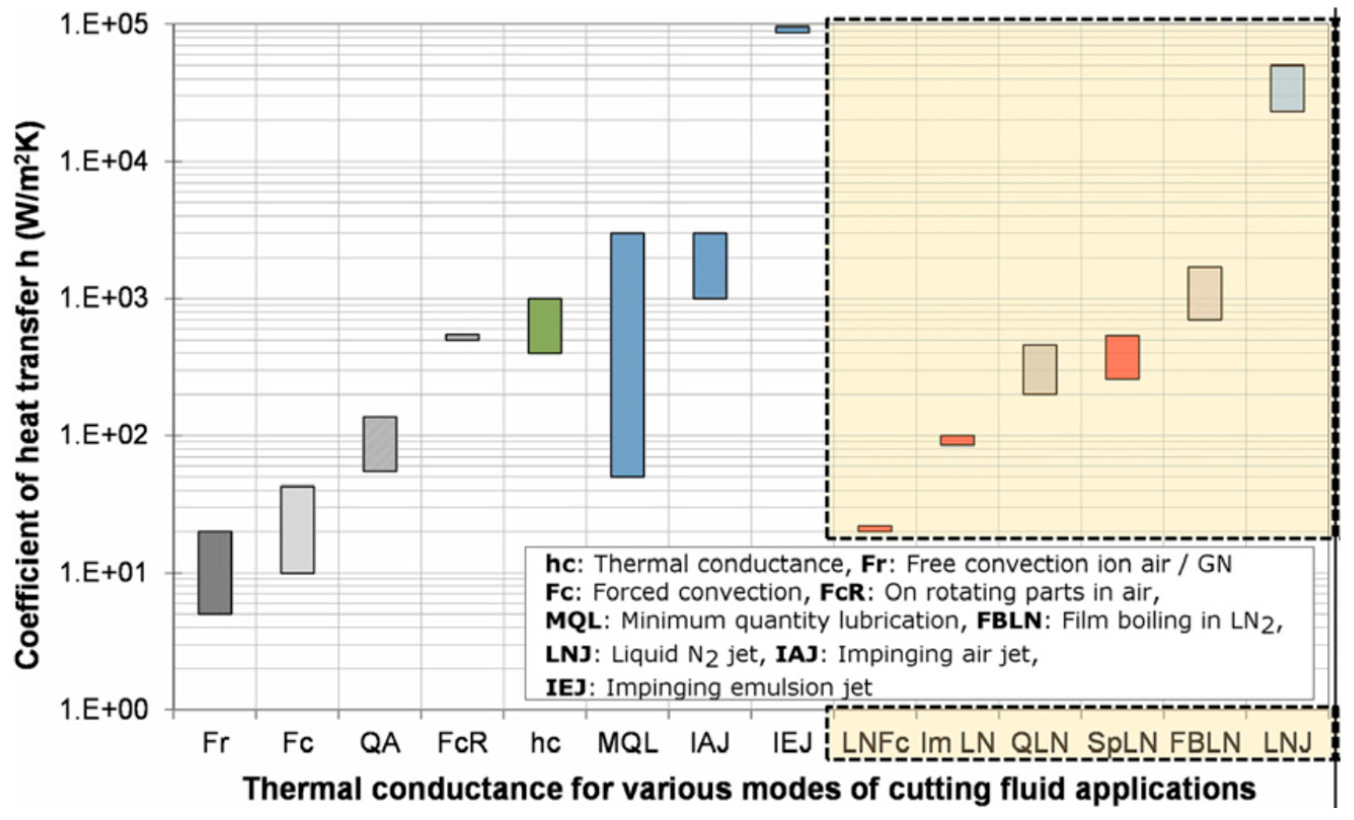
Figure 8 shows the typical ranges of the coefficient of heat transfer (CHT) in machining under different cooling regimes [
270].
Table 9 represents the heat transfer information required in finite element simulation of machining operations.
3.4. Microstructure Modeling
The microstructure modeling of the tool and workpiece material could significantly improve the accuracy of a numerical simulation of a cutting operation, especially for multi-phase materials. Multi-phase materials like cemented carbides are highly affected by internal microstructure features such as grain size, shape and distribution, constituent phases, and interfacial properties [
274,
275,
276]. WC/Co cemented carbide, also referred to as hard metals, is a crucial alloy employed in a variety of industrial tools such as cutting inserts, drilling bits, and dies due to their outstanding combination of hardness and toughness [
274]. The two contributing phases of this alloy known as tungsten carbide (WC) and Cobalt (Co) have different mechanical properties. WC phase is considered the brittle phase which contributes to the hardness of the alloy and behaves elastically under loading conditions, while the Co phase, referred to as binder, is the ductile phase which contributes to the toughness of the alloy and represents elastic-plastic behavior under loading conditions [
277].
To model a heterogeneous material in continuum mechanics, a representative volume element (RVE) is usually developed which represents the microstructural characteristics of the composite material. One of the dominant approaches to developing RVE for a polycrystalline microstructure is to replicate the real microstructure properties of the material captured by a scanning electron microscope (SEM) or electron backscatter diffraction (EBSD) microscope [
276]. Software such as object-oriented finite element (OOF) [
278], OOF3D [
279], and Materials Image Processing and Automated Reconstruction MIPAR™ [
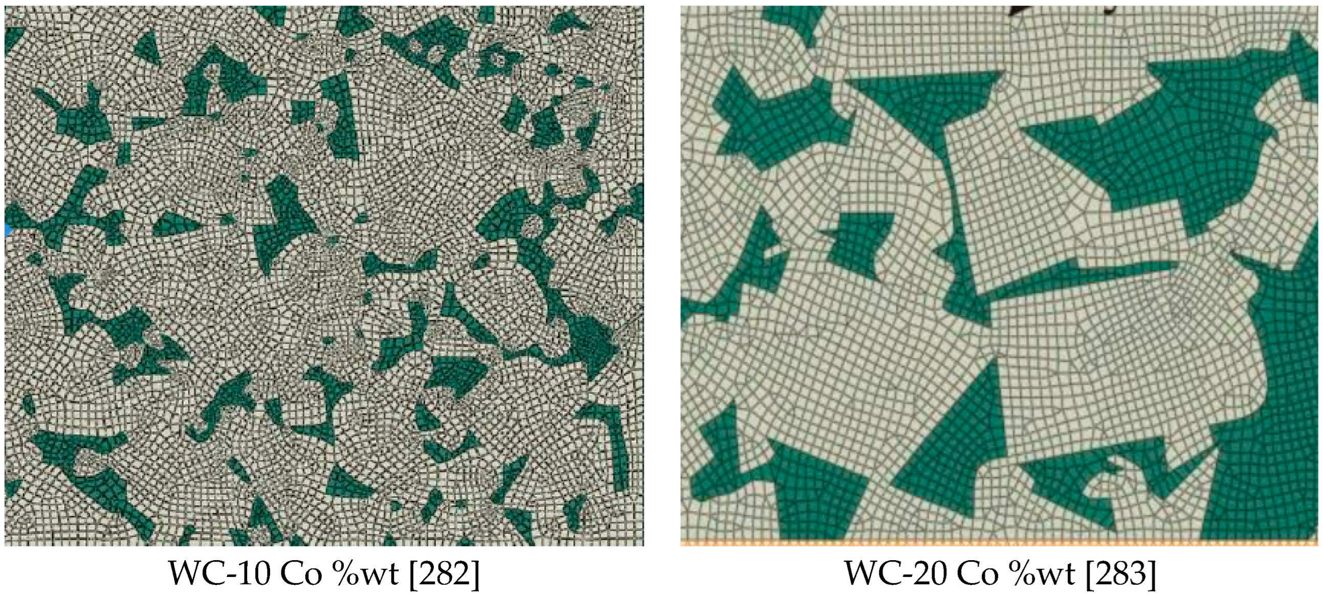
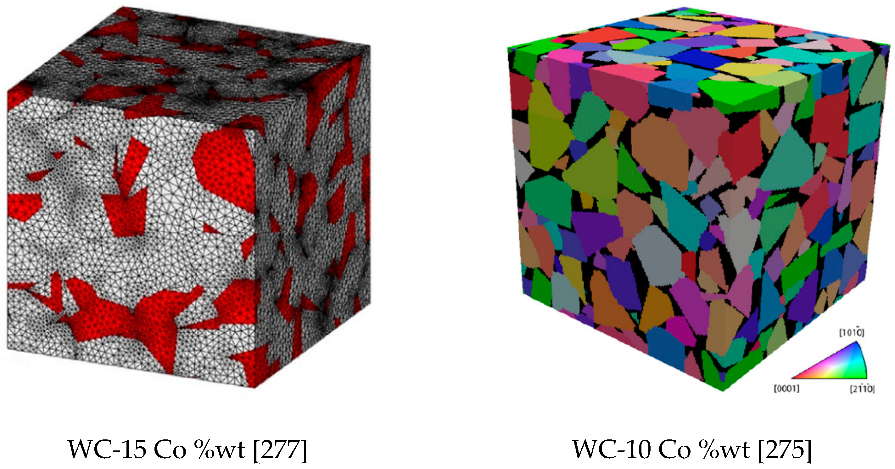
280] have been developed to analyze and segment the images captured from the microstructure of the material. Examples of the constructed real microstructure meshes for the WC/Co microstructure are illustrated in
Figure 9. Machine learning algorithms have been implemented in the image processing of microstructure images to classify the pixels based on the material phases. Pulse-coupled neural networks (PCNN) have been found as a robust method for segmenting the microstructure images for generating FEM meshes [
281].
The second general approach in constructing the multi-phase material microstructure is to synthetically generate the microstructure using various statistical and numerical methods such as Voronoi tessellations [
277,
284,
285], a synthetic grain structure builder (DREAM.3D) [
286,
287], Monte Carlo [
288], and CCBuilder [
275]. The determined microstructure from these approaches can be converted into finite element meshes.
Figure 10 shows two synthetic microstructures generated for WC/Co material based on the (a) Voronoi tessellation method and (b) CCBuilder software. Information such as grain size, grain shape, and neighbor distributions are needed to generate a synthetic microstructure. This information can be extracted from a 2D image of the real microstructure.
3.5. Modelling of Tool Wear Considering the Tool Material Microstructure
The friction between the cutting tool and workpiece during a machining process gradually wears and deforms the cutting edge. The development of the wear mechanisms on the two main sides of the cutting edge has a direct relationship with the cutting time. Five mechanisms are known that contribute to the development of flank wear and crater wear which are: abrasion, attrition, adhesion, diffusion, and oxidation [
2]. The diffusive and oxidation are categorized as the temperature-activated wear mechanisms while abrasion, attrition, and adhesion are the mechanically-activated wear phenomenon [
91,
289]. The occurrence of each type of these mechanisms in a machining operation is dependent on the cutting tool material, workpiece material, and cutting conditions. Diffusive wear occurs during the sliding contact between the tool and the workpiece which facilitates the chemical bonding between the tool materials with the workpiece material. To develop a virtual model for tool wear and pre-failure detection, each of the wear mechanisms is required to be modeled.
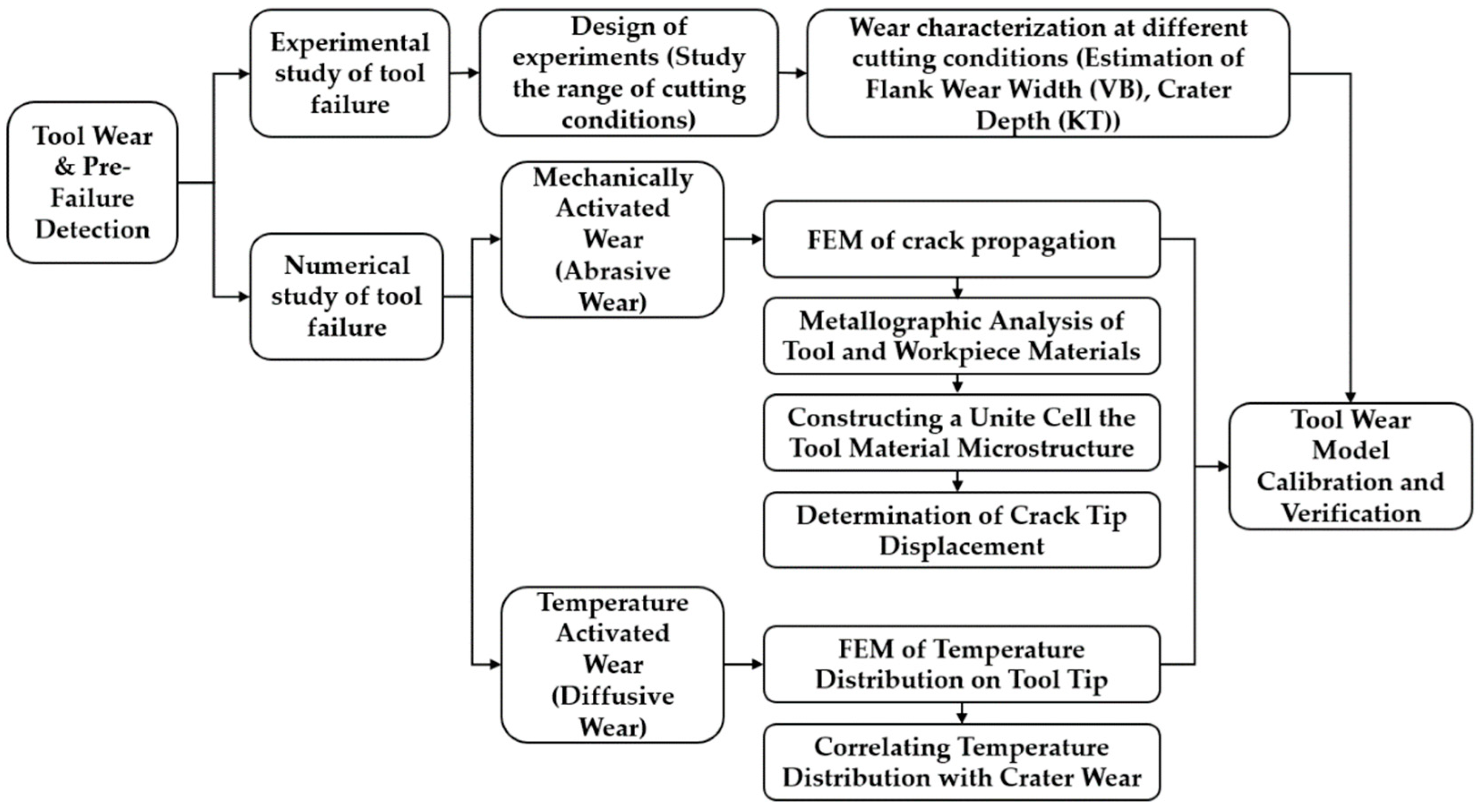
Figure 11 depicts a proposed approach to predict the tool wear and pre-failure detection module. Both mechanically and temperature-activated wear approaches can be considered in developing a virtual model for a cutting process. The intensity of each wear mechanism varies by changing the tool and workpiece material and cutting conditions. As experimentally observed in [
289], mechanically activated wear occurs due to the subsurface crack propagation in the cobalt binder of WC/Co tools.
The temperature-activated wear is numerically or empirically simulated which is critical in the machining of difficult-to-cut materials such as titanium alloys [
290,
291]. Recently, Malakizadi et al. proposed a new approach to predict the thermally-activated dissolution-diffusion wear of carbide tools [
292], considering the effect of the alloying elements on the solubility of tool materials in highly alloyed workpiece materials. A calibrated thermodynamic model is combined with FE model of machining process, which considers the thermal constriction resistance at the tool-chip interface. The approach can efficiently simulate the nonlinear tool wear process without resorting to costly iterative FE simulations.
The mechanically activated wear can be simulated based on the finite element simulation of crack propagation in the tool material [
88,
89,
293,
294]. In order to model the temperature-activated wear mechanism, it is important to determine the temperature distribution at the interfaces of the tool-chip and tool-workpiece. The heat and stress distributions on the tool rake face can be determined using a finite element model of chip formation. This information can then be used to calculate the rate of progression in the size of the crater.
It is found that the cracks are extended through both brittle and ductile phases of WC/Co alloys. The fracture starts in the carbide phase based on a brittle mechanism, and after the creation of a multi-ligament zone (MLZ), it continues through the Co binder in a ductile manner [
295]. The basic assumption for crack propagation under a cyclic load is defined based on the slider motion between two surfaces [
296]. In traditional approaches, the crack propagation is analyzed locally based on the influence of the loading conditions defined away from the cracks. This approach is more accurate to predict the ductile fracture properties for isotropic and homogenous materials [
297]. An important factor in crack propagation analysis is the material resistance to the crack extension which can be varied at different crack lengths and different materials, especially for the materials with elastic-plastic behavior and anisotropic microstructure properties. The two main strategies to simulate the crack propagation in cemented carbides are the simulation of small crack progress based on crack tip displacement (CTD) analysis and the mesoscale crack propagation simulation based on the continuum damage mechanics (CDM). The crack propagation analysis based on CTD criterion is mainly applied for one cycle stress loading conditions [
88,
89,
289].
The first studies on crack propagation in metals revealed the fact that this phenomenon has similarities with delamination crack propagation [
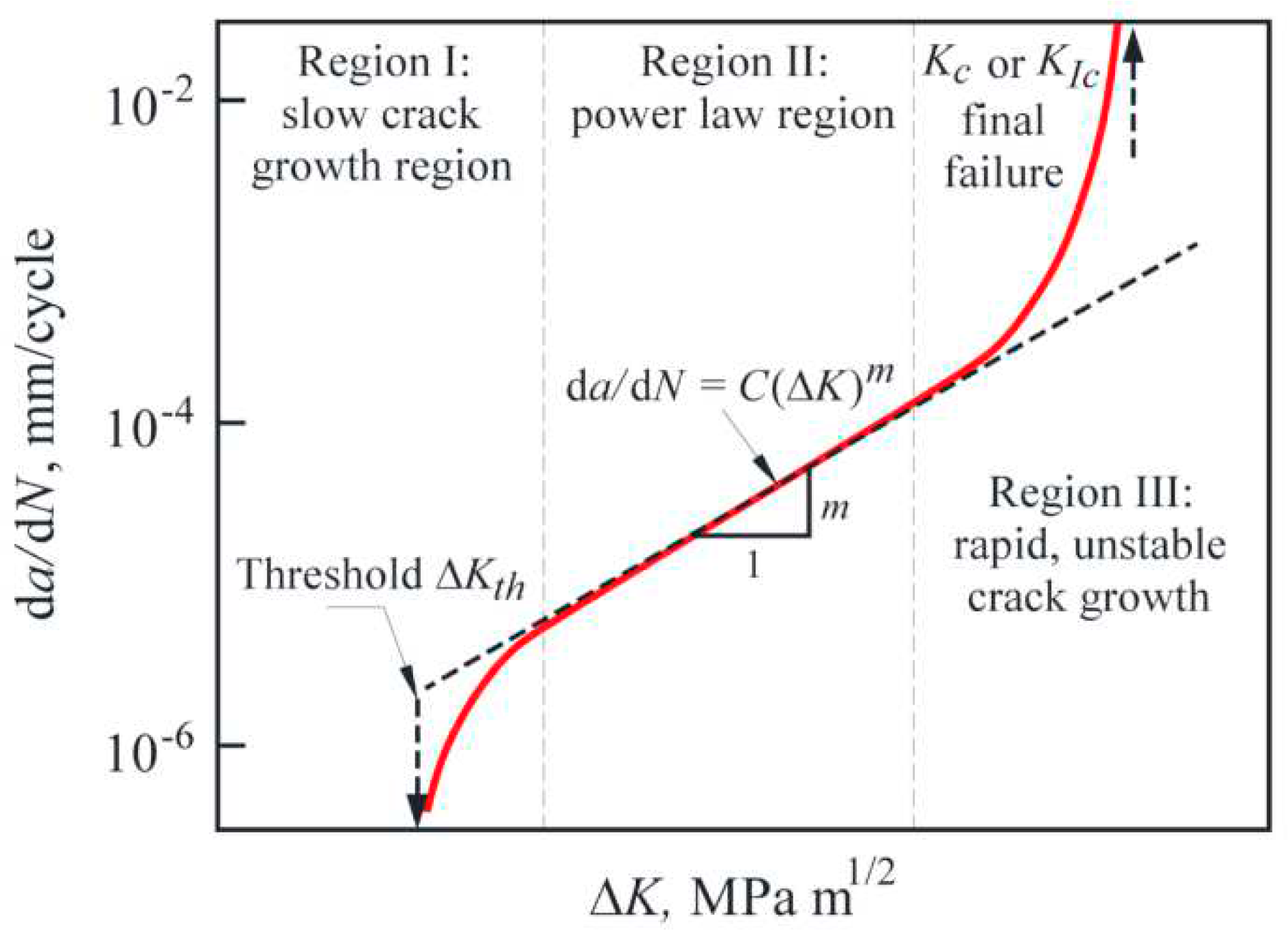
296]. It is observed that the crack growth process consists of three distinguished stages on the plot of crack extension per cycle
) versus the logarithmic scale of the changes in stress intensity factor (
), as shown in
Figure 12. An empirical model is proposed to create a relationship between
and
at the intermediate region where the curve is linear as shown in the following equation [
296]:
where
is the crack length, N is the number of cycles,
is the range of stress intensity factor, and C and n are the material constants.
It was revealed that the crack growth at the first stage occurs due to the extension of small cracks, which cannot be accurately estimated by the linear elastic-plastic fracture mechanics (LEFM) [
289]. The size of the small cracks was found to be in the range of the grain size in monolithic materials and the inter-particle spacing for the composite materials. This phenomenon shows that the real mechanism of crack propagation in small scales is different from the longer cracks [
289]. It was found experimentally that the crack propagation rate (CPR) of small cracks changes by the variations in the crystallographic orientation of the grains and the adjacent cracks [
299] and the small crack propagates along the primary slip system direction [
300]. Shear decohesion of the slip bands near the crack tip is recognized as the crack propagation mechanism for the small cracks where the crack propagates along the direction of maximum shear stress [
301]. The proposed model to determine the propagation rate when there is a mixed mode of loading (normal and shear stresses) is represented in the following equation [
289,
301]:
Where
is the crack tip displacement determined from the primary and secondary slip components calculated at the tip of the crack,
A is an empirical constant, and
n is the exponent of the fatigue crack growth equation. The analytical calculation of
can be extremely complicated [
302]. Further developments revealed that the
can be determined from a finite element modeling to calculate the resultant
from the crack tip sliding displacement
and the crack tip opening displacement
as represented in the following equation [
89,
295]:
where
is defined as the relative displacement of two nodes at the upper and lower crack surface in the tangential direction to the crack plane and
is the relative displacement of two nodes that are attached to the upper and lower crack surface in the normal direction to the crack plane.
is a more accurate crack tip characterizing parameter when the plastic strain energy component is considerably high at the tip of the crack in comparison with the elastic strain energy component [
297].
The mesoscale crack propagation based on CDM is applicable for a high number of cycle loads and can be used to trace the crack extension [
293]. The crack propagation modeling provides information to predict and detect tool failure. There have been studies to correlate the crack propagation rate with the AE emission signal which can be used in the pre-failure detection of cutting tools [
303,
304,
305]. An autonomous and comprehensive approach can be developed for industrial applications that can deal with all the possible uncertainties and disturbances using the introduced hybrid approaches for modeling and optimization of a cutting process.
An essential aspect of a cyber-physical machining system is to predict the tool life and adjust the cutting conditions to utilize the full potential of the tool while avoiding excessive wear rates. A wear model developed based on the finite element of crack propagation in the tool microstructure can determine the wear status more accurately, as presented in [
88,
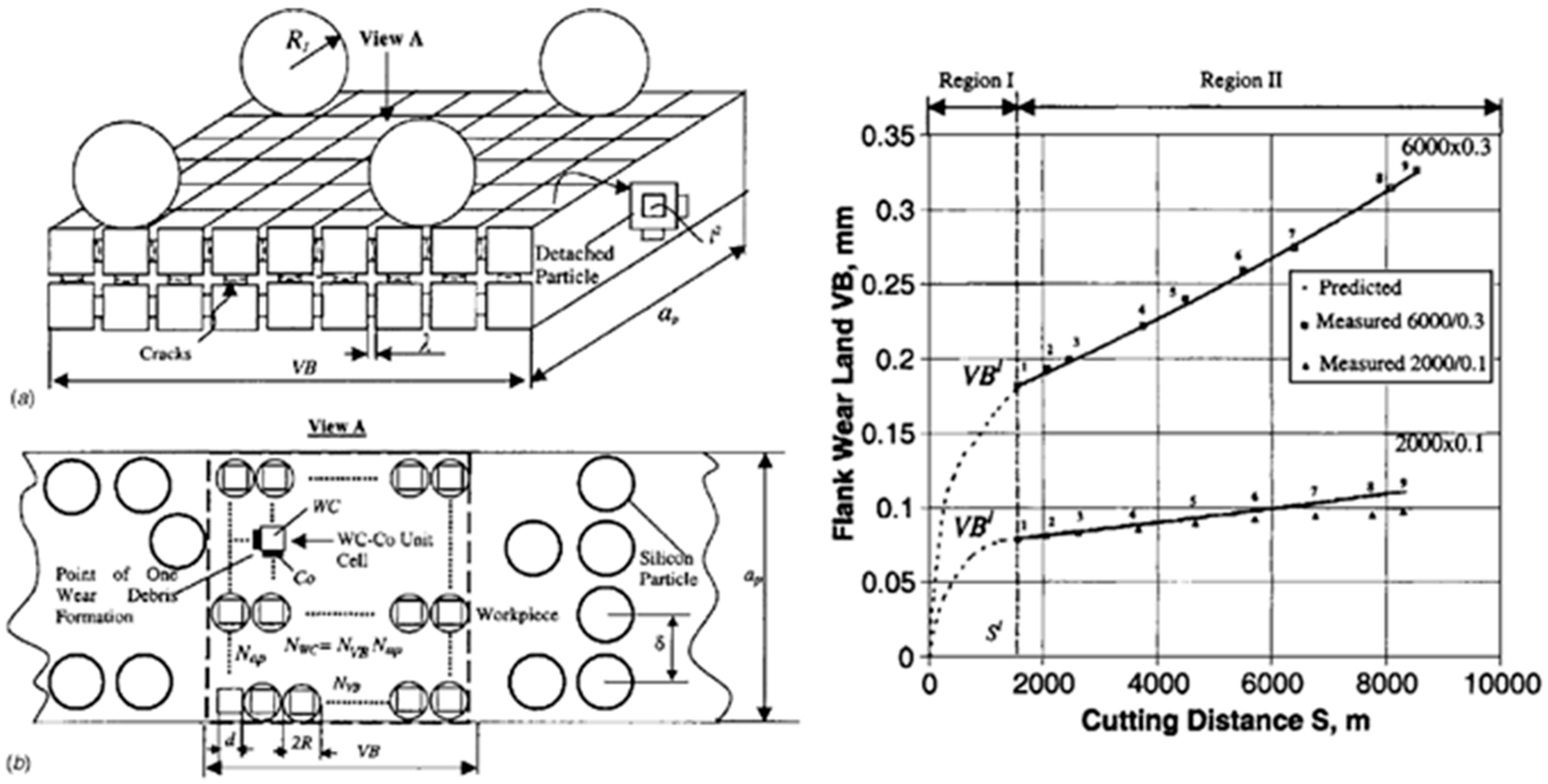
89]. In the study, the flank face of the tool is partitioned based on the average size of the WC grains of the tool material, as shown in
Figure 13a. The normal and tangential stresses acting on the flank land are determined based on the cutting conditions (depth of cut, feed rate, cutting speed), and the tool geometry (rake and clearance angles). The rate of grain detachment was evaluated based on the applied stresses and the number of grains engaged on the flank face.
Figure 13b shows the result of a tool wear model developed based on a simulation of crack propagation in tool microstructure. The figure displays the wear results at two different cutting speeds (2000 and 6000 m/min) and feedrates (mm/tooth). The model could accurately determine the tool wear during the second stage of wear, where the wear behavior is linear with respect to the cutting length. From this information, the changes in the size of the flank wear land can be determined more accurately at different cutting conditions. This model can be combined with a TCM system to account for the uncertainties involved in a cutting operation.
4. Conclusions and Future Outlook
In this comprehensive study of process optimization for cyber-physical systems development, key aspects critical for enhancing machining efficiency were investigated. The initial sections focused on clarifying the diverse objectives and constraints associated with process optimization. Cutting-edge methodologies for process optimization were discussed, with dedicated attention to cutting force-based adaptive control, chatter vibrations avoidance, tool wear management, tool deflection estimation, and the imperative considerations of energy consumption, sustainability, and carbon emission reduction. Subsequently, the material constitutive models, fracture models in chip formation, thermal boundary conditions, heat transfer models, and microstructure modeling were presented and benchmarked for cyber-physical system development. These discussions addressed the challenges facing Industry 5.0 and emphasize the role played by finite element analysis in achieving comprehensive modeling.
The different aspects of process optimization methodologies have been explored to recognize their limits and opportunities to be implemented for industrial applications. The developed online and offline process optimization strategies were reviewed in terms of their objectives and process parameters. The in-depth analysis of the available literature has shown that recent advances in computer control systems, signal processing, and data-driven modeling techniques as well as improving the accuracy and reliability of sensors provided a suitable platform for cyber-physical machine tool system development. However, the implementation of the developed optimization methods for industrial applications is still limited due to the incomprehensiveness and the lack of autonomy for decision-making in the developed methods. In terms of virtual modeling, the implementation of an accurate FE model to simulate complex phenomena such as chip formation and to predict tool chipping and tool wear is highly effective to improve the accuracy of the optimization process. To fully simulate the machining system, virtual models describing the static, dynamic and thermal deformation of the machine tool structure have been considered and integrated. There is need for further investigation on AI-driven FEA to enhance the efficiency of analysis computations and enable real-time microstructure FEA of high number of cycles to reflect the relevant range of the industrial process.
Following are the future outlines concluded from the current state-of-the-art cyber-physical systems for machining:
Due to the technical sophistications in the implementation of the numerical models for industrial applications, it is essential to establish a connection between cutting state numerical models and empirical and AI-based ones to improve their accuracy and reduce the time and cost of the experimental procedure to develop them.
Further research studies are required to consider optimizing cutting parameters that are directly linked to the process sustainability. These optimization approaches have recently become in high demand due to emergence of new aspects that must be considered in industrial production driven by the emerging regulatory obligations and policies mostly related to climate action and energy consumption.
Further studies are required to investigate the crack propagation that can be used to correlate the propagation characteristics with the machining signals such as AE for early prediction and prevention of tool failure.
Finally, the combination of offline machining system models along with online monitoring and multi-objective optimization approaches can provide an all-inclusive cyber-physical machining system which maximizes manufacturing productivity and improve process sustainability and profitability.
