Submitted:
26 January 2024
Posted:
29 January 2024
You are already at the latest version
Abstract
Keywords:
MSC: 78A25; 86A25; 86-08; 65R10; 78M10; 68T07
1. Introduction
2. Mathematical Modeling of TEM Signals
2.1. Sumudu Integral Transform
2.2. Modeling TEM Signals Through Sumudu Transform
2.3. Numerical Inverse Sumudu Transform
2.4. Features of numerical inverse Sumudu transform for TEM signals
2.5. Computational Experiment
2.6. Neural Network Algorithm Development
2.7. Neural Network Algorithm: Results and Discusion
3. Numerical Simulation of TEM Permafrost Monitoring
3.1. Cross-Borehole Measurement System
3.2. Simulation Results on Monitoring Real Objects
3.2.1. Railway in Yakutia
3.2.2. Underground Gas Transmission Pipeline on the Gyda Peninsula
5. Conclusions
Author Contributions
Funding
Data Availability Statement
Acknowledgments
Conflicts of Interest
References
- Smith, S.L.; O’Neill, H.B.; Isaksen, K.; Noetzli, J.; Romanovsky, V.E. The changing thermal state of permafrost. Nat. Rev. Earth Environ. 2022, 3, 10–23. [Google Scholar] [CrossRef]
- Miner, K.R.; Turetsky, M.R.; Malina, E.; Bartsch, A.; Tamminen, J.; McGuire, A.D.; Fix, A.; Sweeney, C.; Elder, C.D.; Miller, C.E. Permafrost carbon emissions in a changing Arctic. Nat. Rev. Earth Environ. 2022, 3, 55–67. [Google Scholar] [CrossRef]
- Nitzbon, J.; Westermann, S.; Langer, M.; Martin, L.C.P.; Strauss, J.; Laboor, S.; Boike, J. Fast response of cold ice-rich permafrost in northeast Siberia to a warming climate. Nat. Commun. 2020, 11, 1–11. [Google Scholar] [CrossRef] [PubMed]
- Hjort, J.; Karjalainen, O.; Aalto, J.; Westermann, S.; Romanovsky, V.E.; Nelson, F.E.; Etzelmüller, B.; Luoto, M. Degrading permafrost puts Arctic infrastructure at risk by mid-century. Nat. Commun. 2018, 9, 1–9. [Google Scholar] [CrossRef] [PubMed]
- Hjort, J.; Streletskiy, D.; Doré, G.; Wu, Q.; Bjella, K.; Luoto, M. Impacts of permafrost degradation on infrastructure. Nat. Rev. Earth Environ. 2022, 3, 24–38. [Google Scholar] [CrossRef]
- Streletskiy, D.A.; Clemens, S.; Lanckman, J.-P.; Shiklomanov, N.I. The costs of Arctic infrastructure damages due to permafrost degradation. Environ. Res. Lett. 2023, 18, 1–13. [Google Scholar] [CrossRef]
- Langer, M.; von Deimling, T.S.; Westermann, S.; Rolph, R.; Rutte, R.; Antonova, S.; Rachold, V.; Schultz, M.; Oehme, A.; Grosse, G. Thawing permafrost poses environmental threat to thousands of sites with legacy industrial contamination. Nat. Commun. 2023, 14, 1–11. [Google Scholar] [CrossRef] [PubMed]
- Best, M.; Fage, I.; Ryan, S. Mapping the Distribution of Permafrost using the Resolve Airborne EM System: Klondike Highway, Yukon, Canada. Recorder 2019, 44, 1–12. [Google Scholar]
- Kaiser, S.; Boike, J.; Grosse, G.; Langer, M. The Potential of UAV Imagery for the Detection of Rapid Permafrost Degradation: Assessing the Impacts on Critical Arctic Infrastructure. Remote Sens. 2022, 14, 1–21. [Google Scholar] [CrossRef]
- Varlamov, S.P. Thermal monitoring of railway subgrade in a region of ice-rich permafrost, Yakutia, Russia. Cold Reg. Sci. Technol. 2018, 155, 184–192. [Google Scholar] [CrossRef]
- Liu, H.; Huang, S.; Xie, C.; Tian, B.; Chen, M.; Chang, Z. Monitoring Roadbed Stability in Permafrost Area of Qinghai–Tibet Railway by MT-InSAR Technology. Land 2023, 12, 1–19. [Google Scholar] [CrossRef]
- Ma, D.; Motagh, M.; Liu, G.; Zhang, R.; Wang, X.; Zhang, B.; Xiang, W.; Yu, B. Thaw Settlement Monitoring and Active Layer Thickness Retrieval Using Time Series COSMO-SkyMed Imagery in Iqaluit Airport. Remote Sens. 2022, 14, 1–21. [Google Scholar] [CrossRef]
- Guo, M.; Lu, Y.; Yu, W.; Xu, L.; Hu, D.; Chen, L. Permafrost change and its engineering effects under climate change and airport construction scenarios in northeast China. Transp. Geotech. 2023, 43, 1–13. [Google Scholar] [CrossRef]
- Feodorov, A.B.; Egorov, A.V.; Pavlova, P.L.; Sviridov, L.I.; Zagorulko, V.N. Analysis of permafrost conditioning in the oil field. J. Phys. Conf. Ser. 2020, 1515, 1–5. [Google Scholar] [CrossRef]
- Vasiliev, G.G.; Dzhaljabov, A.A.; Leonovich, I.A. Analysis of the causes of engineering structures deformations at gas industry facilities in the permafrost zone. J. Min. Inst. 2021, 249, 377–385. [Google Scholar] [CrossRef]
- Pashilov, M.V. Findings of thermometric monitoring of the top layer of permafrost during hydrocarbon production in the European North of Russia. Arct. Environ. Res. 2018, 18, 53–61. [Google Scholar] [CrossRef]
- Chuvilin, E.; Tipenko, G.; Bukhanov, B.; Istomin, V.; Pissarenko, D. Simulating Thermal Interaction of Gas Production Wells with Relict Gas Hydrate-Bearing Permafrost. Geosciences 2022, 12, 1–18. [Google Scholar] [CrossRef]
- Wang, F.; Li, G.; Ma, W.; Wu, Q.; Serban, M.; Samsonova, V.; Fedorov, A.; Jiang, N.; Wang, B. Pipeline–permafrost interaction monitoring system along the China–Russia crude oil pipeline. Eng. Geol. 2019, 254, 113–125. [Google Scholar] [CrossRef]
- Varlamov, S.; Skryabin, P.; Zhirkov, A.; Wen, Z. Monitoring the Permafrost Conditions along Pipeline Routes in Central Yakutia, Russia. Land 2022, 11, 1–15. [Google Scholar] [CrossRef]
- Rajendran, S.; Sadooni, F.N.; Al-Kuwari, H.A.S.; Anisimov, O.; Govil, H.; Nasir, S.; Vethamony, P. Monitoring oil spill in Norilsk, Russia using satellite data. Sci. Rep. 2021, 11, 1–20. [Google Scholar] [CrossRef] [PubMed]
- Belash, T.A.; Dymov, E.A. Influence of Tanks Design Features on Earthquake Resistance in Permafrost Areas. IOP Conf. Ser. Earth Environ. Sci. 2022, 988, 1–6. [Google Scholar] [CrossRef]
- Zhao, X.; Wang, J. Numerical Studies of Bridge Foundation Temperature Control Technology in Permafrost Regions. Abbreviated Journal Name 2020, 455, 1–4. [Google Scholar] [CrossRef]
- Fedin, K.V.; Olenchenko, V.V.; Osipova, P.S.; Pechenegov, D.A.; Kolesnikov, Yu.I.; Ngomayezwe, L. Assessment of the technical condition of bridges and their ground foundations using the electrical resistivity tomography and the passive seismic standing wave method. J. Appl. Geophys. 2023, 217, 1–8. [Google Scholar] [CrossRef]
- Shaidurov, G.Ya.; Amelchugov, S.P.; Igolkin, V.I.; Tronin, O.A.; Radaev, V.V. Physical basis of the remote monitoring method of pile foundations of building structures in permafrost areas. J. Phys. Conf. Ser. 2019, 1399, 1–7. [Google Scholar] [CrossRef]
- Hou, X.; Chen, J.; Yang, B.; Wang, J.; Dong, T.; Rui, P.; Mei, Q. Monitoring and simulation of the thermal behavior of cast-in-place pile group foundations in permafrost regions. Cold Reg. Sci. Technol. 2022, 196, 1–10. [Google Scholar] [CrossRef]
- Ye, Y.; Li, L.; Xu, X. Physical and Mechanical Properties of Transmission Line Galloping under the Action of Freezing and Thawing in Variable Temperature Range. Adv. Civ. Eng. 2021, 2021, 1–10. [Google Scholar] [CrossRef]
- Zhang, J.; Zhou, C.; Zhang, Z.; Melnikov, A.; Jin, D.; Zhang, S. Physical Model Test and Heat Transfer Analysis on Backfilling Construction of Qinghai-Tibet Transmission Line Tower Foundation. Energies 2022, 15, 1–15. [Google Scholar] [CrossRef]
- Bartsch, A.; Strozzi, T.; Nitze, I. Permafrost Monitoring from Space. Surv. Geophys. 2023, 44, 1579–1613. [Google Scholar] [CrossRef]
- de la Barreda-Bautista, B.; Boyd, D.S.; Ledger, M.; Siewert, M.B.; Chandler, C.; Bradley, A.V.; Gee, D.; Large, D.J.; Olofsson, J.; Sowter, A.; Sjögersten, S. Towards a Monitoring Approach for Understanding Permafrost Degradation and Linked Subsidence in Arctic Peatlands. Remote Sens. 2022, 14, 1–19. [Google Scholar] [CrossRef]
- Fraser, R.H.; Leblanc, S.G.; Prevost, C.; van der Sluijs, J. Towards precise drone-based measurement of elevation change in permafrost terrain experiencing thaw and thermokarst. Drone Syst. Appl. 2022, 10, 406–426. [Google Scholar] [CrossRef]
- Zhang, P.; Chen, Y.; Ran, Y.; Chen, Y. Permafrost Early Deformation Signals before the Norilsk Oil Tank Collapse in Russia. Remote Sens. 2022, 14, 1–18. [Google Scholar] [CrossRef]
- Cheng, F.; Lindsey, N.J.; Sobolevskaia, V.; Dou, S.; Freifeld, B.; Wood, T.; James, S.R.; Wagner, A.M.; Ajo-Franklin, J.B. Watching the Cryosphere thaw: Seismic monitoring of permafrost degradation using distributed acoustic sensing during a controlled heating experiment. Geophys. Res. Lett. 2022, 49, 1–11. [Google Scholar] [CrossRef]
- Lebedev, M.; Dorokhin, K. Application of Cross-Hole Tomography for Assessment of Soil Stabilization by Grout Injection. Geosciences 2019, 9, 1–11. [Google Scholar] [CrossRef]
- Konstantinov, P.; Zhelezniak, M.; Basharin, N.; Misailov, I.; Andreeva, V. Establishment of Permafrost Thermal Monitoring Sites in East Siberia. Land 2020, 9, 1–10. [Google Scholar] [CrossRef]
- Noetzli, J.; Arenson, L.U.; Bast, A.; Beutel, J.; Delaloye, R.; Farinotti, D.; Gruber, S.; Gubler, H.; Haeberli, W.; Hasler, A.; Hauck, C.; Hiller, M.; Hoelzle, M.; Lambiel, C.; Pellet, C.; Springman, S.M.; Vonder Muehll, D.; Phillips, M. Best Practice for Measuring Permafrost Temperature in Boreholes Based on the Experience in the Swiss Alps. Front. Earth Sci. 2021, 9, 1–20. [Google Scholar] [CrossRef]
- Isaksen, K.; Lutz, J.; Sørensen, A.M.; Godøy, Ø.; Ferrighi, L.; Eastwood, S.; Aaboe, S. Advances in operational permafrost monitoring on Svalbard and in Norway. Environ. Res. Lett. 2022, 17, 1–13. [Google Scholar] [CrossRef]
- Zhang, J.; Revil, A. Cross-well 4-D resistivity tomography localizes the oil–water encroachment front during water flooding. Geophys. J. Int. 2015, 201, 343–354. [Google Scholar] [CrossRef]
- Commer, M.; Doetsch, J.; Dafflon, B.; Wu, Y.; Daley, T.M.; Hubbard, S.S. Time-lapse 3-D electrical resistance tomography inversion for crosswell monitoring of dissolved and supercritical CO2 flow at two field sites: Escatawpa and Cranfield, Mississippi, USA. Int. J. Greenh. Gas Con. 2016, 49, 297–311. [Google Scholar] [CrossRef]
- Palacios, A.; Ledo, J.J.; Linde, N.; Luquot, L.; Bellmunt, F.; Folch, A.; Marcuello, A.; Queralt, P.; Pezard, P.A.; Martínez, L.; del Val, L.; Bosch, D.; Carrera, J. Time-lapse cross-hole electrical resistivity tomography (CHERT) for monitoring seawater intrusion dynamics in a Mediterranean aquifer. Hydrol. Earth Syst. Sci. 2020, 24, 2121–2139. [Google Scholar] [CrossRef]
- Herring, T.; Lewkowicz, A.G.; Hauck, C.; Hilbich, C.; Mollaret, C.; Oldenborger, G.A.; Uhlemann, S.; Farzamian, M.; Calmels, F.; Scandroglio, R. Best practices for using electrical resistivity tomography to investigate permafrost. Permafr. Periglac. Process. 2023, 34, 494–512. [Google Scholar] [CrossRef]
- Campbell, S.; Affleck, R.T.; Sinclair, S. Ground-penetrating radar studies of permafrost, periglacial, and near-surface geology at McMurdo Station, Antarctica. Cold Reg. Sci. Technol. 2018, 148, 38–49. [Google Scholar] [CrossRef]
- Mozaffari, A. Towards 3D crosshole GPR full-waveform inversion. PhD Thesis, RWTH Aachen University, Germany, May 2022. [Google Scholar]
- Pongrac, B.; Gleich, D.; Malajner, M.; Sarjaš, A. Cross-Hole GPR for Soil Moisture Estimation Using Deep Learning. Remote Sens. 2023, 15, 1–17. [Google Scholar] [CrossRef]
- Léger, E.; Saintenoy, A.; Serhir, M.; Costard, F.; Grenier, C. Brief communication: Monitoring active layer dynamics using a lightweight nimble ground-penetrating radar system – a laboratory analogue test case. Cryosphere 2023, 17, 1271–1277. [Google Scholar] [CrossRef]
- Li, X.; Cao, L.; Cao, H.; Wei, T.; Liu, L.; Yang, X. 2D cross-hole electromagnetic inversion algorithms based on regularization algorithms. J. Geophys. Eng. 2023, 20, 1030–1042. [Google Scholar] [CrossRef]
- Wang, X.; Shen, J.; Wang, Z. 3D general-measure inversion of crosswell EM data using a direct solver. Abbreviated Journal Name 2021, 18, 124–133. [Google Scholar] [CrossRef]
- Cao, L.; Li, X.; Cao, H.; Liu, L.; Wei, T.; Yang, X. 3-D Crosswell electromagnetic inversion based on IRLS norm sparse optimization algorithms. J. Appl. Geophys. 2023, 214, 1–16. [Google Scholar] [CrossRef]
- Oldenborger, G.A.; LeBlanc, A.-M. Monitoring changes in unfrozen water content with electrical resistivity surveys in cold continuous permafrost. Geophys. J. Int. 2018, 215, 965–977. [Google Scholar] [CrossRef]
- Tomaškovičová, S.; Ingeman-Nielsen, T. Quantification of freeze–thaw hysteresis of unfrozen water content and electrical resistivity from time lapse measurements in the active layer and permafrost. Permafr. Periglac. Process. 2023, Volume, 1–19. [Google Scholar] [CrossRef]
- Boaga, J.; Phillips, M.; Noetzli, J.; Haberkorn, A.; Kenner, R.; Bast, A. A Comparison of Frequency Domain Electro-Magnwtometry, Electrical Resistivity Tomography and Borehole Temperatures to Assess the Presence of Ice in a Rock Glacier. Front. Earth Sci. 2020, 8, 1–11. [Google Scholar] [CrossRef]
- Kim, K.; Lee, J.; Ju, H.; Jung, J.Y.; Chae, N.; Chi, J.; Kwon, M.J.; Lee, B.Y.; Wagner, J.; Kim, J.-S. Time-lapse electrical resistivity tomography and ground penetrating radar mapping of the active layer of permafrost across a snow fence in Cambridge Bay, Nunavut Territory, Canada: correlation interpretation using vegetation and meteorological data. Geosci. J. 2021, 25, 877–890. [Google Scholar] [CrossRef]
- Buddo, I.; Sharlov, M.; Shelokhov, I.; Misyurkeeva, N.; Seminsky, I.; Selyaev, V.; Agafonov, Y. Applicability of Transient Electromagnetic Surveys to Permafrost Imaging in Arctic West Siberia. Energies 2022, 15, 1–16. [Google Scholar] [CrossRef]
- Yang, G.; Xie, C.; Wu, T.; Wu, X.; Zhang, Y.; Wang, W.; Liu, G. Detection of permafrost in shallow bedrock areas with the opposing coils transient electromagnetic method. Front. Environ. Sci. 2022, 10, 1–14. [Google Scholar] [CrossRef]
- Koshurnikov, A.V. The Principles of Complex Geocryological Geophysical Analysis for Studying Permafrost and Gas Hydrates on the Arctic Shelf of Russia. Moscow Univ. Geol. Bull. 2020, 75, 425–434. [Google Scholar] [CrossRef]
- Swidinsky, A.; Weiss, C.J. On coincident loop transient electromagnetic induction logging. Geophys. 2017, 82, 1JA–Z33. [Google Scholar] [CrossRef]
- Zhu, X.; Liu, J.; Shen, J.; Shen, Y. Transient Electromagnetic Response of Electrode Excitation and Geometric Factors of Desired Signal. In Transactions of the SPWLA 63rd Annual Logging Symposium, Stavanger, Norway, 11–15 June 2022. [CrossRef]
- Nikitenko, M.N.; Glinskikh, V.N.; Mikhaylov, I.V.; Fedoseev, A.A. Mathematical Modeling of Transient Electromagnetic Sounding Signals for Monitoring the State of Permafrost. Russ. Geol. Geophys. 2023, 64, 488–494. [Google Scholar] [CrossRef]
- Glinskikh, V.; Nechaev, O.; Mikhaylov, I.; Danilovskiy, K.; Olenchenko, V. Pulsed Electromagnetic Cross-Well Exploration for Monitoring Permafrost and Examining the Processes of Its Geocryological Changes. Geosciences 2021, 11, 1–15. [Google Scholar] [CrossRef]
- Mikhaylov, I.V.; Nechaev, O.V.; Glinskikh, V.N.; Nikitenko, M.N.; Fedoseev, A.A. Numerical simulation of cross-borehole impulsed electromagnetic signals for permafrost monitoring under bases of industrial facilities. Geophys. Res. 2023, 24, 87–102. [Google Scholar] [CrossRef]
- Bukhtiyarov, D.A.; Glinskikh, V.N. Preliminary results of clay soils state monitoring using transient electromagnetic sounding apparatus. Russ. J. Geophys. Techn. 2022, 2, 44–64. [Google Scholar] [CrossRef]
- Glinskikh, V.N.; Fedoseev, A.A.; Nikitenko, M.N.; Mikhaylov, I.V.; Bukhtiyarov, D.A. Design of field experiments for substantiation of permafrost monitoring technology. Earth’s Cryosph. 2023, 27, page range. [Google Scholar] [CrossRef]
- Epov, M.I.; Nechaev, O.V.; Glinskikh, V.N. Numerical inversion of the Sumudu integral transform in the simulation of electromagnetic sounding of the Earth’s interior. Russ. Geol. Geophys. 2023, 64, 860–869. [Google Scholar] [CrossRef]
- Epov, M.I.; Danilovskiy, K.N.; Nechaev, O.V.; Mikhaylov, I.V. Artificial neural network-based computational algorithm of inverse Sumudu transform applied to surface transient electromagnetic sounding method. Russ. Geol. Geophys. 2023, 1–7. [Google Scholar] [CrossRef]
- Watugala, G.K. Sumudu transform a new integral transform to solve differential equations and control engineering problems. Int. J. Math. Educ. Sci. Technol. 1993, 24, 35–43. [Google Scholar] [CrossRef]
- Tabarovsky, L.A.; Sokolov, V.P. ALEKS: a software for modeling dipole source TEM responses of a layered earth. In Electromagnetic Methods in Geophysics; Antonov, Yu.N., Dashevsky, Yu.A., Morozova, G.M., Sokolov, V.P., Eds.; IGiG SO AN SSSR: Novosibirsk, USSR, 1982; pp. 57–77. [Google Scholar]
- Gradshteyn, I.S.; Ryzhik, I.M. Table of Integrals, Series, and Products, 7th ed.; Elsevier Academic Press: USA, 2007; 1171p. [Google Scholar]
- Belgacem, F.M.; Karaballi, A.A. Sumudu transform fundamental properties investigations and applications. J. Appl. Math. Stoch. Anal. 2006, 2006, 1–23. [Google Scholar] [CrossRef]
- Belgacem, F.M. Introducing and analysing deeper Sumudu properties. Nonlinear Stud. 2006, 13, 23–41. [Google Scholar]
- Danilovskiy, K.N.; Petrov, A.M.; Asanov, O.O.; Sukhorukova, K.V. Deep-learning-based noniterative 2D-inversion of unfocused lateral logs. Russ. Geol. Geophys. 2023, 64, 109–115. [Google Scholar] [CrossRef]
- Shimelevich, M.I.; Rodionov, E.A.; Obornev, I.E.; Obornev, E.A. 3D neural network inversion of field geoelectric data with calculating posterior estimates. Izv. Phys. Solid Earth 2022, 58, 605–614. [Google Scholar] [CrossRef]
- Epov, M.I.; Shurina, E.P.; Nechaev, O.V. 3D forward modeling of vector field for induction logging problems. Russ. Geol. Geophys. 2007, 48, 770–774. [Google Scholar] [CrossRef]
- Nair, M.T. Quadrature based collocation methods for integral equations of the first kind. Adv. Comput. Math. 2012, 36, 315–329. [Google Scholar] [CrossRef]
- Tikhonov, A.N.; Arsenin, V.Ya. Methods of Solution of Ill-Posed Problems, 2nd ed.; Nauka: Moscow, USSR, 1979; 288p. [Google Scholar]
- Leonov, A.S. Justification of the choice of the regularization parameter according to quasi-optimality and quotient criteria. USSR Comput. Math. Math. Phys. 1978, 18, 1–15. [Google Scholar] [CrossRef]
- Nabighian, M.N. (Ed.) Electromagnetic methods in applied geophysics. Vol. 1. Theory; SEG: Oklahoma, USA, 1988; 531p. [Google Scholar] [CrossRef]
- Krizhevsky, A.; Sutskever, I.; Hinton, G.E. ImageNet classification with deep convolutional neural networks. Adv. Neural Inf. Process. Syst. 2012, 25, 1097–1105. [Google Scholar] [CrossRef]
- McCulloch, W.S.; Pitts, W. A logical calculus of the ideas immanent in nervous activity. Bull. Math. Biophys 1943, 5, 115–133. [Google Scholar] [CrossRef]
- Cybenko, G. Approximation by superpositions of a sigmoidal function. Math. Control Signals Syst. 1989, 2, 303–314. [Google Scholar] [CrossRef]
- Kingma, D.P.; Ba, J. Adam: a method for stochastic optimization. In Proceedings of the 3rd International Conference for Learning Representations, San Diego, California, USA, 7–9 May 2015. [Google Scholar] [CrossRef]
- Pelton, W.; Ward, S.; Hallof, P.; Sill, W.; Nelson, P. Mineral discrimination and removal of inductive coupling with multifrequency IP. Geophys. 1978, 43, 588–609. [Google Scholar] [CrossRef]
- Nechaev, O.V.; Danilovskiy, K.N.; Mikhaylov, I.V. Deep-learning-based simulation and inversion of transient electromagnetic sounding signals in permafrost monitoring problem. Russ. Geol. Geophys. 2024. (in print).
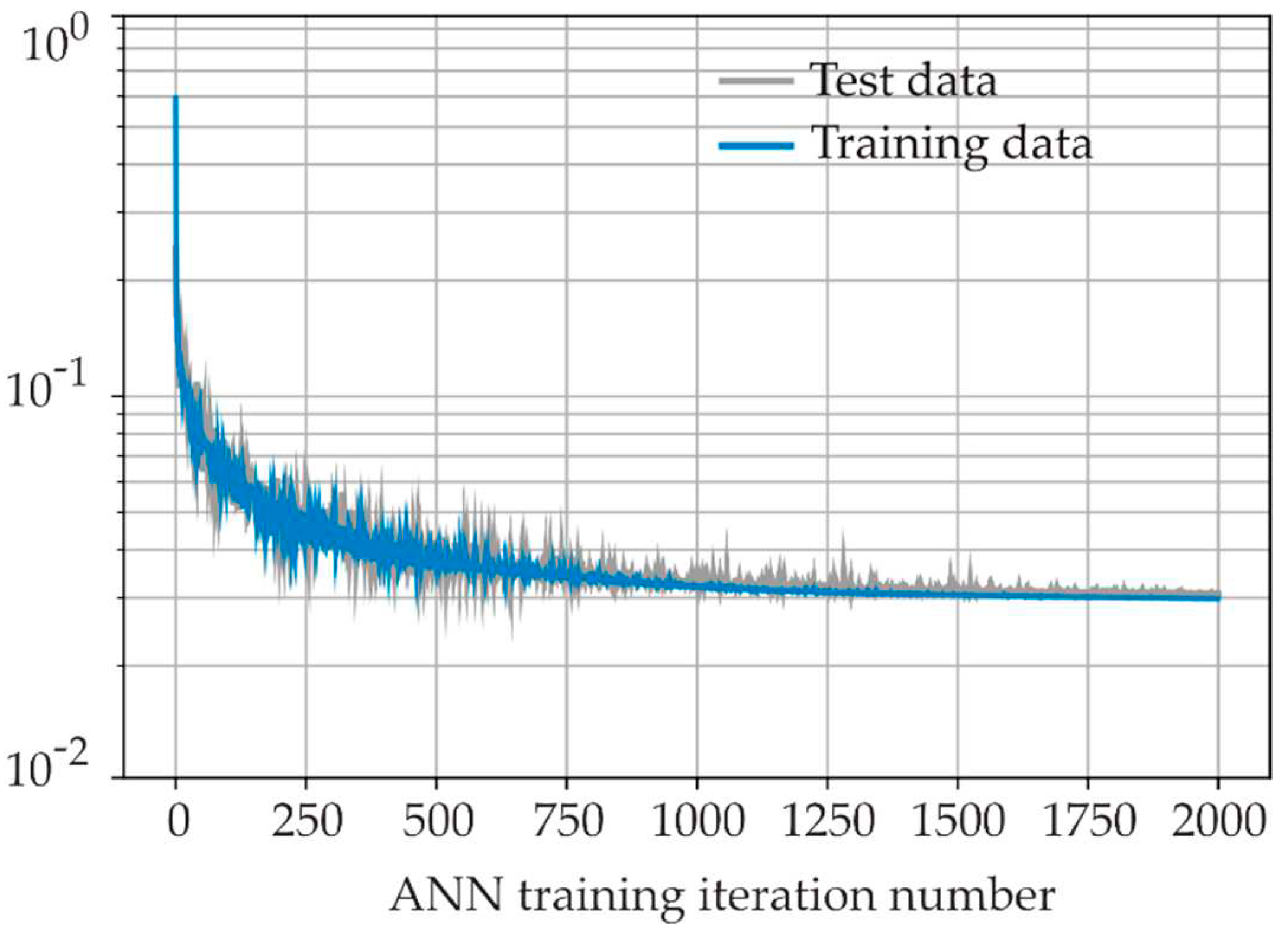
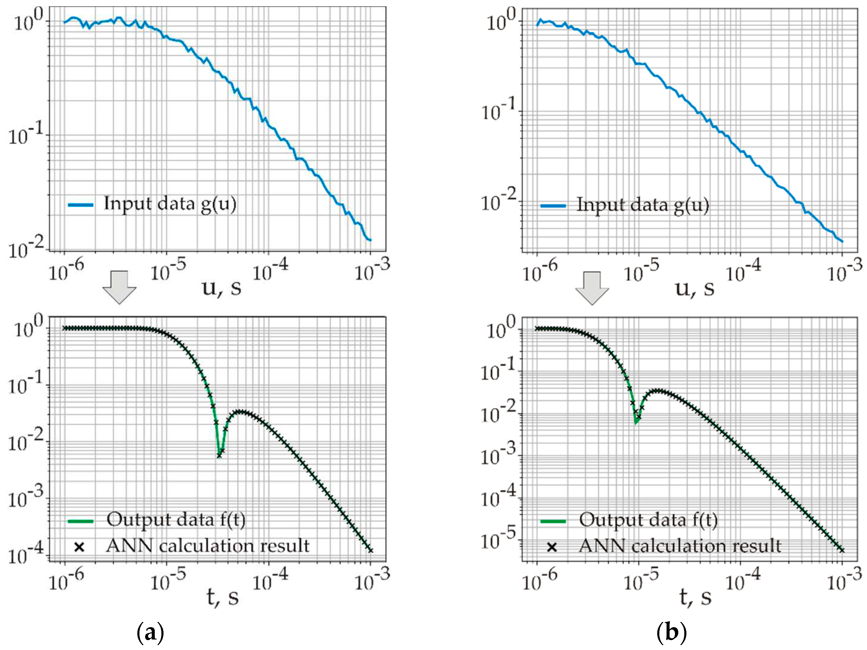
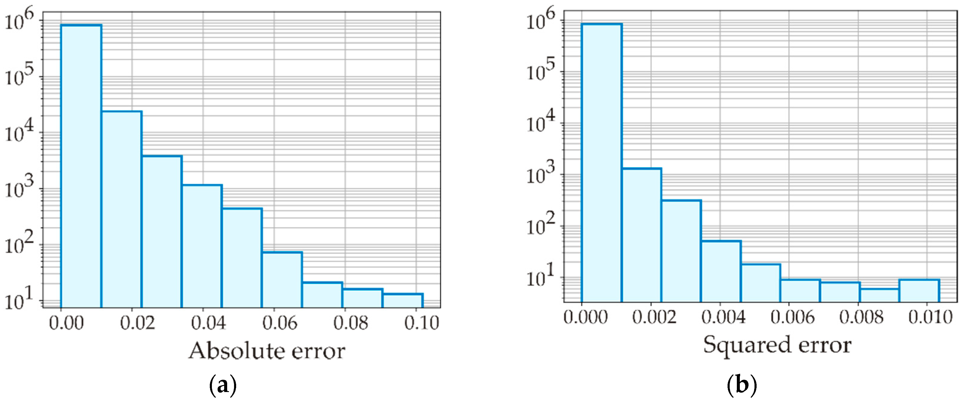
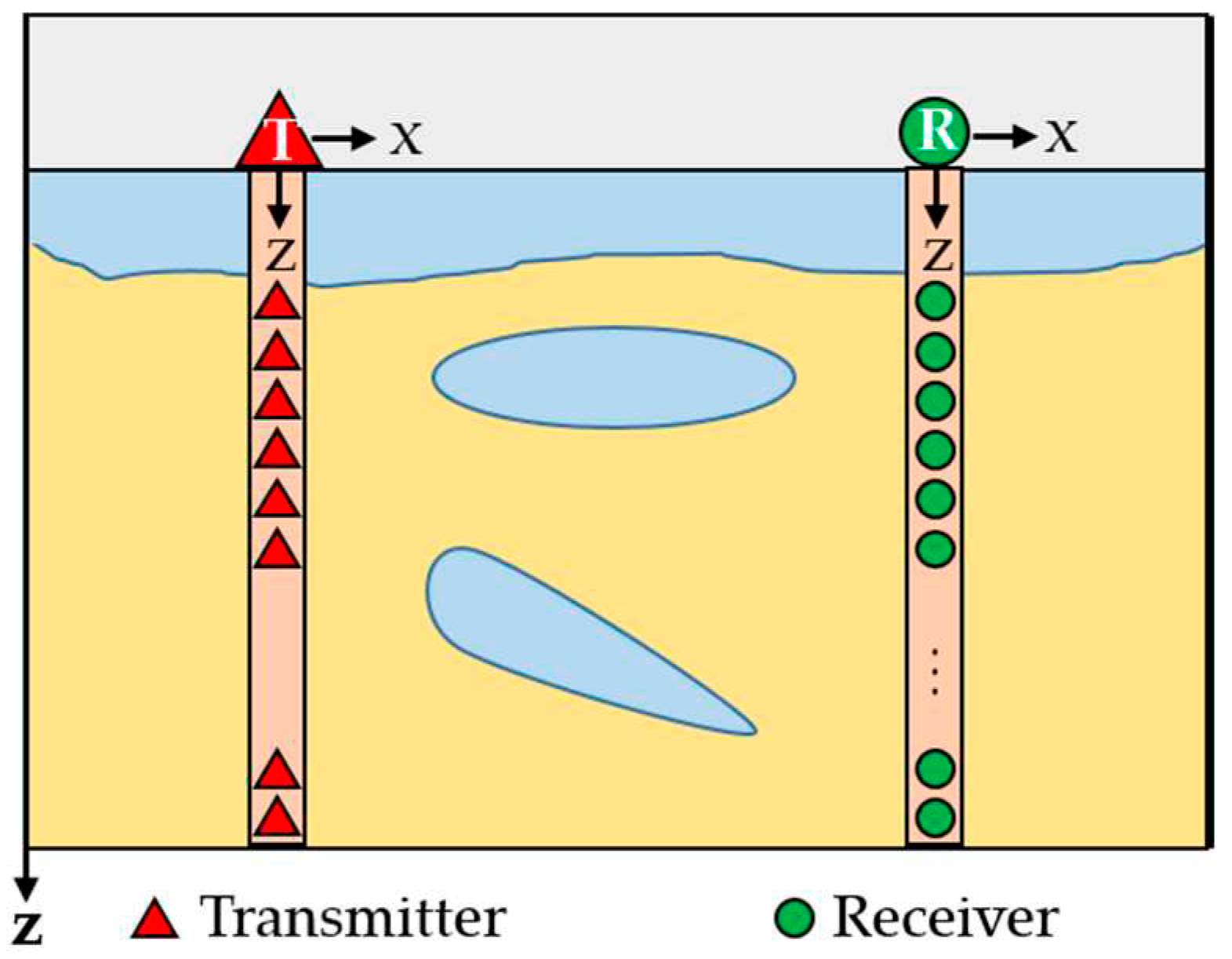
| Cost function | Result (training data) | Result (test data) |
|---|---|---|
| Mean absolute error | 1.6·10-3 | 1.8·10-3 |
| Mean squared error | 1.4·10-5 | 2.0·10-5 |
Disclaimer/Publisher’s Note: The statements, opinions and data contained in all publications are solely those of the individual author(s) and contributor(s) and not of MDPI and/or the editor(s). MDPI and/or the editor(s) disclaim responsibility for any injury to people or property resulting from any ideas, methods, instructions or products referred to in the content. |
© 2024 by the authors. Licensee MDPI, Basel, Switzerland. This article is an open access article distributed under the terms and conditions of the Creative Commons Attribution (CC BY) license (http://creativecommons.org/licenses/by/4.0/).


