Introduction
Aviation agencies are pushing manufacturers and operators to improve aircraft effectiveness by reducing lift-induced drag as well as the vortices created during flight by the introduction of a wingtip devices. A winglet is a wing-like structure set at an angle at the tip of the wing designed to reduce vortices generated alongside the surface of the wing by reducing the pressure gradient at the tip of the wing, hence reducing the magnitude of the vortices generated during flight.
The motivation of this research has been to explore three designs of winglets and without winglet on varying cross-sectional areas, effectiveness of wingtip considerations, measured effects of such surfaces on extreme aerodynamic forces and their design considerations.
In the late 1800s, British aerodynamicist Frederick W. Lanchester created the idea of winglets, he patented an idea that a vertical surface (end plate) at the wingtip would reduce drag by controlling wingtip vortices. Langevin, G.S and Overbey, P (2003). Unfortunately the concept never demonstrated its effectiveness in practice because the increase in drag due to skin friction and flow separation outweighed any lift-induced drag benefit. Long after Frederick W. Lanchester, engineers at NASA Langley Research Centre inspired by an article in Science Magazine on the flight characteristics of soaring birds and their use of tip feathers to control flight, continued on the quest to reduce induced drag and improve aircraft performance and further develop the concept of winglets in the late 1970s. Bargsten, C. J. And Gibson, M. T. (2011). This project provides a fundamental knowledge and design approach for a promising option to improve aerodynamic efficiency of the Boeing 737, by reducing lift induced drag.
The Boeing Company originally developed the canted winglet in the middle of the 1980s in an effort to extend the range and payload of their wide-body 747-400 passenger and freight models. The lift/drag ratio actually increased by 4% as a result of the improvement. This was far more than the top limit of 9% that the ACEE program's wind tunnel research had recommended, with a significant portion of the increase coming from the longer effective wing span. M. Molnar (2012).
However, The cant angle, or the angle between the winglet's plane and the wing, cannot be reduced too much since doing so alters the wing's properties at higher angles of attack. Decreased cant angle makes it easier for the flow to separate and produces stronger vortices to develop at the tip section, which reduces the effectiveness of the winglet. Committee on Assessment of Aircraft Winglets for Large Aircraft Fuel Efficiency, (2007).
The "fence" design is Airbus' answer to Boeing's canted winglets. It was also adopted in the middle of the 1980s with the intention of reducing the total fuel consumption of its aircraft. Wingtip fence gets its name from the fact that, in contrast to canted designs, the winglets are frequently perpendicularly linked to the wingtips and have cross sections that are double-sided. DjahidGueraiche et-al (2017).
The blended winglet consists of an upward swept extension of the wing. Compared to many other types, the blended winglet features a smooth chord transition instead of an angular transition from the wing to the winglet. Significant improvements of the lift/drag-ratio, up to almost 9%, can be seen even at very simple, non-optimized implementations of the design. Nicolas El Haddad, (2015). The design was initially investigated by Boeing in the mid-80s and further developed by Aviation Partners Inc in the early 90s. It was standard on Boeing Business Jet series but is also available on the 737-, 757- and 767-series. Boeing claims the use of blended winglets gives a decrease in fuel burn in the range of 4 to 5%. Zabihollah Najafian (2014).
The spiroid type of winglet is, like the name suggests, a loop of a rigid ribbon. The design was first patented by Louis B. Gratzer in 1992, with claims of superior performance in reducing the lift induced drag. William Freitag, et-al (2020). If designed correctly, the effects of the wingtip vortices can be reduced significantly. Research has shown that the two vortex cores (formed due to low pressure regions at the bends of the spiroid), may combine into a single vortex. This single vortex follows a straight path behind the wing and does not cause negative interaction with the other parts of the fuselage, which in turns improves the range of the aircraft. Gautham Narayan, et-al (2016). Spiroid winglets may also provide increased benefits at takeoff, as research has shown an increased lift coefficient at stall angles. Suhail Mostafa, et-al (2014). The design was first tested on the Gulfstream II in 1993, and later refined and tested on the Falcon 50 in 2010. Aviation Partners Inc are further investigating the design and technology for new implementation on a wide variety of jets. Ali Murtaza, et-al (2017).
More development has been made by combining two or more of the above types of winglets to produce combined characteristics of the concerned winglets and then improve the efficiency of an aircraft by reducing a significant amount of lift-induced drag.
A type of wingtip device, similar to a three-way hybrid between a blended winglet, wingtip fence, and raked wingtip, is used by the Boeing 737 Max. Boeing asserts that this new design will improve fuel efficiency by 1.5% over the 10-12% improvement already expected for the 737 Max. G. S. Langevin and P. Overbey (2003).
Methodology
During the course of the research, the sequential steps to performing analysis of the different types of winglets on the boeing 737 with aid of computer aided design (CAD) software SOLIDWORKS for both design and simulation. The following steps are;
Geometric data collection on various winglet design (canted, blended and fenced)
Computational design and assembly of boeing wing alongside with various wingtips using solidworks
Run aerodynamic simulations on each prototype
Result analysis of the prototype
Compare the results of the three (3) prototype
Conclusion
Description of the Model
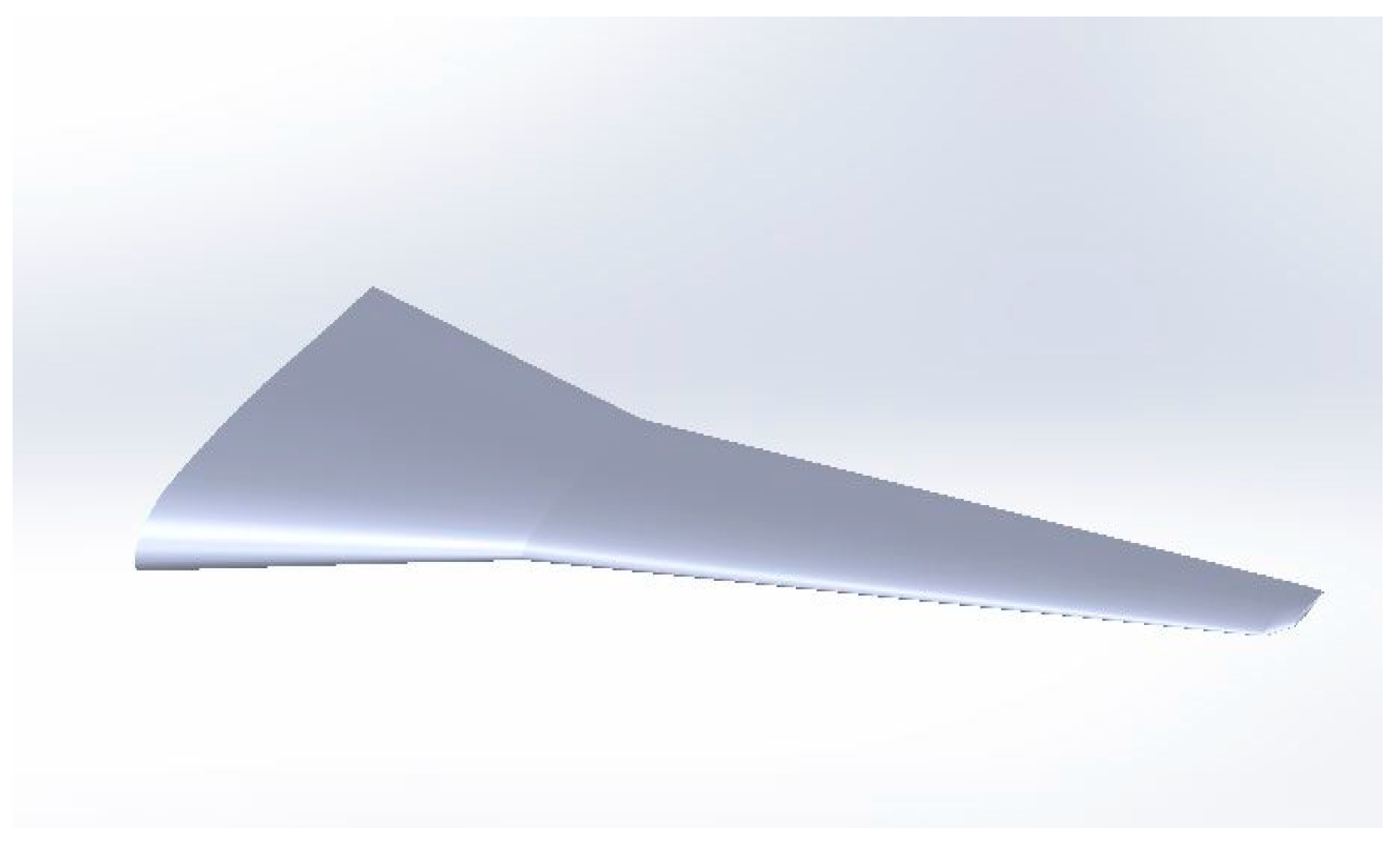
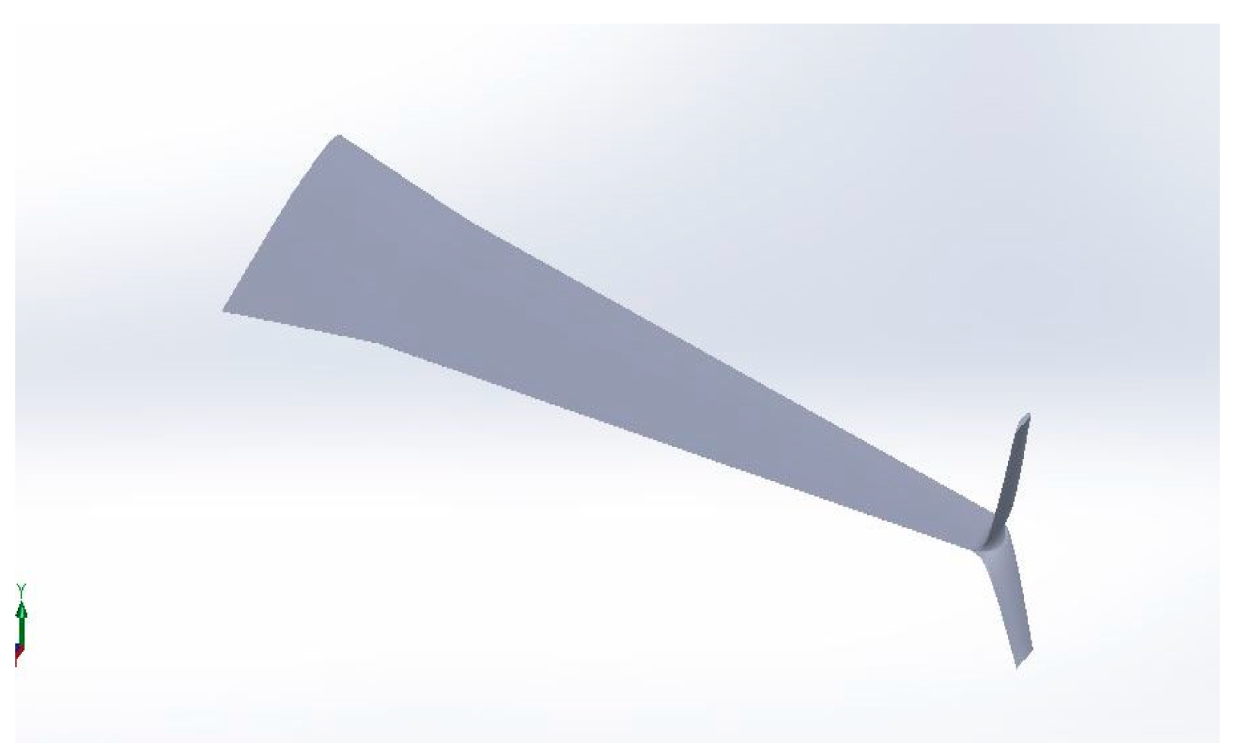
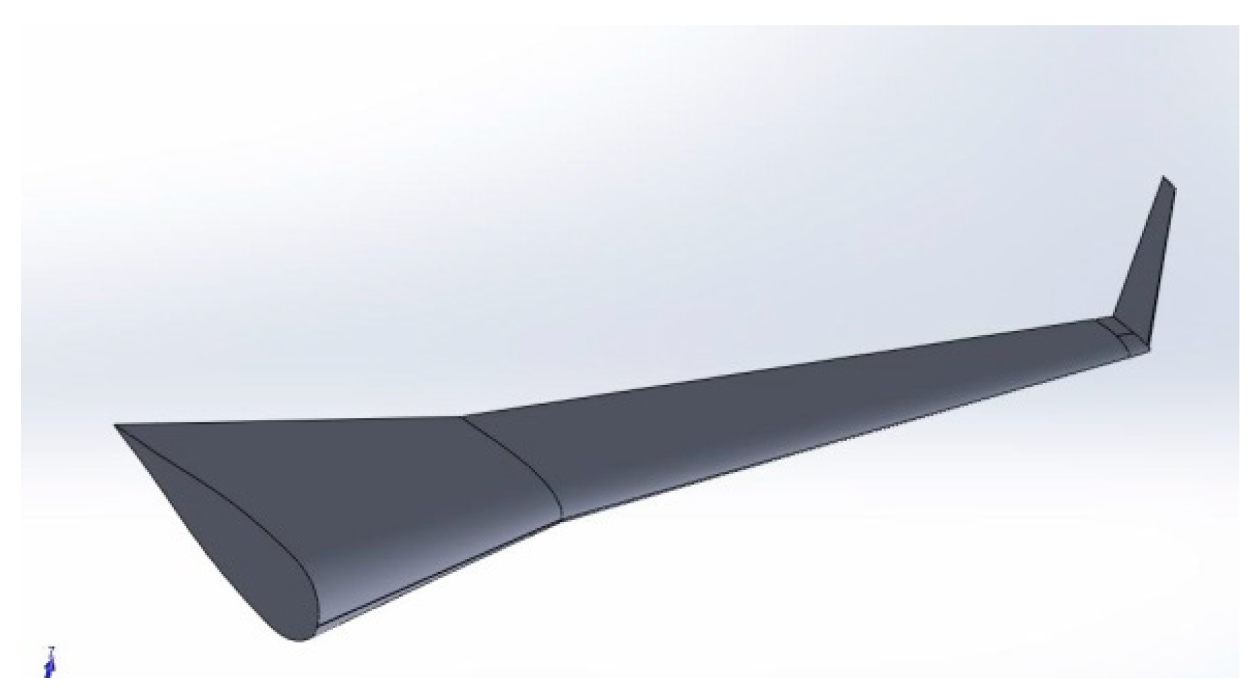
Figure 2 shows a Geometric (3-D CAD Modelling) of the wing-winglet configurations designed using solidworks following the Boeing737-800 specification. The aerofoil used according to the Boeing737 specification for mid-wing section NACA 22112.
Figure 2.
Fenced Winglet Geometry.
Figure 2.
Fenced Winglet Geometry.
Figure 3.
Canted Winglet Geometry.
Figure 3.
Canted Winglet Geometry.
3.2. Computational Domain
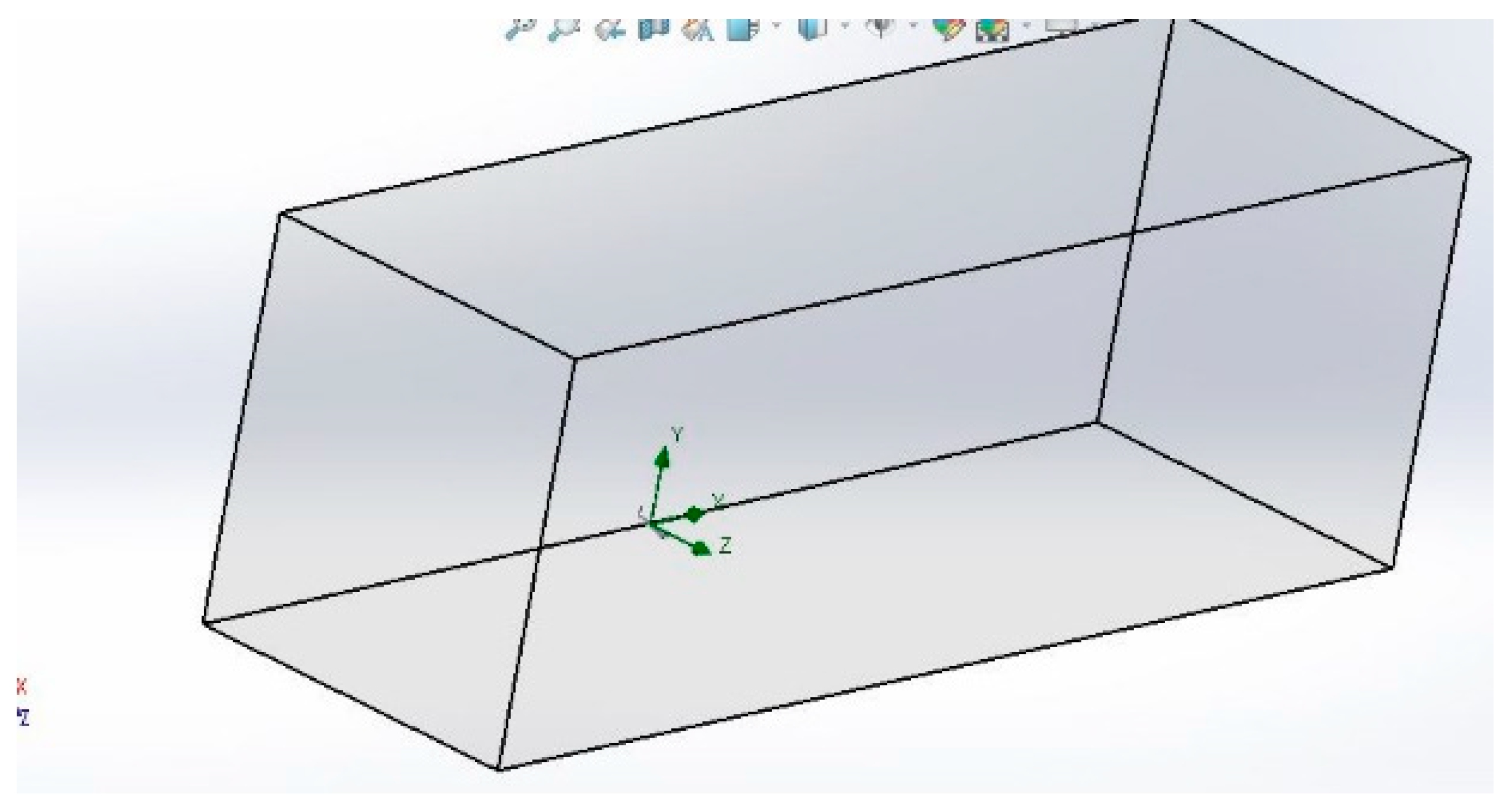
Wing model’s rectangular domain is used as shown below, below is the domain for a blended winglet design.
Figure 4.
Blended Winglet In A Domain.
Figure 4.
Blended Winglet In A Domain.
3.2. Mesh Generation
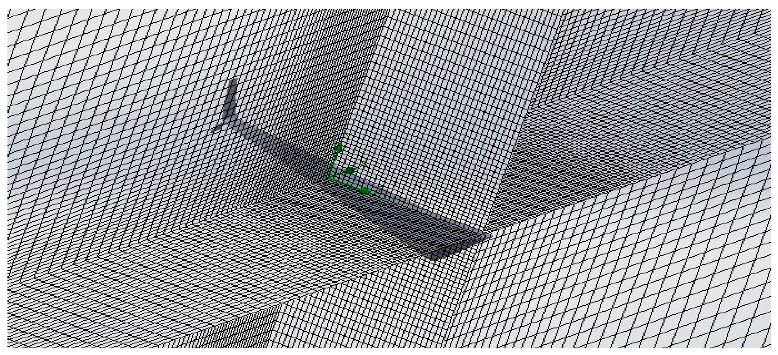
The mesh generated is Unstructured tetrahedral mesh because its ability to mesh easily for complex geometry and Arbitrary positions. The mesh has been refined around the aerofoil, with additional refinement around the leading and trailing edges, while the mesh in the rest of the computational domain is coarse. In addition, values for Inflation layer thickness, Inflation layer number, and base size have been defined. The meshing of the 3D computational domain is performed with the tools available for computations as well as time constraints in mind. Mesh refinement was achieved using three separate mesh refinement choices. The base size is based on the approximate cell size calculation on the wing surface. The maximum cell size is defined as the largest distance on the surface of the computational domain in the ‘Inlet' upstream region. The mesh of the computational domain is shown in below Figures.
Figure 5.
Fenced Winglet Design With Mesh.
Figure 5.
Fenced Winglet Design With Mesh.
3.2. Boundary Conditions and Goals
3.2.1. Boundary Conditions
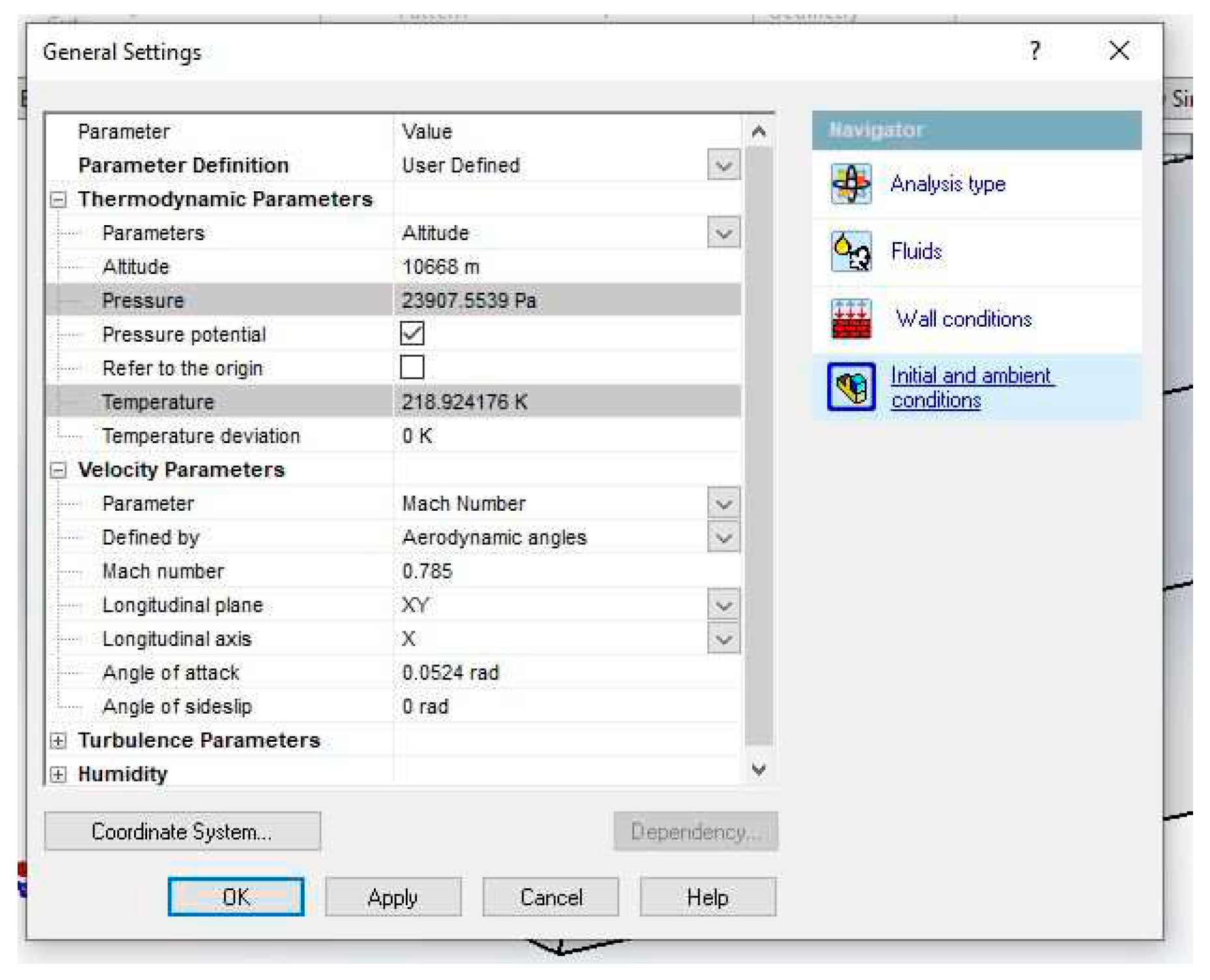
After the mesh generation for the fluid flow and wing was completed, the solver performed a numerical simulation. The boundary condition, solution control parameters, and material properties were determined when the turbulence model was selected. The model was initialized with inlet values and all the parameters were specified for various attack angles. The computation for the flow parameters was then performed several times.
Figure 6.
Boundary Conditions.
Figure 6.
Boundary Conditions.
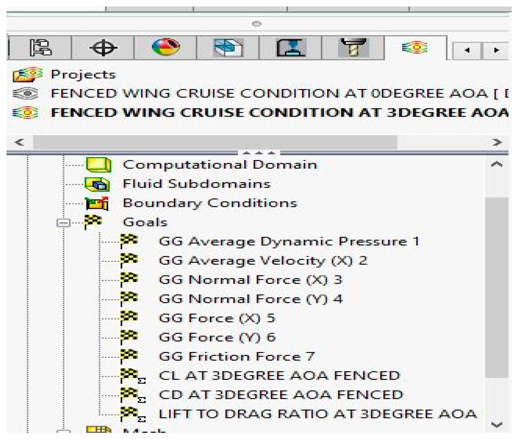
Figure 7.
Goals And Custom Goals.
Figure 7.
Goals And Custom Goals.
| Density (ρ) |
|
| Viscosity |
|
| Mach number (M) |
0.785 |
| Pressure (P) |
101325Pa |
| Altitude (h) |
10668m |
3.2.1. Goals
The goals that would be indicated in our simulation would be “coefficient of lift”, which during our simulation would be referred to as the “normal force Y” since there is no such property like coefficient of lift in SOLIDWORKS simulation. So the goals are; Coefficient of Lift (C
L), Coefficient of Drag (C
D), and the Lift-to-Drag ratio (L/D).
Results and Discussions
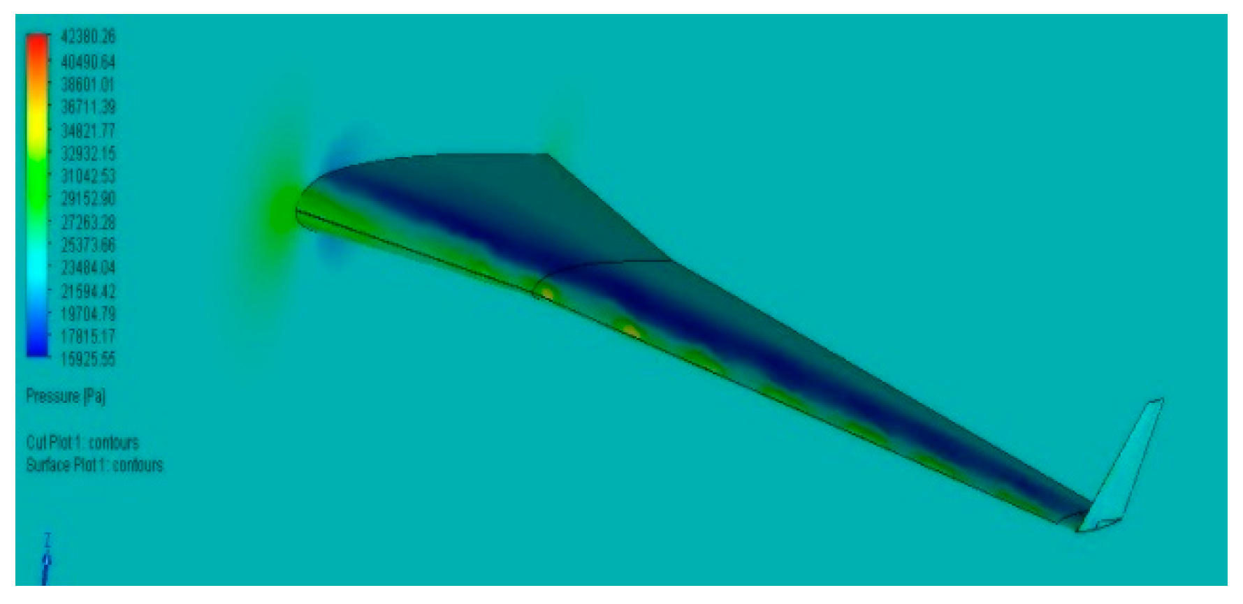
The results of the 3D wing with each winglet modeled was compared to each other, including the wing with no winglet. The discussion is focused on the aerodynamic characteristics which include drag coefficient (CD), lift coefficient (CL), and lift-to-drag ratio (L/D). The pressure coefficient contours and path lines will also be observed and studied. The simulation was carried out at various angles of attack, α, and Mach number 0.785.
4.1. Pressure field behind wing
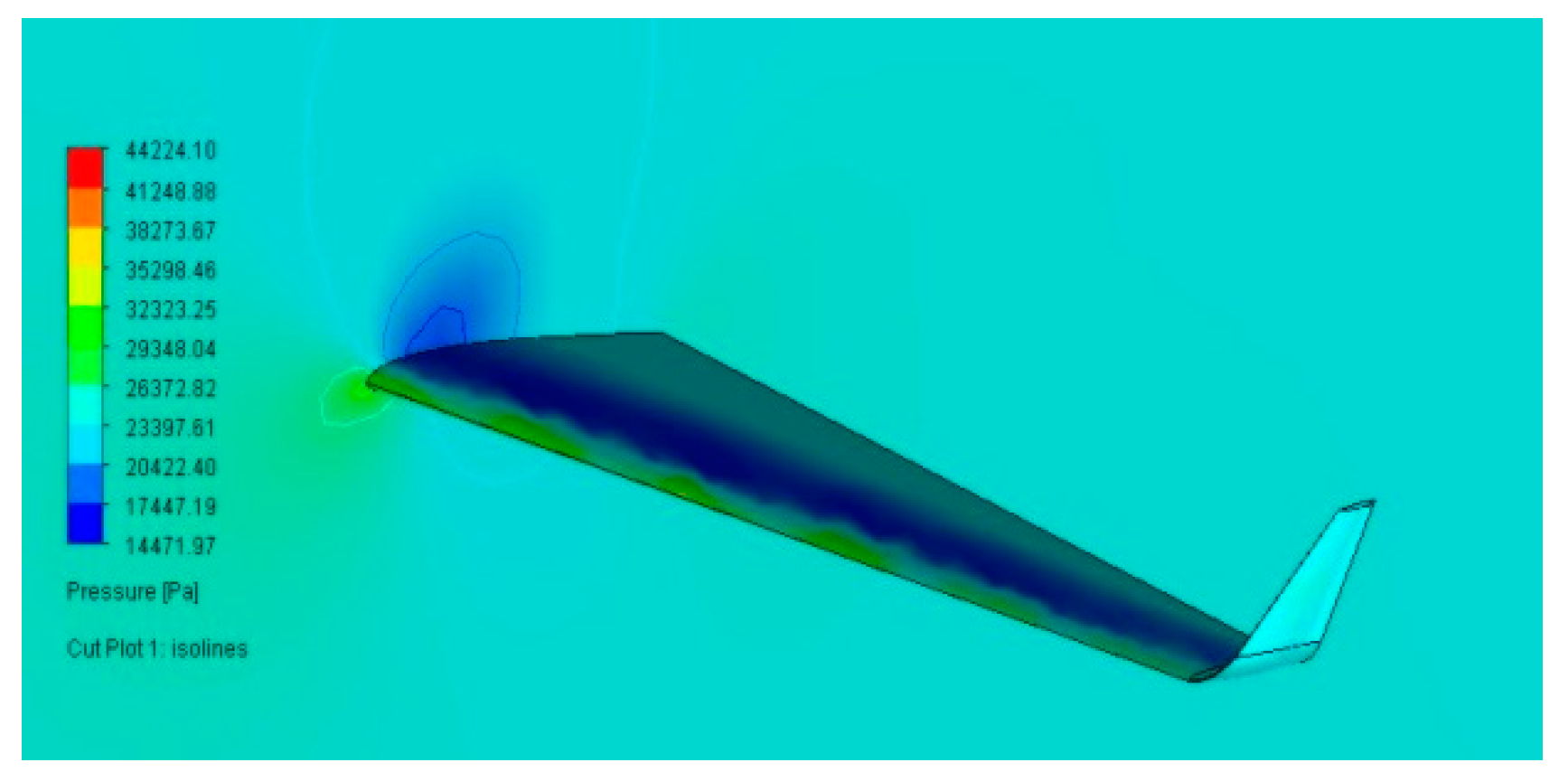
The calculated pressure field is shown in Figure 4a,b in a plane perpendicular to the free stream, three wing tip chord lengths below the wingtip without and with winglets. The wing tip vortex's strength and location can be seen. The vortex creates lower pressure where it generated, which suggests high local velocities, as shown in the accompanying figures. As seen in Figure 4a, a wing without a winglet creates a stronger vortex than any other wing that has a winglet, which results in a higher induced velocity and more drag.
Figure 4.
(a) Pressure intensity for wing. (b) Pressure intensity for fenced winglet.
Figure 4.
(a) Pressure intensity for wing. (b) Pressure intensity for fenced winglet.
Figure 8.
Pressure intensity for canted winglet.
Figure 8.
Pressure intensity for canted winglet.
Figure 9.
Pressure intensity for blended winglet.
Figure 9.
Pressure intensity for blended winglet.
4.2. Aerodynamic characteristics
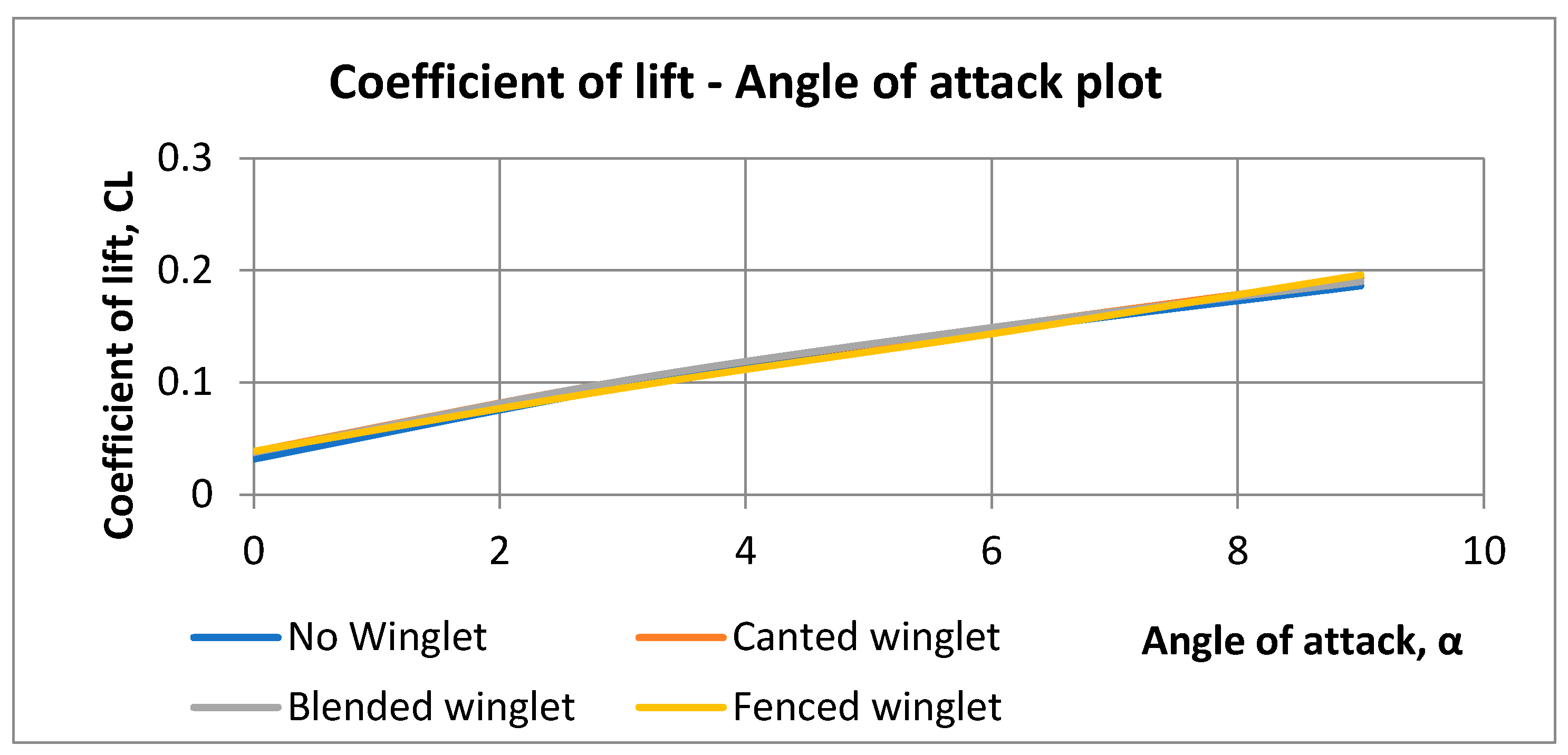
Lift and drag both increases with an increase in the angle of attack. The strength of the wing tip vortices increases with increased lift, increasing the airplane's induced drag. We lessen the force of these vortices and the resulting drag by using a winglet. The performance during takeoff and landing, where this results in a reduction in required runway length, might benefit greatly from this performance enhancement. By obtaining a faster rate of ascent, these aerodynamic structures help boost climb performance.
Figure 10.
Coefficient of lift to Angle of attack plot.
Figure 10.
Coefficient of lift to Angle of attack plot.
Figure 11.
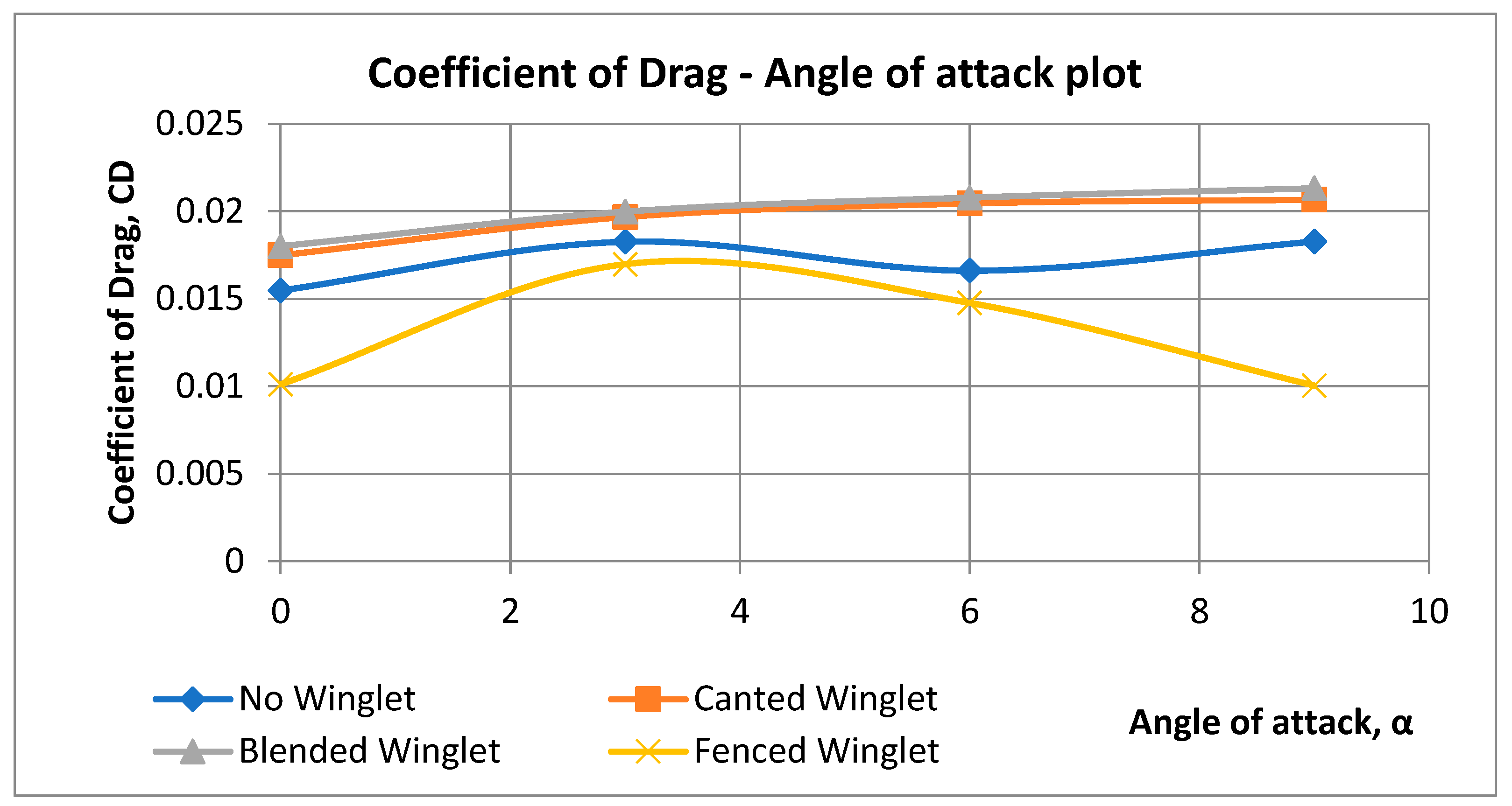
Coefficient of drag to Angle of attack plot.
Figure 11.
Coefficient of drag to Angle of attack plot.
Figure 12.
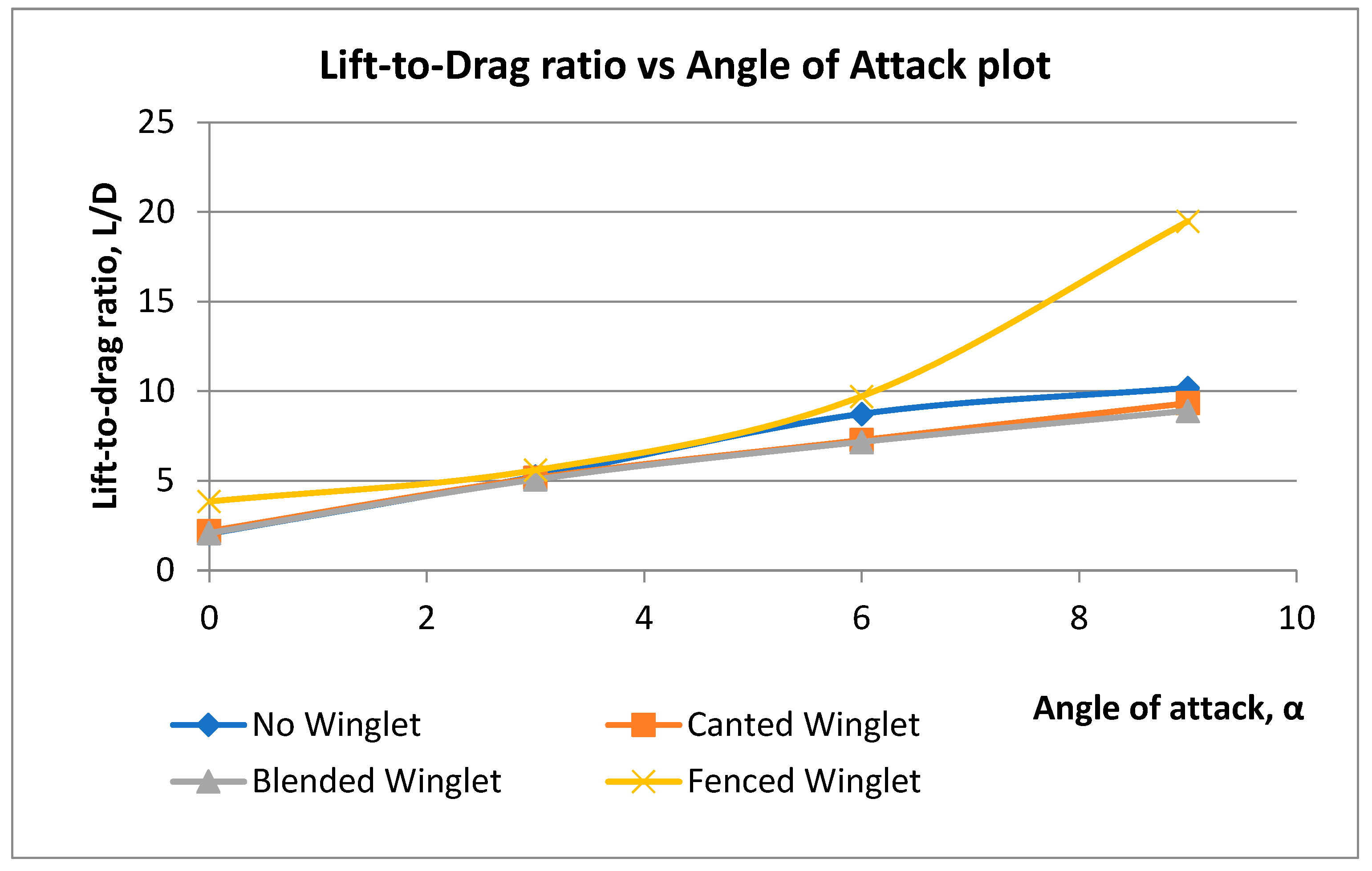
Coefficient Of Lift To Angle Of Attack Plot.
Figure 12.
Coefficient Of Lift To Angle Of Attack Plot.
It is observed that the coefficient of lift (C
L) increases with an angle of attack (α) as shown in Figures 4 and
5.
The result for the coefficient of drag (C
D) is slightly different, the C
D increases with an increase in angle of attack as shown in Figures 4 and
6. The course changed for aircraft wing without winglet whereby the coefficient of drag dropped from 0.018 to 0.016 at 6
0 angle of attack, α and then rises at 9
0 angle of attack. The case is also different for a fenced winglet, the coefficient of drag reduced from angle of attack 3
0. This shows how efficient the fenced wingtip device is compared to other winglets.
Figures 4 and
7 shows the lift-to-drag ratio of different wingtip devices at different angle of attack. The Fenced winglet design proved to give a promising efficiency at higher angle of attack compared to other wingtip devices and wing without winglet. Increasing the angle of attack increases the lift-to-drag ratio.
Conclusion
The results that were obtained after the simulation on each configuration showed that wing with fenced winglet has the highest value of Lift coefficient (CL) and Lift-to-Drag ratio (L/D) as compared to other wings. It proved that the fenced winglet will perform better than the blended winglet which is the original wingtip device used on Boeing737-800 aircraft wing.
Table of Parameters
| Parameter |
Meaning |
| ρ |
Density ( |
|
Viscosity ( |
| P |
Pressure |
| h |
Altitude |
| L |
Lift |
| D |
Drag |
| V |
Velocity ( |
| M |
Mach Number (dimensionless) |
| S |
Surface Area |
| CL
|
Coefficient of Lift |
| CD
|
Coefficient of Drag (dimensionless) |
| L/D |
Lift-to-Drag Ratio (dimensionless) |
|
Angle of Attack (degree) |
References
- Faye, R., Laprete, R. and Winter, M., Blended Winglets, Aero, No. 17,. Boeing, 2002.
- Chambers, J. R. Concept to reality: Constributions of NASA Langley Research Center to U.S. Civil Aircraft of the 1990s (Washington, DC: NASA SP-2003-4529,2003.
- Langevin, G. S. and Overbey, P., To reality: Winglets, NASA Langley Research Center, October 17, 2003.
- Bargsten, C. J. And Gibson, M. T. ; NASA Inovation in Aeronautics: Selected Technologies That Have Shaped Modern Aviation, NASA TM/2011-216987, 2011.
- Molnar, M. Boeing Says Radical New Winglets on 737 X Will Save More Fuel/ NYC Aviation. Retrieved 3 May 2012.
- Committee on Assessment of Aircraft Winglets for Large Aircraft Fuel Efficiency, 2007,assessment of wingtip modifications to increase the fuel efficiency of air forceaircraft, https://www.nap.edu/read/11839/chapter/5#33, 2007, 2020-05-1.
- DjahidGueraiche, Sergey Popov, Moscow Aviation Institute, 2017, Winglet Geometry Impact onDLR-F4 Aerodynamics and an Analysis of aHyperbolicWingletConcept,https://www.researchgate.net/publication/321846721_Winglet_Geometry_Impact_on_DLRF4_Aerodynamics_and_an_Analysis_of_a_Hyperbolic_Winglet_Concept,December 2017, 2020-05-11.
- Corporate information - Innovation & technology. Airbus. http://www.airbus.com/en/corporate/innovation/, 2009-04-21.
- Nicolas El Haddad, 2015, Aerodynamic and Structural Design of a Winglet for Enhanced Performance of a Business Jet,https://commons.erau.edu/cgi/viewcontent.cgi?Article=1264&context=edt, May 2015, 2020-05-11.
- ZabihollahNajafian Ashrafi, Ahmad Sedaghat, 2014, Improving the Aerodynamic Performance ofa Wing with Winglet, 2014, https://www.researchgate.net/publication/272175209_Improving_the_Aerodynamic_Performance_of_a_Wing_with_Winglet, November 2014, 2020-05-11.
- William Freitag, E. Terry Schulze, Boeing, 2009, Blended Winglets Improve Performance,https://www.boeing.com/commercial/aeromagazine/articles/qtr_03_09/article_03_1.html,2009, 2020-04-29.
- Gautham Narayan, Bibin John, 2016, Effect of winglets induced tip vortex structure on theperformance of subsonic wings,https://www.sciencedirect.com/science/article/abs/pii/S1270963816305569, September 2016,2020-05-11.
- Suhail Mostafa, Shyam Bose, Archana Nair, Mansoor Abdul Raheem, Thasneem Majeed, AtiqurMohammed, Young Kim, 2014, A parametric investigation of non-circular spiroid winglets, https://www.researchgate.net/publication/262948452_A_parametric_investigation_of_noncircular_spiroid_winglets, 2014, 2020-05-11.
- Ali Murtaza, Dr. Khalid Parvez, Hanzala Shahid, Yasir Mehmood, 2017, design andcomputational fluid dynamic analysis of spiroid winglet to study its effects onaircraft performance, https://www.irjet.net/archives/V4/i12/IRJET-V4I12239.pdf,December 2017, 2020-05-11.
|
Disclaimer/Publisher’s Note: The statements, opinions and data contained in all publications are solely those of the individual author(s) and contributor(s) and not of MDPI and/or the editor(s). MDPI and/or the editor(s) disclaim responsibility for any injury to people or property resulting from any ideas, methods, instructions or products referred to in the content. |
© 2024 by the authors. Licensee MDPI, Basel, Switzerland. This article is an open access article distributed under the terms and conditions of the Creative Commons Attribution (CC BY) license (http://creativecommons.org/licenses/by/4.0/).
