1. Introduction
Usually the shear effect on the displacements and stresses were more considered in the thick thickness materials than in the thin one under every external loads. Some papers of functionally graded materials (FGMs) were investigated usually including the shear effect. Abouelregal et al. [
1] in 2023 applied the Laplace transform and decoupling techniques to study the thermal vibration of spinning FGM isotropic piezoelectric rod. The effecting numerical results for non-homogeneous index in the displacement, temperature, electric potential and thermal stress were presented. The thermal stress variation was found in one of the most significant results want to be considered. In 2023, Tang et al. [
2] used the radial integral boundary element method (RIBEM) to study the FGM plate under thermal shock loading. The numerical results of displacement, temperature and thermal stress were presented in the thick FGM plate. In 2022, Chen et al. [
3] used the Rayleih–Ritz energy method with the first-order shear deformation theory (FSDT) of displacement models to investigate the vibration of FGM stepped cylindrical shell coupled with annular plate under thermal environment. The temperature-dependent constituent materials SUS304 and Si
3N
4 were used to study the transient responses of displacements. In 2022, Ramteke et al. [
4] presented a nonlinear eigen- frequency responses with the higher-order shear deformation theory (HSDT) of displacement models for porous FGM shell panel under thermal environment by using the finite element method (FEM). In 2021, Saeedi et al. [
5] applied differential quadrature (DQ) method to study the stresses distributions of thick FGM cylindrical shell with aluminum and silicon carbide under internal pressure and thermal loadings. In 2022, Gee and Hashemi [
6] used the dynamic finite element (DFE) method to investigate the numerical results of natural frequencies for the FGM beams. In 2019, Khoshgoftar [
7] used the virtual work principle and second-order shear deformation theory (SSDT) of displacement models to obtain the numerical displacement results of axis-symmetric thick FGM shells under non-uniform pressure. In 2019, Trinh and Kim [
8] presented the nonlinear stability of moderately thick FGM sandwich shells supported by elastic foundations under thermo-mechanical loadings by using the Bubnov–Galerkin procedure, harmonic balance principle and FSDT of displacement models. The numerical solutions for thermal buckling load are obtained. In 2017, Nejad et al. [
9] presented a review for some models used in the solving methods, elasticity theories and shear deformation theories used for the thick FGM cylindrical and conical shells.
Some generalized differential quadrature (GDQ) computational results with nonlinear displacement third-order shear deformation theory (TSDT), thermal temperature of environment and external heating loads were presented for the thermal vibrations of FGMs. Hong [
10] in 2023 studied the GDQ solutions of thick FGM plates with the effects of TSDT model but not in function of nonlinear coefficient
term of TSDT model. In 2022, Hong [
11] presented the dynamic advanced GDQ solutions of thick FGM plates under thermal vibration with the effects of TSDT and advanced shear factor that was in function of
term of TSDT model, FGM power law index and environment temperature, but not in function of total thickness. Hong [
12] in 2022 presented the GDQ solutions of thick FGM circular cylindrical shells under thermal vibration with the effects of TSDT and varied shear factor that was not in function of
term of TSDT model. Hong [
13] in 2022 studied the advanced GDQ results of thick FGM plates-cylindrical shells under thermal vibration with the effects of TSDT and advanced shear factor that was in function of
term of TSDT model, FGM power law index and environment temperature, but not in function of total thickness of plates-cylindrical shells. The further study now providing the GDQ vibration results of stresses and displacements with the effects of TSDT, advanced varied shear correction coefficient, environment temperature and power law index.
2. Formulation
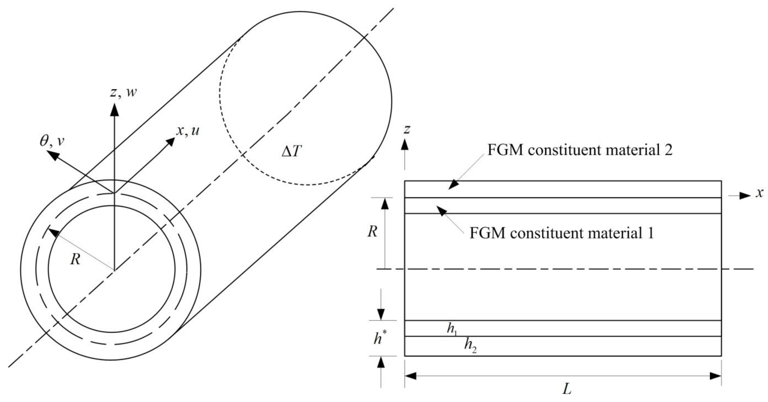
Two constituent material FGM circular cylindrical shell is studied in
Figure 1, in which the parameter of
denotes the inner layer thickness of constituent material 1,
denotes the outer layer thickness of constituent material 2,
L denotes the axial length, and
denotes the total thickness. The material properties in power-law function are studied and parameter of
denotes Young’s modulus in standard variation form of FGMs,
denotes power law index, and
denotes Poisson’s ratios of FGMs that is assumed in the simple average form as follows [
10],
Figure 1.
Two constituent material of thick FGM circular cylindrical shells.
Figure 1.
Two constituent material of thick FGM circular cylindrical shells.
where
and
are the Young’s modulus,
and
are the Poisson’s ratios of the constituent material 1 and material 2, respectively in the FGMs.
The properties
of individual constituent material of FGMs, e.g.,
,
,
and
are in functions of environment temperature
T can be calculated by the following form,
in which
,
,
,
and
are the temperature coefficients.
The time dependent displacement vector
of thick FGM circular cylindrical shells are studied in the nonlinear of
form with nonlinear coefficient
term of TSDT equations [
12,
14] as follows,
where
,
,
,
and
, in which
denotes the time,
u and
v denote respectively the tangential displacements in the direction of
x and
axes.
and
denote respectively the tangential displacements in the direction of
x and
axes,
w denotes the transverse displacement in the direction of
z axis in the middle-plane of FGM shells.
and
denote the shear rotations.
R denotes the radius of middle-surface in FGM shells. The superscript t is operating the transpose of vector.
The stress vector
in the thick FGM circular cylindrical shells under external heating loads with temperature difference
for the
kth constituent layer are studied in the following equations [
15],
where
,
,
and
in which
and
are the normal stresses,
and
are the shear stresses.
and
are in-plane strains,
and
are shear strains can't negligible for thick shells.
and
are thermal expansion coefficients,
is the thermal shear coefficient.
with subscripts
i,
j=1,2,4,5 and 6 are the stiffness of FGM shells.
The advanced varied shear correction coefficient
can be used as a coefficient in the following stiffness
integral equations
,
,
,
,
,
and
,
,
,
,
,
with subscripts
=4,5 when
and
can't negligible in thick shells, also for subscripts
=1,2,6 when
and
are applied.
where simple forms of
and
are used in the following with
z/
R term cannot be neglected [
16],
,
,
,
and
.
And the advanced
expression can be derived and expressed in the following equation by using the total strain energy principle to apply [
11],
in which
,
with parameters
FGMZS,
FGMZSN, FGMZI, FGMZIV1 and
FGMZIV2 are in functions of
,
,
and
. The calculated values of nonlinear advanced
are usually functions of
,
and
T.
The
time dependent expression can be studied between the FGM shell and curing area under external heating loads by using the following equation in linear of
z,
where temperature parameter
, also the simple form heat conduction equation in cylindrical axes is used in the following [
10],
in which
,
denotes the thermal conductivity of FGMs,
denotes the density of FGMs,
denotes the specific heat of FGMs, they are all assumed in the simple average property form of constituent material 1 and 2, e.g.,
with
is density of FGM constituent material 1 and 2, respectively.
The dynamic equations of motion in the thick FGM cylindrical shells with TSDT are given in the following that can be derived by using the generalized Hamilton total energy principle [
13],
where
,
, subscripts
,
,
,
,
,
,
q is external pressure load,
, (
i= 0, 1, 2,…,6), with
denotes the constituent layers total number,
denotes the density of superscript
k th constituent layer,
, in which subscript
i=1, 4 and
. And assumed strain-displacement relations with
,
and
are used as follows,
Substitute eqs. (3) and (7) into eq. (6), the dynamic equilibrium differential equations in the cylindrical coordinates of thick FGM circular cylindrical shells in terms of partial derivatives of
with TSDT under partial derivatives of external loads can be written in matrix forms as follows [
13].
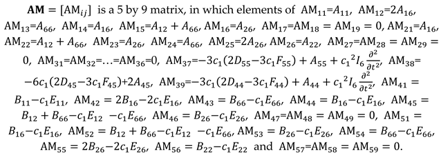
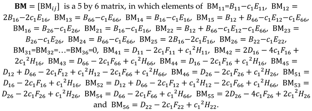
where
is a 5 by 5 matrix,
is a 5 by 12 matrix,
is a 5 by 8 matrix,
is a 5 by 9 matrix,
is a 5 by 6 matrix,
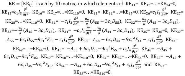
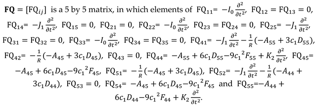
is a 5 by 10 matrix,
is a 5 by 5 matrix, for more details of these matrices are expressed in the section
Appendix A.
with
in which
and
are external in-plane distributed forces in
x and
direction respectively.
By using the GDQ numerical method to solve the equation (8) for the thick FGM circular cylindrical shells under time sinusoidal vibrations of displacement, shear rotations and thermal temperature difference of external heating loads only, i.e.,
are studied as follows,
where
denotes the natural frequency with subscripts
m,
n denote the mode shape numbers of FGMs,
denotes the applied heat flux frequency,
denotes the temperature amplitude.
For more detail procedures used in GDQ numerical method can be referred [
10], the GDQ dynamic discrete equations could be obtained and expressed into the matrix equation as follows for a interior grid point at subscripts (
i,
j) in the computation,
in which
denotes the coefficient matrix with dimension of
by
(
) contains (
,
,
,
,
,
and
,
,
,
,
,
) and weighting parameters (
) for the superscript m th-order derivative of the functions, e.g.,
,
,
,
,
,
,
,
,
,
,
,
,
and
with respect to the
x and
directions.
is a
th-order unknown column vector, in which non-dimensional parameters
,
and
are used for column vector
and
is a
th-order row external loads vector, in which
Thus the unknown column vector can be solved and obtained by computer programs. Also the inter-laminar stress in the k th constituent layer could be obtained.
3. Some numerical results
The
and
coordinates for grid
N and
M in the computation of thick FGM circular cylindrical shells are applied as follows to obtain the thermal vibration GDQ results of advanced
with shells constituent layers in (
) under four sides simply supported boundary condition.
The calculated values of frequency
γ of applied heat flux for the thermal loads can be obtained in the heat conduction equation and referred to [
12] for more details. Also the calculated values of vibration frequency
under free vibration (
) can be obtained in the simply homogeneous equation and referred to [
17] for more details.
The FGM constituent material 1 is SUS304 and constituent material 2 is Si3N4 that are applied for the GDQ numerical computations including the effect of advanced varied . The dynamic convergence study of center displacement (mm) in thick FGM circular cylindrical shells is obtained firstly. Secondly, the amplitude of for the thick FGM circular cylindrical shells is calculated. Also the normal stress (GPa) and shear stress (GPa) are computed. Finally, the transient responses of are presented for the thick FGM circular cylindrical shells in the following paragraphs.
3.1. Advanced dynamic convergence study
The advanced dynamic convergence study of in the thermal vibration of nonlinear TSDT of = 0.925925/mm2 and linear of = 0/mm2 for thick FGMs = 10 with = 0.2618004/s and = 5 with = 0.2618019/s, respectively at t= 6s,, = 1.2mm, = 0.6mm, T= 100K, = 100K are presented in Table 1. The convergence values of are calculated with the advanced nonlinear and for three values of . In the nonlinear = 5 case of = 0.925925/mm2: (a) for value of = 0.5, = -0.539419 and = 0.001731/s are obtained. (b) for value of = 1, = -0.922719 and = 0.001733/s are obtained. (c) for value of = 2, = 9.852628 and = 0.001735/s are obtained. In the linear = 5 case of = 0/mm2: (a) for value of = 0.5, = 1.136032 and = 0.002972/s are obtained. (b) for value of = 1, = 1.273499 and = 0.003009/s are obtained. (c) for value of = 2, = 1.317037 and = 0.002994/s are obtained. The error accuracy is 4.4e-06 for the nonlinear amplitude of = 0.5 and = 10. The grid points with = 13×13 are in the very good convergence result for displacement and stress in the advanced thermal vibration of thick FGMs with advanced nonlinear .
Table 1.
Advanced convergence of FGM cylindrical shells with nonlinear varied .
Table 1.
Advanced convergence of FGM cylindrical shells with nonlinear varied .
|
(1/mm2) |
|
GDQ method |
|
(mm) at t= 6s |
|
|
= 0.5 |
= 1 |
= 2 |
| 0.925925 |
10 |
7 × 7 |
|
1.128855 |
1.110114 |
0.460406 |
| 9 × 9 |
|
1.130210 |
1.129728 |
0.460169 |
| 11 × 11 |
|
1.130201 |
1.129750 |
0.460173 |
| 13 × 13 |
|
1.130206 |
1.129744 |
0.460175 |
| |
5 |
7 × 7 |
|
0.085678 |
0.085501 |
0.097189 |
| 9 × 9 |
|
0.085690 |
0.085513 |
0.097174 |
| 11 × 11 |
|
0.085691 |
0.085513 |
0.097172 |
| 13 × 13 |
|
0.085690 |
0.085513 |
0.097164 |
| 0 |
10 |
7 × 7 |
|
20.11788 |
19.25051 |
19.22559 |
| 9 × 9 |
|
3.074959 |
3.096322 |
3.096179 |
| 11 × 11 |
|
3.043667 |
3.072545 |
3.036793 |
| 13 × 13 |
|
3.076776 |
3.077761 |
3.082854 |
| |
5 |
7 × 7 |
|
0.309435 |
0.309401 |
0.312130 |
| 9 × 9 |
|
0.209839 |
0.289099 |
0.290058 |
| 11 × 11 |
|
0.294196 |
0.288990 |
0.289848 |
| 13 × 13 |
|
0.294207 |
0.289000 |
0.289840 |
3.2. Advanced time responses
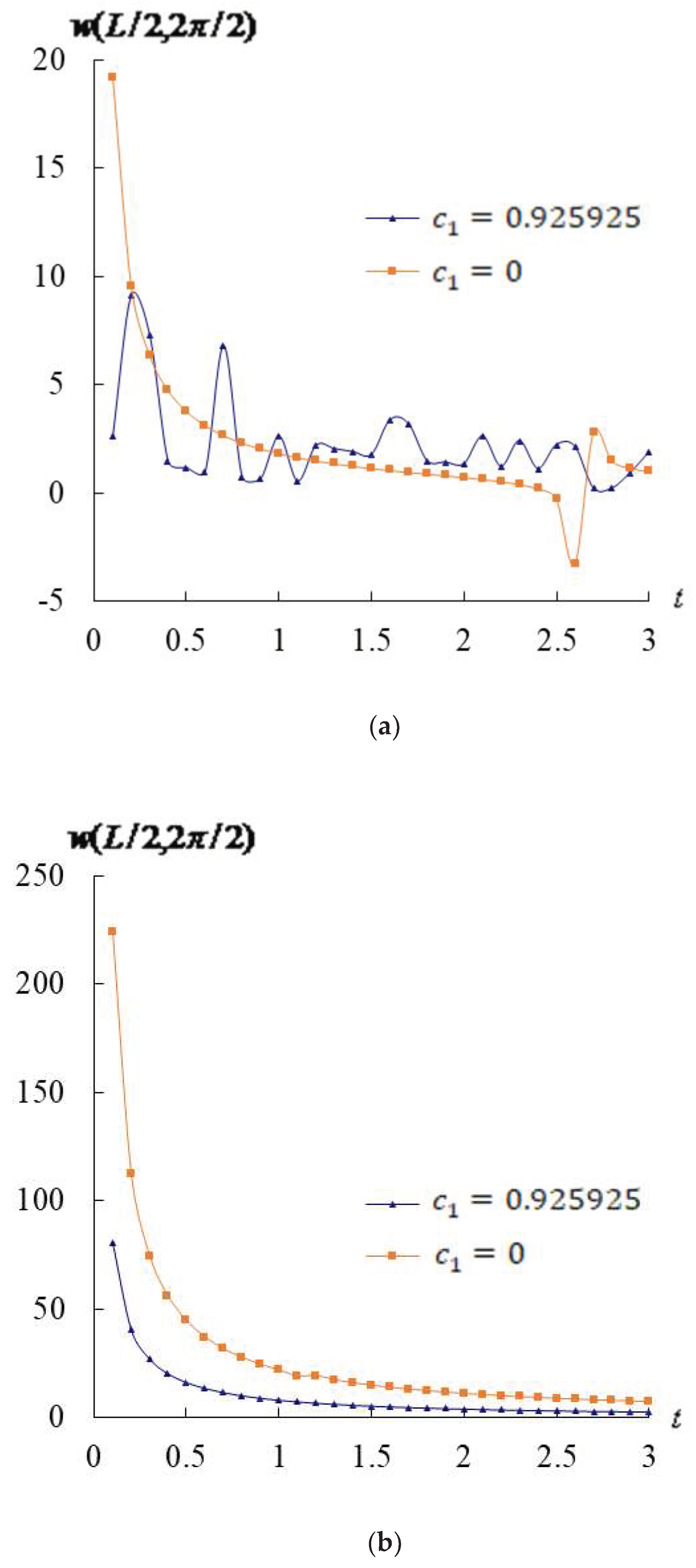
The time responses of advanced are obtained with the advanced nonlinear values. The values are decreasing from =15.707960/s at t =0.1s to =0.523601/s at t =3.0s applied for = 5, and from =15.707963/s at t =0.1s to =0.523599/s at t =3.0s applied for = 10. The response of values versus time t(s) are shown in Figure 2 for nonlinear TSDT case with values = 0.925925/mm2, = -3.535402 and for linear case with values = 0/mm2, = 1.200860 in thick FGMs = 5 and 10, respectively, , T=600K, =100K for t =0.1s-3.0s. The maximum value of is 19.201795mm occurs at t = 0.1s for thick = 5 with = 0/mm2 and = 15.707964/s. The maximum value of is 224.052338mm at t = 0.1s for = 10, = 0/mm2 and = 15.707963/s. The values have the oscillating and decreasing tendencies in the case = 0.925925/mm2, amplitudes are decreasing with time in the case = 0/mm2 except at t= 2.6s for = 5. The values have the converging and decreasing tendencies in the = 0.925925/mm2 and = 0/mm2 for = 10. The values in = 0/mm2 are overestimated and greater than that in = 0.925925/mm2 at the corresponding time for the = 10.
Figure 2.
Advanced (mm) versus t(s): (a) = 5, (b) =10.
Figure 2.
Advanced (mm) versus t(s): (a) = 5, (b) =10.
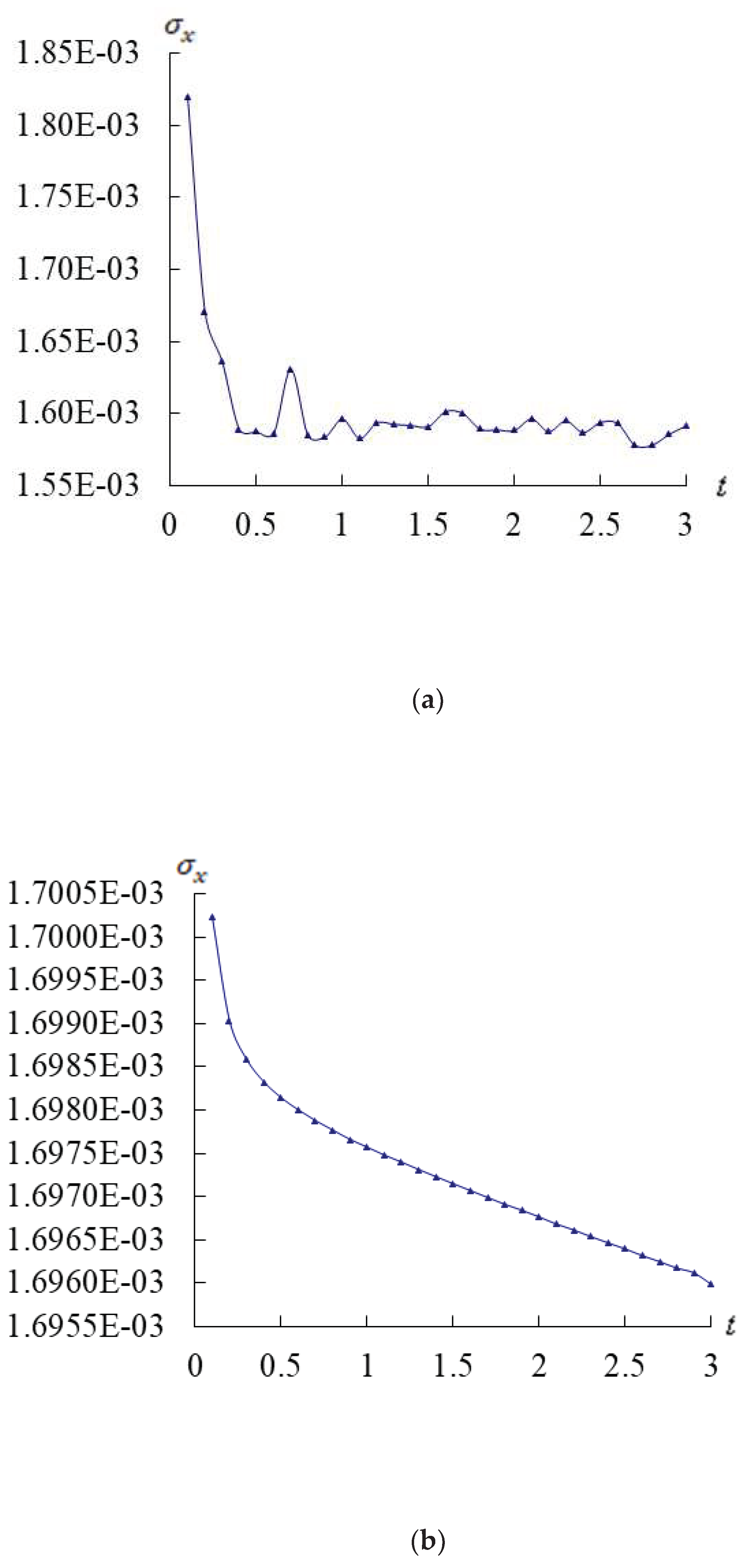
Figure 3 show the time responses of the dominated stress at center position of inner surface z = -0.5 for = 1, =5 and 10, = 0.925925/mm2. The maximum value is 1.8199E-03GPa occurs at t = 0.1s in the periods t =0.1s-3s for = 5. The values have the oscillating and decreasing tendencies in = 0.925925/mm2 for = 5. The values have the decreasing tendency in = 0.925925/mm2 for = 10.
Figure 3.
Advanced (GPa) versus t(s) (a)= 5, (b) .
Figure 3.
Advanced (GPa) versus t(s) (a)= 5, (b) .
3.3. Effects of T and on the advanced responses
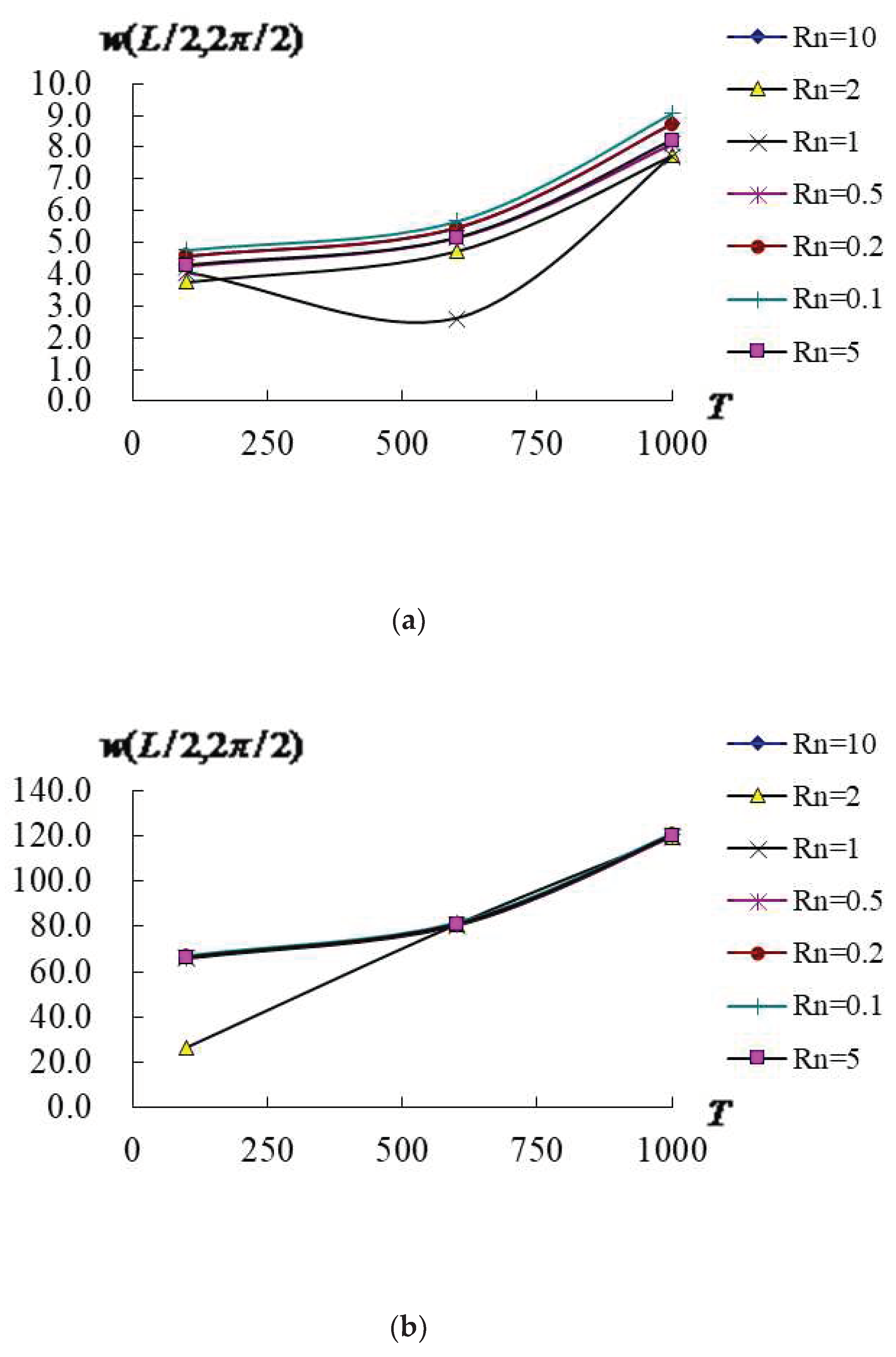
Figure 4 shows the advanced response of vs. T (100K, 600K and 1000K) and at t = 0.1s in FGMs under =100K, = 0.925925/mm2 for = 5 and 10. Figure 4a shows the values of vs. T and for the = 5 case, the maximum value is 9.064334mm in T=1000K for = 0.1. The value have the increasing tendency vs. T, the of the =5 cannot withstand for higher T=1000K. Figure 4b shows the values of vs. T and for the = 10 case, they are almost located in the same curves except for = 2. The maximum value is 120.82637mm in T=1000K. The value have the increasing tendency vs. T, the of the = 10 also cannot withstand for higher T=1000K at t = 0.1s.
Figure 4.
Advanced (mm) versus T(K) with from 0.1 to 10: (a)= 5, (b) = 10.
Figure 4.
Advanced (mm) versus T(K) with from 0.1 to 10: (a)= 5, (b) = 10.
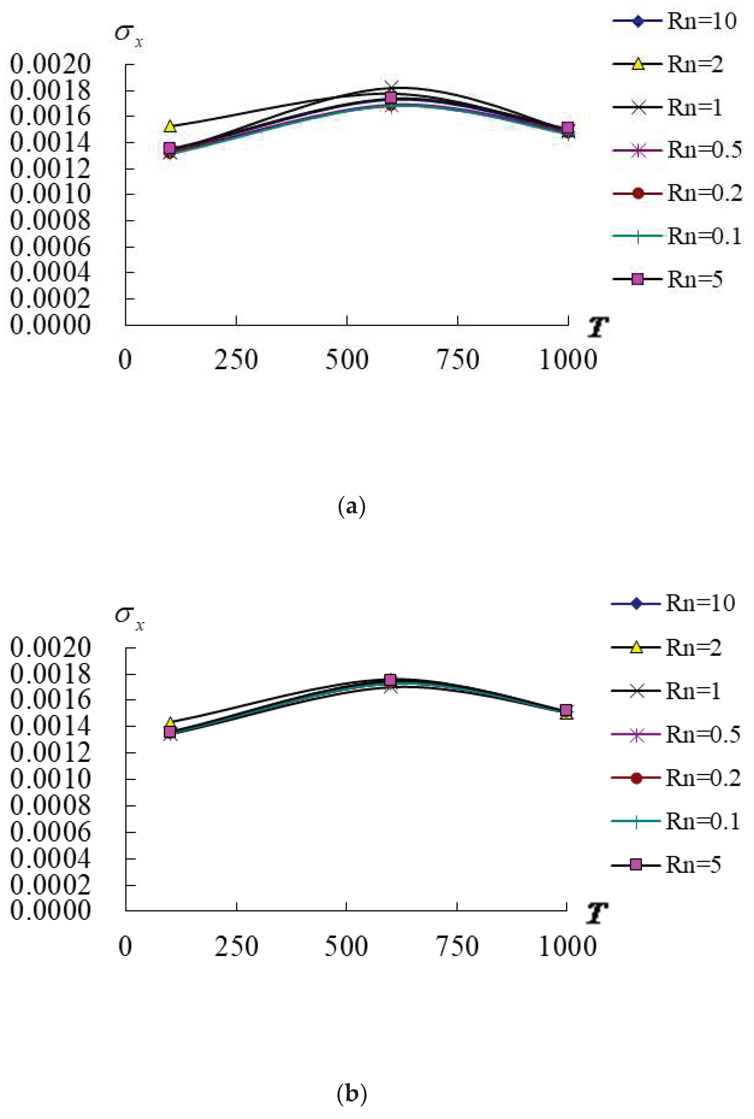
Figure 5 shows the advanced normal stress at = -0.5 vs. T and at t = 0.1s in FGMs under =100K, = 0.925925/mm2 for thick = 5 and 10. Figure 5a shows the values vs. T and for the = 5 case, the value have the increasing tendency from T=100K to T=600K and then decreasing tendency from T=600K to T=1000K. The maximum value is 0.001819GPa in T=600K for = 1. The of the = 5 can withstand for higher T=1000K. Figure 5b shows the values of vs. T and for the = 10 case, they are almost located in the same curves for all value of , the value vs. T have the increasing tendency from T=100K to T=600K and then all decreasing tendency from T=600K to T=1000K. The maximum value is 0.001761GPa in T=600K. The dominated stress of the = 10 also can withstand for higher T=1000K.
Figure 5.
Advanced (GPa) versus T (K): (a) = 5, (b) = 10.
Figure 5.
Advanced (GPa) versus T (K): (a) = 5, (b) = 10.
3.4. Advanced transient responses
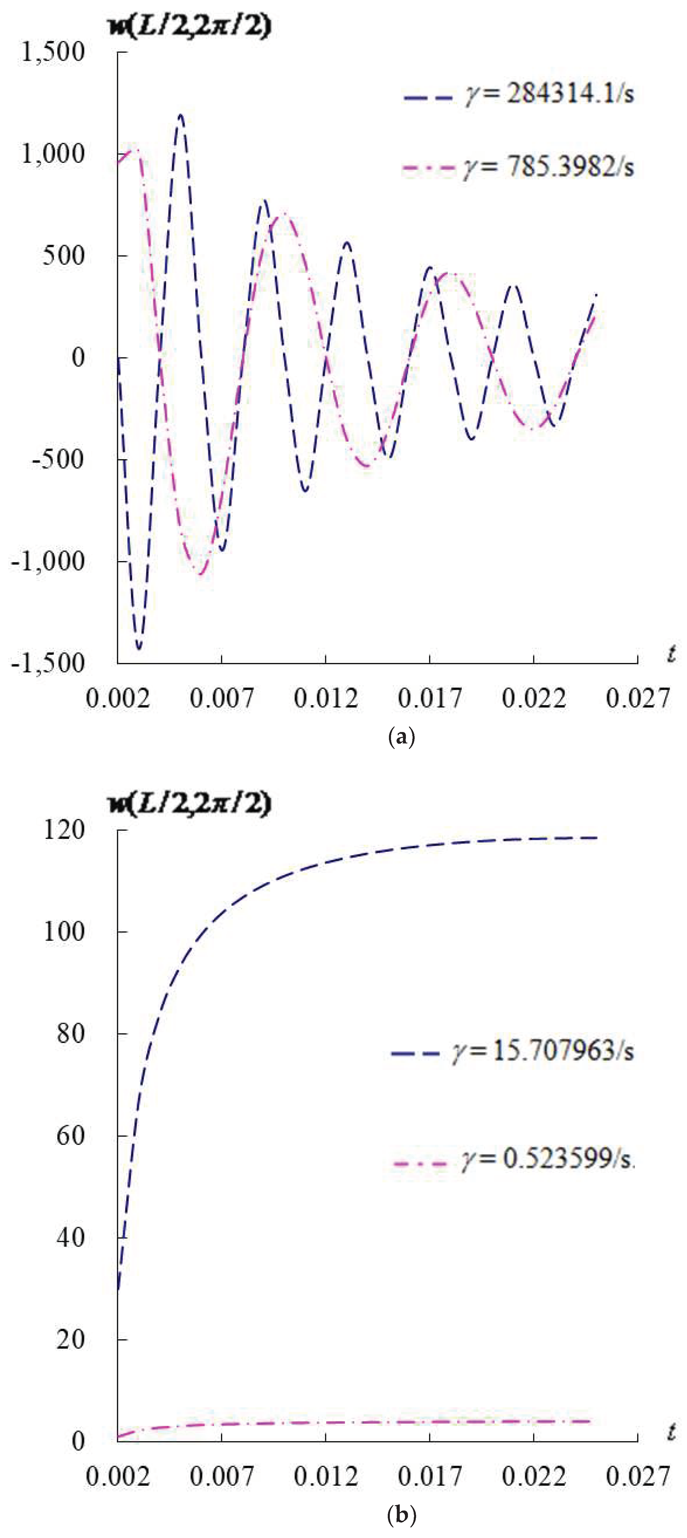
The advanced transient responses of are presented with = 0.925925/mm2 for = 10 and fixed = 0.000592/s as shown in Figure 6. Also used the fixed values of applied heat flux, , = 1.2mm, = 0.6mm, , advanced varied values of = -3.535402, T=600K, =100K for period t = 0.002s-0.025s and time step 0.001s is used. Figure 6a shows the compared transient response of for = 10 with super value = 284314.1/s and high value = 785.3982/s. The transient values of vs. higher are all oscillating and decreasing for = 10. Figure 6b shows the compared transient response of for = 10 with lower values = 15.707963/s and = 0.523599/s. The transient values of vs. lower are all rapid converging for = 10.
Figure 6.
Advanced transient (mm) vs. t(s) for = 10: (a) = 284314.1/s and 785.3982/s, (b) = 15.707963/s and 0.523599/s.
Figure 6.
Advanced transient (mm) vs. t(s) for = 10: (a) = 284314.1/s and 785.3982/s, (b) = 15.707963/s and 0.523599/s.
