Preprint
Review

Applications of Key Autonomous Navigation Technologies for Unmanned Agricultural Tractors: A Review

Altmetrics

Downloads

159

Views

46

Comments

0

A peer-reviewed article of this preprint also exists.

This version is not peer-reviewed

Submitted:

06 February 2024

Posted:

07 February 2024

You are already at the latest version

Alerts
Abstract
Unmanned agricultural tractor (UAT) represents the advanced stage of autonomous navigation and serves as a core technology in agricultural production. It reduces the operator’s workload, and improves operational accuracy and efficiency. This article reviews three aspects of key autonomous navigation technologies for UATs: perception, path planning and tracking, and motion control. The advantages, and shortages of these key technologies on UATs are clarified by analyzing technical principles and the current research status. We conducted summaries and analyses of existing unmanned navigation solutions for different application scenarios in order to identify current bottleneck issues. Based on the analysis of the applicability of key autonomous navigation technologies on UATs, it can be seen that fruitful research progresses have been achieved. The review also summarizes the common problems in current technologies. The application research on sharing and integrating multi-source data for autonomous navigation are relatively weak. There is an urgent need of high-precision, and high-stability sensing equipment. The universality of path planning methods, and the efficiency and precision of path tracking need to be improved. It is necessary to develop high reliability electrical control modules to enhance motion control performance. Overall, advanced sensors, high-performance intelligent algorithms, and reliable electrical control hardware are key factors in promoting the development of UAT technology.
Keywords: 
Subject: Engineering  -   Automotive Engineering

1. Introduction

The loss of the rural labor force has increased, and labor costs are rising rapidly in China[1]. Promoting the development and popularization of unmanned agricultural tractors is crucial for improving land utilization efficiency and ensuring food security. The unmanned agricultural tractor (UAT), enables smart, standardized, and information-based operations [2]. It saves labor and avoids variable work quality caused by differences in operator skills. The autonomous navigation technologies of UATs significantly enhance the quality and efficiency of field operations while reducing the driving difficulty and the operator’s workload [3]. Therefore, it is imperative to study the autonomous navigation technologies of UATs.
Recent years have witnessed rapid developments in UAT. Research on satellite-based Global Positioning System (GPS) and BeiDou Navigation Satellite System (BDS)for the unmanned tractor navigation has been conducted, and practical applications have been implemented. These systems enable intelligent and precise operations, including plowing, land preparation, seeding, and harvesting. However, considerable room for improvement exists in the autonomous navigation technologies of UATs, especially in enhancing efficiency and reliability [4]. Agricultural environments are significantly more complex and diverse than the structured environment of autonomous cars, resulting in great difficulty in path planning and motion control [5]. The key technologies involved in autonomous navigation of UATs include sensing information perception, path planning, and motion control [6], as shown in Figure 1. Only through the comprehensive application of these technologies can autonomous navigation operations of UATs be achieved [7]. Extensive research by scholars worldwide has led to significant achievements in the autonomous navigation technologies of UATs. Understanding the characteristics of autonomous navigation technologies, identifying current bottlenecks, and studying the future development direction are important for the advancement of UATs [8].
Based on the above considerations, this paper presents a comprehensive review of the research progress in the autonomous navigation technologies of UATs. This review focuses on UATs’ technical issues of perception, path planning and tracking, and motion control. It summarizes the advantages and limitations of existing technologies, analyzes the integration of autonomous navigation technologies in UATs, and provides several opinions on technology development.

2. Perceptive techniques of UATs

2.1. Positioning technology

Positioning technology is critical for achieving autonomy and intelligence in UAT. Real-time positioning is a prerequisite for UAT to achieve path planning, path tracking, and motion control [9]. Satellite positioning enables the identification of farmland locations, work areas, and progress [10]. Positioning technologies include satellite positioning systems, laser radar systems, and onboard cameras. These technologies are used in conjunction with UATs to achieve precise and efficient operations [11].
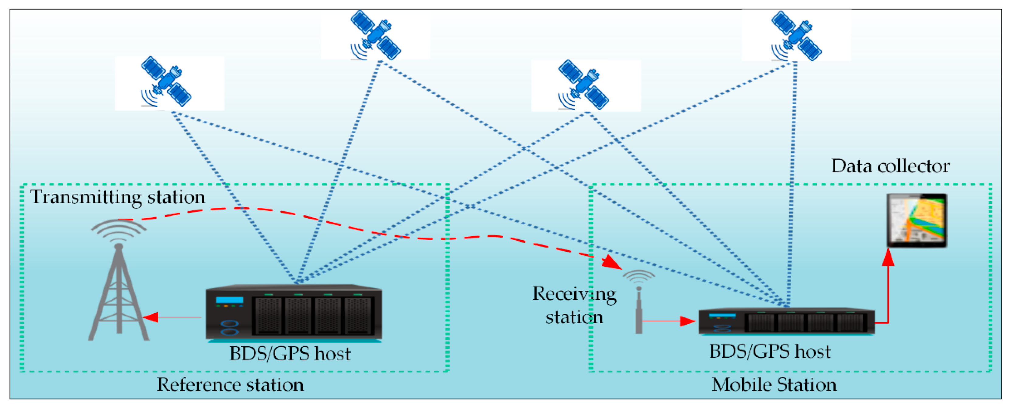
The BDS and GPS are the two most widely used global navigation satellite systems (GNSSs) in agricultural engineering. Positioning data at the decimeter or centimeter level are required to achieve precise navigation of UATs. This is commonly achieved using differential GNSS technology, which enhances the accuracy by transmitting corrected pseudo-range correction values or phase information measured at known reference stations to the mobile station. The diagram of differential positioning is shown in Figure 2. The principles of BDS and GPS are similar, involving the measurement and comparison of signals received by two or more receivers to eliminate signal errors [12].
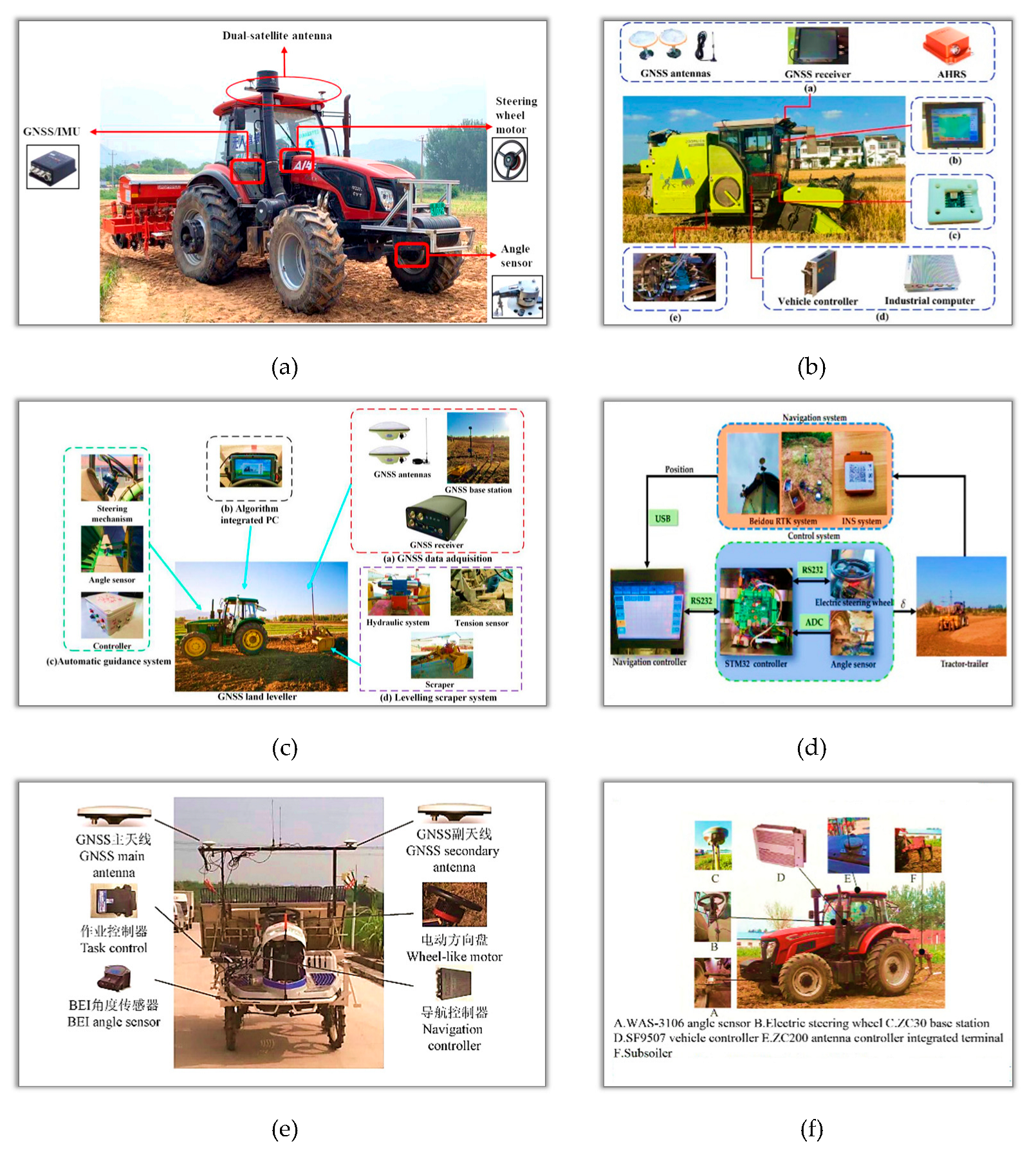
For example, Jing et al. [13] designed an autonomous navigation control board consisting of a high-precision GNSS decoding module and an inertial measurement module, as shown in Figure 3a. This system corrects data from the inertial navigation system (INS) and the high-precision positioning module. It is used to control parameters, such as the direction, speed, and heading angle of the tractors. Yang et al. [14] used the GNSS RTK receiver (Qianxun Positioning Network Co., Ltd., Shanghai, China) to record GNSS data continuously. Its positioning accuracy is ±2.5 cm. GNSS terminals, industrial computers, and mobile devices are used for data reception. The experimental equipment is shown in Figure 3b.
Due to the time delay and overload risk of differential positioning methods, Wang et al. [15] proposed edge computing to reduce the load on the data center, and obtained satisfactory results. Wang and Noguchi [16] evaluated the centimeter-level enhancement service (CLAS) for controlling UAT using the Quasi-Zenith Satellite System (QZSS). QZSS transmits enhanced information through L6 signals to improve positioning accuracy in GNSS.
The deep integration of the BDS system with agricultural systems can provide precise and efficient support for agricultural modernization, promoting the development and enhancement of agricultural production in China. Its application has been scaled in Xinjiang, Heilongjiang, and other regions [17]. For example, the DF2204 tractor (Figure 4a), an autonomous navigation tractor with continuously variable transmission (CVT) and GNSS, was developed for unmanned operations [18]. An attitude heading reference system (AHRS) (MTI-30, Xsens) sensor and a RTK-GPS positioning device were installed in a combine harvester (Figure 4b) for obtaining heading and position information [19]. Two sets of GNSS mobile receivers were developed for obtaining position information, and ensuring the balance of the John Deere 5-904 tractor (Figure 4c) [20]. The BDS and MTI-300 INS were installed in the tractor and trailer to obtain navigation information (Figure 4d), respectively [21]. Figure 4e shows the DF2004-5A navigation driving system based on BDS in a transplanter [22]. Figure 4f shows the GNSS AF300 navigation driving system based on BDS in an AF300 tractor [23].
The GNSS receiver can also provide heading information for UAT. Dual and single antennas have been used to measure the heading information [24]. RTK-GPS and a four-antenna GPS system were used to provide heading information for tractor navigation [25]. The dual antennas of the GNSS system are installed horizontally at the top, enabling simultaneous measurements of position and heading information. GNSS can provide absolute position and heading information continuously in all weather conditions. However, the application of GNSS in complex field environments is limited by signal loss caused by extreme weather or blockages.

2.2. Sensing technology

2.2.1. Field environment perception

The autonomous navigation of UAT requires environmental perception to perform tasks. The main objective of machine perception is to ensure that the UAT operates as expected and safely. Typical applications include obstacle detection, recognition of work area boundaries, and crop monitoring. Due to the challenging conditions faced by the sensors during agricultural operations, such as dust, rain, and extreme exposure to sunlight, sensor reliability has been a key challenge in environmental perception [26]. Currently, various sensors are used in UATs for field environment perception, including monocular vision, stereoscopic vision, lasers, radar, and ultrasonic sensors.
(1) Visual perception
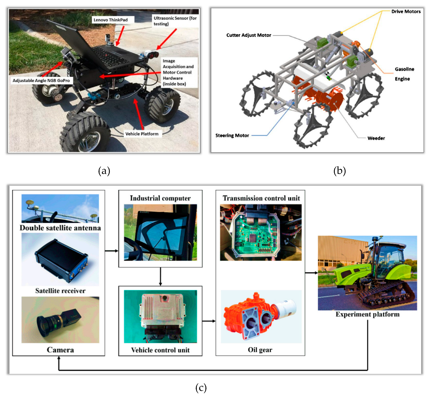
Machine vision localization, perception, and measurement are typically used for the UAT navigation at low speeds. Bakker et al. [27] proposed a row recognition method based on the Hough transform. A color camera was used to capture images of sugar beets in a greenhouse. The color images were converted to grayscale images for creating sufficient contrast between the plant material and the soil background, substantially improving the image processing speed. To obtain real-time autonomous navigation information, Radcliffe et al. [28] integrated a multispectral camera-based machine vision device on a small agricultural vehicle (Figure 5a). The root mean square errors (RMSEs) for automatic navigation were 2.35 cm and 2.13 cm in laboratory and field environments, respectively.
A navigation algorithm of machine vision was developed for a rice field weeding robot [29] (Figure 5b). The results showed that the robot performed well at low weed density, with compensation accuracy of less than 2.5° and an average error from the target path of 4.59 cm. Mahboub and Mohammadi [30] proposed a combined positioning method that integrated BDS and visual navigation, providing accurate and real-time obstacle information in agricultural fields. The position deviation of the tractor was within ±0.1 m, resulting in high accuracy of autonomous navigation. As shown in Figure 5c, Ma et al. [31] developed a visual module for a unmanned crawler tractor to obtain rice crop images in real time. The ExG(2G-R-B) algorithm, and the Otsu and mask method were used for segmenting the binary images.
Machine vision technology utilizes cameras as position measurement sensors. Image processing techniques are utilized to identify crop rows, determine a navigation reference line, and measure the relative position and heading information. The key advantages of machine vision technology are high speed, a large amount of information, and versatile functionality. However, the commonly used Hough transform algorithm has disadvantages, such as the difficulty in determining peak values, multiple repetitions of line segments, and high time and space complexity.
(2) Laser-based navigation
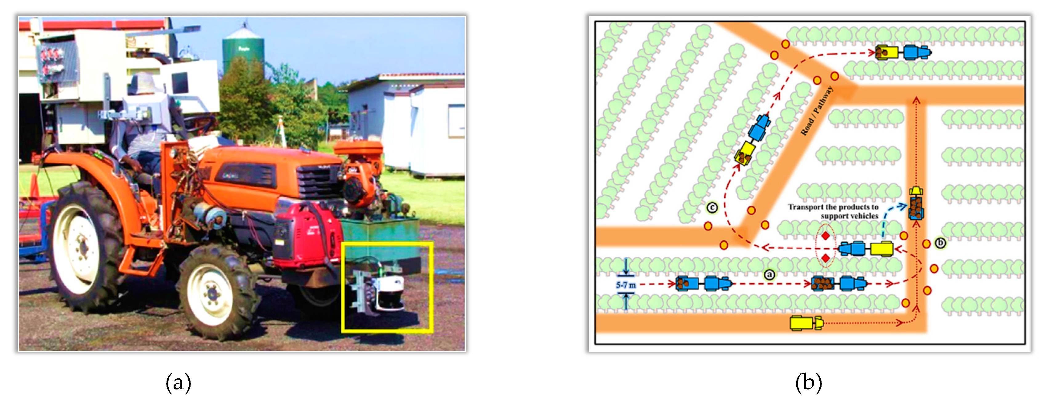
Thanpattranon et al. [32] designed a control method for a tractor-trailer with single-sensor navigation system (Figure 6a) used in orchards. A control scheme (Figure 6a) for stopping the tractor-trailer using a laser range finder was designed for various tasks, as shown in Figure 6b. The results demonstrated that the navigation of tractor in orchards had high accuracy, and the trailer position was adjusted by a sliding hitch bar, enabling wide turns in the paths between the trees. Laser navigation method has many strengths, such as high frequency, high accuracy, and large range. However, it has high costs. This technology is particularly suitable for agricultural robots.
(3) Inertial measurement unit
An inertial measurement unit (IMU) is a measurement instrument based on the principles of inertial navigation, usually consisting of three accelerometers and three gyroscopes. The integration of the angular velocity and acceleration data enables the estimation of the object's velocity, displacement, and attitude information, achieving navigation and positioning [33]. Gyroscopes and accelerometers are the most common components of IMUs. In UATs, gyroscopes are used for autonomous navigation, operation control, and attitude measurement to improve operational efficiency and precision [34]. An accelerometer consists of one or more acceleration sensors, and is widely used in inertial measurement systems of UATs. It has good bias stability and is resistant to vibrations, shocks, and temperature changes.
(4) Multi-sensor data fusion and perception
An INS is a closed-loop navigation system that does not have real-time external information to correct errors during motion. Thus, a single inertial navigation system can only be used for short-term navigation. Long-term navigation systems of UATs need satellite navigation to correct errors periodically.
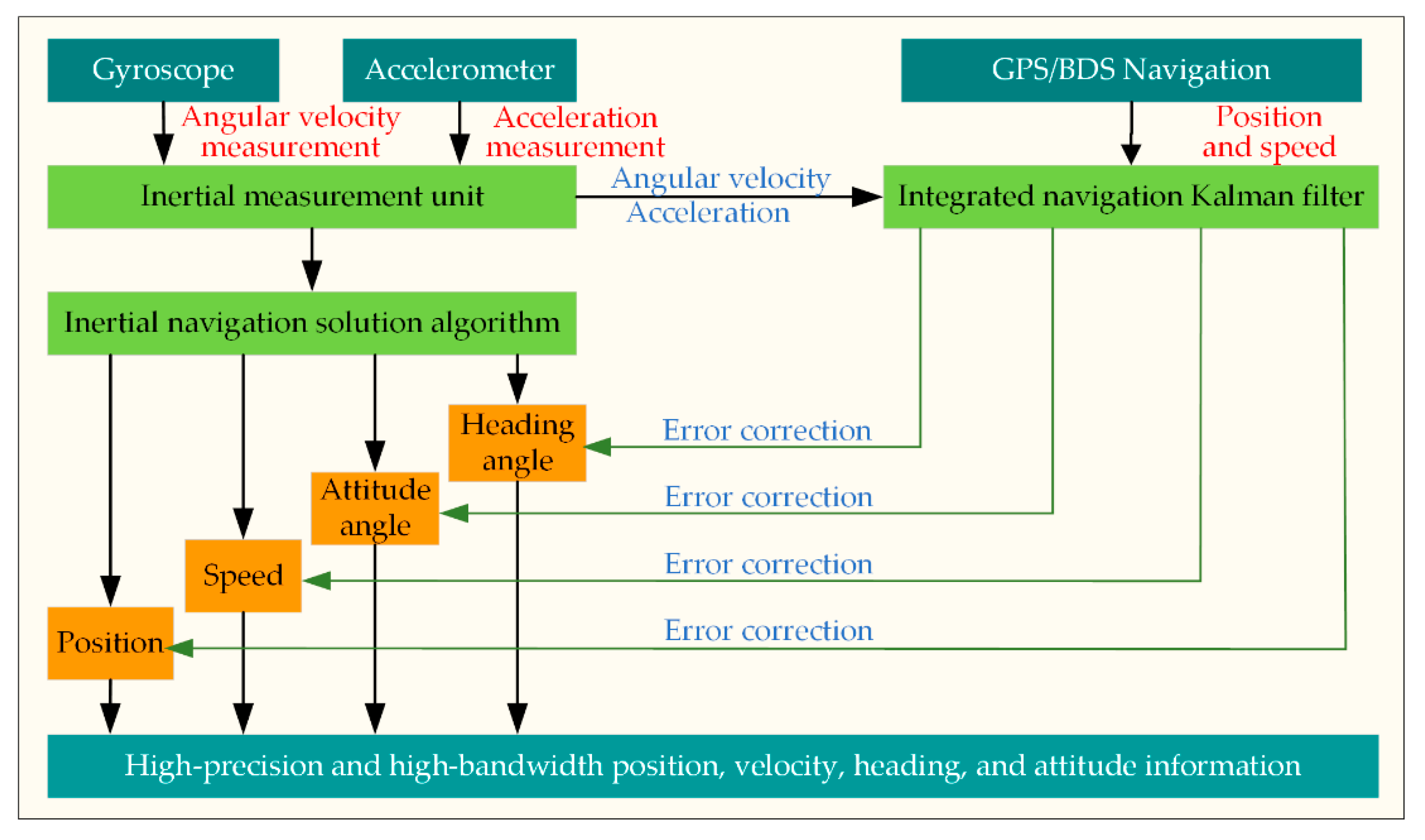
Currently, multi-sensor data fusion is the most widely used approach for UAT navigation. Figure 7 illustrates the combination of inertial and satellite navigation systems. Wang [35] proposed a navigation method consisting of satellite/inertial navigation systems. Experiments were conducted on denoising the data from the satellite/inertial navigation systems, resulting in a navigation accuracy improvement of 2 m. Xia et al. [36] combined information from an IMU and a GNSS. They used a robust regression approach to align the GNSS heading with the vehicle’s longitudinal motion. They also proposed a slip angle estimation method based on the dynamic model. The results showed improved estimation accuracy of the slip angle.
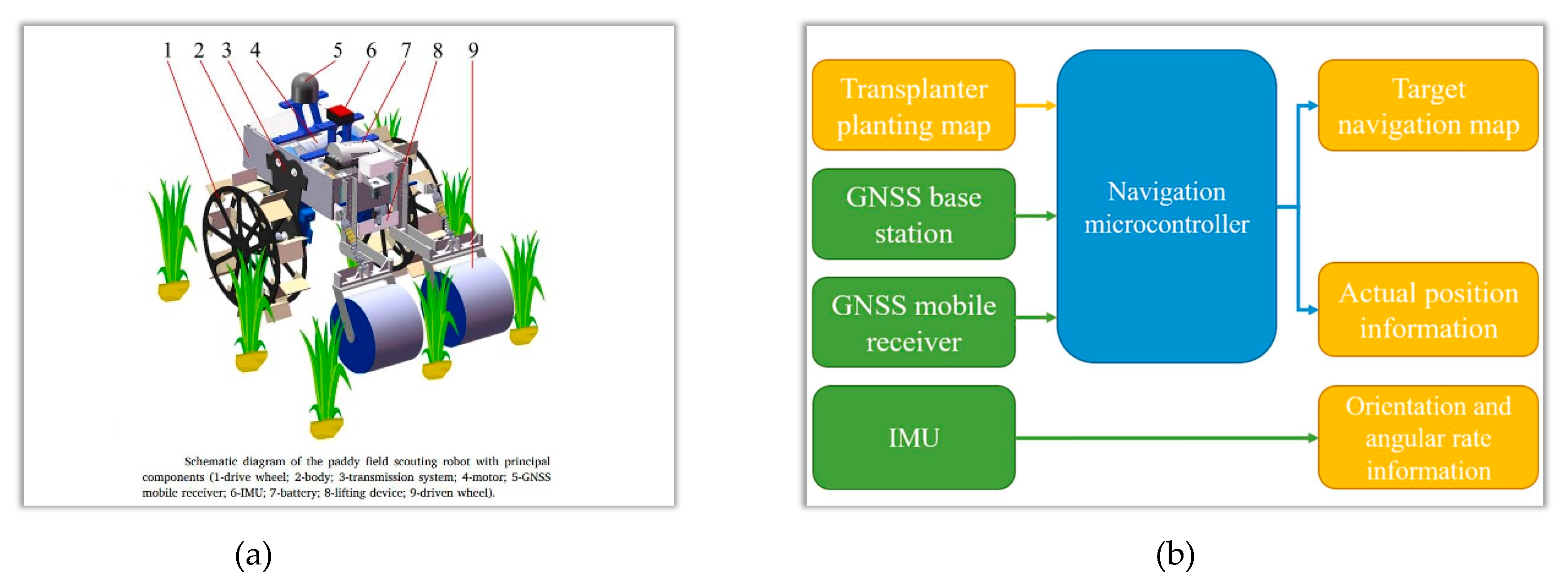
The Kalman filtering algorithm is the main method for sensor data fusion. It can reduce cumulative errors in inertial navigation. As shown in Figure 8, Tian et al. [37] developed a field robot integrated IMU and GNSS navigation system. Kalman filtering was used to correct the errors in the inclination data. Liu et al. [38] proposed an integrated algorithm based on fuzzy reasoning and adaptive Kalman filtering for vehicle navigation and positioning using GPS and inertial navigation. The experimental results showed that the integrated algorithm had better positioning accuracy, precision, and stability than an RTK GPS positioning system.
Favorable results have been obtained from research and applications of laser radar and machine vision in the navigation and obstacle avoidance of UATs. Field environment perception enables the efficient implementation of tasks [39]. However, there are still many challenges, such as data susceptibility to environmental interference, large data volumes, and insufficient real-time performance. Further efforts are needed to enhance the robustness of detection algorithms.

2.2.2. Operation state perception

The perception of operational conditions of UATs primarily focuses on the engine, steering system, transmission system, vehicle body, and wheels. Key parameters include torque, rotational speed, emissions, attitude, vehicle speed, wheel speed, vibration, and strain [40]. The operational condition information includes the traction force of the suspension system, suspension lifting position, power take-off (PTO) torque, PTO speed, hydraulic flow rate, and pressure. Table 1 lists the perception methods for the operational states of UATs.
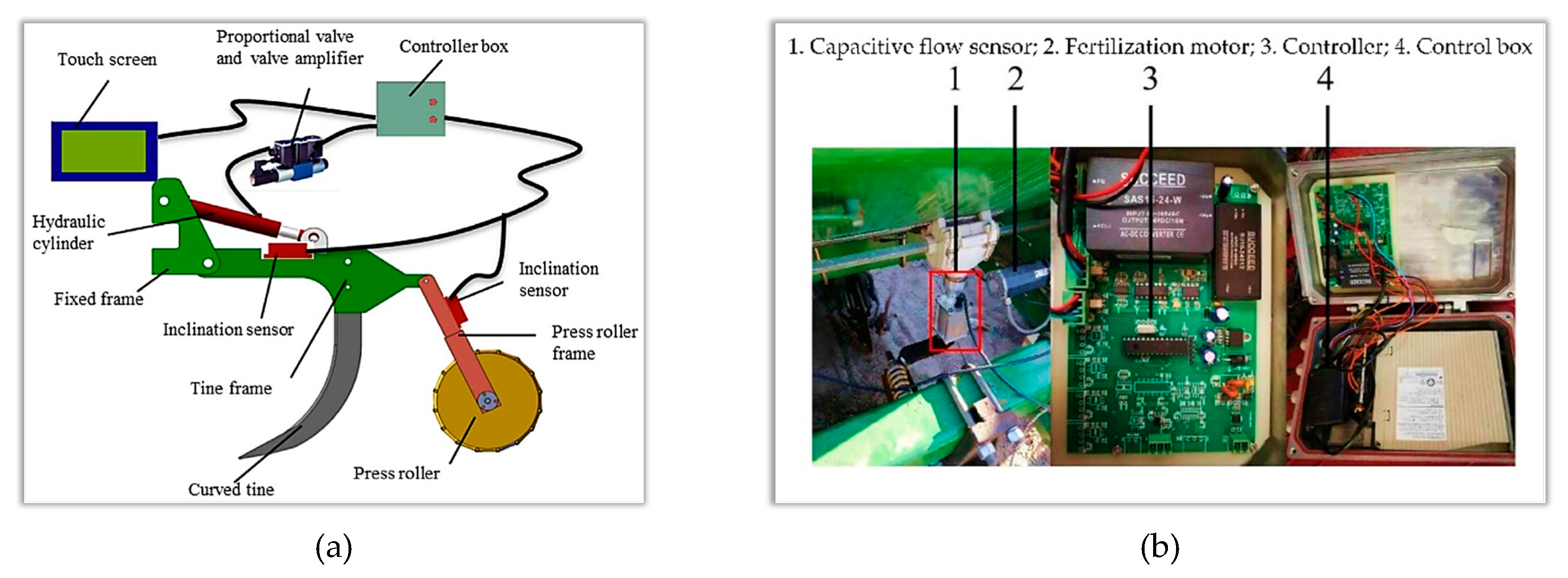
A subsoiler equipped with flexible tines allows for obstacle avoidance while minimizing draft force. However, due to the substantial variation in soil resistance, tilling often results in depths that are considerably lower than the desired target value. To address this issue, researchers developed an electric-hydraulic system for a subsoiler as depicted in Figure 9a [46]. Additionally, they introduced a novel method for detecting the tillage depth to overcome this challenge. The results showed that the control system improved the tillage quality of the subsoiler with flexible tines. Wang et al. [47] devised a precise perception system (Figure 9b) for corn fertilization planters. A capacitance sensor was designed to detect the amount of fertilizer online based on the different dielectric properties of fertilizer and air. The electrically driven seed metering system exhibited an impressive control accuracy of 98% for controlling the grain spacing.

3. Path planning techniques of UATs

3.1. Path planning optimization

3.1.1. Factors of path planning

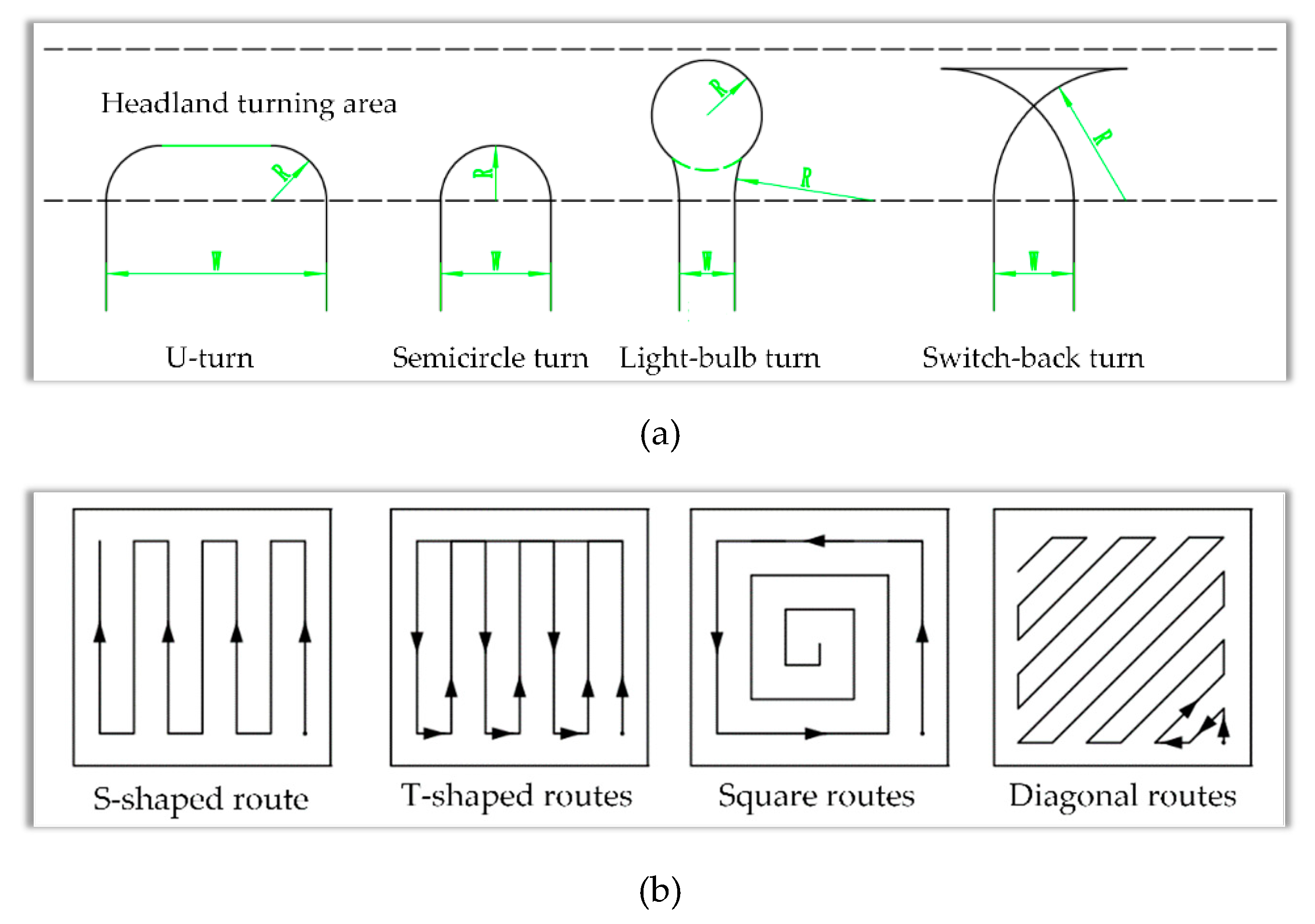
Path planning optimization of UAT requires considering multiple factors, including operation time, turning way, quality, energy consumption, route length, and complexity [48]. The turning way at the end of the field affects the operational efficiency of UATs. Common turning methods include U-turns, semi-circular turns, light-bulb turns, and switch-back turns, as shown in Figure 10a. Each method has advantages for certain applications, and the method should be suitable for specific operation conditions. Different routes are used for different operational requirements. The patterns include S-shaped, T-shaped, square, and diagonal routes, as shown in Figure 10b.

3.1.2. Optimization strategies

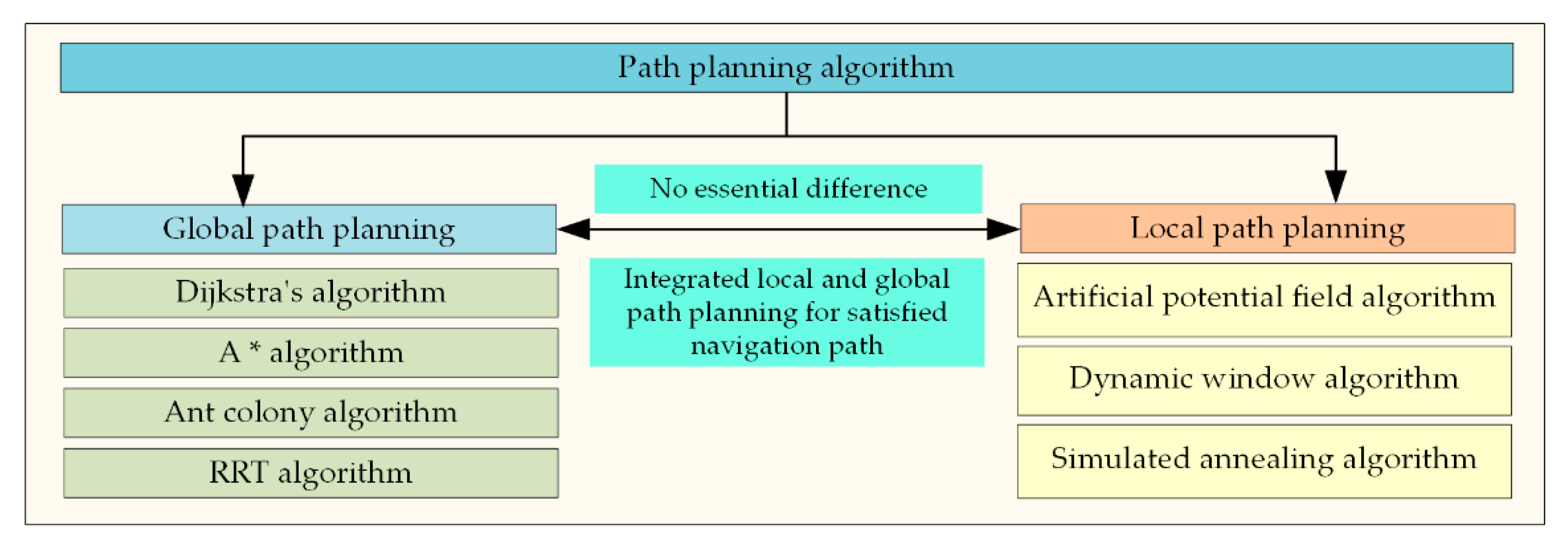
The navigation of UAT requires suitable operation path, turning methods, and speeds. Therefore, field mapping is performed before implementing the automated control of UAT. The field boundaries and obstacles are identified to plan optimal paths for the tractor operations along predetermined routes. The path planning method can be categorized into two types: global (macroscale) and local (microscale) path planning techniques [49], as shown in Figure 11. Each method includes various path-planning algorithms. Based on a pre-existing map, global path planning refers to the process of determining a route from the current location to a designated target position. Local path planning adjusts the motion in real time based on environmental sensing information.

3.2. Global path planning

In UAT driving systems, global path planning utilizes prior information about the terrain and road networks in the field to generate a global path. Real-time localization information is then used for path tracking, enabling the autonomous navigation of the tractor and improving operational efficiency and accuracy. Common global path planning algorithms include Dijkstra's, A*, ant colony, and rapid random tree (RRT) algorithms.
Currently, many researchers proposed improved path planning algorithms for UATs. Alshammrei et al. [50] modeled obstacle-free environments for mobile robots and used the Dijkstra algorithm offline to generate the shortest path, reducing the spatial complexity of the traditional Dijkstra algorithm. The improved algorithm achieved optimal path planning. Li et al. [51] optimized the heuristic function of the A* algorithm using the ant colony algorithm (ACA), resulting in an improved A* algorithm. Experimental results showed a significant reduction in the computation time with the improved A* algorithm.
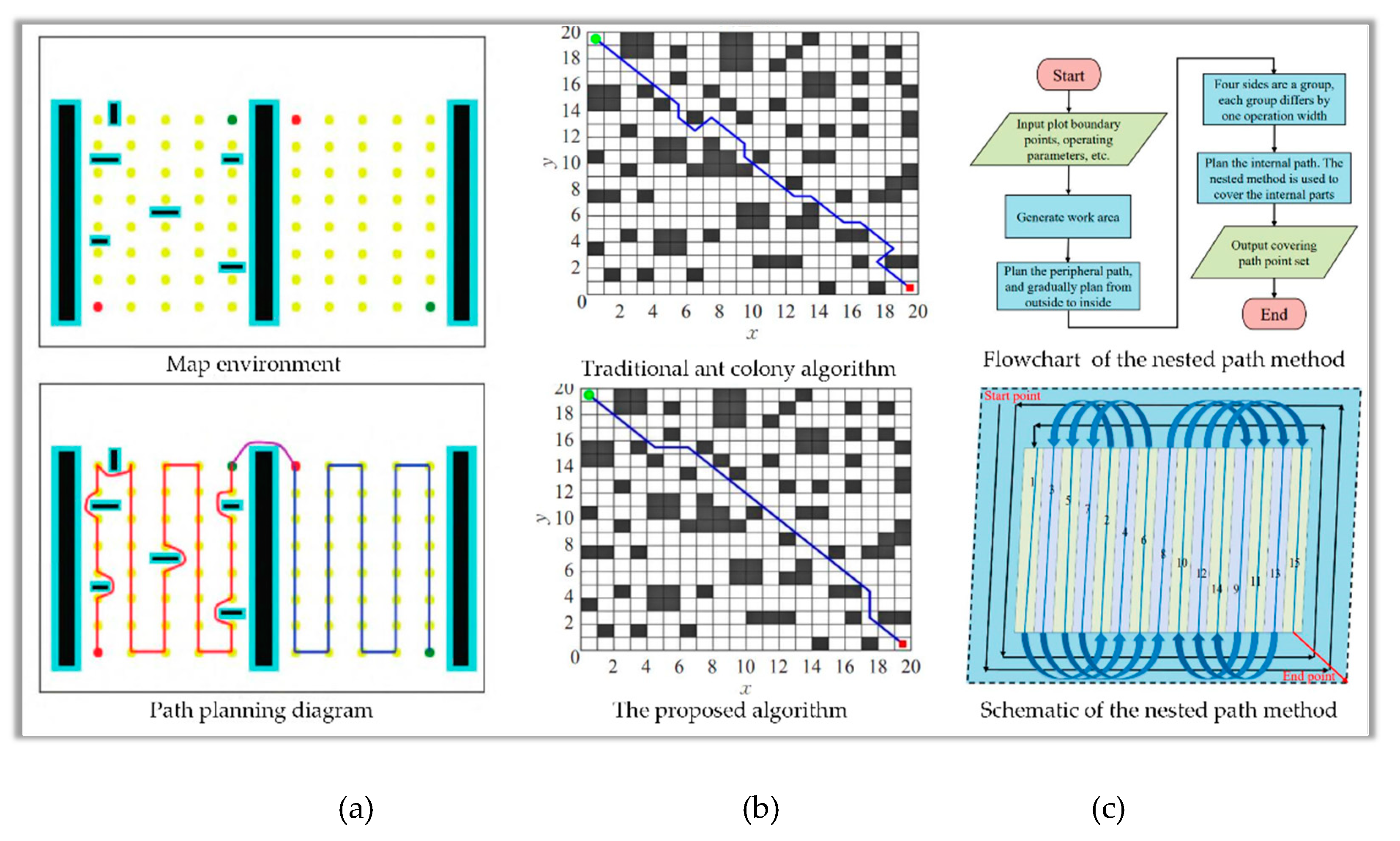
A method based on real-time guided random tree expansion using sampled states was proposed for a UAT to avoid blind searching in the traditional RRT algorithm [52]. The results (Figure 12a) showed that the improved algorithm exhibited better path planning efficiency and adaptability than the traditional RRT algorithm in a kiwi orchard. The task allocation of multiple machines were simulated using MATLAB and an improved ACA [53]. The experimental findings showcased the significant reduction in path costs achieved by the enhanced ACA. He and Fan [54] applied a local block optimization strategy to optimize the subregions separately, significantly improving the convergence speed and enhancing the optimization capability (Figure 12b). Wang et al. [55] developed an improved Dijkstra algorithm based on priority queues to prevent the omission of working areas and speed up the path planning. To enhance the algorithm's effectiveness, it was integrated with various techniques, including the reciprocating method, nested method, and an integration of internal spiral path and nested approaches (Figure 12c). The nested method was the main component. Its flowchart and paths are shown in Figure 12c.

3.3. Local path planning

Local path planning refers to designing a short-term, localized path that guides the UATs based on real-time information on its current position and the surrounding environment. Local path planning enables UATs make real-time adjustments to prevent collisions or getting stuck. Current local path planning algorithms include artificial potential field algorithms, simulated annealing algorithms, and dynamic window algorithms.
In response to the limitations of artificial potential field algorithms, İlhan [56] proposed an improved cross-operator simulated annealing algorithm called ISA-CO to enhance the convergence speed. Li et al. [57] employed a multi-neighborhood search approach to generate novel solutions, while simultaneously enhancing the temperature decay function. As a result, they achieved improved solution quality and accelerated convergence speed. Khan and Mahmood [58] combined two heuristic search algorithms, i.e., simulated annealing and ant colony algorithms, to improve the global search performance and time efficiency, demonstrating good practicality and robustness. Yin et al. [59] proposed a dynamic path planning method that integrated improved A* and dynamic window approach (DWA) algorithms. This achieved the robot's path-planning in highly intricate and challenging by avoiding obstacles, calculating optimal paths in real-time, and maintaining high real-time performance and robustness.
A combination of global and local path-planning techniques is often used for autonomous navigation of UATs in complex environments. Global path planning primarily focuses on route planning between the start and destination points, where motion speed is not a primary concern. On the other hand, local path planning emphasizes speed and direction to cope with complex and dynamic environmental changes. Global and local path planning work in conjunction to derive optimal paths.

4. Path-tracking techniques of UATs

4.1. Motion model for path-tracking

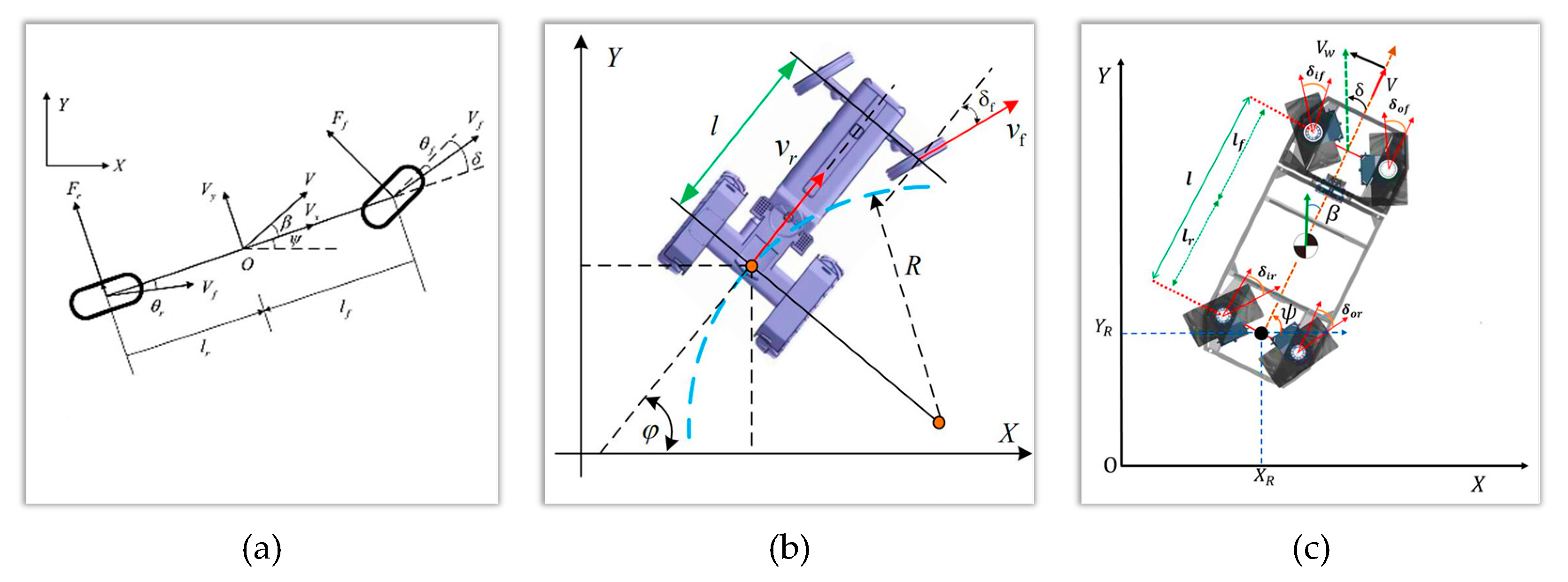
Control algorithms are used for path tracking to ensure that UAT travels on the desired path at the required speed. In the navigation control system, the motion model regards the tractor as a rigid body, considering the tractor’s physical properties and the forces acting on it. The linearized bicycle motion model is a simple and widely applicable approach. As shown in Figure 13a, the UAT is abstracted as a two-wheeled vehicle in this motion model, using the X and Y coordinates of the rear wheel center of the tractor in the Cartesian coordinate system. The front wheel steering angle of the vehicle is controlled based on the position, attitude, and velocity of the tractor [60].
Fan et al. [61] developed an improved quantum genetic algorithm and weighting matrix optimization for weight selection of a UAT. The Ackermann steering principle was utilized to establish the kinematic model of the tractor. Subsequently, the model was discretized and linearized, as shown in Figure 13b. The vehicle model in Figure 13c was a four-wheeled steered robot used in agricultural applications. The robot was assumed to move without skidding in a two-dimensional planar environment [62]. The vehicle state and the input driving coordinates were obtained from steering encoders, and the information was translated into vehicle navigational commands.
The planned navigation path represents the intended trajectory for UATs. It is crucial to research various aspects to track and control the path, including UAT motion models, navigation decision control, as well as steering and braking control. Furthermore, future efforts may focus on developing scientifically accurate motion models to enhance the efficiency and precision of path tracking.

4.2. Path tracking algorithms

4.2.1. Pure pursuit method

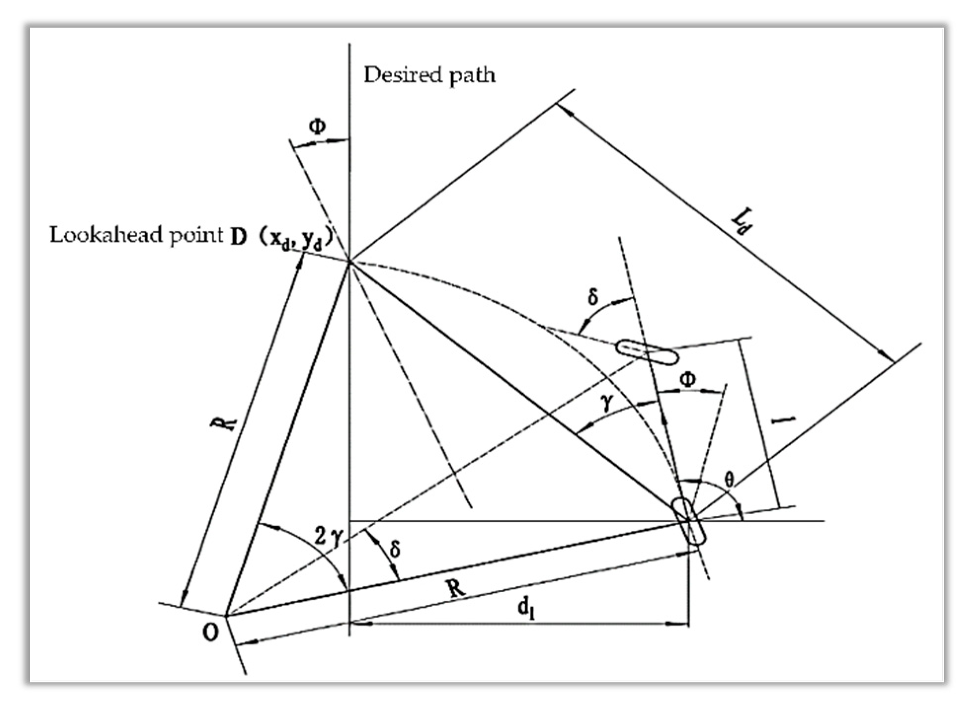
By employing the pure pursuit method, UAT can assess deviations in both position and orientation from the desired trajectory. This method effectively calculates distance and orientation errors to facilitate precise navigation. Control algorithms are then used to minimize the errors and achieve accurate path tracking. The pure pursuit method is computationally simpler to implement than other path-tracking approaches. It also provides high path-tracking accuracy in most scenarios. This method utilizes a lookahead point, as shown in Figure 14 [63]. The rear axle center of the UAT is the reference point, and a target point on the desired path is selected at an appropriate distance (lookahead distance). The front wheel steering angle is then calculated based on the real-time lateral and heading deviations. The UAT follows an arc toward the lookahead point to reach the desired target point at a certain velocity [64,65].
Yang et al. [66] proposed a path-tracking algorithm of a UAT based on an optimal target location. Its control scheme is shown in Figure 15. This algorithm optimizes the lookahead distance adaptively by simulating the driver's lookahead behavior. It determines the lookahead region, establishes an evaluation model, and searches for the optimal target position based on the predicted model of the tractor's position. The proposed method exhibited a tracking error that was 20% lower in comparison to the pure pursuit algorithm.

4.2.2. Pole-zero configuration

Pole-zero configuration refers to selecting the positions of poles and zeros in a signal processing system. It is used to design filters or controllers to meet UAT system performance requirements. An appropriate pole-zero configuration ensures high stability, fast response, and minimum disturbance of a control system [67]. For example, adjusting the positions of the proportional–integral–derivative (PID) controller's poles and zeros can control the system’s overshoot, response time, and steady-state error.

4.2.3. Model predictive control

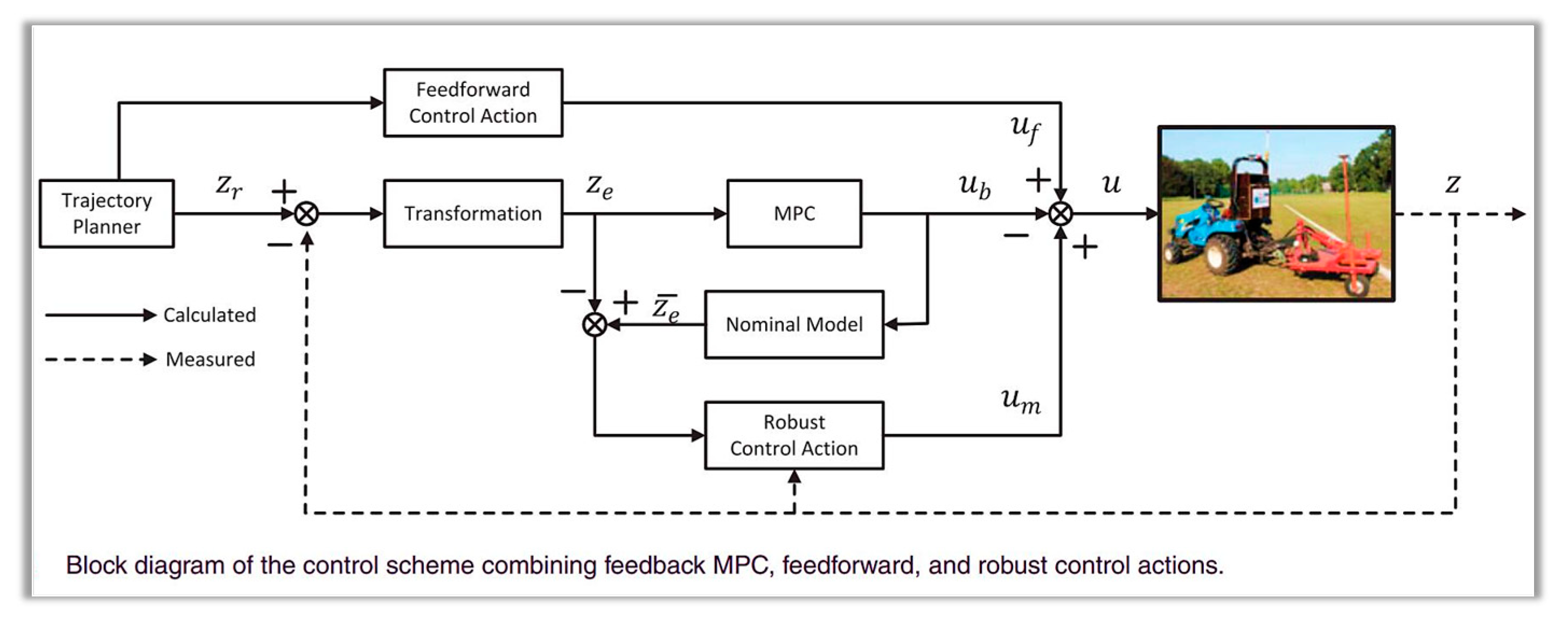
Model predictive control (MPC) utilizes predictive models to select appropriate control actions based on the optimization objectives. It applies the control signal in the first time step, and applies updated control signals at subsequent sampling intervals. Kayacan et al. [68] proposed a robust trajectory-tracking error control method for UATs. They designed a linear model predictive controller based on the tracking error. This controller combines feedforward and robust control actions, significantly reducing tracking errors. The control scheme is depicted in Figure 16. Liu et al. [69] presented a path-tracking MPC method for autonomous navigation vehicles. A comparison experiment was conducted with linear model predictive controllers. The proposed method resulted in fewer horizontal and longitudinal deviations from the track during circular path tracking. He et al. [70] developed a linear model, objective function, and constraint function using MPC for paddy field tractor. They utilized the tractor's pose to establish a path tracking MPC method and proceeded to conduct field experiments. The results indicated that the pose-corrected MPC path tracking method prevented sudden lateral position errors caused by changes in relative position and attitude.

4.2.4. Linear quadratic regulator

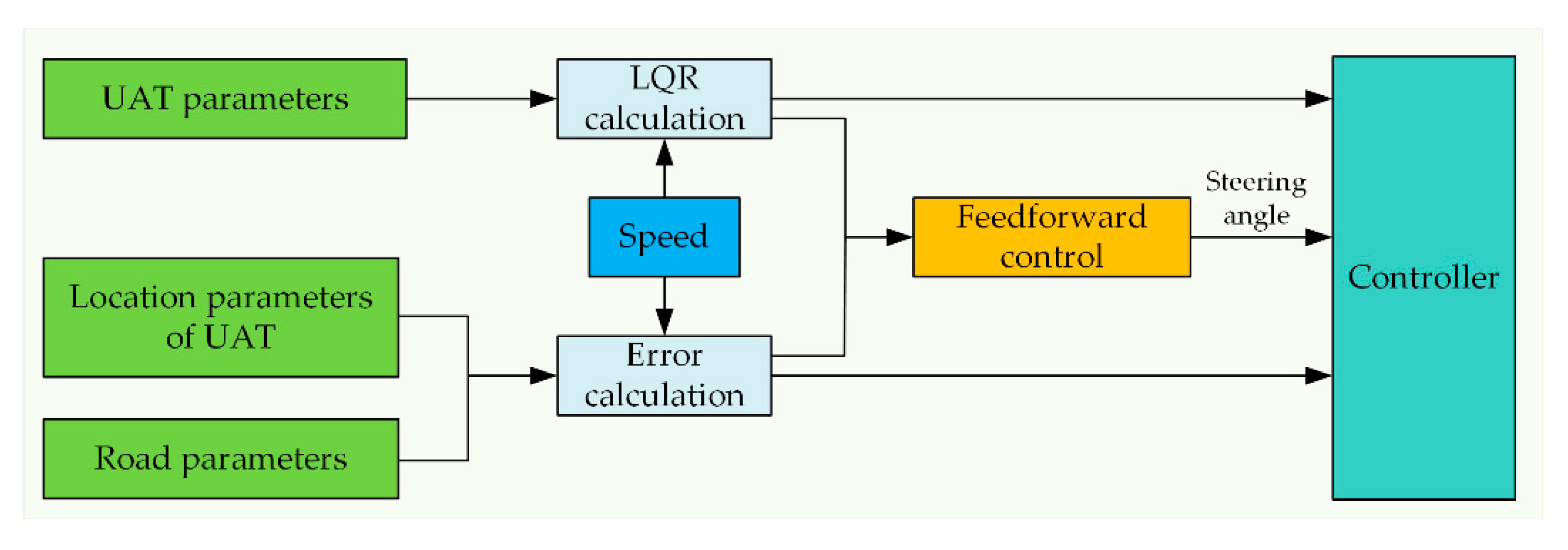
A linear quadratic regulator (LQR) is a control system optimization method. It optimizes the control parameters of linear dynamic systems to achieve improved system performance [71,72]. Bevly et al. [73] designed an LQR path-tracking approach based on a yaw dynamic model. The experimental results demonstrated that this model could control the tractor’s lateral movement within 4 cm at speeds of up to 8 m/s, providing accurate high-speed navigation control of tractor. The block diagram of the principle is shown in Figure 17.

4.2.5. Other novel approaches

In order to improve the adaptability of the full field path tracking algorithm, Cui et al. [74] proposed an improved fuzzy path-tracking control method for a UAT and modified the Stanley model. It dynamically adjusts the gain coefficient. Field tests showed that the maximum path-tracking error for straight and curved trajectories at the rated operating speed was less than 3 cm. Bodur et al. [75] developed an automatic path-tracking system that used two lookahead reference points (2-LARP) to compensate for attenuated oscillations at curvature transitions. They found that the proposed algorithm reduced the peak lateral error to 20% of the error of the 1-LARP controller, significantly reducing lateral tracking deviation.

5. Motion control techniques of UATs

5.1. Control methods for automatic navigation

The automatic navigation control of UAT primarily focuses on the lateral position control. It ensures that the tractor remains on the planned operational path. It also can guarantee the lateral position deviation from the path remains within a certain range. Therefore, motion control is required for the autonomous navigation of UAT [76].

5.1.1. PID control

The most commonly used control method for unmanned vehicles is PID control [77,78]. He et al. [79] researched unmanned tracked peanut harvesters and improved the PID path-tracking algorithm. They proposed a dual-PID path-tracking control algorithm based on preview tracking and a virtual rotation angle. The real-time positioning data of the harvester are shown in Figure 18. This method exhibits smooth control and small steady-state errors.

5.1.2. Neural networks

Backpropagation (BP) neural networks possess strong adaptive capability to deal with uncertainties and low robustness of unmanned driving control. They have been used to optimize the parameters of navigation algorithms and improve the control accuracy and applicability [80]. Vargas-Meléndez et al. [81] proposed an integrated method of neural networks and Kalman filtering to estimate the vehicle's tilt angle. This method achieved better results than an estimator that used the suspension deflection to obtain pseudo-tilt angles.

5.1.3. Fuzzy control

Unlike traditional control methods, fuzzy control does not require precise mathematical models and geometric relationships. Instead, it converts fuzzy linguistic descriptions into mathematical forms to describe imprecision and ambiguity. Meng et al. [82] proposed an improved particle swarm optimization-based adaptive fuzzy control method. This method quickly eliminates lateral errors in navigation operations of UAT and has a small overshoot and fast response. Xue et al. [83] designed a path-tracking controller for agricultural robots using fuzzy control and machine vision methods with a variable field of view. This controller enabled the autonomous navigation of robots in cornfields, and field experiments demonstrated its effectiveness.

5.1.4. Sliding mode control

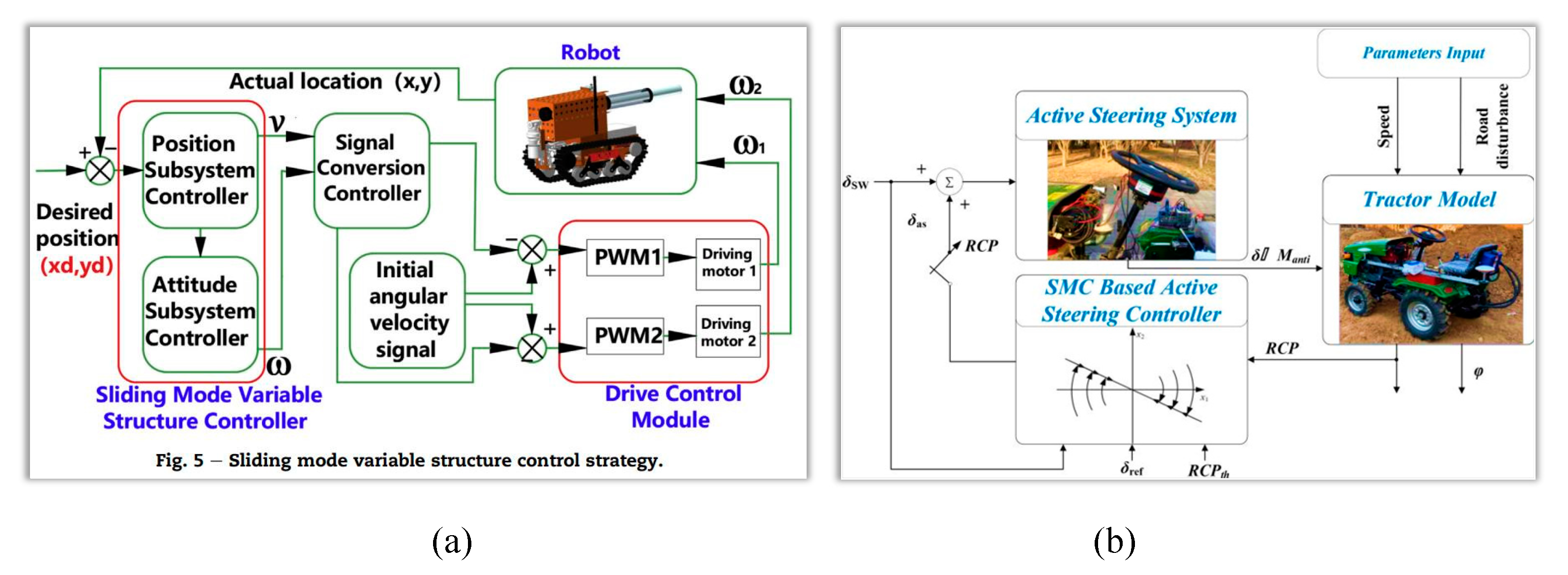
Sliding mode control (SMC) is utilized to address system uncertainties and disturbances by employing robust and adaptive controllers. It has high robustness, fast response, and high control accuracy [84]. Li et al. [85] proposed a sliding mode variable structure method to design a path following control algorithm for a UAT (Figure 18a). The implemented control system allowed the tractor to efficiently carry out plant protection operations in maize rows during the late season. Jia et al. [86] proposed a radial basis function (RBF) network for the adaptive SMC of the tractor’s steering angle. The method exhibited high fault detection capability, reliability, and accuracy. Additionally, the method reduced the failure rate of front-wheel steering angle measurement devices. He et al. [87] utilized the SMC method based on the exponential terminal sliding mode (TSM) surface to accelerate the system's response speed. They provided evidence that the SMC-active steering (AS) control method exhibited superior performance compared to the PID-AS control technique in terms of minimizing peak roll angles. The control system's structure is shown in Figure 18b.
Figure 18. Diagram of the sliding mode controller for (a) the path of a UAT [85] and (b) the active steering system [87].
Preprints 98339 g018

5.2. Motion control of UATs

5.2.1. Steering control

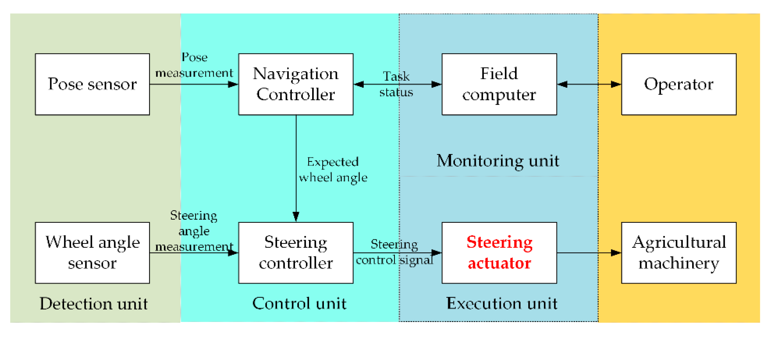
The structure of a typical control system for UAT is shown in Figure 19 [88]. The control of the execution unit is critical for achieving autonomous navigation. The steering actuator controls the steering motion of UAT. It converts the control signals from the steering controller into the steering torque to cause the wheels to turn. Mechanical and hydraulic steering actuators are commonly used. The mechanical type has an electric motor to power the steering axle of UAT. It is easy to install and widely adaptable.
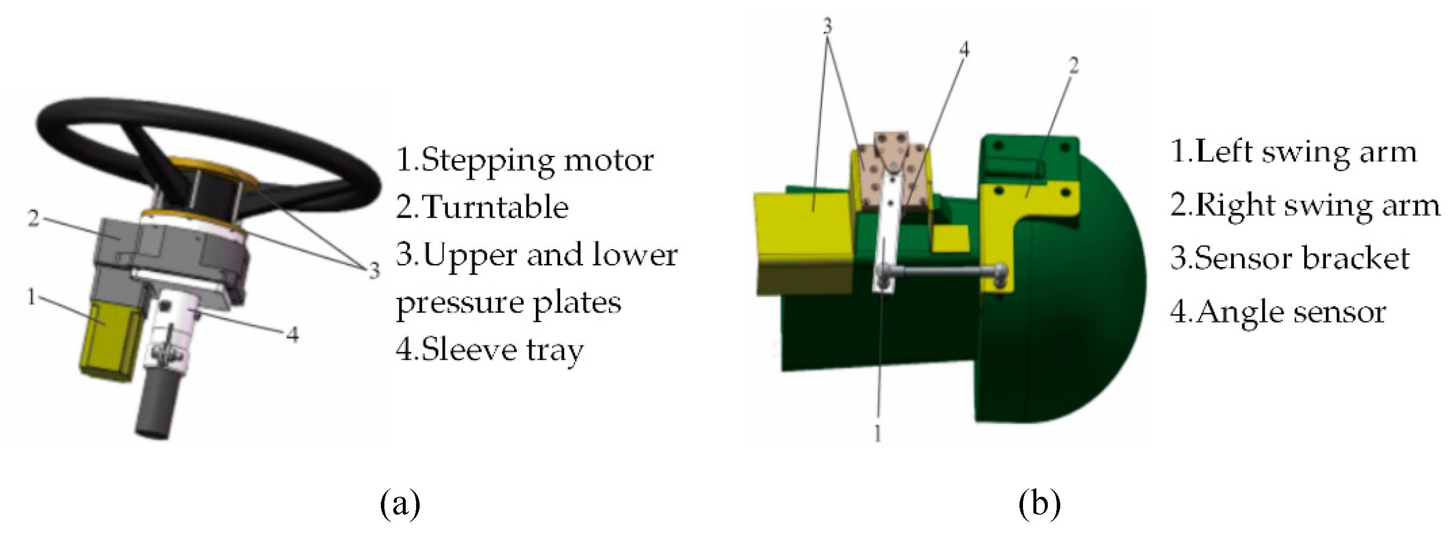
Mechanical and hydraulic steering systems have low accuracy, slow response, and large errors. They are unsuitable for high-precision operations of UATs. Electronic steering control is widely used. Electronic devices precisely control the motor's speed and steering angle. Zhang et al. [89] used a PLC (Programmable Logic Controller) and a stepping motor to control the steering wheel's rotation (Figure 20) and achieve automatic navigation. Li et al. [90] proposed a PID control method for a four-wheel steering system. They designed a hydraulic multi-wheel steering system to improve the maneuverability and operational efficiency of a sprayer. The Autonomous driving of UAT requires the control of basic functions like forward motion, stopping and the ability to make quick turns. Therefore, steering control is crucial, and lateral torque control ensures rapid turning of the UAT [91].
As shown in Figure 21a, Yang et al. [92] created an autonomous steering system specifically designed to enhance the maneuverability of UATs during turning maneuvers. Based on the experimental findings, the implementation of the auxiliary wheel turning approach demonstrated considerable improvements in multiple aspects of the automatic tractor's performance. Specifically, it boosted time efficiency by 50%, slashed travel distance by 80%, and reduced spatial requirements by 50% in contrast to traditional turning approaches. Xu et al. [93] proposed a method to estimate a UAT’s steering state and parameters. The mechanical model of the coupled electro-hydraulic steering method is shown in Figure 21b. The controller analyzes the required steering torque and calculates the appropriate current to activate the steering motor, thereby facilitating the desired rotation of the motor.

5.2.2. Brake control

The brake control module is a key component of the automatic control system. It controls the brakes to decelerate the vehicle. The objectives of brake control of UAT are to adjust the braking force, stop the vehicle, reduce the speed, and ensure that the moving object operates in a safe and stable manner. The design of the brake control module must consider multiple factors, such as control algorithms, brake types, dynamic adjustment, real-time control, and safety. It requires targeted design and implementation to achieve efficient, precise, and safe brake control.

5.2.3. Speed control

Precise speed and turn control improves operational efficiency, enhances work quality, and ensures operational safety of UAT. Speed control autonomously adjusts the vehicle's velocity based on the required tasks or environmental changes. Automated speed control can adjust the speed with high precision based on the required tasks, work site, and terrain. Li et al. [94] designed an experimental platform based on a crawler tractor and an RTK-GPS control system. This system enables the UAT to follow predetermined routes and achieve low tracking errors.
Common control techniques for turn control include steering wheel angle, differential, and dual-layer PID control methods. The turn control for autonomous driving systems requires multiple data sources, such as GPS position information, to improve control accuracy and vehicle safety. Zhou et al. [95] proposed a hybrid electro-hydraulic steering system with an improved method based on a competitive multi-objective particle swarm optimization algorithm. This system facilitated steering with an improved steering feel and reduced steering wheel backlash. He et al. [96] introduced a dynamic turning path planning technique targeted at UATs. The primary objective of this approach is to minimize both the path length and time required for turns. The aim was to minimize lateral and heading deviations. The proposed algorithm reduced lateral deviation by 78.75% and outperformed conventional turning methods.

5.3. Controller area network bus technology for UATs

Advances in controller area network (CAN) bus technology have resulted in increased applications for UATs. Communication between electronic control units using CAN bus has been achieved in some developed countries [97]. The intelligence of smart agricultural machinery depends on the communication level, hardware structure, software architecture, and algorithms. Communication is required to ensure intelligent applications. Rohrer et al. [98] investigated the CAN bus technology for tractor data acquisition. The results showed that Leaf Light v2 and CanKing software could provide raw logging data. CANcaseXL_log hardware combined with the CANalyzer software enabled the conversion of the raw logging data into a file to visualize the data. To examine variations in data acquisition and conversion, Marx et al. [99] utilized diverse data acquisition methods to collect CAN bus data from tractors. The CAN module is shown in Figure 22a. The results showed that using the waveform CAN bus data maintained the accuracy of digital data and reduced the processing time and memory requirements. Liu et al. [100] developed a CAN communication network system following the ISO 11783 protocol specifically designed for a bifurcated power electric tractor. The topology diagram of the CAN communication network is shown in Figure 22b. The results showed that the bus load rate of the proposed CAN bus network system was 12%, meeting the communication requirements. The research status of the use of CAN bus technology for the autonomous navigation of UAT reveals that this technology has been commercialized internationally, whereas China is in the research and experimental stage.

6. Conclusions and outlook

6.1. Conclusions

Extensive and comprehensive research has resulted in advances in the autonomous navigation of UAT. The critical, intelligent technologies include GNSS, inertial navigation systems, fusion of positioning data and sensor information, integration of global and local path planning, and precise motion control. Based on a thorough summary and analysis of current research, the following conclusions can be drawn:
(1) GPS and BDS are widely used GNSS technologies for differential positioning. Nevertheless, the utilization of GNSS technology for the autonomous navigation of UAT remains relatively limited due to extreme weather conditions or signal disruptions. Various sensors used in this field have both merits and drawbacks. Sensor fusion methods are commonly employed to increase positioning accuracy and reliability. Widely adopted information fusion approaches include Kalman filtering and particle filtering.
(2) The motion model precision significantly impacts the accuracy of UAT navigation, especially in complex field environments. Path planning and tracking are influenced by field conditions, types of machinery, and turning radius. Achieving effective and practical automatic boundary steering remains a challenging issue in autonomous navigation control, particularly for turns at the field boundaries. Obstacle detection in the field can be accomplished using machine vision methods or laser ranging. Stopping the machinery is the simplest obstacle avoidance measure because a real-time path-planning approach for obstacle avoidance is not yet available.
(3) The control of steering, speed, and brake is crucial for the final implementation of autonomous navigation, and ensures the working precision and motion reliability of UAT. The combination of traditional and intelligent control algorithms, coupled with high-performance steering controllers, is crucial for improving the navigation efficiency and precision of UAT.

6.2. Future outlook

(1) The use of GNSS technology for the autonomous navigation of UAT needs to be strengthened. It is necessary to conduct research on creating practical and efficient autonomous navigation scheduling systems tailored to China's conditions. It is crucial to design appropriate sensor combinations, select reliable and effective sensor fusion strategies, and leverage the advantages of sensors to ensure data redundancy or complementarity. These are important steps to improve navigation robustness and accuracy. Accelerating the usage of the Internet of Things and communication technology for environmental perception is also essential for the autonomous navigation of UAT.
(2) Full-coverage path planning algorithms suitable for irregular fields, multiple obstacles, and multiple constraints need be developed to achieve adaptive path planning for tractors and implements with different turning radii. It is required to develop advanced obstacle avoidance measures suitable for the operating environment of UAT. Real-time obstacle avoidance path planning should be implemented for the dynamic control of tractor and obstacle avoidance. Extensive research may be conducted to develop science-based mathematical models and algorithms for path planning and tracking to enhance efficiency and precision.
(3) A big data cloud platform with 5G high-speed networks need be established for UAT to promote the deep integration of big data and smart machinery. This platform would enable remote operation decisions and motion control. CAN bus technology can facilitate data exchange among electronic units with simple wiring, good real-time performance, and high reliability. This technology is suitable for data communication in complex field environments and ensures smart and accurate navigation of UAT. Extensive research is required to conducted on achieving high-precision and high-reliability motion control units.

Author Contributions

“Conceptualization, J.Q., Z.Z., and K.G.; investigation, J.Q., Z.Z. and Z.Q.; writing—original draft preparation, J.Q., Z.Z. and Z.Q; writing—review and editing, J.Q. and K.G.; visualization, Z.Z., Z.Q. and D.L.; supervision, K.G. and D.L.; project administration, J.Q., and K.G.; funding acquisition, J.Q. All authors have read and agreed to the published version of the manuscript.”

Funding

This research was funded by the Jiangsu Provincial Natural Science Foundation [grant number BK20210823]; the Natural Science Foundation of the Jiangsu Higher Education Institutions [grant number 22KJD510012 and 23KJD510013]; Lvyangjinfeng Talent Project of Yangzhou, grant number YZLYJFJH2021YXBS055.

Data Availability Statement

Data are all contained within the paper.

Acknowledgments

The authors are grateful for the support by Jiangsu Engineering Center for Modern Agricultural Machinery and Agronomy. The authors also express their sincere appreciation to the editor and referees for their valuable time and efforts on our paper.

Conflicts of Interest

The authors declare no conflict of interest.

References

  1. Lu, W.; Li, J.; Qin, H.; Shu, L.; and Song, A. On Dual-Mode Driving Control Method for a Novel Unmanned Tractor With High Safety and Reliability. IEEE-CAA J. Autom. Sin. 2023, 10, 254–271. [Google Scholar] [CrossRef]
  2. Han, X.; Lai, Y.; and Wu, H. A Path Optimization Algorithm for Multiple Unmanned Tractors in Peach Orchard Management. Agronomy-Basel. 2022, 12, 856. [Google Scholar] [CrossRef]
  3. Xu, R.; Huang, B.; and Yin, H. A Review of the Large-Scale Application of Autonomous Mobility of Agricultural Platform. Comput. Electron. Agric. 2023, 206, 107628. [Google Scholar] [CrossRef]
  4. Ji, X.; Ding, S.; Wei, X.; and Cui, B. Path Tracking of Unmanned Agricultural Tractors Based on a Novel Adaptive Second-Order Sliding Mode Control. J. Franklin Inst.-Eng. Appl. Math. 2023, 360, 5811–5831. [Google Scholar] [CrossRef]
  5. Xie, B.; Jin, Y.; Faheem, M.; Gao, W.; Liu, J.; Jiang, H; Cai, L.; and Li, Y. Research Progress of Autonomous Navigation Technology for Multi-Agricultural Scenes. Comput. Electron. Agric. 2023, 211, 107963. [Google Scholar] [CrossRef]
  6. Yin, X.; Wang, Y.; Chen, Y.; Jin, C.; and Du, J. Development of Autonomous Navigation Controller for Agricultural Vehicles. Int. J. Agric. Biol. Eng. 2020, 13, 70–76. [Google Scholar] [CrossRef]
  7. Liu, Y.; Ma, X.; Shu, L.; Hancke, G.P.; and Mahfouz, A.M.A. From Industry 4.0 to Agriculture 4.0: Current Status, Enabling Technologies, and Research Challenges. IEEE Trans. Ind. Inform. 2021, 17, 4322–4334. [Google Scholar] [CrossRef]
  8. Marinoudi, V.; Sørensen, C.G.; Pearson, S.; and Bochtis, D. Robotics and Labour in Agriculture: A Context Consideration. Biosyst. Eng. 2019, 184, 111–121. [Google Scholar] [CrossRef]
  9. Yoshida, S. Study on Cloud-Based GNSS Positioning Architecture with Satellite Selection Algorithm and Report of Field Experiments. IEICE Trans. Commun. 2022, 105, 388–398. [Google Scholar] [CrossRef]
  10. Ruan, Z.; Chang, P.; Cui, S.; Luo, J.; Gao, R.; and Su, Z. A Precise Crop Row Detection Algorithm in Complex Farmland for Unmanned Agricultural Machines. Biosyst. Eng. 2023, 232, 1–12. [Google Scholar] [CrossRef]
  11. Liang, Y.; Zhou, K.; and Wu, C. Environment Scenario Identification Based on GNSS Recordings for Agricultural Tractors. Comput. Electron. Agric. 2022, 195, 106829. [Google Scholar] [CrossRef]
  12. Fue, K.; Porter, W.; Barnes, E.; Li, C.; and Rains, G. Autonomous Navigation of a Center-Articulated and Hydrostatic Transmission Rover using a Modified Pure Pursuit Algorithm in a Cotton Field. Sensors. 2020, 20, 4412. [Google Scholar] [CrossRef] [PubMed]
  13. Jing, Y.; Li, Q.; Ye, W.; and Liu, G. Development of a GNSS/INS-based Automatic Navigation Land Levelling System. Comput. Electron. Agric. 2022, 213, 108187. [Google Scholar] [CrossRef]
  14. Yang, L.; Xu, Y.; Li, Y.; Chang, M.; Chen, Z.; Lan, Y.; and Wu, C. Real-Time field road freespace extraction for agricultural machinery autonomous driving based on LiDAR. Comput. Electron. Agric. 2023, 211, 108028. [Google Scholar] [CrossRef]
  15. Wang, L.; Li, L.; and Qiu, R. Edge Computing-based Differential Positioning Method for BeiDou Navigation Satellite System. KSII Trans. Internet Inf. Syst. 2019, 13, 69–85. [Google Scholar] [CrossRef]
  16. Wang, H.; and Noguchi, N. Navigation of a Robot Tractor Using the Centimeter Level Augmentation Information via Quasi-Zenith Satellite System. J. Jpn. Soc. Agric. Mach. Food Eng. 2019, 81, 250–255. [Google Scholar] [CrossRef]
  17. Wu, J.; and Chen, X. Present situation, problems and countermeasures of cotton production mechanization development in Xinjiang Production and Construction Corps. Transactions of the CSAE. 2015, 31, 5–10. (In Chinese) [Google Scholar] [CrossRef]
  18. Zhao, X.; Wang, K.; Wu, S.; Wen, L.; Chen, Z.; Dong, L.; Sun, M.; and Wu, C. An obstacle avoidance path planner for an autonomous tractor using the minimum snap algorithm. Comput. Electron. Agric. 2023, 207, 107738. [Google Scholar] [CrossRef]
  19. He, Y.; Zhou, J.; Sun, J.; Jia, H.; Liang, Z.; and Awuah, E. An adaptive control system for path tracking of crawler combine harvester based on paddy ground conditions identification. Comput. Electron. Agric. 2023, 210, 107948. [Google Scholar] [CrossRef]
  20. Jing, Y.; Liu, G.; and Luo, C. Path tracking control with slip compensation of a global navigation satellite system based tractor scraper land levelling system. Biosyst. Eng. 2021, 212, 360–377. [Google Scholar] [CrossRef]
  21. Huang, W.; Ji, X.; Wang, A.; Wang, Y.; and Wei, X. Straight-Line Path Tracking Control of Agricultural Tractor-Trailer Based on Fuzzy Sliding Mode Control. Appl. Sci. 2023, 13, 872. [Google Scholar] [CrossRef]
  22. He, J.; Zhu, J.; Luo, X.; Zhang, Z.; Hu, L.; and Gao, Y. Design of steering control system for rice transplanter equipped with steering wheel-like motor. Transactions of the CSAE. 2019, 35, 10–17. (In Chinese) [Google Scholar] [CrossRef]
  23. Wu, C.; Wang, D.; Chen, Z.; Song, B.; Yang, L.; and Yang, W. Autonomous driving and operation control method for SF2104 tractors. Transactions of the CSAE. 2020, 36, 42–48. (In Chinese) [Google Scholar] [CrossRef]
  24. Gan-Mor, S.; Clark, R.L.; Upchurch, B.L. Implement lateral position accuracy under RTK-GPS tractor guidance. Comput. Electron. Agric. 2007, 59, 31–38. [Google Scholar] [CrossRef]
  25. Liu, Z.; Zhang, Z.; Luo, X.; Wang, H.; Huang, P.; Zhang, J. Design of automatic navigation operation system for Lovol ZP9500 high clearance boom sprayer based on GNSS. Transactions of the CSAE. 2018, 34, 15–21. (In Chinese) [Google Scholar] [CrossRef]
  26. Zhao, Z.; Zhang, Y.; Long, L.; Lu, Z.; and Shi, J. Efficient and adaptive lidar-visual-inertial odometry for agricultural unmanned ground vehicle. Int. J. Adv Robot. Syst. 2022, 19, 17298806221094925. [Google Scholar] [CrossRef]
  27. Bakker, T.; Wouters, H.; Van, A.K.; Bontsema, J.; Tang, L.; Müller, J.; Van, S.G. A vision-based row detection system for sugar beet. Comput. Electron. Agric. 2008, 60, 87–95. [Google Scholar] [CrossRef]
  28. Radcliffe, J.; Cox, J.; Bulanon, D.M. Machine vision for orchard navigation. Comput. Ind. 2018, 98, 165–171. [Google Scholar] [CrossRef]
  29. Kanagasingham, S.; Ekpanyapong, M.; Chahan, R. Integrating machine vision-based row guidance with GPS and compass-based routing to achieve autonomous navigation for a rice field weeding robot. Precis. Agric. 2020, 21, 831–855. [Google Scholar] [CrossRef]
  30. Mahboub, V.; Mohammadi, D. A Constrained Total Extended Kalman Filter for Integrated Navigation. J. Navigation. 2018, 71, 971–988. [Google Scholar] [CrossRef]
  31. Ma, Z.; Yin, C.; Du, X.; Zhao, L.; Lin, L.; Zhang, G.; Wu, C. Rice row tracking control of crawler tractor based on the satellite and visual integrated navigation. Comput. Electron. Agric. 2022, 197, 106935. [Google Scholar] [CrossRef]
  32. Thanpattranon, P.; Ahamed, T.; Takigawa, T. Navigation of autonomous tractor for orchards and plantations using a laser range finder: Automatic control of trailer position with tractor. Biosyst. Eng. 2016, 147, 90–103. [Google Scholar] [CrossRef]
  33. Lyu, P.; Wang, B.; Lai, J.; Bai, S.; Liu, M.; Yu, W. A Factor Graph Optimization Method for High-Precision IMU-Based Navigation System. Ieee T Instrum Meas. 2023, 72, 9509712. [Google Scholar] [CrossRef]
  34. Li, S.; Zhang, M.; Ji, Y.; Zhang, Z.; Cao, R.; Chen, B.; Li, H.; Yin, Y. Agricultural machinery GNSS/IMU-integrated navigation based on fuzzy adaptive finite impulse response Kalman filtering algorithm. Comput. Electron. Agric. 2021, 191, 106524. [Google Scholar] [CrossRef]
  35. Wang, N. Satellite/Inertial Navigation Integrated Navigation Method Based on Improved Kalman Filtering Algorithm. Mob Inf Syst. 2022, 2022, 1–9. [Google Scholar] [CrossRef]
  36. Xin, X.; Lu, X.; Lu, Y.; Gao, L.; Yu, Z. Vehicle sideslip angle estimation by fusing inertial measurement unit and global navigation satellite system with heading alignment. Mech Syst Signal Pr. 2021, 150, 107290. [Google Scholar] [CrossRef]
  37. Tian, Y.; Mai, Z.; Zeng, Z.; Cai, Y.; Yang, J.; Zhao, B.; Zhu, X.; Qi, L. Design and experiment of an integrated navigation system for a paddy field scouting robot. Comput. Electron. Agric. 2023, 214, 108336. [Google Scholar] [CrossRef]
  38. Liu, H.; Nassar, S.; Naser, E. S. Two-filter smoothing for accurate INS/GPS land—vehicle navigation in urban centers. Ieee T Veh Technol. 2010, 59, 4256–4267. [Google Scholar] [CrossRef]
  39. Chen, Y.; Chen, L.; Chang, M. A Design of an Unmanned Electric Tractor Platform. Agronomy-Basel. 2022, 12, 112. [Google Scholar] [CrossRef]
  40. Kago, R.; Vellak, P.; Ehrpais, H.; Noorma, M.; Olt, J. Assessment of power characteristics of an unmanned tractor for operations on peat fields. Agronomy Research 2022, 20, 261–274. [Google Scholar] [CrossRef]
  41. Zhang, X.; Zhou, Z. Speed control strategy for tractor assisted driving based on chassis dynamometer test. Int. J. Agr. Biol. Eng. 2021, 14, 169–175. [Google Scholar] [CrossRef]
  42. Luo, C.; Wen, C.; Meng, Z.; Liu, H.; Li, G.; Fu, W.; Zhao, C. Research on the Slip Rate Control of a Power Shift Tractor Based on Wheel Speed and Tillage Depth Adjustment. Agronomy-Basel. 2018, 13, 281. [Google Scholar] [CrossRef]
  43. Xia, J.; Li, D.; Liu, G.; Cheng, J.; Zheng, K.; Luo, C. Design and Test of Electro-hydraulic Monitoring Device for Hitch Tillage Depth Based on Measurement of Tractor Pitch Angle. Transactions of the CSAM. 2021, 42, 386–395. (In Chinese) [Google Scholar] [CrossRef]
  44. Suomi, P.; Oksanen, T. Automatic working depth control for seed drill using ISO 11783 remote control messages. Comput. Electron. Agric. 2015, 116, 30–35. [Google Scholar] [CrossRef]
  45. Chen, K.; Zhao, B.; Zhou, L.; Wang, L.; Wang, Y.; Yuan, Y.; Zheng, Y. Real-time missed seeding monitoring planter based on ring-type capacitance detection sensor. Inmateh-Agric Eng. 2021, 64, 279–288. [Google Scholar] [CrossRef]
  46. Wang, Y.; Jing, H.; Zhang, D.; Cui, T.; Zhong, X.; Li, Y. Development and performance evaluation of an electric-hydraulic control system for a subsoiler with flexible tines. Comput. Electron. Agric. 2018, 151, 249–257. [Google Scholar] [CrossRef]
  47. Wang, B.; Wang, Y.; Wang, H.; Mao, H.; Zhou, L. Research on accurate perception and control system of fertilization amount for corn fertilization planter. Front Plant Sci. 2023, 13, 1074945. [Google Scholar] [CrossRef]
  48. Govindaraju, M.; Fontanelli, D.; Kumar, S. S.; Pillai, A. S. Optimized Offline-Coverage Path Planning Algorithm for Multi-Robot for Weeding in Paddy Fields. IEEE Access. 2023, 11, 109868. [Google Scholar] [CrossRef]
  49. Han, X.; Kim, H.J.; Jeon, C.W.; Moon, H. C.; Kim, J. H.; Seo, I.H. Design and field testing of a polygonal paddy infield path planner for unmanned tillage operations. Comput. Electron. Agric. 2021, 191, 106567. [Google Scholar] [CrossRef]
  50. Alshammrei, S.; Boubaker, S.; Kolsi, L. Improved Dijkstra algorithm for mobile robot path planning and obstacle avoidance. Comput. Mater. Contin. 2022, 72, 5939–5954. [Google Scholar] [CrossRef]
  51. Li, X.; Wang, W.; Liu, G.; Li, R.; Li, F. Optimizing the Path of Plug Tray Seedling Transplanting by Using the Improved A* Algorithm. Agriculture. 2022, 12, 1302. [Google Scholar] [CrossRef]
  52. Cui, Y.; Wang, Y.; He, Z.; Cao, D.; Ma, L.; Li, K. Global Path Planning of Kiwifruit Harvesting robot Based on the Improved RRT Algorithm. Transactions of the CSAM. 2022, 53, 151–158. (In Chinese) [Google Scholar] [CrossRef]
  53. Cao, R.; Li, S.; Ji, Y.; Zhang, Z.; Xu, H.; Zhang, M.; Li, M.; Li, H. Task assignment of multiple agricultural machinery cooperation based on improved ant colony algorithm. Comput. Electron. Agric. 2021, 182, 105993. [Google Scholar] [CrossRef]
  54. He, Y.; Fan, X. Application of Improved Ant Colony Optimization in Robot Path Planning. Comput. Eng. and Appl. 2021, 57, 276–282. [Google Scholar] [CrossRef]
  55. Wang, N.; Yang, X.; Wang, T.; Xiao, J.; Zhang, M.; Wang, H.; Li, H. Collaborative path planning and task allocation for multiple agricultural machines. Comput. Electron. Agric. 2023, 213, 108218. [Google Scholar] [CrossRef]
  56. İlhan, İ. An Improved Simulated Annealing Algorithm with Crossover Operator for Capacitated Vehicle Routing Problem. Swarm. Evol. Comput. 2021, 64, 100911. [Google Scholar] [CrossRef]
  57. Yang, L.; Wang, C.; Gao, L.; Song, Y.; Li, X. An improved simulated annealing algorithm based on residual network for permutation flow shop scheduling. Complex. Intell. Syst. 2021, 7, 1173–1183. [Google Scholar] [CrossRef]
  58. Khan, S. A.; Mahmood, A. Fuzzy goal programming-based ant colony optimization algorithm for multi-objective topology design of distributed local area networks. Neural. Comput. Appl. 2019, 31, 2329–2347. [Google Scholar] [CrossRef]
  59. Yin, X.; Cai, P.; Zhao, K.; Zhang, Y.; Zhou, Q.; Yao, D. Dynamic Path Planning of AGV Based on Kinematic Constraint A* Algorithm and Following DWA Fusion Algorithms. Sensors. 2023, 23, 4102. [Google Scholar] [CrossRef]
  60. Ge, Z.; Man, Z.; Wang, Z.; Bai, X.; Wang, X.; Xiong, F.; Li, D. Robust adaptive sliding mode control for path tracking of unmanned agricultural vehicles. Comput. Electr.Eng. 2023, 108, 108693. [Google Scholar] [CrossRef]
  61. Fan, X.; Wang, J.; Wang, H.; Yang, L.; Xia, C. LQR Trajectory Tracking Control of Unmanned Wheeled Tractor Based on Improved Quantum Genetic Algorithm. Machines. 2023, 11, 62. [Google Scholar] [CrossRef]
  62. Raikwar, S.; Fehrmann, J.; Herlitzius, T. Navigation and control development for a four-wheel-steered mobile orchard robot using model-based design. Comput. Electron. Agric. 2022, 202, 107410. [Google Scholar] [CrossRef]
  63. Xu, L.; You, J.; Yuan, H. Real-Time Parametric Path Planning Algorithm for Agricultural Machinery Kinematics Model Based on Particle Swarm Optimization. Agriculture-Basel. 2020, 13, 1960. [Google Scholar] [CrossRef]
  64. Joglekar, A.; Sathe, S.; Misurati, N.; Srinivasan, S.; Schmid, M.J.; Krovi, V. Deep Reinforcement Learning Based Adaptation of Pure-Pursuit Path-Tracking Control for Skid-Steered Vehicles. IFAC PapersOnLine 2022, 55-37, 400–407. [Google Scholar] [CrossRef]
  65. Xu, L.; Yang, Y.; Chen, Q.; Fu, F.; Yang, B.; Yao, L. Path Tracking of a 4WIS-4WID Agricultural Machinery Based on Variable Look-Ahead Distance. Appl. Sci-Basel. 2022, 12, 8651. [Google Scholar] [CrossRef]
  66. Yang, Y.; Li, Y.; Wen, X.; Zhang, G.; Ma, Q.; Cheng, S.; Qi, J.; Xu, L.; Chen, L. An optimal goal point determination algorithm for automatic navigation of agricultural machinery: Improving the tracking accuracy of the Pure Pursuit algorithm. Comput. Electron. Agric. 2022, 194, 106760. [Google Scholar] [CrossRef]
  67. Piron, D.; Pathak, S.; Deraemaeker, A.; Collette, C. On the link between pole-zero distance and maximum reachable damping in MIMO systems. Mech. Syst. Signal. Pr. 2022, 181, 109519. [Google Scholar] [CrossRef]
  68. Kayacan, E.; Ramon, H.; Saeys, W. Robust trajectory tracking error model-based predictive control for unmanned ground vehicles. IEEE. ASME. Trans. Mechatron. 2015, 21, 806–814. [Google Scholar] [CrossRef]
  69. Liu, Z.; Zheng, W.; Wang, N.; Lyu, Z.; Zhang, W. Trajectory tracking control of agricultural vehicles based on disturbance test. Int. J. Agr. Biol. Eng. 2020, 13, 138–145. [Google Scholar] [CrossRef]
  70. He, J.; Hu, L.; Wang, P.; Liu, Y.; Man, Z.; Tu, T.; Yang, L.; Li, Y.; Yi, Y.; Li, W.; Luo, X. Path tracking control method and performance test based on agricultural machinery pose correction. Comput. Electron. Agric. 2022, 200, 107185. [Google Scholar] [CrossRef]
  71. Ko, H.S.; Lee, K.Y.; Kim, H.C. An intelligent-based LQR controller design to power system stabilization. Electr. Pow. Syst. Res. 2004, 71(1), 1–9. [Google Scholar] [CrossRef]
  72. Wang, L.; Ni, H.; Zhou, W.; Pardalos, P. M.; Fang, J.; Fei, M. MBPOA-based LQR controller and its application to the double-parallel inverted pendulum system. Eng. Appl. Artif. Intel. 2014, 36, 262–268. [Google Scholar] [CrossRef]
  73. Bevly, D.M.; Gerdes, J.C.; Parkinson, B.W. A new yaw dynamic model for improved high-speed control of a farm tractor. J. Dyn. Syst-T. Asme. 2002, 124, 659–667. [Google Scholar] [CrossRef]
  74. Cui, B.; Sun, Y.; Ji, F.; Wei, X.; Zhu, Y.; Zhang, S. Study on whole field path tracking of agricultural machinery based on fuzzy Stanley model. Transactions of the CSAM. 2022, 53, 43–48+88. (In Chinese) [Google Scholar] [CrossRef]
  75. Bodur, M.; Kiani, E.; Hacısevki, H. Double look-ahead reference point control for autonomous agricultural vehicles. Biosyst. Eng. 2012, 113, 173–186. [Google Scholar] [CrossRef]
  76. Dong, F.; Heinemann, W.; Kasper, R. Development of a row guidance system for an autonomous robot for white asparagus harvesting. Comput. Electron. Agric. 2011, 79, 216–225. [Google Scholar] [CrossRef]
  77. Murakami, N.; Ito, A.; Will, J.D.; Steffen, M.; Inoue, K.; Kita, K.; Miyaura, S. Development of a teleoperation system for agricultural vehicles. Comput. Electron. Agric. 2008, 63, 81–88. [Google Scholar] [CrossRef]
  78. Gao, L.; Hu, J.; Li, T. DMC-PD cascade control method of the automatic steering system in the navigation control of agricultural machines. The 11th World Congress on Intelligent Control and Automation, Shenyang, China, 2014. [CrossRef]
  79. He, J.; Man, Z.; Hu, L.; Luo, X.; Wang, P.; Li, M.; Li, W. Path tracking control method and experiments for the crawler-mounted peanut combine harvester. Transactions of the CSAE. 2023, 39, 9–17. (In Chinese) [Google Scholar] [CrossRef]
  80. Li, L.; Wang, H.; Lian, J.; Ding, X.; Cao, W. A Lateral Control Method of Intelligent Vehicle Based on Fuzzy Neural Network. Adv. Mech. Eng. 2015, 7, 296209. [Google Scholar] [CrossRef]
  81. Vargas-Meléndez, L.; Boada, B.L.; Boada, M.J.L.; Gauchía, A.; Díaz, V. A Sensor Fusion Method Based on an Integrated Neural Network and Kalman Filter for Vehicle Roll Angle Estimation. Sensors, 2016, 16, 1400. [Google Scholar] [CrossRef]
  82. Meng, Q.; Qiu, R.; Zhang, M.; Liu, G.; Zhang, Z.; Xiang, M. Navigation System of Agricultural Vehicle Based on Fuzzy Logic Controller with Improved Particle Swarm Optimization Algorithm. Transactions of the CSAM. 2015, 46, 43–48+88. (In Chinese) [Google Scholar] [CrossRef]
  83. Xue, J.; Zhang, L.; Grift, T.E. Variable field-of-view machine vision-based row guidance of an agricultural robot. Comput. Electron. Agric. 2012, 84, 176–185. [Google Scholar] [CrossRef]
  84. Kumar, S.; Ajmeri, M. Optimal variable structure control with sliding modes for unstable processes. J. Cent. South. Univ. 2021, 28, 3147–3158. [Google Scholar] [CrossRef]
  85. Li, Z.; Chen, L.; Zheng, Q.; Dou, X.; Lu, Y. Control of a path following caterpillar robot based on a sliding mode variable structure algorithm. Biosyst. Eng. 2019, 186, 293–306. [Google Scholar] [CrossRef]
  86. Jia, Q.; Zhang, X.; Yuan, Y.; Fu, T.; Wei, L.; Zhao, B. Fault-tolerant adaptive sliding mode control method of tractor automatic steering system. Transactions of the CSAE 2018, 34, 76–84. (In Chinese) [Google Scholar] [CrossRef]
  87. He, Z.; Song, Z.; Wang, L.; Zhou, X.; Gao, J.; Wang, K.; Yang, M.; Li, Z. Fasting the stabilization response for prevention of tractor rollover using active steering: Controller parameter optimization and real-vehicle dynamic tests. Comput. Electron. Agric. 2023, 204, 107525. [Google Scholar] [CrossRef]
  88. Hu, J.; Gao, L.; Bai, X.; Li, T.; Liu, X. Review of research on automatic guidance of agricultural vehicles. Transactions of the CSAE. 2015, 31, 1–10. (In Chinese) [Google Scholar] [CrossRef]
  89. Zhang, M.; Xiang, M.; Wei, S.; Ji, Y.; Qiu, R.; Meng, Q. Design and Implementation of a Corn Weeding-cultivating Integrated Navigation System Based on GNSS and MV. Transactions of the CSAM. 2015, 16, 8–14. (In Chinese) [Google Scholar] [CrossRef]
  90. Li, W.; Xue, T.; MAO, E.; DU, Y.; LI, Z.; HE, X. Design and Experiment of Multifunctional Steering System for High Clearance Self-propelled Sprayer. Transactions of the CSAM. 2019, 50, 141–151. [Google Scholar] [CrossRef]
  91. Yue, G.; Pan, Y. Intelligent control system of agricultural unmanned tractor tillage trajectory. J. Intell. Fuzzy. Syst. 2020, 38, 7449–7459. [Google Scholar] [CrossRef]
  92. Yang, Y.; Zhang, G.; Chen, Z.; Wen, X.; Cheng, S.; Ma, Q.; Qi, J.; Zhou, Y.; Chen, L. An independent steering driving system to realize headland turning of unmanned tractors. Comput. Electron. Agric. 2022, 201, 107278. [Google Scholar] [CrossRef]
  93. Xu, G.; Chen, M.; He, X.; Liu, Y.; Wu, J.; Diao, P. Research on state-parameter estimation of unmanned Tractor-A hybrid method of DEKF and ARBFNN. Eng. Appl. Artif. Intel. 2024, 127, 107402. [Google Scholar] [CrossRef]
  94. Li, Y.; Cao, Q.; Liu, F. Design of control system for driverless tractor. MATEC Web of Conferences. 2020, 309. [Google Scholar] [CrossRef]
  95. Zhou, X.; Zhao, W.; Wang, C.; Luan, Z. Energy analysis and optimization design of vehicle electro-hydraulic compound steering system. DEStech Transactions on Environment Energy and Earth Science. 2019, 255, 113713. [Google Scholar] [CrossRef]
  96. He, Z.; Bao, Y.; Yu, Q.; Lu, P.; He, Y.; Liu, Y. Dynamic path planning method for headland turning of unmanned agricultural vehicles. Comput. Electron. Agric. 2023, 206, 107699. [Google Scholar] [CrossRef]
  97. Davis, R.I.; Burns, A.; Bril, R.J.; Lukkien, J.J. Controller area network(CAN) schedulability analysis: refuted,revisited and revised. Real-Time. Syst. 2007, 35, 239–272. [Google Scholar] [CrossRef]
  98. Rohrer, R.A.; Pitla, S.K.; Luck, J.D. Tractor CAN bus interface tools and application development for real-time data analysis. Comput. Electron. Agric. 2019, 163, 104847. [Google Scholar] [CrossRef]
  99. Marx, S.E.; Luck, J.D.; Pitla, S.K.; Hoy, R.M. Comparing various hardware/software solutions and conversion methods for Controller Area Network (CAN) bus data collection. Comput. Electron. Agric. 2016, 128, 141–148. [Google Scholar] [CrossRef]
  100. Liu, M.; Han, B.; Xu, L.; Li, Y. CAN bus network design of bifurcated power electric tractor. Peer. Peer. Netw. Appl. 2021, 14, 2306–2315. [Google Scholar] [CrossRef]
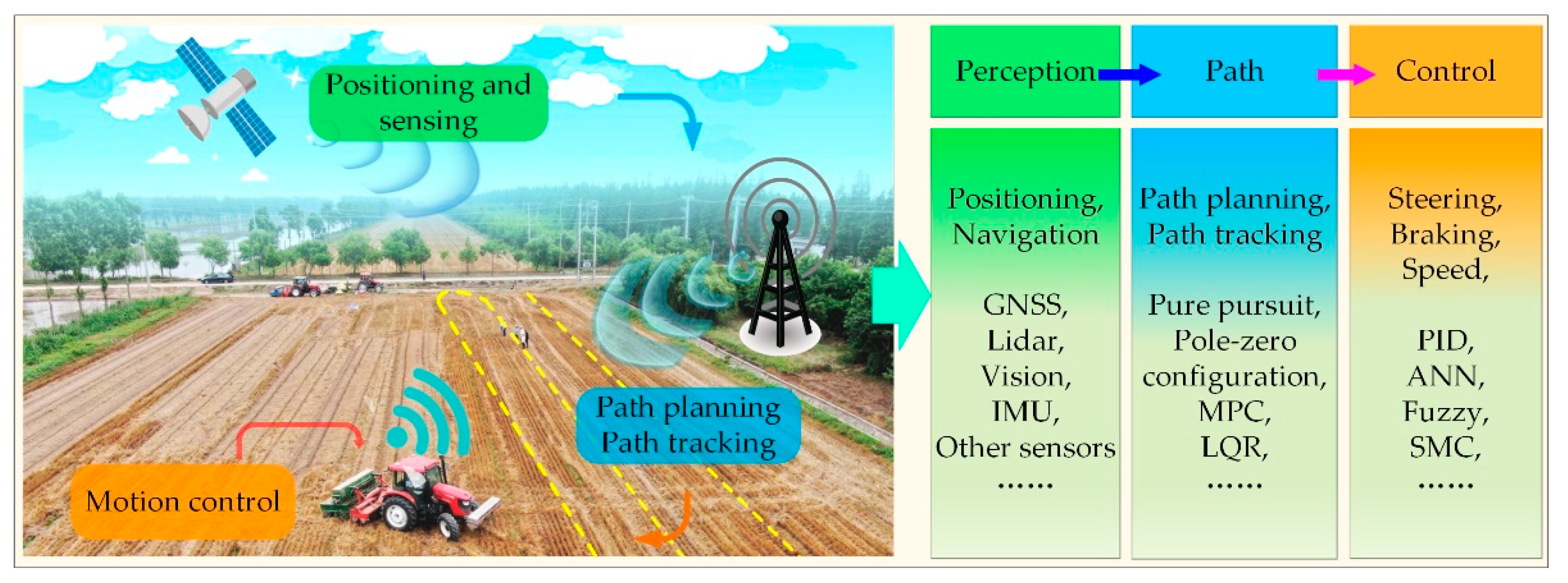
Figure 1. Sketch diagram of key autonomous navigation technologies of UATs.
Preprints 98339 g001
Figure 2. Diagram of the principle of differential positioning technology [12].
Preprints 98339 g002
Figure 3. Autonomous driving system and load platform: (a) Dongfeng DF1004-2 experimental platform [13]; (b) JD1204 Qianxun Findcm GNSS RTK receiver experimental platform [14].
Preprints 98339 g003
Figure 4. Typical components of UAT systems: (a) DF2204 unmanned tractor with CVT and GNSS [18]; (b) PL60-4LZT-6Z crawler combine harvester [19]; (c) Components of an autonomous GNSS land leveler system [20]; (d) MTI-300 inertial navigation system; (e) DF2004-5A transplanter [21]; (f) AF300 tractor [22].
Preprints 98339 g004
Figure 5. Machine vision-based perception device for autonomous navigation (a) Unmanned ground vehicle [28]; (b) Unmanned robot [29]; (c) Unmanned crawler tractor [31].
Preprints 98339 g005
Figure 6. Unmanned tractor-trailer with a laser range finder (a) and its navigation scheme (b) [32].
Preprints 98339 g006
Figure 7. Combination of inertial and satellite navigation systems in UATs.
Preprints 98339 g007
Figure 8. A field robot with an integrated IMU and GNSS system (a) and the navigation scheme (b) [37].
Preprints 98339 g008
Figure 9. Operation state perception system: (a) An electric-hydraulic system for a flexible tine [46]; (b) Precision fertilization control system [47].
Preprints 98339 g009
Figure 10. Path planning routes of UATs: (a) Turning methods; (b) Field routes.
Preprints 98339 g010
Figure 11. Classification of path planning algorithms.
Preprints 98339 g011
Figure 12. Schematic diagram of path planning based on different algorithms: (a) The improved RRT algorithm [52]; (b) Improved ant colony algorithm [54]; (c) Flowchart and path planning of the nested method [55].
Preprints 98339 g012
Figure 13. Motion models of UATs: (a) Linearized bicycle model [60]; (b) Two-wheel vehicle model [61]; (c) Kinematic model of four-wheel steered vehicle [62]. .
Preprints 98339 g013
Figure 14. Pure pursuit control model [63].
Preprints 98339 g014
Figure 15. Framework of path tracking algorithm [66].
Preprints 98339 g015
Figure 16. Control scheme diagram of the MPC method for UAT [68].
Preprints 98339 g016
Figure 17. Diagram of the linear quadratic regulator (LQR) control principle.
Preprints 98339 g017
Figure 19. Structure of a typical control system for the autonomous navigation of UAT.
Preprints 98339 g019
Figure 20. Diagram of the (a) steering control module and (b) the steering angle detection module of UAT [88].
Preprints 98339 g020
Figure 21. Schematic diagrams of a steering system for UATs: (a) Hydraulic servo control system [92]; (b) Coupled electro-hydraulic steering system [93].
Preprints 98339 g021
Figure 22. (a) NI CompactDAQ 9862 single port (left) and Vector CANcaseXL dual port (right) [99]; (b) CAN network topology diagram for a UAT [100].
Preprints 98339 g022
Table 1. Perception methods for the operational states of agricultural machinery.
Operation State Perception Method Advantages Disadvantages
Vehicle Speed[41] Radar speedometer, ground wheel, and GPS Accurate ground wheel measurements at low speeds, accurate radar and GPS measurements at high speeds [42] Inability to achieve high detection accuracy from low to high speeds
Tillage
Depth[43]
Indirect detection using dual inclinometers, depth measurement using suspension angle sensors Overcoming errors caused by field residue coverage and machinery vibration Indirect calculation of tillage depth based on complex mathematical models with limited universality
Seeding Depth[44] Combination of angle sensors and ultrasonic sensors High stability and accuracy Specific to the type of seed unit
Fertilizer
Application[45]
Capacitance and electrostatic induction Correlation between fertilizer flow rate and output signal Accuracy influenced by particle size and flow rate
Disclaimer/Publisher’s Note: The statements, opinions and data contained in all publications are solely those of the individual author(s) and contributor(s) and not of MDPI and/or the editor(s). MDPI and/or the editor(s) disclaim responsibility for any injury to people or property resulting from any ideas, methods, instructions or products referred to in the content.
Copyright: This open access article is published under a Creative Commons CC BY 4.0 license, which permit the free download, distribution, and reuse, provided that the author and preprint are cited in any reuse.
Prerpints.org logo

Preprints.org is a free preprint server supported by MDPI in Basel, Switzerland.

Subscribe

© 2024 MDPI (Basel, Switzerland) unless otherwise stated