Submitted:
07 February 2024
Posted:
09 February 2024
You are already at the latest version
Abstract
Keywords:
1. Introduction
2. Basic models and methods
2.1. Nanoscale two-dimensional and polymer ferroelectric thin films
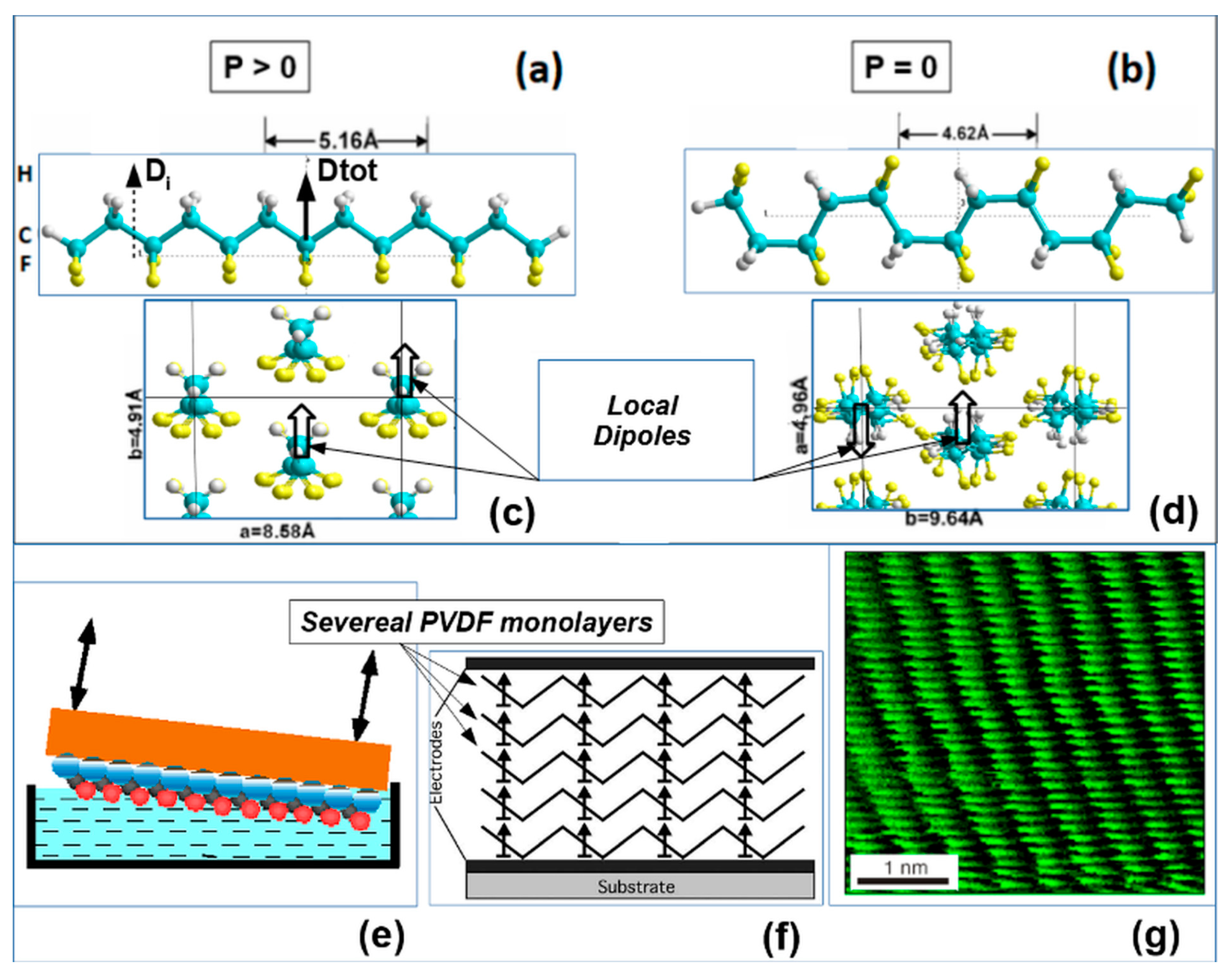
2.2. Main Theoretical Approach
2.2.1. Main Features of the LGD Theory for Nanoscale Ferroelectrics
2.2.2. Main theoretical approach description
2.3. Main models, methods and computational details for thin polymer ferroelectric films
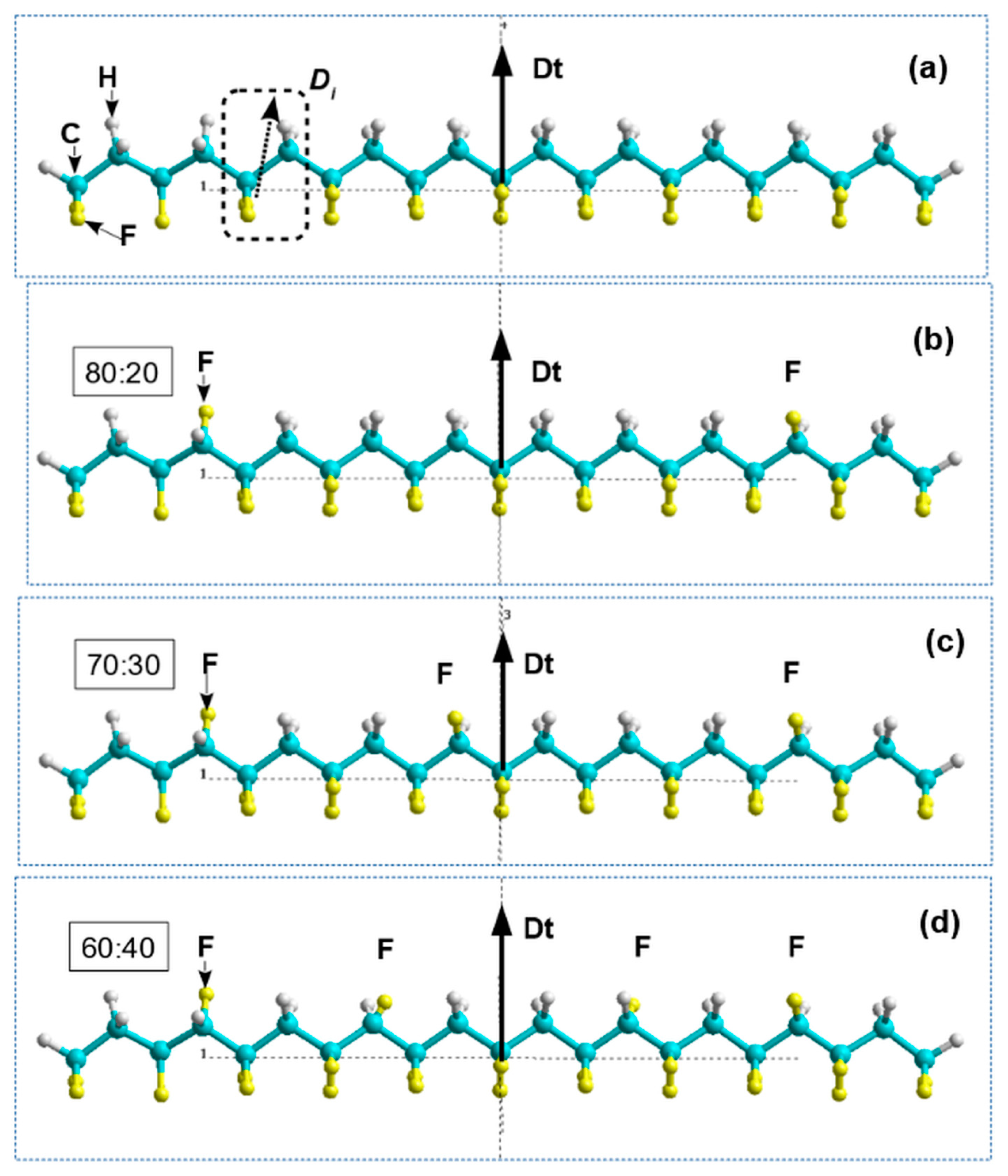
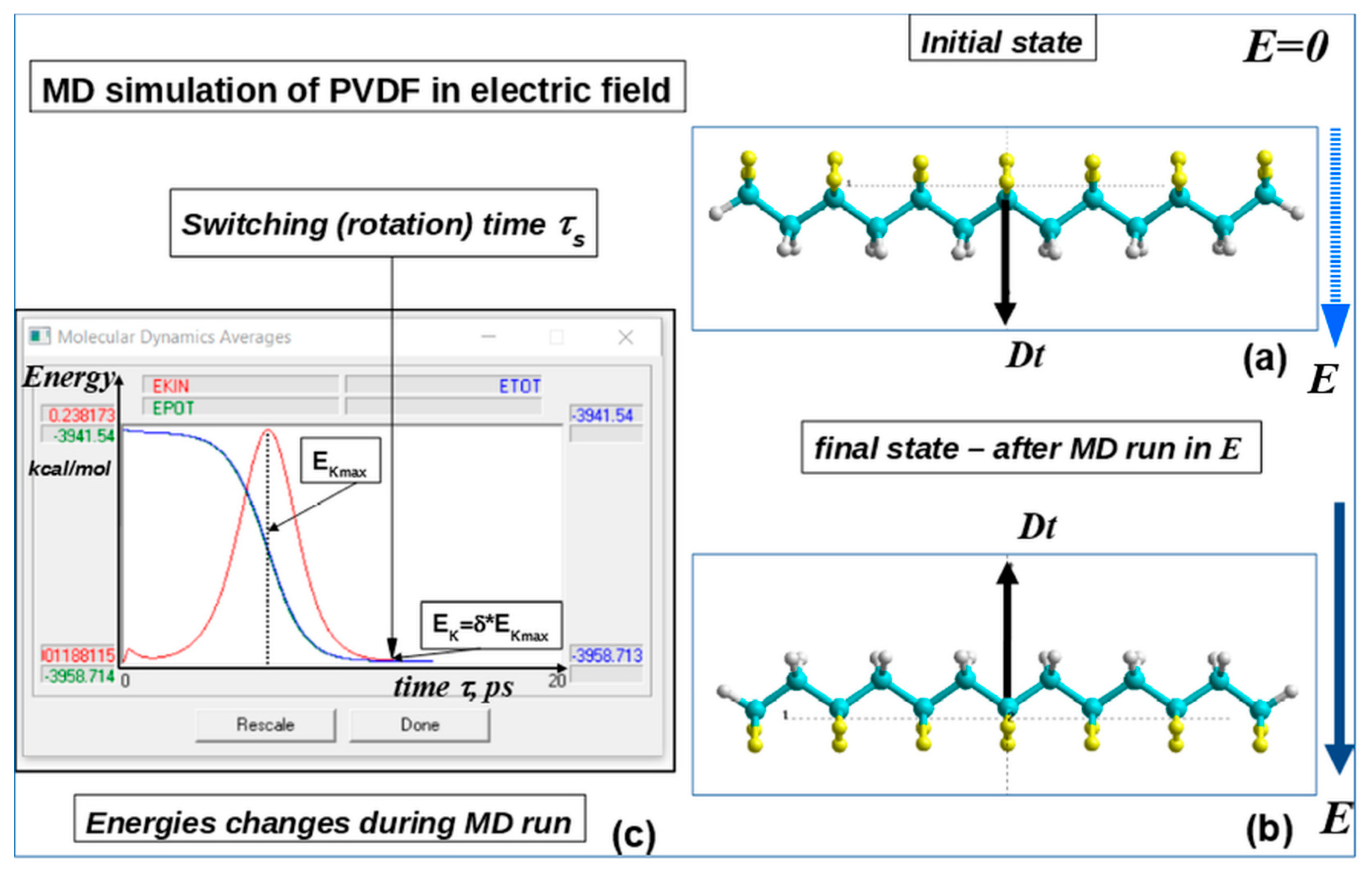
3. Results
3.1. Homogeneous polarization switching in polymer ferroelectrics by MDS method
3.2. Polarization switching in a heterostructure consisting of PVDF and graphene layers
3.2.1. Main details
3.2.2. Results
3.2.3. The possible reasons for the graphene layers influence on switching times
3.3. Polarization switching in PVDF-TrFE
3.3.1. Main details
3.3.2. Results
3.4. Polarization switching in a heterostructure consisting of PVDF-TrFE and graphene layers
3.4.1. Main details
3.4.2. Results
4. Conclusions
Author Contributions
Funding
Institutional Review Board Statement
Informed Consent Statement
Acknowledgments
Conflicts of Interest
References
- Mohammadpourfazeli, S.; Arash, S.; Ansari, A.; Yang, S.; Mallick, K.; Bagherzaden, R. Future prospects and recent developments of polyvinylidene fluoride (PVDF) piezoelectric polymer; fabrication methods, structure, and electro-mechanical properties. RSC Advances 2023, 13, 370–387. [Google Scholar] [CrossRef]
- Mai, M.; Ke, S.; Lin, P.; Zeng, X. Ferroelectric Polymer Thin Films for Organic Electronics. J. of Nanomaterials 2015, 2015, 812538. [Google Scholar] [CrossRef]
- Yan, M.; Liu, S.; Liu, Y.; Xiao, Z.; Yuan, X.; Zhai, D.; Zhou, K.; Wang, Q.; Zhang, D.; Bowen, C.; Zhang, Y. Flexible PVDF-TrFE Nanocomposites with Ag-decorated BCZT Heterostructures for Piezoelectric Nanogenerator Applications. ACS Appl Mater Interfaces. 2022, 14, 53261–53273. [Google Scholar] [CrossRef]
- Huang, T.; Yang, S.; He, P.; Sun, J.; Zhang, S.; Li, D.; Meng, Y.; Zhou, J.; Tang, H.; Liang, J.; Ding, G.; Xie, X. Phase-Separation-Induced PVDF/Graphene Coating on Fabrics toward Flexible Piezoelectric Sensors. ACS Applied Materials & Interfaces. 2018, 10. [Google Scholar] [CrossRef]
- Shi, L.; Hu, Z.; Hong, Y. PVDF-supported graphene foam as a robust current collector for lithium metal anodes. RSC Adv. 2020, 10, 20915–20920. [Google Scholar] [CrossRef]
- Park, B.E. Non-volatile Ferroelectric Memory Transistors Using PVDF and P(VDF-TrFE) Thin Films. In Ferroelectric-Gate Field Effect Transistor Memories. Topics in Applied Physics; Park, BE., Ishiwara, H., Okuyama, M., Sakai, S., Yoon, SM., Eds.; Springer: Dordrecht, Netherlands, 2016; Volume 131. [Google Scholar] [CrossRef]
- Kamberaj, H. Molecular Dynamics Simulations in Statistical Physics: Theory and Applications; Springer Nature Switzerland AG: Cham, Switzerland, 2020. [Google Scholar]
- Hollingsworth, S.A.; Dror, R.O. Molecular dynamics Simulation for All. Neuron 2018, 99, 1129–1143. [Google Scholar] [CrossRef]
- Grigoriev, F.V.; Sulimov, V.B.; Tikhonravov, A.V. Molecular Dynamics Simulation of Laser Induced Heating of Silicon Dioxide Thin Films. Nanomaterials 2021, 11, 2986. [Google Scholar] [CrossRef] [PubMed]
- Bystrov, V.S. Molecular modeling and molecular dynamic simulation of the polarization switching phenomena in the ferroelectric polymers PVDF at the nanoscale. Physica B: Condensed Matter 2014, 432, 21–25. [Google Scholar] [CrossRef]
- Fridkin, V.M.; Ducharme, S. Ferroelectricity at the Nanoscale. Basic and Applications, 1st ed.; Springer: New York, NY, USA, 2014. [Google Scholar]
- Bystrov, V.S.; Fridkin, V.M. Two-dimensional ferroelectrics and homogeneous switching. To the 75th anniversary of the Landau—Ginzburg theory of ferroelectricity. Phys. Usp. 2020, 63, 417–439. [Google Scholar] [CrossRef]
- Paramonova, E.V.; Bystrov, V.S.; Meng, X.; Shen, H.; Wang, J.; Fridkin, V.M. Polarization Switching in 2D Nanoscale Ferroelectrics: Computer Simulation and Experimental Data Analysis. Nanomaterials 2020, 10, 1841. [Google Scholar] [CrossRef]
- Paramonova, E.V.; Bystrov, V.S.; Meng, X.; Shen, H.; Wang, J.; Fridkin, V.M. Polarization switching in nanoscale ferroelectrics. Ferroelectrics 2021, 575, 103–116. [Google Scholar] [CrossRef]
- Bystrov, V.S.; Fridkin, V.M. Domain and homogeneous switching in ferroelectrics. On the 75th anniversary of the Landau–Ginzburg theory of ferroelectricity. Ferroelectrics 2020, 569, 164–181. [Google Scholar] [CrossRef]
- Lines, M.E.; Glass, A.M. Principles and applications of ferroelectrics and related materials; Clarendon Press: Oxford, USA, 1977. [Google Scholar]
- Bune, A.V.; Fridkin, V.M.; Ducharme, S.; Blinov, L.M.; Palto, S.P.; Sorokin, A.V.; Yudin, S.G.; Zlatkin, A. Two-dimensional ferroelectric films. Nature 1998, 391, 874–877. [Google Scholar] [CrossRef]
- Palto, S.; Blinov, L.; Bune, A.; Dubovik, E.; Fridkin, V.; Petukhova, N.; Verkhovskaya, K.; Yudin, S. Ferroelectric Langmuir-Blodgett films. Ferroelectr. Lett. 1995, 19, 65–68. [Google Scholar] [CrossRef]
- Bune, A.; Ducharme, S.; Fridkin, V.; Blinov, L.; Palto, S.; Petukhova, N.; Yudin, S. Novel switching phenomena in ferroelectric Langmuir–Blodgett films. Appl. Phys. Lett. 1995, 67, 3975. [Google Scholar] [CrossRef]
- Palto, S.; Blinov, L.; Bune, A.; Dubovik, E.; Fridkin, V.; Petukhova, N.; Verkhovskaya, K.; Yudin, S. Ferroelectric Langmuir-Blodgett films. Ferroelectrics 1996, 184, 127–129. [Google Scholar] [CrossRef]
- Blinov, L.M.; Fridkin, V.M.; Palto, S.P.; Bune, A.V.; Dowben, P.A.; Ducharme, S. Two-dimensional ferroelectrics. Phys. Usp. 2000, 43, 243–257. [Google Scholar] [CrossRef]
- Fridkin, V.M.; Ducharme, S. Ferroelectricity at the nanoscale. Phys. Usp. 2014, 57, 597–603. [Google Scholar] [CrossRef]
- Bystrov, V.; Bdikin, I.; Silibin, M.; Meng, X.; Tian, B.; Wang, J.; Karpysky, D.; Bystrova, A.; Paramonova, E. Ferroelectric PVDF Films and Graphene-based Composites. Journal of Physics: Conference Series 2018, 1053, 012043. [Google Scholar] [CrossRef]
- Bystrov, V.S.; Bdikin, I.K.; Silibin, M.V.; Karpinsky, D.V.; Kopyl, S.; Goncalves, G.; Sapronova, A.V.; Kuznetsova, T.; Bystrova, V.V. Graphene/graphene oxide and polyvinylidene fluoride polymer ferroelectric composites for multifunctional applications. Ferroelectrics 2017, 509, 124–142. [Google Scholar] [CrossRef]
- Silibin, M.V.; Bystrov, V.S.; Karpinsky, D.V.; et al. Local mechanical and electromechanical properties of the P(VDF-TrFE)-graphene oxide thin films. Applied Surface Science 2017, 421 Part A, 42–51. [Google Scholar] [CrossRef]
- Silibin, M.; Karpinsky, D.; Bystrov, V.; et al. Preparation, Stability and Local Piezoelectrical Properties of P(VDF-TrFE)/Graphene Oxide Composite Fibers. C - Journal of Carbon Research 2019, 5, 48. [Google Scholar] [CrossRef]
- Novoselov, K.S.; Geim, A.K.; Morozov, S.V.; Jiang, D.; Zhang, Y.; Dubonos, S.V.; et al. Electric Field Effect in Atomically Thin Carbon Films. Science 2004, 306, 666–669. [Google Scholar] [CrossRef] [PubMed]
- Geim, A.K. Graphene: status and prospects. Science 2009, 324, 1530–1534. [Google Scholar] [CrossRef] [PubMed]
- Winsberg, E. Computer Simulations in Science. The Stanford Encyclopedia of Philosophy (Spring 2019 Edition). Edward, N.Z., Ed.; Available online: https://plato.stanford.edu/archives/spr2019/entries/simulations-science/.
- Ramachandran, K.I.; Deepa, G.; Namboori, K. Computational chemistry and molecular modeling: Principles and applications; Springer-Verlag: Berlin/Heidelberg, Germany, 2008. [Google Scholar] [CrossRef]
- Szabo, A.; Ostlund, N. Modern Quantum Chemistry; Macmillan: New York, NY, USA, 1985. [Google Scholar]
- Clark, T.A. Handbook of Computational Chemistry; John Wiley and Sons: New York, NY, USA, 1985. [Google Scholar]
- Pople, J.A.; Beveridge, D.L. Approximate Molecular Orbital Theory; McGraw-Hill, 1970. [Google Scholar]
- Stewart, J.J.P. Optimization of Parameters for Semiempirical Methods. I. Method. J. Comput. Chem. 1989, 10, 209–220. [Google Scholar] [CrossRef] [PubMed]
- Stewart, J.J.P. Optimization of parameters for semiempirical methods II. Applications. J. Comput. Chem. 1989, 10, 221–264. [Google Scholar] [CrossRef]
- Stewart, J.J.P. Optimization of parameters for semiempirical methods V: modification of NDDO approximations and application to 70 elements. J. Mol. Mod. 2007, 13, 1173–1213. [Google Scholar] [CrossRef] [PubMed]
- Rezac, J.; Hobza, P. Advanced Corrections of Hydrogen Bonding and Dispersion for Semiempirical Quantum Mechanical Methods. J. Chem. Theory Comput. 2012, 8, 141–151. [Google Scholar] [CrossRef] [PubMed]
- HyperChem, Versions 8.0/01, Tools for Molecular Modeling. Professional Edition For Windows AC Release 8.0 USB (on CD); Hypercube. Inc.: Gainesville, FL, USA, 2011; p. 32601.
- Bystrov, V.; Bystrova, N.; Paramonova, E.; Sapronova, A. Computational nanostructures and physical properties of the ultra-thin ferroelectric Langmuir-Blodgett films. Ferroelectric Letters 2006, 33, 153–162. [Google Scholar] [CrossRef]
- Bystrov, V.S.; Bystrova, N.K.; Paramonova, E.V.; Vizdrik, G.; Sapronova, A.V.; Kuehn, M.; Kliem, H.; Kholkin, A.L. First principle calculations of molecular polarization switching in P(VDF–TrFE) ferroelectric thin Langmuir–Blodgett films. J. Phys: Condens. Matter. 2007, 19, 456210. [Google Scholar] [CrossRef]
- Bystrov, V.S.; Bdikin, I.K.; Kiselev, D.A.; Yudin, S.G.; Fridkin, V.M.; Kholkin, A.L. Nanoscale polarization patterning of ferroelectric Langmuir-Blodgett P(VDF-TrFE) films. J. Phys. D: Appl. Phys. 2007, 40, 4571–4577. [Google Scholar] [CrossRef]
- Bystrov, V.S.; Dekhtyar, Yu.; Paramonova, E.; Pullar, R.; Katashev, A.; et al. Polarization of PVDF and P(VDF- TrFE) thin films revealed by emission spectroscopy with computational simulation during phase transition. J. Appl. Phys. 2012, 111, 104113. [Google Scholar] [CrossRef]
- Gevorkyan, V.E.; Paramonova, E.V.; Avakyan, L.A.; Bystrov, V.S. Computer modeling and molecular dynamics of polarization switching in the ferroelectric films PVDF and P(VDF-TrFE) on nanoscale. Mathematical Biology and Bioinformatics 2015, 10, 131–153. [Google Scholar] [CrossRef]
- Paramonova, E.V.; Filippov, S.V.; Gevorkyan, V.E.; Avakyan, L.A.; Meng, X.J.; Tian, B.B.; Wang, J.L.; Bystrov, V.S. Polarization switching in ultrathin polyvinylidene fluoride homopolymer ferroelectric films. Ferroelectrics 2017, 509, 143–157. [Google Scholar] [CrossRef]
- Haghighi, S.; Ansari, R.; Ajori, S. A molecular dynamics study on the interfacial properties of carbone-functionalized graphene/polymer nanocomposites. Int. J. Mech. Mater. Des. 2020, 16, 387–400. [Google Scholar] [CrossRef]
- Safina, L.R.; Baimova, J.A.; Krylova, K.A.; Murzaev, R.T.; Mulyukov, R.R. Simulation of metal-graphene composites by molecular dynamics: a review. Lett. Mater. 2020, 10, 351–360. [Google Scholar] [CrossRef]
- Bystrov, V.S.; Paramonova, E.V.; Bdikin, I.K.; et al. Molecular modelling of the piezoelectric effect in the ferroelectric polymer poly(vinylidene fluoride) (PVDF). J. Mol. Mod. 2013, 19, 3591–3602. [Google Scholar] [CrossRef] [PubMed]
- Bystrov, V.S.; Bdikin, I.K.; Silibin, M.; et al. Molecular modeling of the piezoelectric properties of ferroelectric composites containing polyvinylidene fluoride (PVDF) and either graphene or graphene oxide. J. Mol. Mod. 2017, 23, 128. [Google Scholar] [CrossRef]
- Bystrov, V.S.; Bdikin, I.K.; Silibin, M.V.; Meng, X.J.; Lin, T.; Wang, J.L.; et al. Pyroelectric properties of the ferroelectric composites based on the polyvinylidene fluoride (PVDF) with graphene and graphene oxide. Ferroelectrics 2019, 541, 17–24. [Google Scholar] [CrossRef]
- Bystrov, V.S.; Paramonova, E.V.; Meng, X.; Shen, H.; Wang, J.; Fridkin, V.M. Polarization switching in nanoscale ferroelectric composites containing PVDF polymer film and graphene layers. Ferroelectrics 2022, 590, 27–40. [Google Scholar] [CrossRef]
- Kliem, H.; Tadros-Morgane, R. Extrinsic versus intrinsic ferroelectric switching: Experimental investigations using ultra-thin PVDF Langmuir–Blodgett films. J. Phys. D: Appl. Phys. 2005, 38, 1860–1868. [Google Scholar] [CrossRef]
- Tagantsev, A.K.; Cross, L.E.; Fousek, J. Domains in Ferroelectric Crystals and Thin Films; Springer: New York, NY, USA, 2010. [Google Scholar]
- Ducharme, S.; Fridkin, V.M.; Bune, A.V.; Palto, S.P.; Blinov, L.M.; Petukhova, N.N.; Yudin, S.G. Intrinsic Ferroelectric Coercive Field. Phys. Rev. Lett. 2000, 84, 175. [Google Scholar] [CrossRef] [PubMed]
- Ginzburg, V.L. On the dielectric properties of ferroelectric (seignetteelectric) crystals and barium titanate. Zh. Eksp. Teor. Fiz. 1945, 15, 739–750. [Google Scholar]
- Ginzburg, V.L. On polarization and piezoelectric effect of barium titanate near the point of ferroelectric transition. Zh. Eksp. Teor. Fiz. 1949, 19, 36–41. [Google Scholar]
- Landau, L.D. On the theory of phase transitions. [Phys. Z. Sowjet. 1937, 11, 545.]. Nature 1936, 138, 840–841. [Google Scholar]
- Landau, L.D.; Khalatnikov, I.M. On the anomalous absorption of sound near a second-order phase transition point. Dokl. Akad. Nauk SSSR 1954, 96, 469. [Google Scholar]
- Vizdrik, G.; Ducharme, S.; Fridkin, V.M.; Yudin, S.G. Kinetic of ferroelectric switching in ultrathin films. Phys. Rev. B 2003, 68, 094113. [Google Scholar] [CrossRef]
- Ievlev, A.; Verkhovskaya, K.; Fridkin, V. Landau-Khalatnikov switching kinetics in the ferroelectric copolymers nanostructures. Ferroelectr. Lett. 2006, 33, 147–152. [Google Scholar] [CrossRef]
- Gaynutdinov, R.V.; Mitko, S.; Yudin, S.G.; Fridkin, V.M.; Ducharme, S. Polarization switching at the nanoscale in ferroelectric copolymer thin films. Appl. Phys. Lett. 2011, 99, 142904. [Google Scholar] [CrossRef]
- Gaynutdinov, R.; Yudin, S.; Ducharme, S.; Fridkin, V. Homogeneous switching in ultrathin ferroelectric films. J Phys: Condens Matter. 2012, 24, 015902. [Google Scholar] [CrossRef]
- Wang, J.L.; Liu, B.L.; Zhao, X.L.; Tian, B.B.; Zou, Y.H.; Sun, S.; Shen, H.; Sun, J.L.; Meng, X.J. and Chu, J.H. Transition of the polarization switching from extrinsic to intrinsic in the ultrathin polyvinylidene fluoride homopolymer films. Appl. Phys. Lett. 2014, 104, 182907. [Google Scholar] [CrossRef]
- Yin, Z.; Tian, B.; Zhu, Q.; Duan, C. Characterization and Application of PVDF and Its Copolymer Films Prepared by Spin-Coating and Langmuir–Blodgett Method. Polymers 2019, 11, 2033. [Google Scholar] [CrossRef]
- Cardoso, V.F.; Costa, C.M.; Minas, G.; Lanceros-Mendez, S. Improving the optical and electroactive response of poly(vinylidene fluoride-trifluoroethylene) spin-coated films for sensor and actuator applications. Smart Mater. Struct. 2012, 21, 085020. [Google Scholar] [CrossRef]
- Dawson, N.M.; Atencio, P.M.; Malloy, K.J. Facile deposition of high quality ferroelectric poly(vinylidene fluoride) thin films by thermally modulated spin coating. J. Polym. Sci. Part B Polym. Phys. 2017, 55, 221–227. [Google Scholar] [CrossRef]
- Gaynutdinov, R.; Minnekaev, M.; Mitko, S.; Tolstikhina, A.; Zenkevich, A.; Ducharme, S.; Fridkin, V. Polarization switching kinetics in ultrathin ferroelectric barium titanate film. Physica B: Condensed Matter 2013, 424, 8–12. [Google Scholar] [CrossRef]
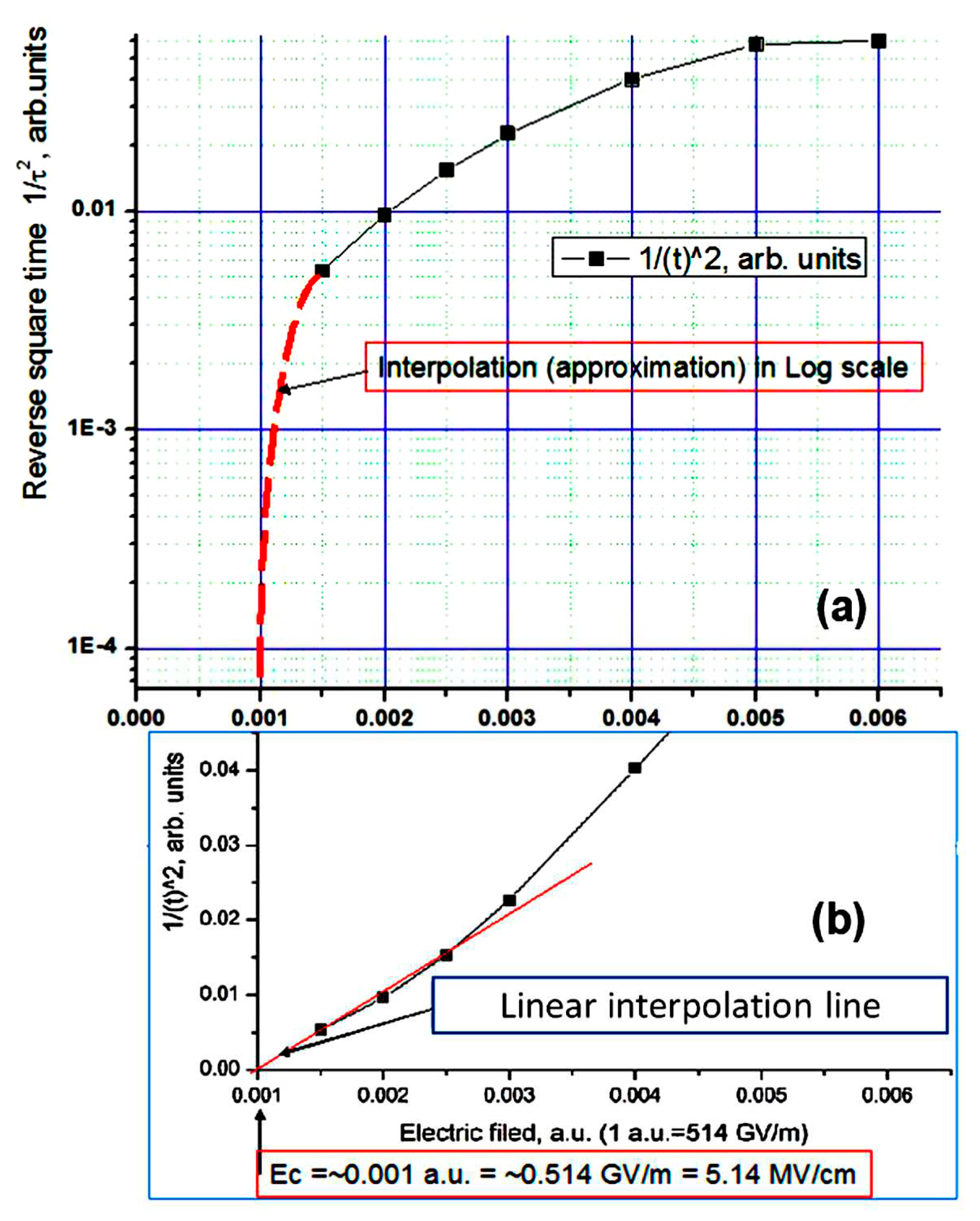
Disclaimer/Publisher’s Note: The statements, opinions and data contained in all publications are solely those of the individual author(s) and contributor(s) and not of MDPI and/or the editor(s). MDPI and/or the editor(s) disclaim responsibility for any injury to people or property resulting from any ideas, methods, instructions or products referred to in the content. |
© 2024 by the authors. Licensee MDPI, Basel, Switzerland. This article is an open access article distributed under the terms and conditions of the Creative Commons Attribution (CC BY) license (http://creativecommons.org/licenses/by/4.0/).


