1. Introduction
Prefabricated rebar cages are widely used in construction of reinforced concrete structures, including bridge piers, large columns, and cast-in-drilled-hole piles. These cages are typically composed of longitudinal and transverse reinforcing bars that are connected using tie-wire connections. Experimental-analytical research conducted by Builes-Mejia et al. [
1] has shown that the failure of rebar cages is governed by the tie-wire connection failure, which renders tie-wires as the "weak links" in the rebar cage structural system. As a result, alternative methods for connecting the rebars have been explored, such as the application of mechanical connectors.
Mechanical U-bolt connector, or simply U-bolt, is a type of reliable connection introduced by Vahedi et al. [
2,
3,
4] for application in rebar cages. The mechanical properties of U-bolt have been established through a series of experimental tests. Unlike traditional tie-wires, U-bolts provide robust and secure connections, improving the stability of rebar cages [
2,
5]. Full-scale testing and numerical modeling were performed to investigate the system-level performance of rebar cages reinforced with U-bolt connectors under common site handling conditions (i.e., lifting and tilting) [
4]. Results show that replacing tie-wire connections with mechanical U-bolt connectors on 2-3% of rebar intersections with a specific pattern can effectively increase the stability and safety of rebar cages during common site handling conditions, significantly reducing the vulnerability and risk of failure of rebar cages.
Cage Clamp is another type of mechanical connector that can be used in rebar cages. Similar to U-bolts, Cage Clamp is designed to provide a robust and secure crossbar connection in rebar cages. Cage Clamp offers advantages in terms of installation simplicity and efficiency. Unlike U-bolts, which consist of two plates and four bolts, the Cage Clamp features a streamlined design with just one plate and two bolts (see
Figure 1). This results in quick assembly, reduced material cost, and reduced labor time compared to the U-bolts. The present study focuses on the application of Cage Clamp mechanical connector for application in rebar cages. To this end, a series of component-level experimental tests are conducted to determine mechanical properties and force-deformation responses of Cage Clamp connection in different degrees of freedom (DOFs). Subsequently, full-scale tests are performed to examine the behavior of rebar cages reinforced with Cage Clamp connectors under common site handling conditions such as lifting and tilting. Finally, the data obtained from experimental tests are used to develop, calibrate, and validate 3D Finite Element (FE) numerical models that can predict the response behavior of rebar cages with Cage Clamp connectors. Using the numerical model, a sensitivity analysis is performed to assess the effect of the number of Cage Clamps on the deflection and stability of rebar cages during cage lifting process.
2. Component-Level Experimental Tests
2.1. Test Setup
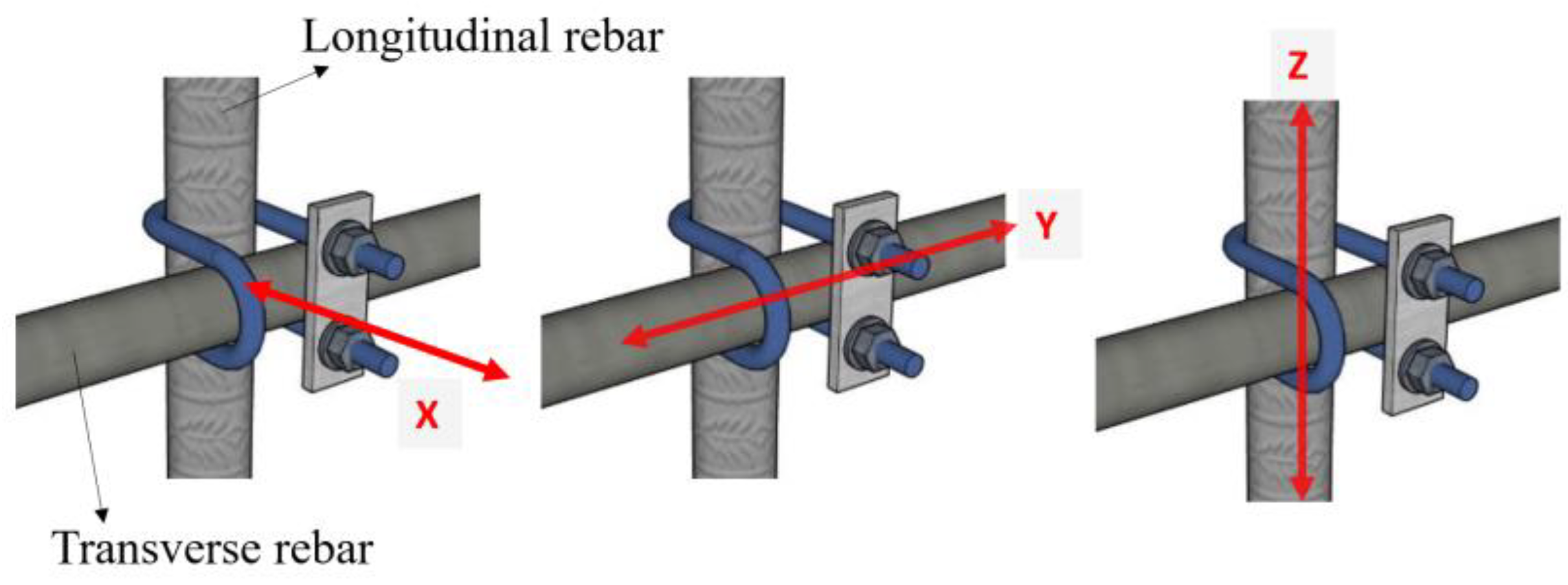
A set of experiments was conducted to determine the force-deformation responses of Cage Clamp connection in different degrees of freedom (DOFs) for crossbar connections. To specify the DOFs at a crossbar connection, a local coordinate system is defined, and DOFs in the X, Y, and Z directions are specified as illustrated in
Figure 2. The X-axis is perpendicular to the longitudinal and transverse bar directions, the Y-axis is parallel to the transverse bar direction, and the Z-axis is in line with the longitudinal bar direction.
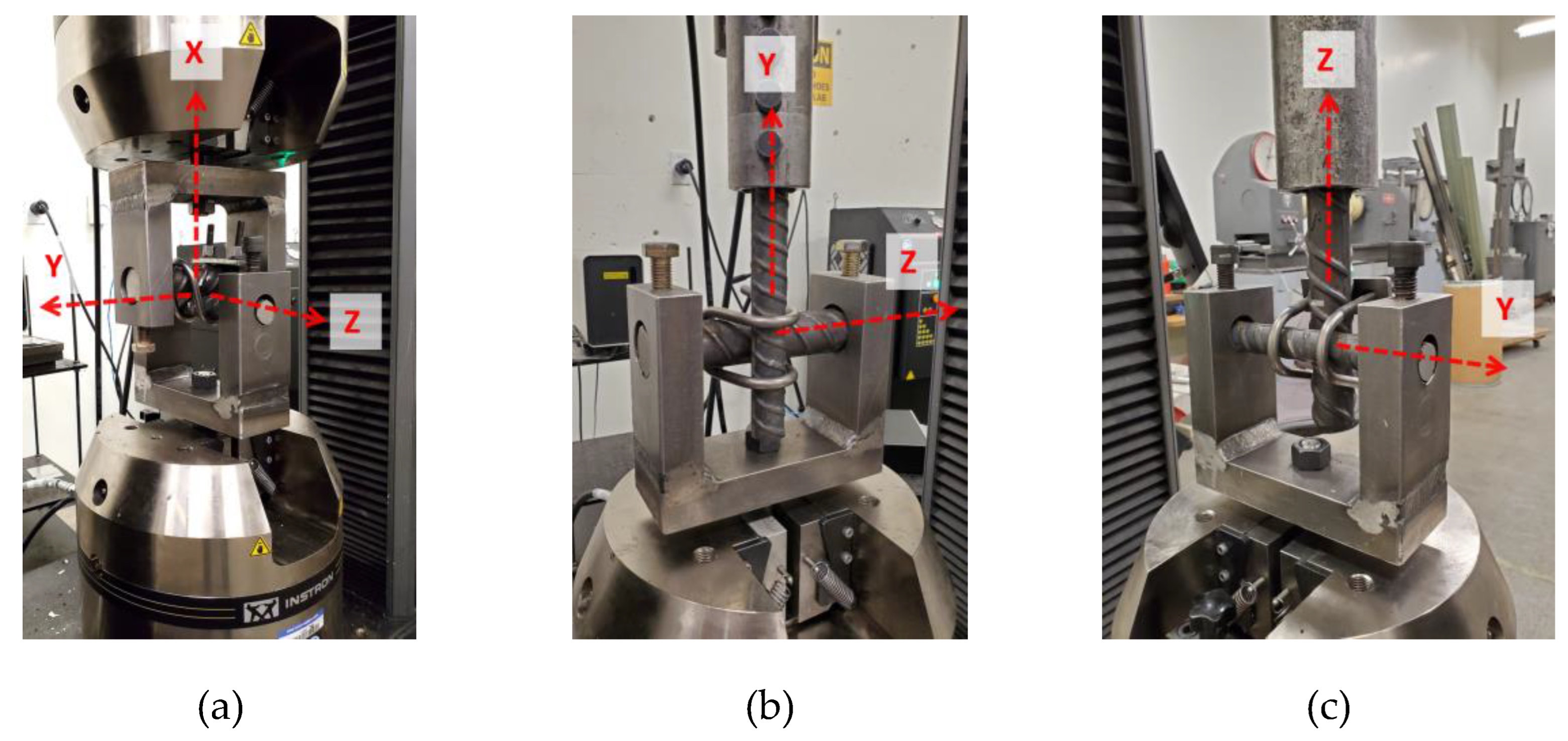
To carry out the tests in different DOFs, testing fixtures comprising C-shaped frames and a vertical fixture were designed and constructed, as depicted in
Figure 3. The C-shaped frames allowed for easy insertion and removal of rebars after each test. The vertical fixtures were fabricated using a bar-lock (D250L bar-lock manufactured by Dayton Superior) welded to a coupler nut, which allowed for easy removal and replacement of rebars. The C-shaped frame and vertical fixtures were then connected to the grips of an Instron 5985 Universal Testing Machine.
For testing Cage Clamp in the X-direction, two C-shaped frames were utilized, with one frame holding the longitudinal rebar and the other holding the transverse rebar, as shown in
Figure 3a. The Instron Machine was used to hold the lower frame fixed and pull the upper frame monotonically in a displacement-controlled mode at a rate of 0.13 mm per second. To test Cage Clamp connector in the Y-direction, a vertical fixture was employed, as shown in
Figure 3b. In this case, the C-shaped frame held the longitudinal rebar and was connected to the fixed grip of the Instron machine, while the transverse rebar was connected to the moving grip via the vertical fixture. In order to conduct tests in the Z-direction, the C-shaped frame securely holds the transverse rebar in place while the longitudinal rebar being pulled by the vertical fixture, as illustrated in
Figure 3c. During the experiments, the force was measured using the internal load cell sensor of the Instron machine, while the connector deformation was measured using a synchronized MTS LX500 laser extensometer that utilized laser beams to measure the relative displacement between two reflectors installed on the test specimen.
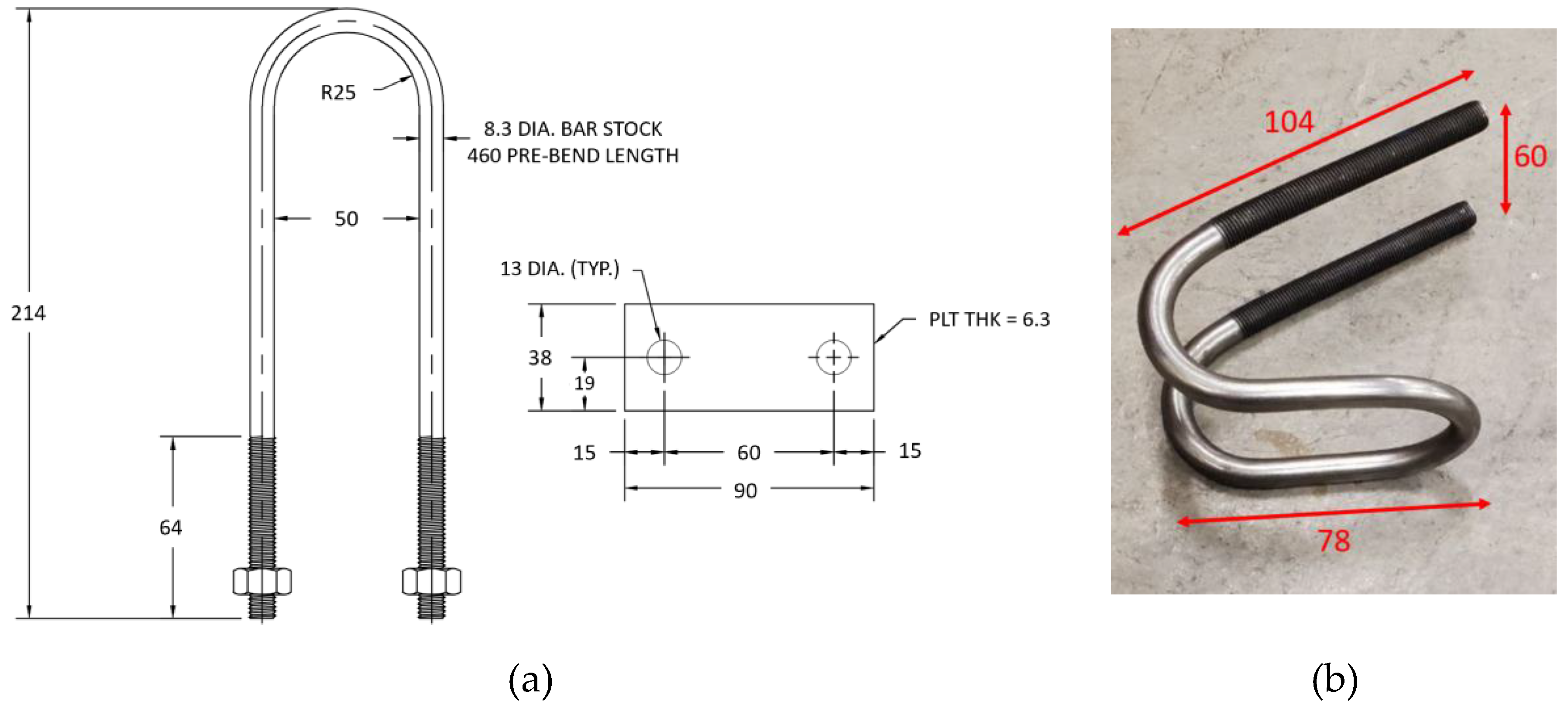
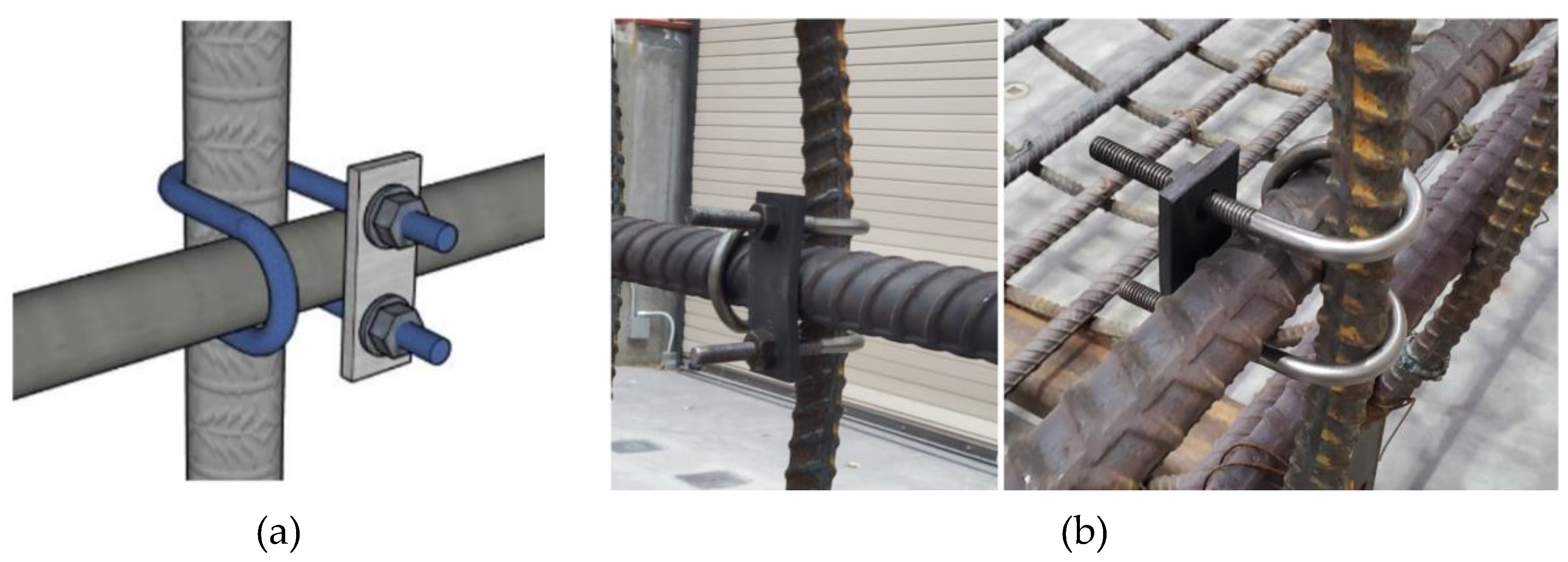
The Cage Clamp connector consists of a U-bolt with elongated bent legs, as shown in
Figure 4a and b. The dimensions of the Cage Clamp and plate are illustrated in
Figure 4a; these dimensions are for testing #11 longitudinal bars (equivalent to Φ36 metric) and #8 transverse bars (equivalent to Φ25 metric). By changing the bent curvature of the U-bolt, the connector can be manufactured for other sizes of longitudinal rebar. Cage Clamp material has a minimum yield stress of 720 MPa, and the plates are made of A36 steel. To ensure a proper connection fit, the nuts were tightened until the plates bent at approximately 5 degrees, which is approximately equivalent to 100 N.m of torque on the bolts.
Figure 3.
Test setup in (a) X-direction, (b) Y-direction, and (c) Z-direction.
Figure 3.
Test setup in (a) X-direction, (b) Y-direction, and (c) Z-direction.
Figure 4.
Cage Clamp connector and plate details: (a) dimensions, (b) actual view (dimensions are in mm).
Figure 4.
Cage Clamp connector and plate details: (a) dimensions, (b) actual view (dimensions are in mm).
2.2. Results and Discussions
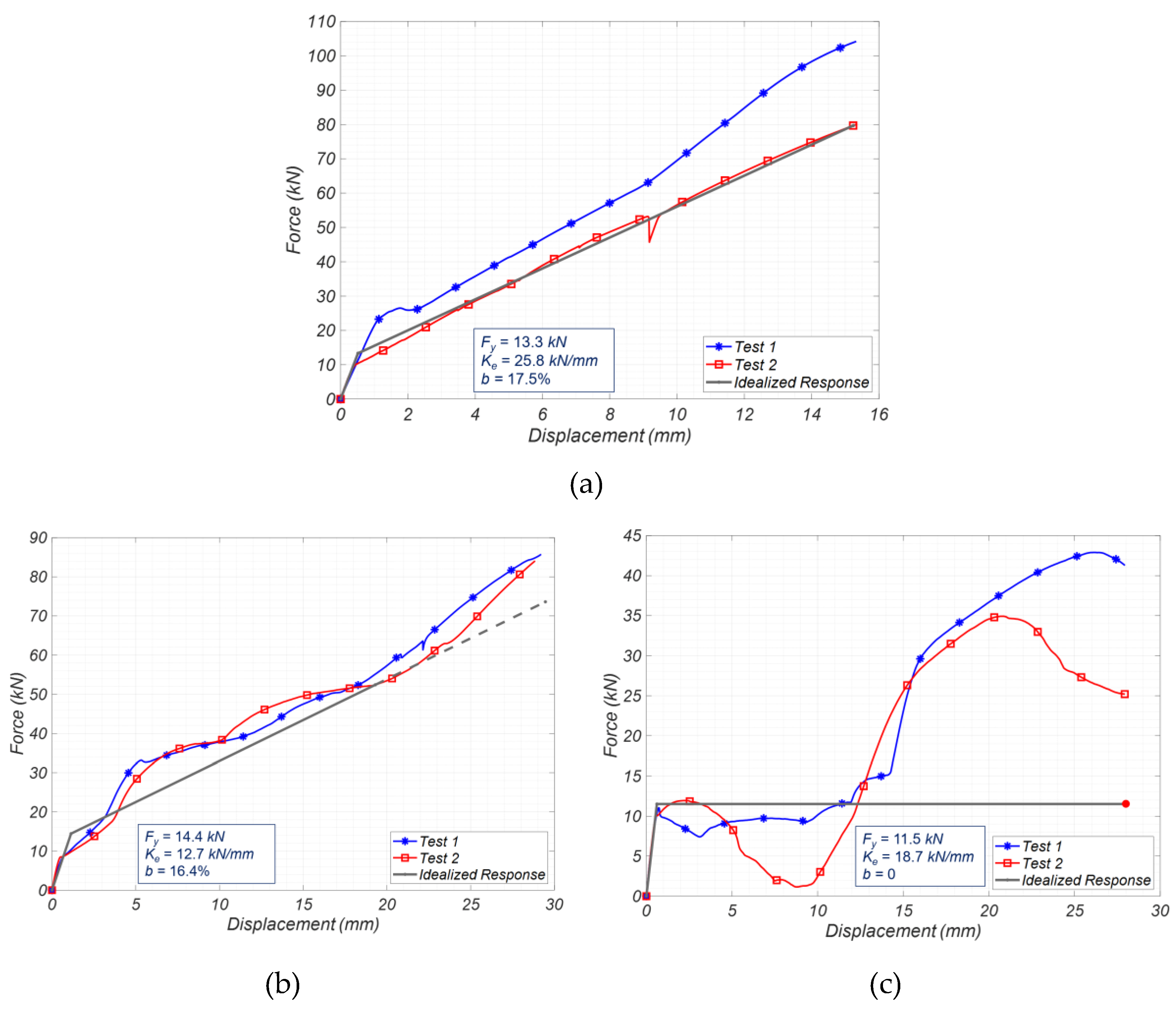
The force-deformation response of the Cage Clamp connection in the X-direction is shown in
Figure 5a. The results exhibit an initial linear response characterized by a stiffness of 25.8 kN/mm and a yield strength of approximately 13.3 kN. Subsequently, the plate yields in flexure, leading to a nonlinear force-deformation response. The dips observed in the force-deformation response of Test 2 around 9 mm are attributed to slippage that occurred at the grips of the Intron Machine and are unrelated to the behavior of the test specimen.
Similarly, the force-deformation responses in the Y-direction, as depicted in
Figure 5b, exhibit an initial linear response characterized by a stiffness of 12.7 kN/mm and a yield strength of approximately 14.4 kN. The nonlinearity observed in this direction is likely influenced by slip and interlock phenomena occurring between longitudinal and transverse rebar ribs, as well as between plates and transverse rebar ribs.
In Z-direction, the force-deformation responses are presented in
Figure 5c. Here, an initial linear behavior is observed, characterized by a stiffness of 18.7 kN/mm and a yield strength of approximately 11.5 kN. The initial linear stiffness is found to be about 48% greater than that of the stiffness observed in the Y-direction, while the yield strength is approximately 80% of the Y-directional value. The nonlinear response in the Z-direction is influenced by slip and interlock effects, contributing to the observed hardening behavior after approximately 10 mm deformation. It is important to note that the drop in the response of Test 2 at approximately 2.5 mm deformation is attributed to the slippage of the Cage Clamp on the longitudinal bars and the subsequent interlock with the ribs, which results in additional hardening behavior. Also, note that no failures were observed during any of the experiments, and the results are presented up to the maximum tested deformation, which is approximately 15 mm in the X-direction and around 28 mm in both the Y and Z-directions.
To incorporate experimental data into numerical models, bilinear models are employed to idealize the force-deformation responses. In order to idealize experimental force-deformation responses, the approach described in [
2] is used. By employing this process, the effective elastic stiffness (
Ke), the linear force limit (also referred to as the yield strength,
Fy), the post-yield stiffness ratio (
b), and post-yield stiffness (
Kb, defined as
Kb= b × Ke) are determined and specified in
Figure 5. The simplified curves are depicted in these figures using tick lines for visual representation. The values of
Ke,
Fy, and
b are also reported in
Table 1 for ease of access and comparison.
Figure 5.
Force-deformation response of Cage Clamp connection: (a) X-direction, (b) Y-direction, and (c) Z-direction.
Figure 5.
Force-deformation response of Cage Clamp connection: (a) X-direction, (b) Y-direction, and (c) Z-direction.
Table 1.
Summary of the proposed bilinear model parameters for Cage Clamp connections.
Table 1.
Summary of the proposed bilinear model parameters for Cage Clamp connections.
| DOF |
Ke (kN/mm) |
Fy (kN) |
b (%) |
Kb (kN/mm) |
| X |
25.8 |
13.3 |
17.5 |
4.52 |
| Y |
12.7 |
14.4 |
16.4 |
2.08 |
| Z |
18.7 |
11.5 |
0 |
0 |
2.3. Comparison of the Response of U-Bolt and Cage Clamp for Crossbar Connections
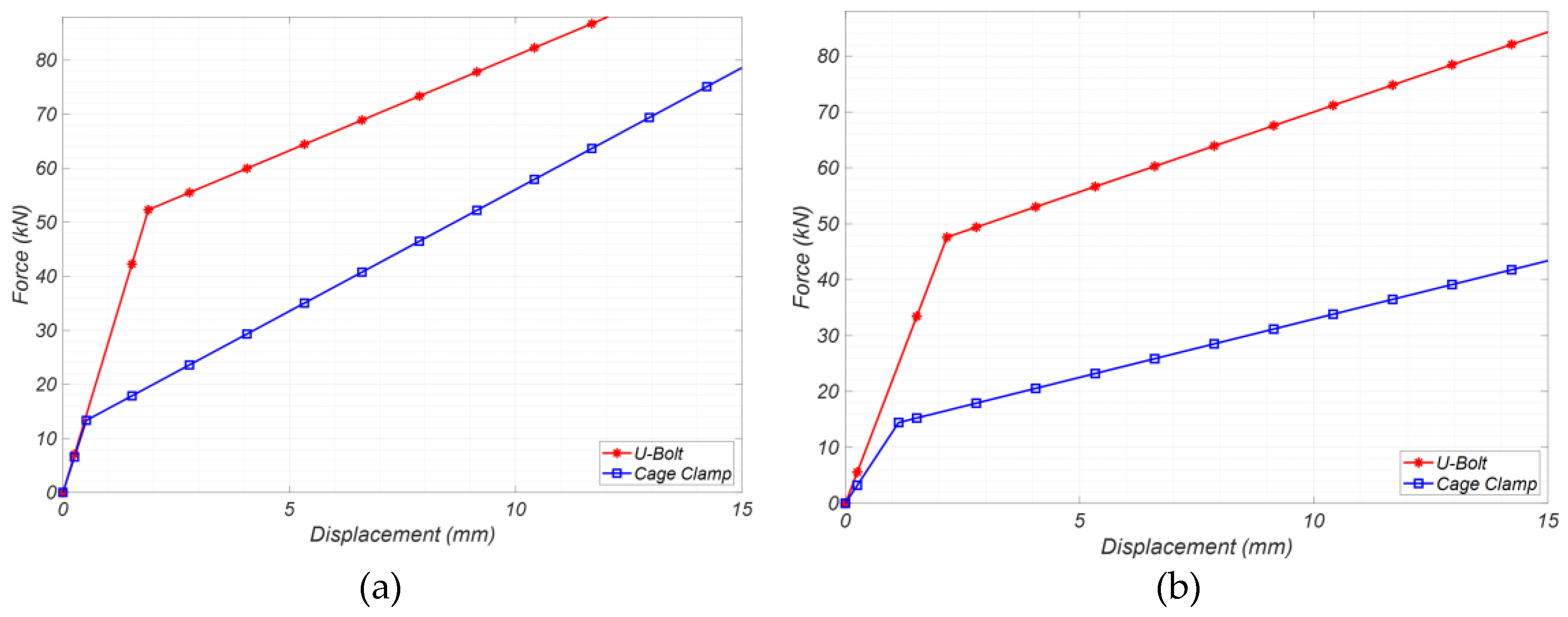
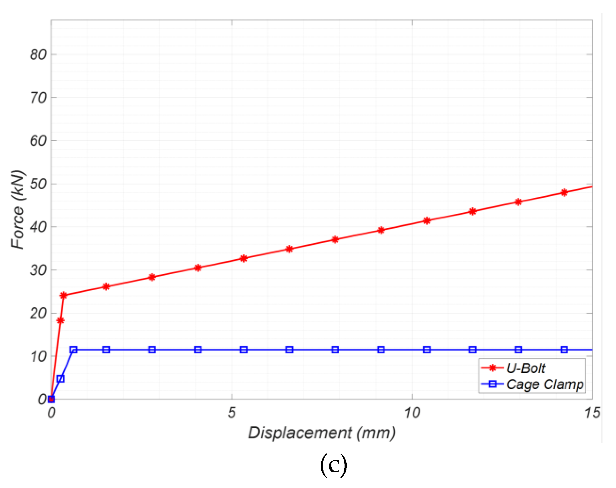
The behavior of U-bolt and Cage Clamp connections is compared by analyzing their idealized bilinear force-deformation responses in the X-direction, Y-direction, and Z-direction, as illustrated in
Figure 6. Cage Clamp connections exhibit remarkable strength and stiffness (as evident from
Table 1 and
Figure 5), surpassing tie-wire connections by orders of magnitude (as referenced in [
2] for tie-wire connection force-displacement response). However, compared to U-bolt connections, the Cage Clamp exhibits different behavior. This difference can be attributed to variations in the physical structure of the Cage Clamp and U-bolt connections. In U-bolt connections, longitudinal and transverse rebars interlock with a U-bolt and two plates, while in Cage Clamp connections, rebars are connected with a bent U-bolt and only one plate. In terms of effective elastic stiffness (
Ke), the U-bolt connection provides a stiffer connection than the Cage Clamp in all directions. The U-bolt connection is 8.5% stiffer in the X-direction, 73.2% stiffer in the Y-direction, and 385% stiffer in the Z-direction. Moreover, the yield strength (
Fy) of the U-bolt connection is higher than that of the Cage Clamp connection. In the X-direction, the U-bolt connection's yield strength is higher by about 4 times, in the Y-direction by about 3 times, and in the Z-direction by about 2 times. Although the strength and stiffness of Cage Clamp crossbar connections are less than U-bolt connections, they still provide enough stiffness and strength to ensure proper system-level behavior of rebar cages – as will be presented in the subsequent sections of this paper. As mentioned earlier, the Cage Clamps can provide a more attractive practical solution due to their lower cost of material and construction, and higher installation efficiency compared to U-bolts.
3. Full-Scale Experimental Tests
In this section, the results of full-scale experimental testing on an underground pile-shaft rebar cage with Cage Clamp connectors are presented. The objective is to investigate the behavior of a full-scale rebar cage reinforced with Cage Clamp connectors under common site handling conditions, such as lifting and tilting. Further details are provided in the subsequent sections.
3.1. Test Specimen and Material Properties
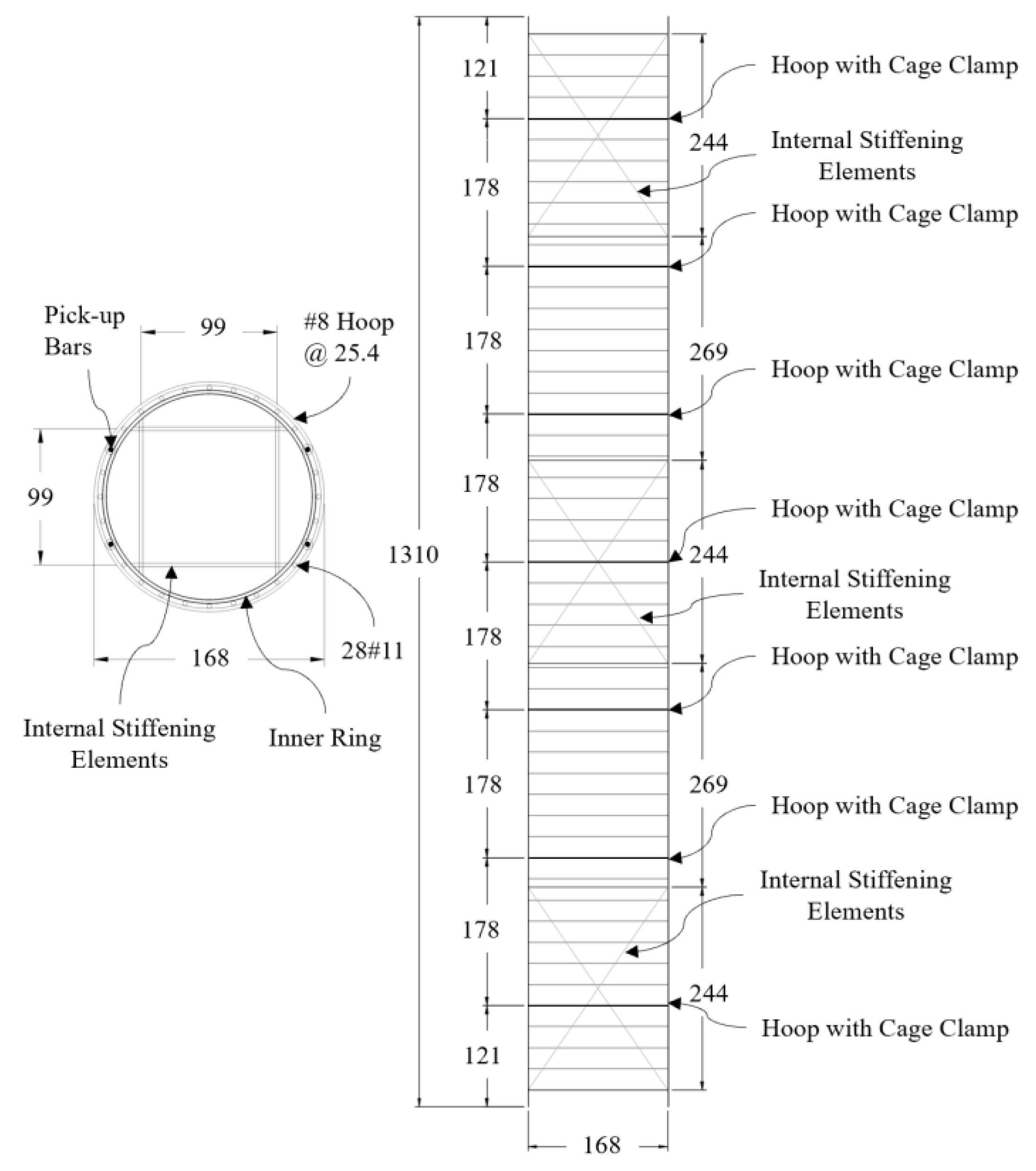
The test specimen used in this study was a circular rebar cage measuring 13.10 m in height and 1.68 m in outside diameter, with a weight of 41.31 kN, as demonstrated in
Figure 7. The longitudinal (
ρ) and transverse (
ρs) reinforcement ratios were 1.36% and 0.49%, respectively. The longitudinal rebars consisted of 28- #11 (equivalent to Φ36 metric) and #8 (equivalent to Φ25 metric) welded hoops, spaced at 25.4 cm intervals, serving as transverse reinforcement. The material used for the rebars was ASTM A706 Gr. 60.
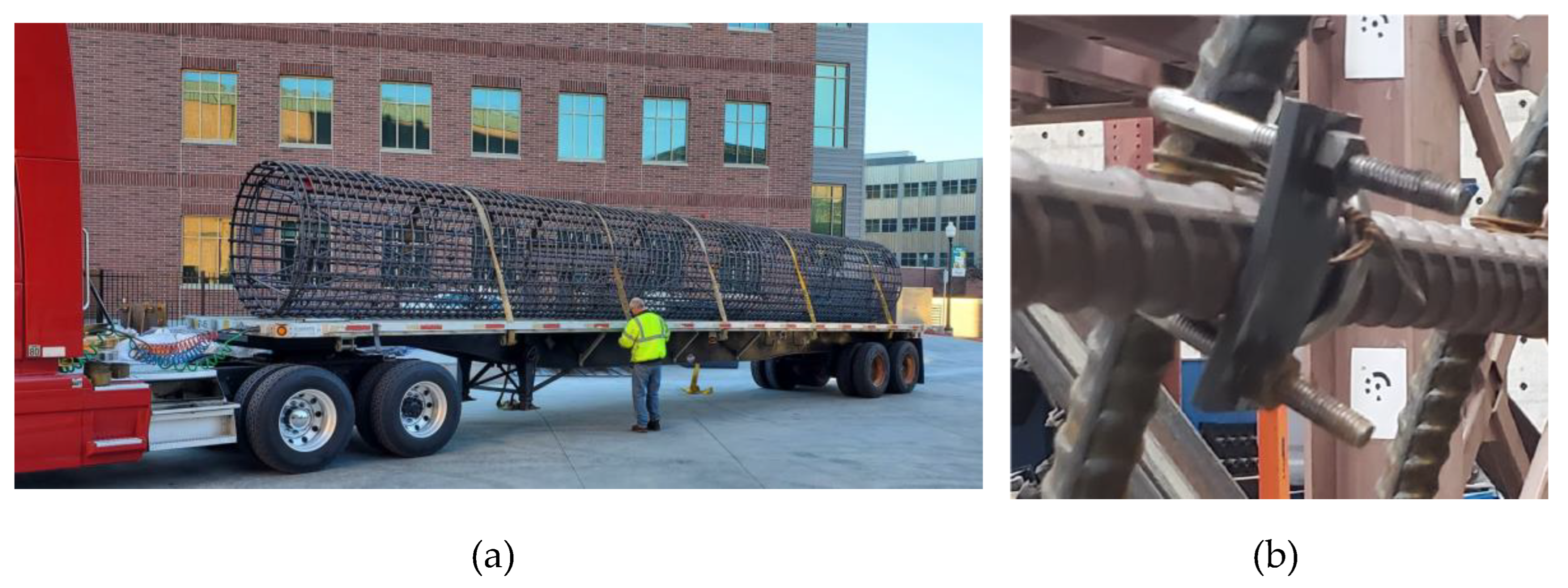
To ensure stability prior to testing, the test specimens were constructed and transported with internal stiffening elements (see
Figure 8a). Internal stiffening elements often need to be removed on site after the cage has been lifted to the vertical condition, prior to lowering into the ground to create clearance for the concrete placement and/or to meet seismic detailing requirements. In this project, internal stiffening elements were constructed using eight diagonal #8 rebars, welded to #8 hoops, referred to as inner rings. However, before testing, the internal stiffening elements were removed to study the behavior of rebar cages with Cage Clamp connectors in the absence of internal stiffening elements.
The Cage Clamp connectors were installed on seven selected hoops (template hoops), placed at 1.78 m intervals along the cages as shown in
Figure 7. On each template hoop, Cage Clamp connectors were installed at every other crossbar intersection. In total, 98 Cage Clamps (14 Cage Clamps per hoop × 7 hoops = 98) were installed on the test specimen. An impact wrench was used to tighten Cage Clamps, aiming for a proper and consistent tightening to achieve a tight-fit connection. To ensure this, the nuts were tightened until a small observable bending of approximately 5 degrees in the plates was achieved, as depicted in
Figure 8b. This visual bending was found to be equivalent to approximately 100 N.m of bolt torque.
Apart from the Cage Clamps, tie-wires were also utilized to connect the longitudinal and transverse rebars in the specimens. Tie-wires of low carbon soft-annealed No. 15 gauge steel wire, with a diameter of 1.83 mm and a minimum tensile strength of 276 MPa (40 ksi) were used. The pick-up bars (shown by dotted circles in
Figure 7) were tied to the transverse reinforcement with double-snap tie-wires at every crossbar intersection, except those connected by Cage Clamps. Additionally, the intersections of all inner rings with the longitudinal bars were tied with wrap-and-saddle double wire tie connections, following Caltrans guidelines [
6]. Other longitudinal and transverse rebar intersections along the length of the test specimens were tied at every third intersection with single-snap tie-wire connections. The total number of tie-wire and Cage Clamp connections is summarized in
Table 2.
Figure 7.
Details of the rebar cage test specimen (all dimensions are in cm).
Figure 7.
Details of the rebar cage test specimen (all dimensions are in cm).
Table 2.
The total number of tie-wire and Cage Clamp connectors in the test specimens. Refer to [
1] for details on different types of tie-wire connections.
Table 2.
The total number of tie-wire and Cage Clamp connectors in the test specimens. Refer to [
1] for details on different types of tie-wire connections.
| Connection type |
Number |
Percentage |
| Wrap-and-Saddle |
228 |
14.3% |
| Double-Snap |
274 |
17.2% |
| Single-Snap |
391 |
24.5% |
| No Connection |
605 |
37.9% |
| Cage Clamp Connector |
98 |
6.1% |
| Total |
1560 |
Figure 8.
(a) Transportation of the cage specimens prior to testing, (b) bending of the plates in a tight-fit connection.
Figure 8.
(a) Transportation of the cage specimens prior to testing, (b) bending of the plates in a tight-fit connection.
3.2. Test Setup and Loading Scenarios
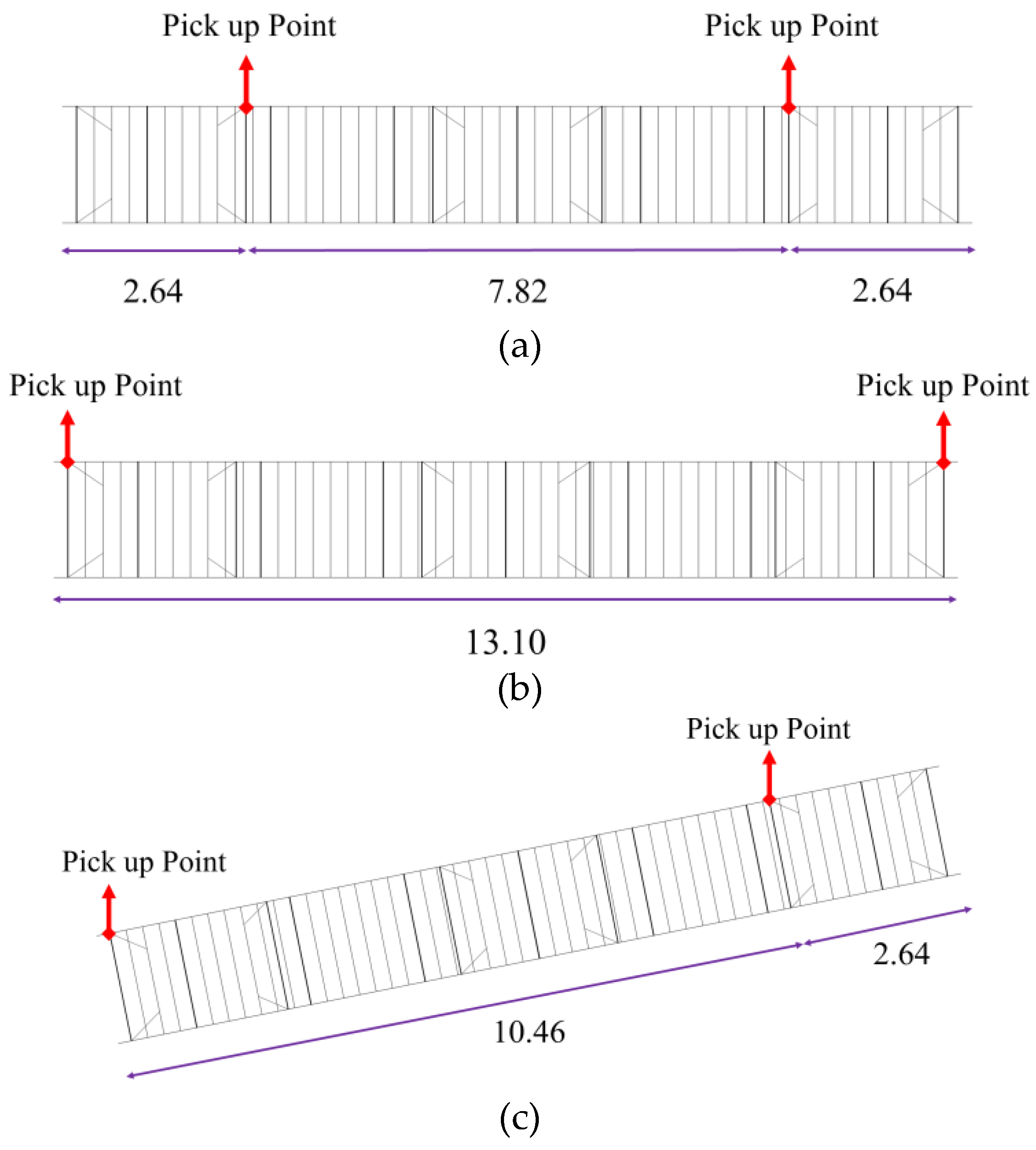
The specimen was tested under three different loading configurations, as depicted in
Figure 9. These configurations present the common site handling processes, including lifting and tilting. The experiments were conducted using two overhead cranes. The two top pick-up bars were lifted at each pick-up point by a lifting strap connected to the crane hook. The lifting process was slow and gradual to prevent any dynamic movements of the cage.
In the first test scenario, the pick-up points were positioned 2.64 m away from each end of the cage, equivalent to one-fifth of the cage's total length. This configuration represents the conventional method for lifting and handling rebar cages. In the second scenario, the rebar cage specimen was lifted from its far ends, a practice not commonly used but essential for validating numerical models. Finally, in the third scenario, one end of the cage was lifted, the other pick-up point was positioned 2.64 meters away from the opposite end, and the cage was tilted to an angle of approximately 40 degrees. This test aimed to evaluate the behavior of the cage during on-site tilting.
Figure 9.
Schematics of test scenarios: (a) Scenario 1, (b) Scenario 2, (c) Scenario 3 (dimensions are in m).
Figure 9.
Schematics of test scenarios: (a) Scenario 1, (b) Scenario 2, (c) Scenario 3 (dimensions are in m).
3.3. Target-Tracking DIC Measurement
The Digital Image Correlation (DIC) technique, utilizing the Trilion hardware-software system, was employed to capture the deflection profile of rebar cages and measure the deformation of test specimens. DIC is an optical non-contact method that tracks three-dimensional (3D) coordinates of target points in space. The technique is called 3D target-tracking DIC [
7], where targets are affixed to the test specimens to monitor deformation during experiments.
The DIC measurement process consisted of two phases: calibration and measurement. In the calibration phase, 2D images were transformed into a 3D cartesian coordinate space using photogrammetric methods [
8]. Triangulation technique was employed during the measurement phase to process the calibrated data and measure the movement of targets attached to the specimen [
9].
To perform DIC measurements, two high-speed cameras (IL5QM4, Fastec Imaging) were used [
10]. These cameras capture images with a resolution of 2560 × 2048 pixels in 8-bit grayscale. Two types of targets were tracked in the 3D target-tracking DIC: un-coded and coded targets. Un-coded targets acted as independent sensors and were rigidly attached to the specimen to reflect its deformation [
11]. Coded targets, on the other hand, were numbered with unique patterns for identification by the software.
During the calibration phase, the positions of the cameras and targets were determined using over 40 pictures taken from various perspectives. Distances between at least two coded targets were measured to define the "scale bars," thereby defining the dimensions of the point cloud. The TRITOP point tracking software was utilized to perform calibration calculations and determine point positions based on camera positions and image orientations. Readers are refer to [
4] for further details.
Once calibration was completed, the camera positions remained fixed throughout the testing. In the measurement phase, two sets of images were captured for each test scenario: one before the test to establish target positions on the undeformed specimen and one after the test to determine the displacement of targets in all three directions (X, Y, and Z) and measure the specimen's deformation.
3.4. Experimental Results and Observations
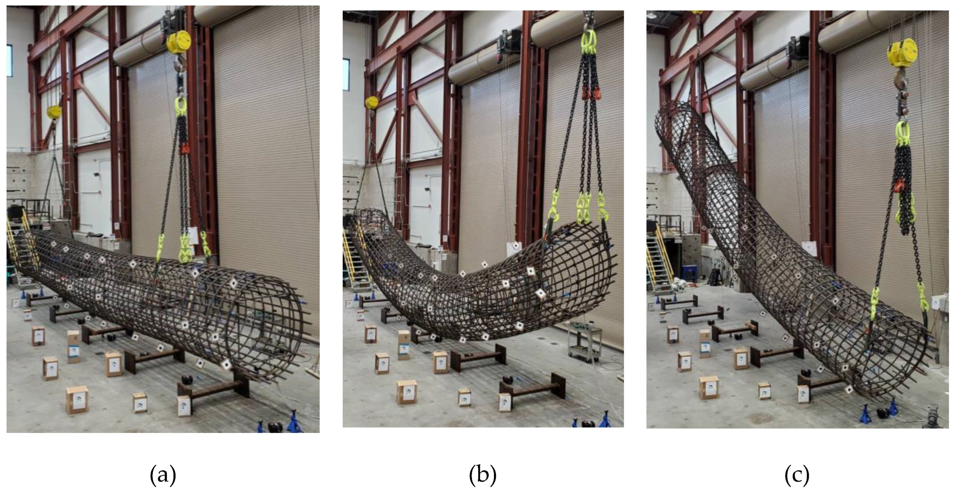
In this subsection, the test results of the full-scale experiments are presented. Test photos are shown in
Figure 10, and the cage deformation profiles are illustrated in
Figure 12, along with simulation results (to be discussed in the next section). The maximum measured deflection of the test specimen in each test scenario is listed in
Table 3.
In test scenario 1, representing the common lifting practice of rebar cages, the deflection was insignificant, amounting to 0.9% of the cage length. On the other hand, under extreme pick-up conditions (test scenario 2), where the cage was lifted from the two ends, the cage deflection was 12.8% of the cage length. Despite experiencing significant deformation (over 12% of the cage length), the specimens did not collapse, showcasing the effectiveness of Cage Clamps in maintaining the integrity of the cage. In contrast, a tie-wired cage without internal stiffening elements would have collapsed under similar loading conditions, as will be demonstrated in
Section 4.2. The results also indicate that the presence of Cage Clamp connectors allows the elimination of internal stiffening elements without compromising rebar cage safety. Moreover, it is observed that the selection of pick-up locations has an important impact on reducing deflection in the rebar cage. Comparing test scenarios 1 and 2, relocating the pick-up points from the two ends to locations approximately one-fifth of the cage length away from the ends resulted in 93% reduction in the specimen's deflection. Finally, in test scenario 3, the cage was picked up and tilted to about 40 degrees. It is worth noting that a considerable part of the specimen moved out of the DIC cameras' field of view in test scenario 3 (see
Figure 10c). Consequently, it was not possible to measure the deformation of the specimen completely. After completing each test scenario, the specimen was able to fully regain its initial shape without any permanent distortion or deformation. No failure or damage occurred in any of the tests, nor was any slippage observed in the Cage Clamps.
Figure 10.
Deformed shape of the specimen during different test scenarios: (a) scenario 1, (b) scenario 2, (c) scenario 3.
Figure 10.
Deformed shape of the specimen during different test scenarios: (a) scenario 1, (b) scenario 2, (c) scenario 3.
Table 3.
Maximum measured deflection.
Table 3.
Maximum measured deflection.
| Test scenario |
Maximum measured deflection |
| Value (mm) |
% of cage length |
| 1 |
116 |
0.9% |
| 2 |
1677 |
12.8% |
4. Finite Element Simulation and Analysis
4.1. Finite Element Modeling
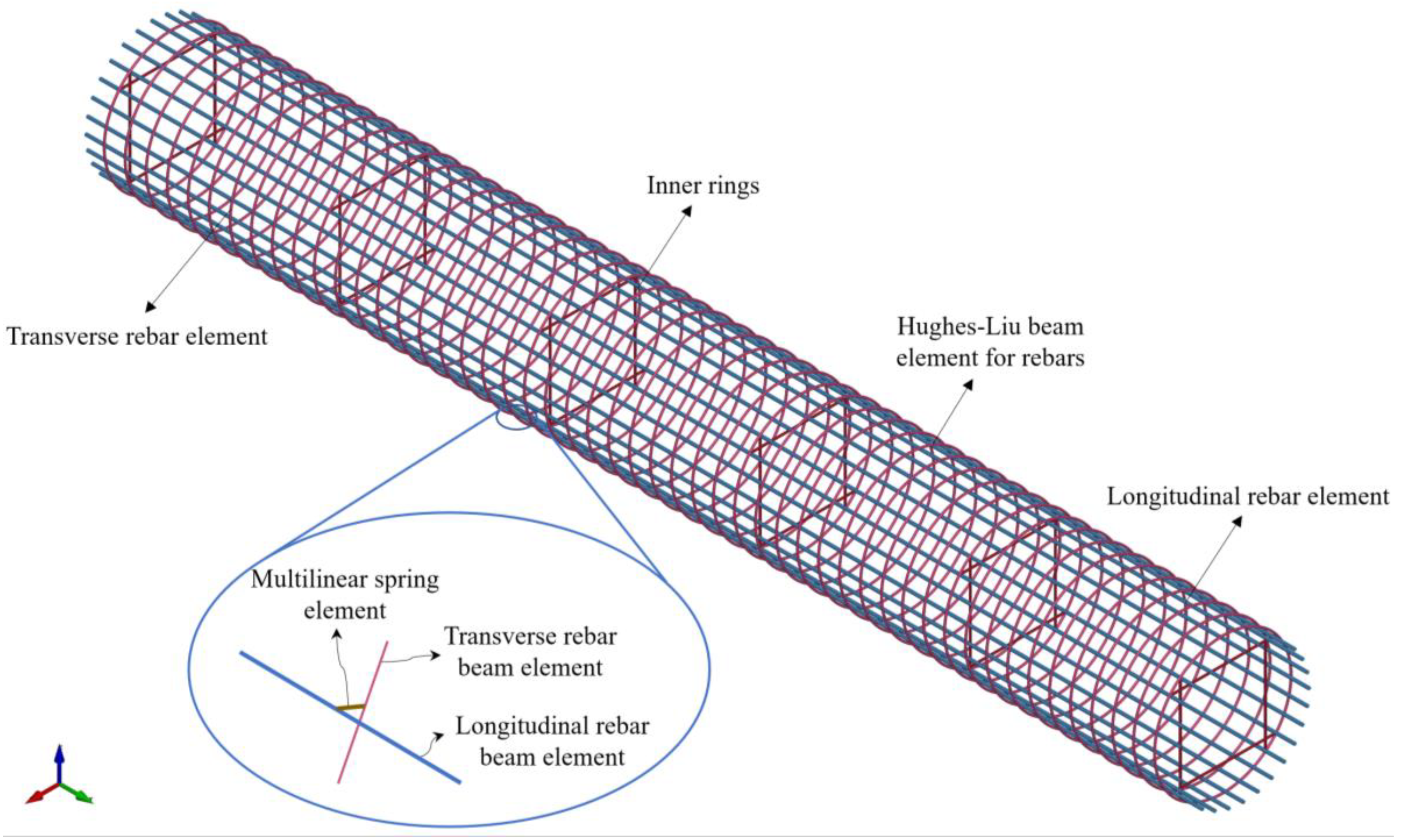
This section presents detailed finite element (FE) models utilized to analyze the test specimen, along with the simulation results and their comparison with experimental measurements. The FE models are developed using the LS-DYNA FE simulation platform [
12]. The geometry of the rebar cage specimen, including the details of reinforcing bars, tie-wire distribution, and Cage Clamp connections, are precisely defined based on the as-built details (see
Figure 11). The reinforcing bars are modeled using Hughes-Liu beam elements with fiber sections. An elastic-perfectly-plastic material model with a yield strength
MPa and Young’s modulus
Gpa is applied to represent the behavior of the rebars. To account for the mass of steel rebars, a material density of 7850 kg/m
3 is assigned to all longitudinal and transverse rebars. The boundary conditions at the pick-up points are defined as hinge supports. To replicate the quasi-static loading conditions of the tests, gravity load is applied incrementally over a period of 10 seconds. Additionally, to damp the dynamic response of the model, a Rayleigh damping model with a 15% damping ratio anchored at two distant frequencies (
f1 = 0.1 Hz,
f2 = 100 Hz) is implemented to dissipate dynamic responses across a wide frequency range. The connections between rebar intersections are modeled using multilinear discrete spring elements uncoupled in six degrees of freedom (DOFs), including three translational (
X,
Y, and
Z) and three rotational (
Rx,
Ry, and
Rz) DOFs. The force-displacement responses for the tie-wire connections are based on the responses proposed in [
1]. For the Cage Clamp connections, the translational DOFs are modeled using an idealized bilinear model presented in
Figure 5. The numerical simulation utilizes an explicit solver with a central difference algorithm. A time step
sec is chosen to solve the equilibrium equation in time.
The initial sensitivity analysis indicated that the rotational stiffness of Cage Clamp connections in the
Rx direction (i.e.,
) significantly impacts the behavior of the rebar cage model [
4], while the stiffness in the
Ry and
Rz directions has a negligible effect (see
Figure 2). To accurately estimate the rotational stiffness (
) in the
Rx direction, an optimization-based model updating process as described in [
4], is employed. In this method, the objective function quantifies the differences between measured and model-predicted deformations based on the loading scenario of test scenario 2. The optimization iteratively adjusts
until the objective function change is below a tolerance criterion, resulting in an estimated value of
N.m/rad.
Using the developed FE model, the simulated cage displacement profiles are compared with the experimental measurements for test scenarios 1 and 2. The numerical models replicate the deflection behavior of the rebar cage reinforced with both tie-wires and Cage Clamp connections with acceptable accuracy.
Figure 12.
Comparison between the experimentally measured and numerically simulated displacement profiles of the specimen: (a) scenario 1, (b) scenario 2.
Figure 12.
Comparison between the experimentally measured and numerically simulated displacement profiles of the specimen: (a) scenario 1, (b) scenario 2.
4.2. Cage Deflection Sensitivity with Respect to the Number of Cage Clamps
The numerical models indicate that in the extreme loading scenario, where the cage is lifted from both ends, the maximum internal loads in the Cage Clamps do not exceed 10% of the linear force limit (or yield strength, Fy). Furthermore, as previously mentioned, no slippage or damage occurred in any of the Cage Clamps during the experiments. This observation suggests that only a portion of the Cage Clamps' capacity was utilized in the experimental loading scenario. Consequently, it can be inferred that the number of Cage Clamps can be reduced without having a risk of failure in the rebar cage.
To assess the effect of the number of Cage Clamps on the deflection of the rebar cage, numerical sensitivity analyses are conducted. The numerical models are developed to be identical to those described in the previous section, with the same geometry and properties, except for the number of Cage Clamps. In these models, Cage Clamp connectors are installed on six hoops, spaced at 2.54 m intervals along the cage length. The number of Cage Clamps per hoops varied in five developed models: 14, 8, 6, 4, and 0. Hence, the total number of Cage Clamps in those models is 84, 48, 36, 24, and 0, respectively. These rebar cage models lacked internal stiffening elements, with their rebars connected solely by tie wires and Cage Clamps. Notably, the 5th model does not incorporate any Cage Clamps; instead, the longitudinal and transverse rebars are connected exclusively by tie wires.
The models are lifted from the two ends, similar to Scenario 2, by defining simple supports at the pick-up bars and applying gravity incrementally. Table 10 lists each model's maximum deflection and internal loads in the Cage Clamps. The cage models remained undamaged even after experiencing significant deflection for the first four models, and the internal load in Cage Clamps remained well within the linear limit under gravity load. These results demonstrate that, in the absence of internal stiffening elements, using only 4 Cage Clamps (placed solely on pick-up bars) at 2.54 m intervals provides sufficient strength for the rebar cage to remain stable during lifting loading conditions.
Conversely, the cage model failed under its weight in the fifth model (i.e., tied-wire rebar cage model with no Cage Clamps). These results highlight that a rebar cage without mechanical connectors and internal stiffening elements is susceptible to failure during the lifting process.
Table 4.
Maximum Deflection and internal forces in Cage Clamp connectors in the numerical models. The local force directions for Cage Clamps are based on
Table 1.
Table 4.
Maximum Deflection and internal forces in Cage Clamp connectors in the numerical models. The local force directions for Cage Clamps are based on
Table 1.
| |
# of Cage Clamps
(# of Cage Clamps per hoop × # of hoops) |
Max Deflection
(mm) |
|
| X-direction |
Y-direction |
Z-direction |
| Model 1 |
14×6 = 84 |
1617 |
3.6% |
4.6% |
4.3% |
| Model 2 |
8×6 = 48 |
1785 |
3.7% |
6.1% |
7.7% |
| Model 3 |
6×6 = 36 |
1806 |
3.7% |
6.4% |
8.2% |
| Model 4 |
4×6 = 24 |
1818 |
3.5% |
4.3% |
5.5% |
| Model 5 |
0 |
Failed Under Gravity Load |
- |
- |
- |
5. Conclusions
This paper presented a comprehensive experimental and numerical investigation of Cage Clamp connectors for their application in prefabricated rebar cages. The research had multiple objectives. The first objective was to obtain the force-displacement response of Cage Clamps for crossbar connections. To achieve this goal, component-level experimental tests were conducted to determine the mechanical properties and force-deformation responses of Cage Clamps for crossbar connection in different degrees of freedom (DOFs). Subsequently, the force-deformation responses were simplified using bilinear models, enabling application in numerical simulations to study the system-level behavior of rebar cages with Cage Clamp connectors. The results revealed that Cage Clamp connectors exhibit remarkable strength and stiffness, surpassing traditional tie-wire connections by orders of magnitude. The second objective of this research was to investigate the behavior of rebar cages reinforced with Cage Clamp connectors under various site handling conditions. To this end, full-scale experimental tests were performed on a circular rebar cage with Cage Clamp connectors under lifting and tilting loading scenarios. The results demonstrated the capability of Cage Clamp connectors to maintain the integrity of the rebar cage without internal stiffening elements. Notably, it was shown that the presence of Cage Clamp connectors allowed for the elimination of internal stiffening elements, simplifying the construction process. This is important since tie-wired rebar cages (without internal stiffening elements) are prone to failure under gravity loads. Furthermore, finite element (FE) numerical models were developed and calibrated using experimental data to predict the behavior of rebar cages with Cage Clamp connectors. The simulations exhibited a close match with the experimental results, thereby validating the accuracy and reliability of the FE models. These simulations successfully captured the deflection profile of rebar cages with Cage Clamp connectors and tie-wires. In addition, numerical sensitivity analyses were performed to assess the performance of the rebar cage with a reduced number of cage clamps. The key observation was that using Cage Clamps to connect pick-up bars to the transverse reinforcement at intervals of 8 to 10 feet is adequate to maintain the stability of the rebar cage studied here during typical site handling conditions without compromising the safety of the specimen.
The results of this experimental and numerical study have important implications for the design and construction of rebar cages. The application of Cage Clamp mechanical connectors offers a reliable and efficient solution to enhance the stability and safety of these temporary structures. Further investigations are underway to develop practical analysis, design, fabrication, and handling guidelines for rebar cages with different types of mechanical connectors, including Cage Clamps.
Declaration of Competing Interest
The authors declare that they have no known competing financial interests or personal relationships that could have appeared to influence the work reported in this paper.
Acknowledgments
This paper is the result of a research project funded through ASCE Construction Institute with contributions received from Charles Pankow Foundation, and several industry partners. The authors would like to extend their sincere appreciation to members of the industry steering committee: Angie Hunter, Anne Ellis, Brett Lord, Brian Ruegge, Jeff Veilleux, Justin Ramer, Katerina Lachinova, Lyle Sieg, Mark Bennier, Mark Perniconi, Peter Speier, Ray Fassett, Stuart Harrison, and Tanner Blackburn, for their invaluable contributions and unwavering support throughout the research project. The authors are thankful to the Earthquake Engineering Lab staff at the University of Nevada, Reno, Dr. Patrick Laplace, Mr. Todd Lyttle, and Mr. Chad Lyttle for their dedicated assistance during the experimental testing. The authors would also like to especially acknowledge Mr. Vince Siefert, the chair of the project’s steering committee, for his support and contribution to this research project.
References
- J. C. Builes-Mejia, A. Itani, and H. Sedarat, Stability of bridge column rebar cages during construction. University of Nevada, Reno, 2010.
- M. Vahedi, H. Ebrahimian, and A. M. Itani, “Experimental Investigation of U-Bolt Connectors for Application in Rebar Cages,” Journal of Structural Engineering, vol. 149, no. 1, p. 4022216, 2023. [CrossRef]
- M. Vahedi, H. Ebrahimian, and A. M. Itani, CCEER-22-02: Response And Behavior Of Mechanical Connectors For Application In Rebar Cages: An Experimental Study. University of Nevada, Reno, 2022.
- M. Vahedi, H. Ebrahimian, and A. M. Itani, “Full-Scale Testing and Analytical Modeling of Rebar Cages Reinforced with Mechanical U-Bolt Connectors,” Applied Sciences, vol. 13, no. 14, p. 8113, Jul. 2023. [CrossRef]
- M. Vahedi, H. Ebrahimian, and A. M. Itani, “Experimental Study of Mechanical Connectors for Application in Rebar Cages,” in Construction Research Congress 2022, 2022, pp. 171–177. [CrossRef]
- Caltrans, Standard Specifications. Sacramento, CA, USA.: California Department of Transportation, 2022.
- L. Ngeljaratan and M. A. Moustafa, “Structural health monitoring and seismic response assessment of bridge structures using target-tracking digital image correlation,” Engineering Structures, vol. 213, p. 110551, 2020.
- GOM Precise Industrial 3D Metrology, “TRITOP Professional.” Optical 3D Coordinate Measuring Machine, 2017.
- GOM Precise Industrial 3D Metrology, “GOM Correlate Professional.” GOM Correlate-Evaluation Software for 3D Testing, 2017.
- FASTEC, “FasMotion.” Fastec Imaging Inc, 2021.
- R. Hartley and A. Zisserman, Multiple view geometry in computer vision. Cambridge University Press, 2003.
- LSTC LS-DYNA, “Keyword User’s Manual,” Livermore: Livermore Software Technology Corporation (LSTC), 2017.
|
Disclaimer/Publisher’s Note: The statements, opinions and data contained in all publications are solely those of the individual author(s) and contributor(s) and not of MDPI and/or the editor(s). MDPI and/or the editor(s) disclaim responsibility for any injury to people or property resulting from any ideas, methods, instructions or products referred to in the content. |
© 2024 by the authors. Licensee MDPI, Basel, Switzerland. This article is an open access article distributed under the terms and conditions of the Creative Commons Attribution (CC BY) license (http://creativecommons.org/licenses/by/4.0/).
