Submitted:
20 February 2024
Posted:
21 February 2024
You are already at the latest version
Abstract
Keywords:
1. Introduction
2. LNA Schematic and Device Modeling
3. Experimental Results
3.1. Test Setup for Performance Measurement
3.2. Performance Degradations and Modeling
4. Analysis and Discussion
5. Summary
Author Contributions
Funding
Data Availability Statement
Conflicts of Interest
References
- Cressler, J.D. SiGe HBT Technology: A New Contender for Si-Based RF and Microwave Circuit Applications. IEEE Transactions on Microwave Theory and Techniques, 1998, vol. 46, pp. 572-589.
- Song, I.; Cardoso, A. S.; Ying, H.; Cho, M. -K.; Cressler, J. D. Cryogenic Characterization of RF Low-Noise Amplifiers Utilizing Inverse-Mode SiGe HBTs for Extreme Environment Applications. IEEE Transactions on Device and Materials Reliability, 2018, vol. 18, pp. 613-619.
- Cressler, J. D. On the Potential of SiGe HBTs for Extreme Environment Electronics. In Proceedings of the IEEE, 2005, vol. 93, pp. 1559-1582.
- 4. Zhuoqi Li.; Shuhuan Liu.; Xiaotang Ren.; Mathew Adefusika Adekoya.; Jun Zhang.; Shuangying Liu. Experimental Investigation on the Degradation of SiGe LNAs under Different Bias Conditions Induced by 3 MeV Proton Irradiation. Nuclear Engineering and Technology, 2022, vol. 54, pp. 661-665.
- 5. Song, I.; Jung, S.; Lourenco, N. E.; Raghunathan, U. S.; Fleetwood, Z. E.; Zeinolabedinzadeh, S.; Gebremariam, T. B.; Inanlou, F.; Roche, N. J.-H.; Khachatrian, A.; McMorrow, D.; Buchner, S. P.; Melinger, J. S.; Warner, J. H.; Paki-Amouzou, P.; Cressler, J. D. Design of Radiation-Hardened RF Low-Noise Amplifiers Using Inverse-Mode SiGe HBTs. IEEE Transactions on Nuclear Science, 2014, vol. 61, pp. 3218-3225.
- 6. Teng, J. W.; Ildefonso, A.; Tzintzarov, G. N.; Ying, H.; Moradinia, A.; Wang, P. F.; Li, Xun.; Zhang, E. X.; Fleetwood, D. M.; Cressler, J. D. Variability in Total-Ionizing-Dose Response of Fourth-Generation SiGe HBTs. IEEE Transactions on Nuclear Science, 2021, vol. 68, pp. 949-957.
- 7. Cressler, J. D. Radiation Effects in SiGe Technology. IEEE Transactions on Nuclear Science, 2013, vol. 60, pp. 1992-2014. [CrossRef]
- Nergui, D.; Teng, J. W.; Hosseinzadeh, M.; Mensah, Y.; Li, K.; Gorchichko, M.; Ildefonso, A.; Ringel, B. L.; Zhang, E. X.; Fleetwood, D. M.; Cressler, J. D. Total-Ionizing-Dose Response of SiGe HBTs at Elevated Temperatures. IEEE Transactions on Nuclear Science, 2022, vol. 69, pp. 1079-1084.
- Wachter, M. T.; Ildefonso, A.; Fleetwood, Z. E.; Lourenco, N. E.; Tzintzarov, G.; McMorrow, D.; Roche, N. J.-H.; Khachatrian, A.; McMarr, P.; Hughes, H.; Warner, J. H.; Paki, P.; Cressler, J. D. The effects of total ionizing dose on the transient response of SiGe BiCMOS technologies. In 2016 16th European Conference on Radiation and Its Effects on Components and Systems (RADECS), Bremen, Germany, 2016, pp. 1-5. [CrossRef]
- Wang, X.; Li, X.; Zhang, J.; Heini, M.; Liu, M.; Liu, H. Effects of Total Ionizing Dose on Low Frequency Noise Characteristics in SiGe HBT. In 2023 5th International Conference on Radiation Effects of Electronic Devices (ICREED). Kunming, China, 2023, pp. 1-5. [CrossRef]
- 11. Davulcu, M.; Çalışkan, C.; Kalyoncu, İ.; Gurbuz, Y. An X-Band SiGe BiCMOS Triple-Cascode LNA With Boosted Gain and P1dB. IEEE Transactions on Circuits and Systems II: Express Briefs, 2018, vol. 65, pp. 994-998. [CrossRef]
- Song, I.; Cho, M. K.; Oakley, M. A.; Ildefonso, A.; Ju, I.; Buchner, S. P.; McMorrow, D.; Paki, P.; Cressler, J. D. On the Application of Inverse-Mode SiGe HBTs in RF Receivers for the Mitigation of Single-Event Transients. IEEE Transactions on Nuclear Science, 2017, vol. 64, pp. 1142-1150. [CrossRef]
- Zhuoqi Li.; Shuhuan Liu.; Mathew Adefusika Adekoya.; Xiaotang Ren.; Jun Zhang.; Shuangying Liu.; Long Li. Radiation response of SiGe low noise amplifier irradiated with different energy protons. Microelectronics Reliability, 2021, vol. 127, ISSN 0026-2714.
- Sarker, M.A.R.; Jung, S.; Ildefonso, A.; Khachatrian, A.; Buchner, S.P.; McMorrow, D.; Paki, P.; Cressler, J.D.; Song, I. Mitigation of Single-Event Effects in SiGe-HBT Current-Mode Logic Circuits. Sensors 2020, 20, 2581. [CrossRef] [PubMed]
- Zhang, J.; Guo, Q.; Guo, H.; Lu, W.; He, C.; Wang, X.; Li, P.; Liu, M. Impact of Bias Conditions on Total Ionizing Dose Effects of 60Coγ in SiGe HBT. IEEE Transactions on Nuclear Science, 2016, vol. 63, pp. 1251-1258. [CrossRef]
- Kobal, E. Siriburanon, T.; Staszewski. R. B.; Zhu, A. A Compact, Low-Power, Low-NF, Millimeter-Wave Cascode LNA With Magnetic Coupling Feedback in 22-nm FD-SOI CMOS for 5G Applications. IEEE Transactions on Circuits and Systems II: Express Briefs, 2023, vol. 70, pp. 1331-1335. [CrossRef]
- Jia, X.; Niu, G. Impact of Correlated RF Noise on SiGe HBT Noise Parameters and LNA Design Implications. IEEE Transactions on Electron Devices, 2014, vol. 61, pp. 2324-2331. [CrossRef]
- Song, I.; Ryu, G.; Jung, S.H.; Cressler, J.D.; Cho, M.-K. Wideband SiGe-HBT Low-Noise Amplifier with Resistive Feedback and Shunt Peaking. Sensors 2023, 23, 6745. [Google Scholar] [CrossRef] [PubMed]
- Lee, Seonghearn.; Ryum, B. R.; Kang, S. W. A New Parameter Extraction Technique for Small-Signal Equivalent Circuit of Polysilicon Emitter Bipolar Transistors. IEEE Transactions on Electron Devices. 1994, vol. 41, pp. 233-238. [CrossRef]
- Sarker, M.A.R.; Song, I. Design and Analysis of fT-Doubler-Based RF Amplifiers in SiGe HBT Technology. Electronics 2020, 9, 772. [Google Scholar] [CrossRef]
- Lee, K.; Choi, K.; Kook, S. H.; Cho, D. H.; Park, K. W.; Kim, B. Direct Parameter Extraction of SiGe HBTs for the VBIC Bipolar Compact Model. IEEE Transactions on Electron Devices, 2005, vol. 52, pp. 375-384. [CrossRef]
- 22. SiGe Power Amplifier Platforms. gf.com/wp-content/uploads/2021/12/GF21-SiGe-PA-0705.pdf (16, 2, 2024).
- Sirohi, S.; Sirohi, S.; Jain, V.; Raman, A.; Nukala, B.; Veeramani, E.; Adkisson, J. W.; Joseph, A. Impact of Emitter Width Scaling on Performance and Ruggedness of SiGe HBTs for PA Applications. In 2018 IEEE BiCMOS and Compound Semiconductor Integrated Circuits and Technology Symposium (BCICTS), San Diego, CA, USA, 2018, pp. 182-185. [CrossRef]
- Song, I.; Cho, M; K.; Lourenco, N. E.; Fleetwood, Z. E.; Jung, S.; Roche, N. J.-H.; Khachatrian, A.; Buchner, S. P.; McMorrow, D.; Paki, P.; Cressler, J. D. The Use of Inverse-Mode SiGe HBTs as Active Gain Stages in Low-Noise Amplifiers for the Mitigation of Single-Event Transients. IEEE Transactions on Nuclear Science, 2017, vol. 64, pp. 359-366. [CrossRef]
- Gorchichko, M.; Cao, Y.; Zhang, E. X.; Yan, D.; Gong, H.; Zhao, S. E.; Wang, P.; Jiang, R.; Liang, C.; Fleetwood, D. M.; Schrimpf, R. D.; Reed, R. A.; Linten, D. Total-Ionizing-Dose Effects and Low-Frequency Noise in 30-nm Gate-Length Bulk and SOI FinFETs With SiO2/HfO2 Gate Dielectrics. IEEE Transactions on Nuclear Science, 2020, vol. 67, pp. 245-252. [CrossRef]
- Lambert, D.; Gaillardin, M.; Raine, M.; Paillet, P.; Duhamel, O.; Marcandella, C.; Martinez, M.; Rostand, N.; Lagutère, T.; Aubert, D.; Assaillit, G.; Delbos, C. TID Effects Induced by ARACOR, 60Co, and ORIATRON Photon Sources in MOS Devices: Impact of Geometry and Materials. IEEE Transactions on Nuclear Science, 2021, vol. 68, pp. 991-1001. [CrossRef]
- Gaillardin, M.; Lambert, D.; Aubert, D.; Raine, M.; Marcandella, C.; Assaillit, G.; Auriel, G.; Martinez, M.; Duhamel, O.; Ribière, M.; Rostand, N.; Lagutère, T.; Paillet, P.; Delbos, C.; Poujols, D.; Ritter, S. Investigations on Spectral Photon Radiation Sources to Perform TID Experiments in Micro- and Nano-Electronic Devices. IEEE Transactions on Nuclear Science, 2021, vol. 68, pp. 928-936. [CrossRef]
- Shiming Zhang.; Cressler, J. D.; Guofu Niu.; J, C.; Marshall.; W, P.; Marshall.; Kim, H.S.; Reed, Robert A.; Palmer, M. J.; Joseph, Alvin J.; Harame, D. L. The effects of operating bias conditions on the proton tolerance of SiGe HBTs. Solid-State Electronics, 2003, vol. 47, pp. 1729-1734.
- Yabin Sun.; Ziyu Liu.; Jun Fu.; Xiaojin Li.; Yanling Shi. Investigation of total dose effects in SiGe HBTs under different exposure conditions. Radiation Physics and Chemistry, 2018, vol. 151, pp. 84-89.
- Habeenzu, B. Effect of electron radiation on small-signal parameters of NMOS devices at mm-wave frequencies. Microelectronics Reliability, 2020, vol. 107, ISSN 0026-2714. (www.sciencedirect.com/science/article/pii/S0026271419306699).
- Prakash, A.P.G.; Pradeep. T.M.; Hegde, V.N.; Pushpa, N.; Bajpai, P.K.; Patel, S.P.; Trivedi, T.; Bhushan. K.G. Comparison of effect of 5 MeV proton and Co-60 gamma irradiation on silicon NPN rf power transistors and N–channel depletion MOSFETs. Radiat. Eff. Defect Solid, 2017, vol. 172, pp. 952-963. [CrossRef]
- 32. Wei-Min Lance Kuo.; Yuan Lu.; Floyd, B.A.; Haugerud, B.M.; Sutton, A.K.; Krithivasan, R.; Cressler, J.D.; Gaucher, B.P.; Marshall, P.W.; Reed, R.A.; Freeman, G. Proton radiation response of monolithic Millimeter-wave transceiver building blocks implemented in 200 GHz SiGe technology. IEEE Transactions on Nuclear Science, 2004, vol. 51, pp. 3781-3787. [CrossRef]
- Yuan Lu.; Cressler, J.D.; Krithivasan, R.; Ying Li.; Reed, R.A.; Marshall, P.W.; Polar, C.; Freeman, G.; Ahlgren, D. Proton tolerance of third-generation. 0.12 /spl mu/m 185 GHz SiGe HBTs. IEEE Transactions on Nuclear Science, 2003, vol. 50, pp. 1811-1815. [CrossRef]
- Shiming Zhang.; Guofu Niu.; J. D. Cressler.; S. D. Clark and D. C. Ahlgren. The effects of proton irradiation on the RF performance of SiGe HBTs. IEEE Transactions on Nuclear Science, 1999, vol. 46, pp. 1716-1721. [CrossRef]
- Jia, X.; Niu, G. Impact of Correlated RF Noise on SiGe HBT Noise Parameters and LNA Design Implications. IEEE Transactions on Electron Devices, 2014, vol. 61, pp. 2324-2331. [CrossRef]
- Nergui, D.; Teng, J. W.; Hosseinzadeh, M.; Mensah, Y.; Li, K.; Gorchichko, M.; Ildefonso, A.; Ringel, B. L.; Zhang, E. X.; Fleetwood, D. M.; Cressler, J. D. "Total-Ionizing-Dose Response of SiGe HBTs at Elevated Temperatures. IEEE Transactions on Nuclear Science, 2022, vol. 69, pp. 1079-1084. [CrossRef]
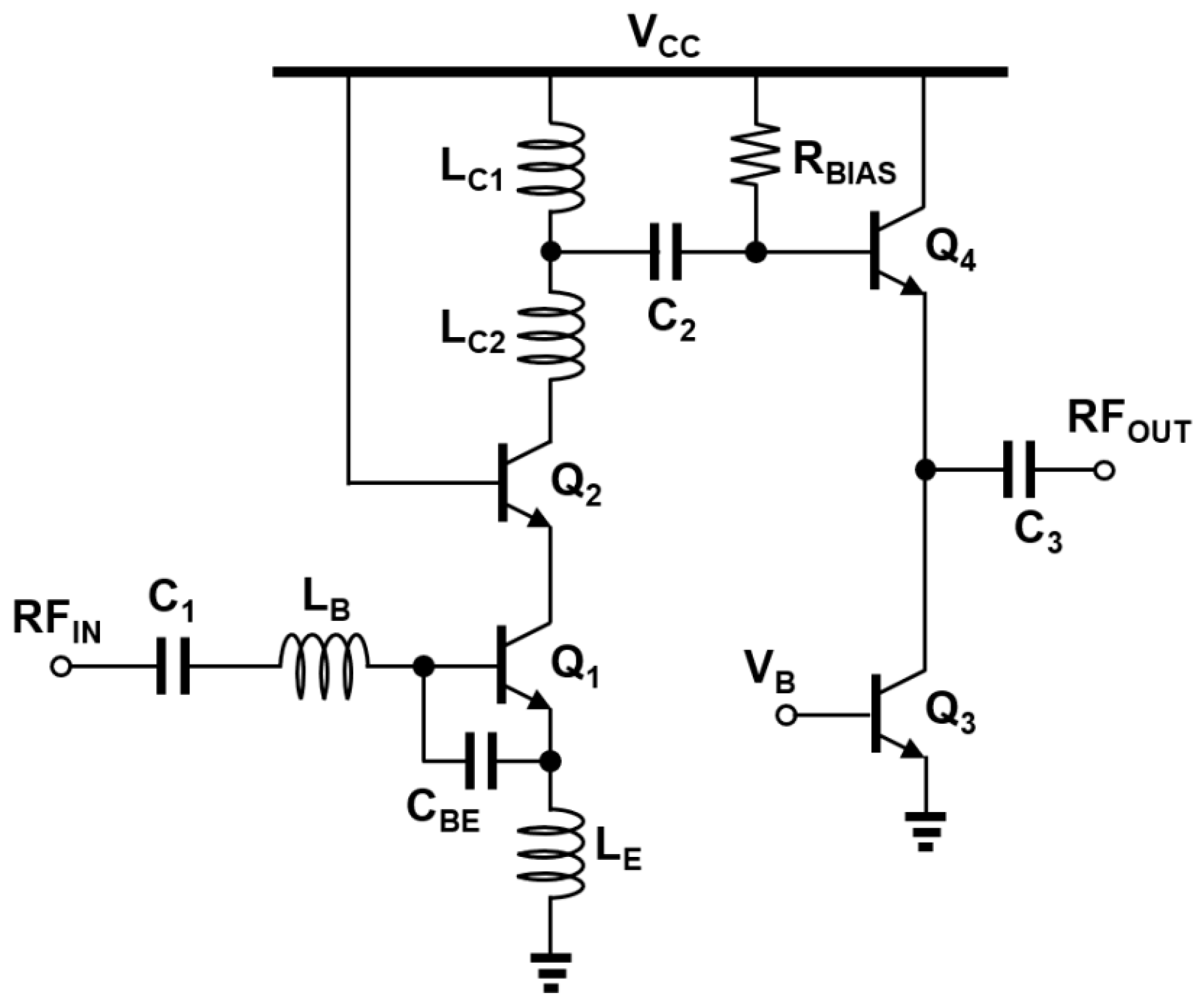

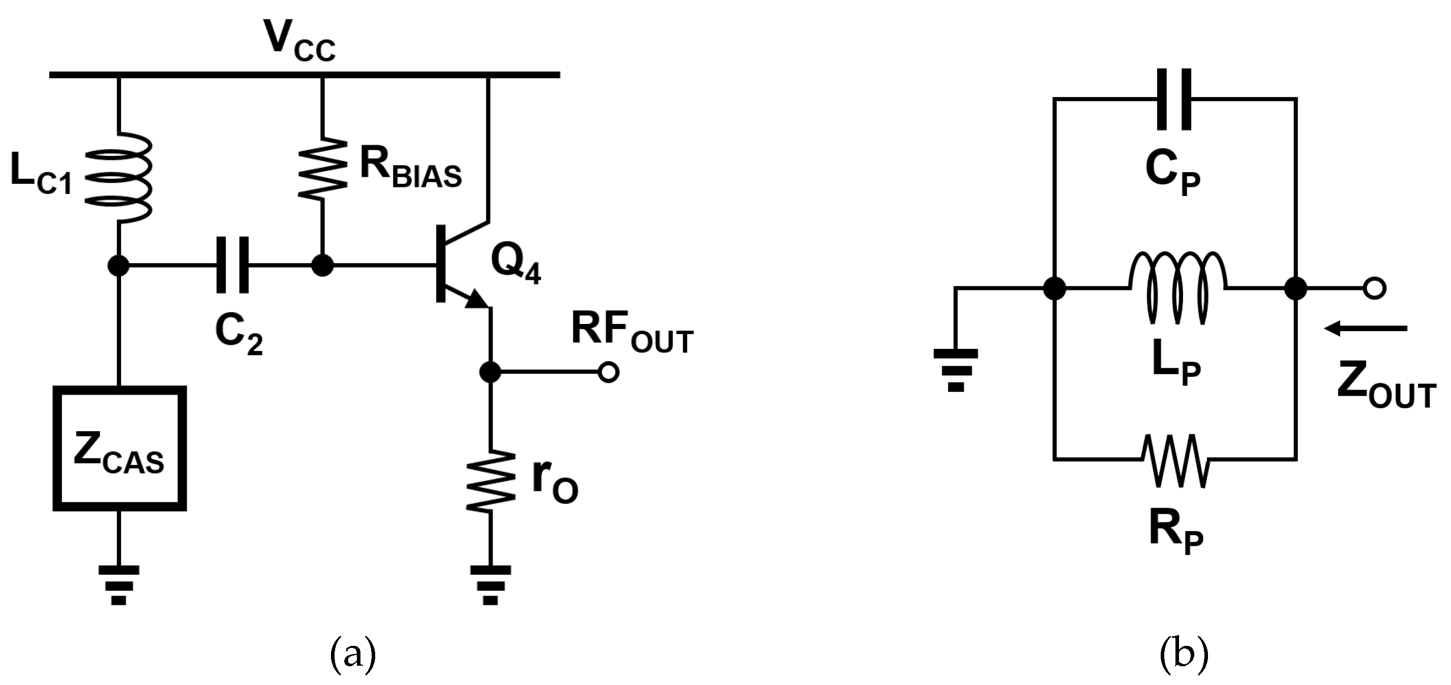
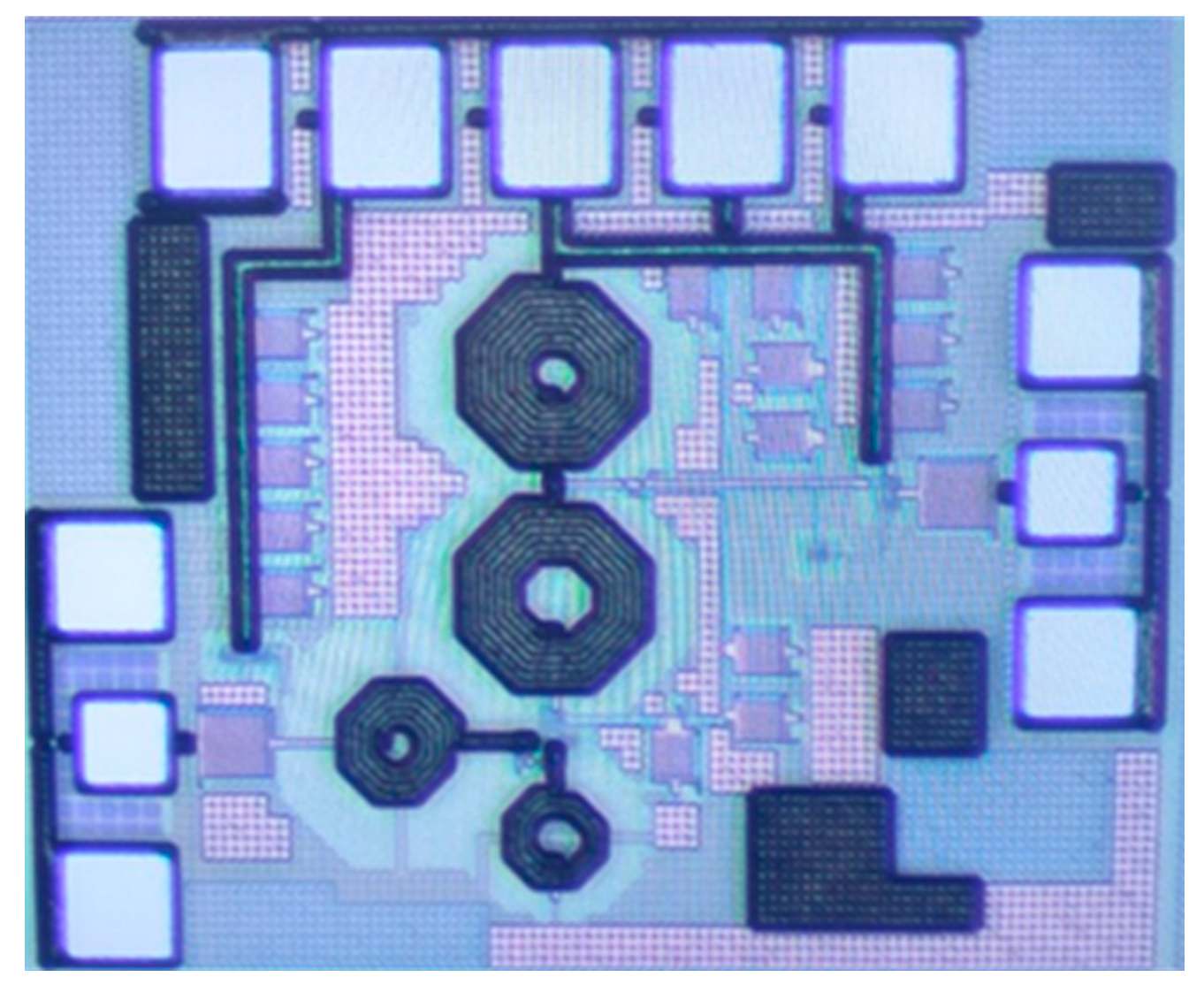
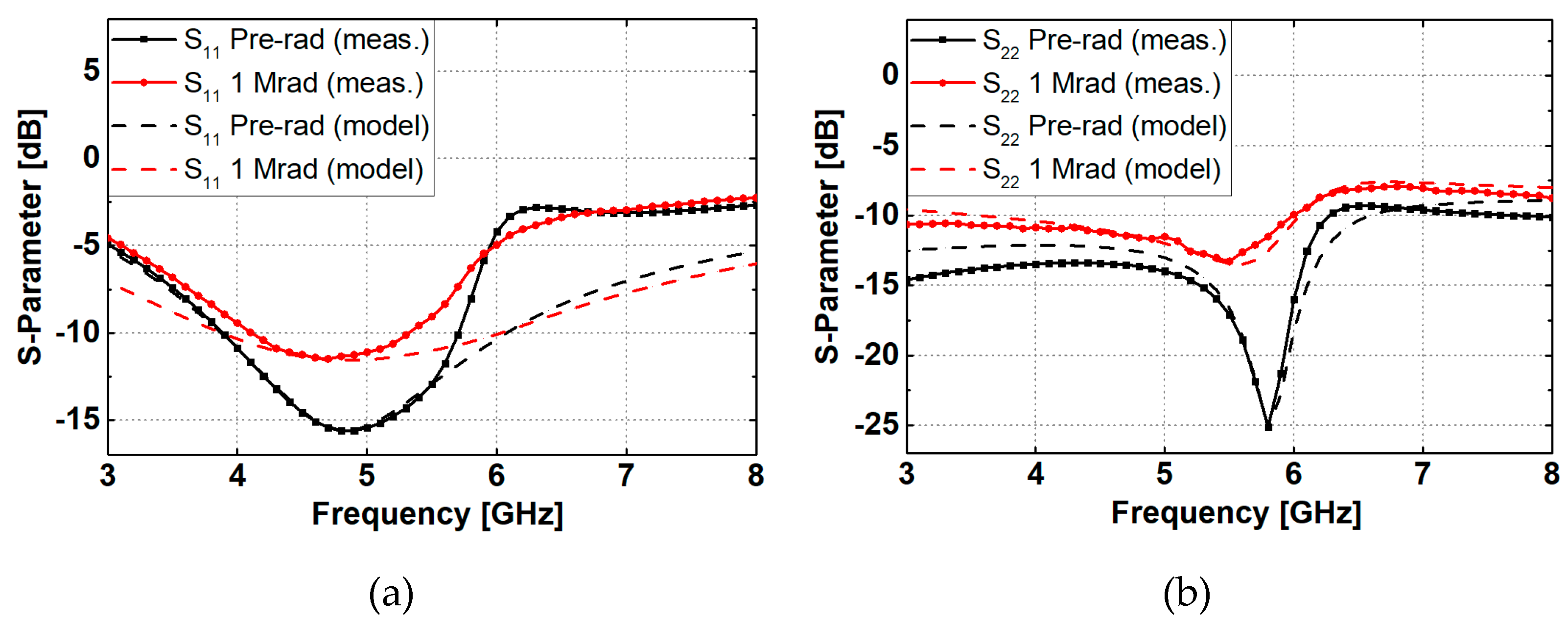
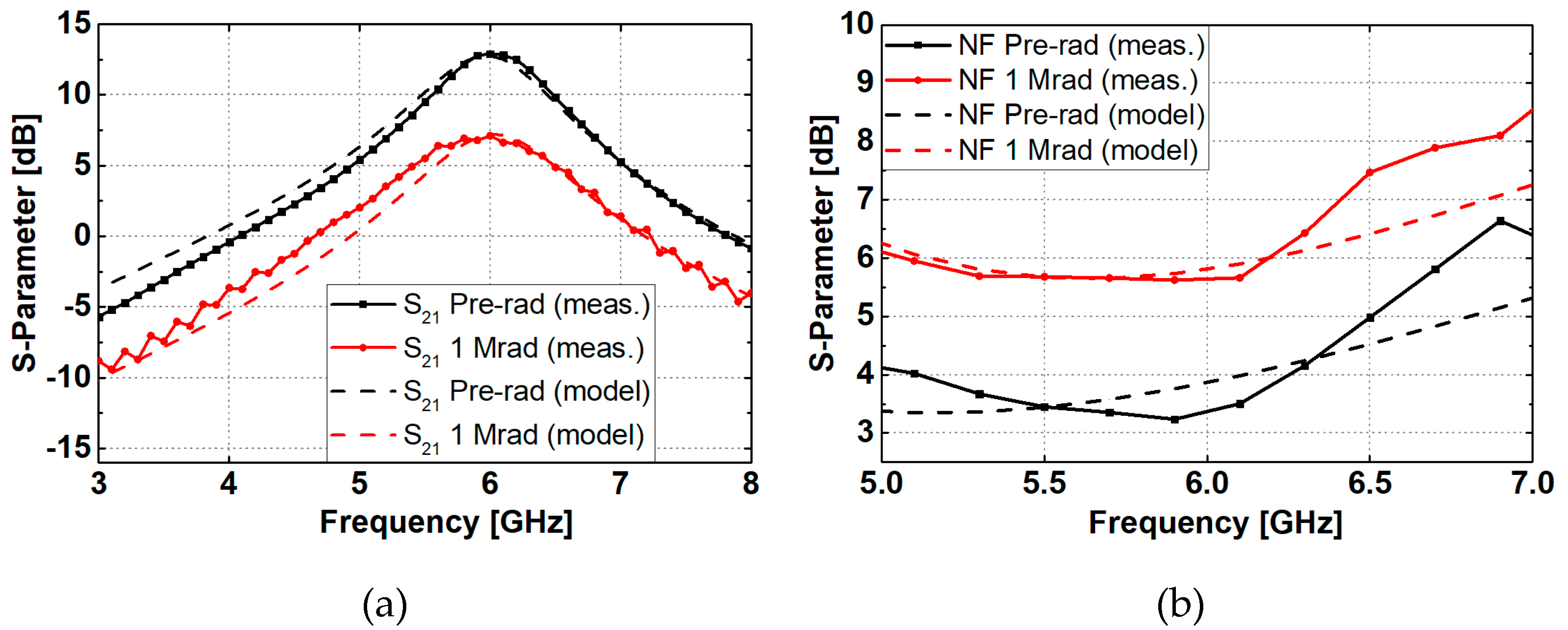
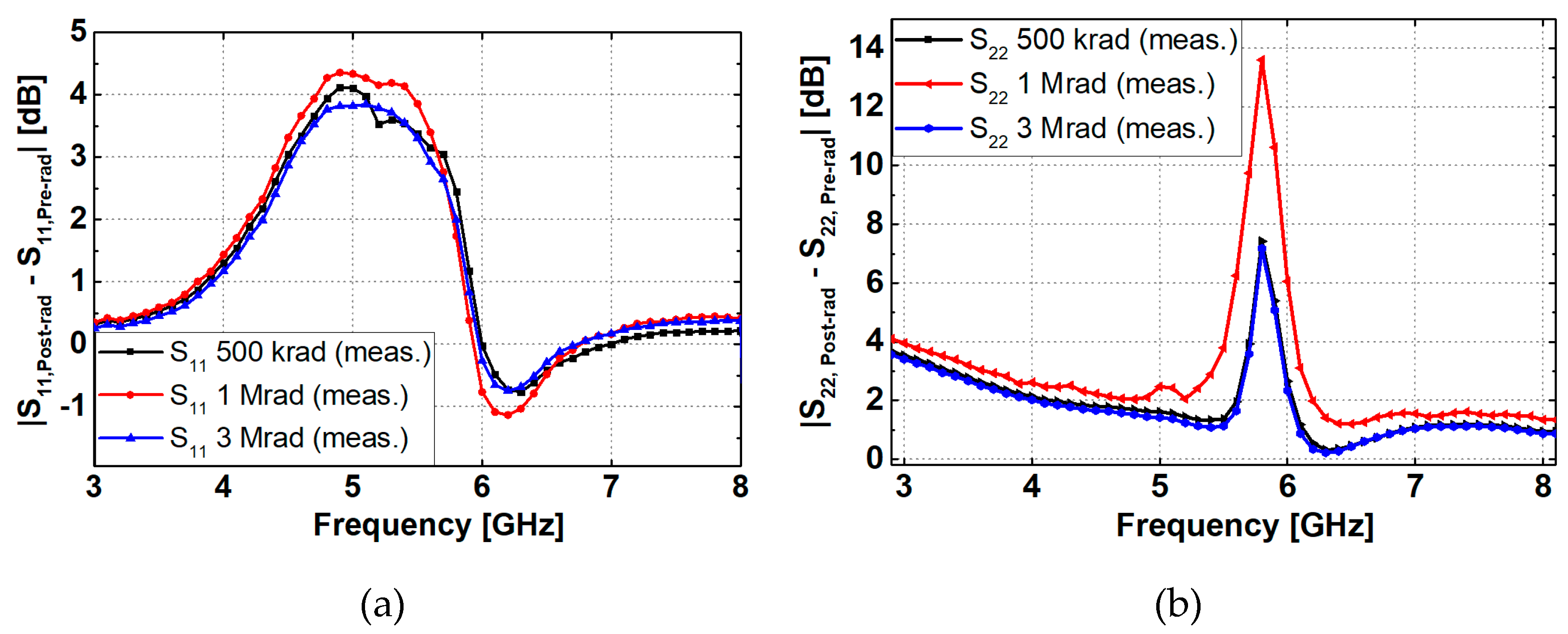
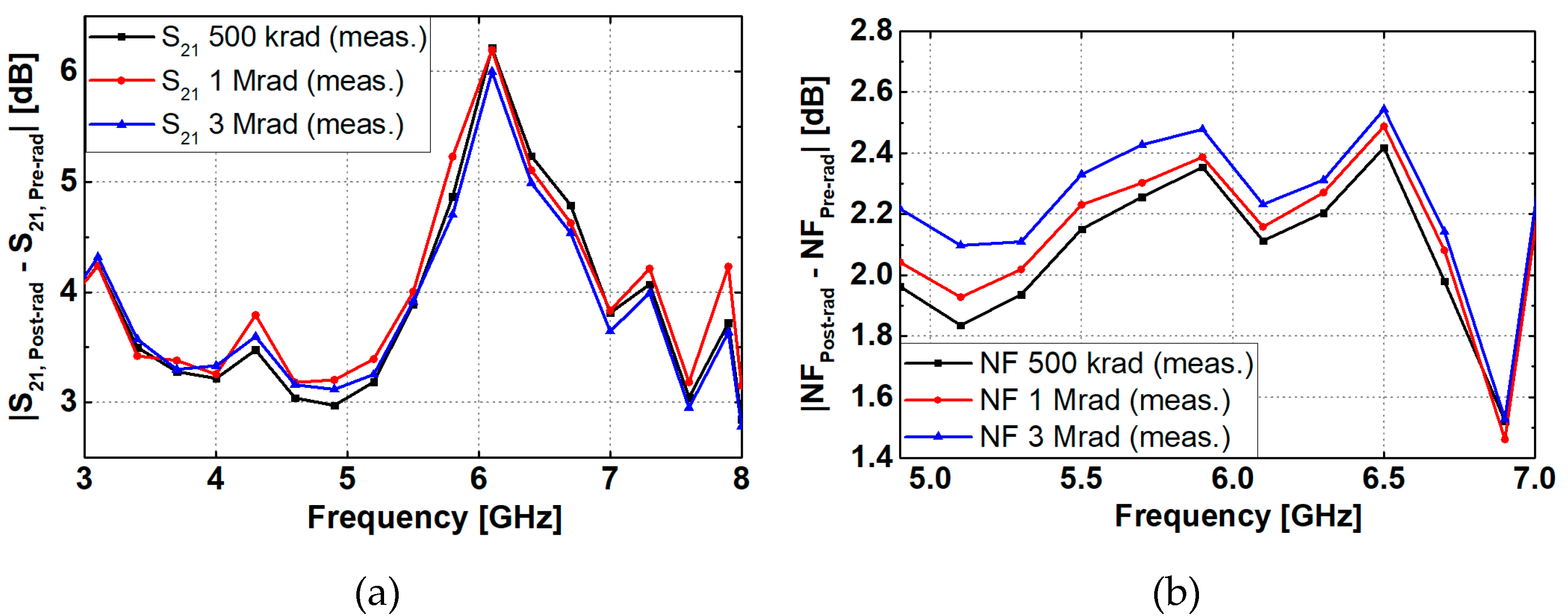
| Total dose | S11 | S22 | S21 | NF |
|---|---|---|---|---|
| Pre-rad | -15.62 dB | -23.66 dB | 12.89 dB | 3.45 dB |
| 500 krad | -11.52 dB | -17.11 dB | 7.34 dB | 5.6 dB |
| 1 Mrad | -11.27 dB | -11.19 dB | 7.14 dB | 5.66 dB |
| 3 Mrad | -11.79 dB | -17.36 dB | 7.55 dB | 5.78 dB |
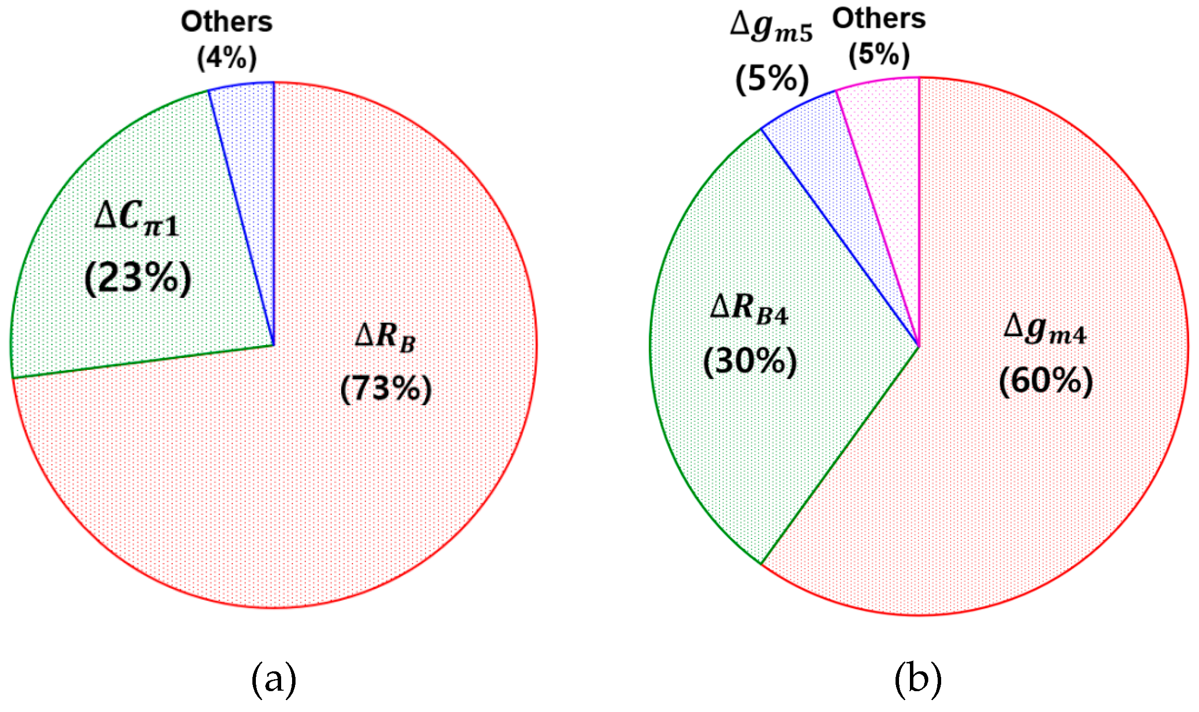
| Parameter | ΔS11 | ΔS22 | ΔS21 | ΔNF |
|---|---|---|---|---|
| Cπ | 23% | - | 8% | - |
| gm | - | 65% | 88% | 34% |
| RB | 73% | 30% | - | 56% |
| Parameter | Unit | Pre-rad | Post-rad (1 Mrad) |
|---|---|---|---|
| Cπ1, Cπ2 | fF | 250 | 330 |
| Cπ4 | fF | 240 | 320 |
| gm1, gm2 | mS | 45 | 30 |
| gm4 | mS | 17 | 11 |
| RB1, RB2 | Ω | 97 | 170 |
| RB4 | Ω | 80 | 140 |
Disclaimer/Publisher’s Note: The statements, opinions and data contained in all publications are solely those of the individual author(s) and contributor(s) and not of MDPI and/or the editor(s). MDPI and/or the editor(s) disclaim responsibility for any injury to people or property resulting from any ideas, methods, instructions or products referred to in the content. |
© 2024 by the authors. Licensee MDPI, Basel, Switzerland. This article is an open access article distributed under the terms and conditions of the Creative Commons Attribution (CC BY) license (http://creativecommons.org/licenses/by/4.0/).


