1. Introduction
Vibration isolation platforms are extensively used in the testing and environmental simulation of spacecraft. Traditional vibration isolation solutions include mechanical spring vibration isolation [
1,
2], air spring vibration isolation [
3,
4], and hydraulic vibration isolation [
5,
6]. However, these traditional solutions often have high stiffness, meaning that a significant change in force occurs with displacement. Magnetic levitation vibration isolation technology, an emerging method, has been widely promoted and applied in numerous fields in recent years due to its advantages of being contactless, high-precision, long-lived, and requiring low maintenance [
7,
8,
9,
10]. Magnetic levitation systems have lower stiffness, resulting in smaller changes in force with displacement, effectively reducing the interference from ground vibrations on the testing system.
Space telescopes, during their design and manufacturing stages, require a series of tests to verify their functionalities. The China Space Station Telescope (CSST) needs to test its optical imaging system under vacuum microgravity conditions, necessitating the design of a gravity compensation vibration isolation system that can operate in a vacuum. Air spring isolation is unsuitable for vacuum conditions [
11], mechanical spring isolation’s high stiffness does not provide precise positioning, but magnetic levitation isolation, due to its low stiffness and no gas leakage characteristics, meets the requirements well.
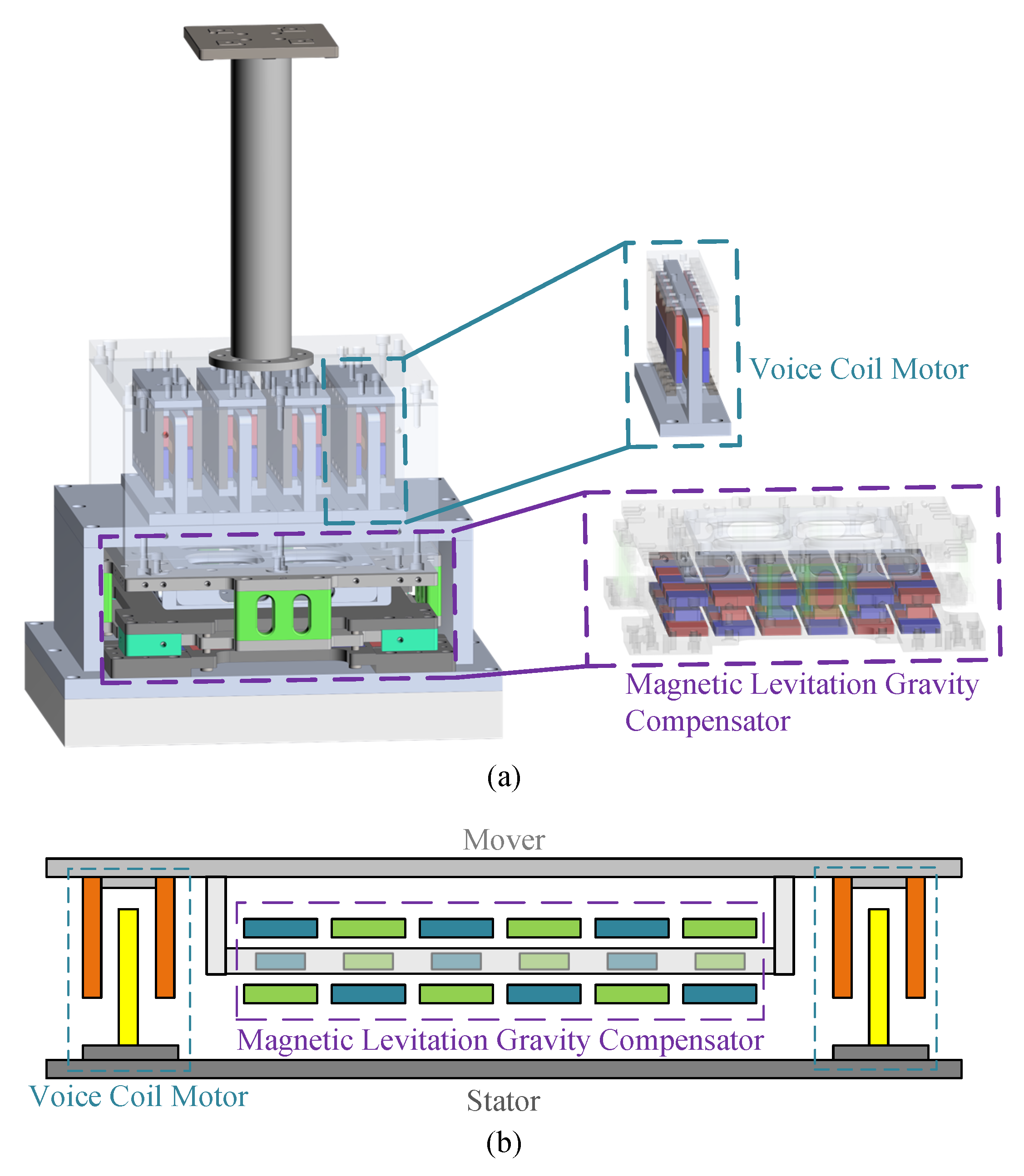
Figure 1 presents the basic configuration of the vibration isolation platform, mainly consisting of a permanent magnet array-type magnetic levitation gravity compensator [
12], voice coil motors, and a support frame. The gravity compensator and the voice coil motor’s armature are connected to the object being tested, where the gravity compensator plays a passive role in gravity compensation, and the voice coil motor actively isolates vibrations and compensates.
In recent years, there has been considerable research on voice coil motors for magnetic levitation and vibration isolation. In [
13], two different structures of voice coil motors designed for magnetic positioning devices were analyzed using finite element analysis (FEA) to study the impact of various parameters on thrust, eventually demonstrating a 40% difference in thrust between the two motors of the same volume. In [
14], a voice coil motor capable of generating constant thrust without energy input was proposed, optimizing the stiffness of constant thrust by altering the core iron shape, achieving a constant thrust of 20.9N and saving 23W of power consumption. Reference [
15] proposed a three-degree-of-freedom spherical voice coil motor for robotic joints, achieving a tilt range of ±30° along the X and Y axes and a rotation range of 360° around the Z-axis using annular magnets and multiple coils. In [
16], a two-degree-of-freedom voice coil motor was proposed, with the magnetic field analyzed using the equivalent current method, achieving a prototype thrust of 7.8 N and torque of 30 mN·m.
Existing literature primarily focuses on voice coil motors with small air gaps and low thrust. Given the displacement range required by the object under test and considering the manufacturing and assembly errors inherent in large test platforms, the voice coil motor designed in this paper requires a larger mechanical air gap to meet displacement needs and allowable errors. A larger air gap leads to increased magnetic reluctance, thereby reducing air gap flux density and thrust. This paper targets the design optimization of voice coil motors under large air gap conditions [
17,
18,
19,
20,
21].
This study starts from the large air gap of the voice coil motor, conducting an in-depth analysis and design. Furthermore, a FEA model was used, with thrust and thrust ripple as optimization objectives, to perform an optimization analysis of the voice coil motor. Lastly, a prototype was manufactured and experimentally validated. The experiments demonstrate good thrust linearity of the voice coil motor and a high degree of agreement with the finite element results.
2. Electromagnetic Design of the LAG-VCM
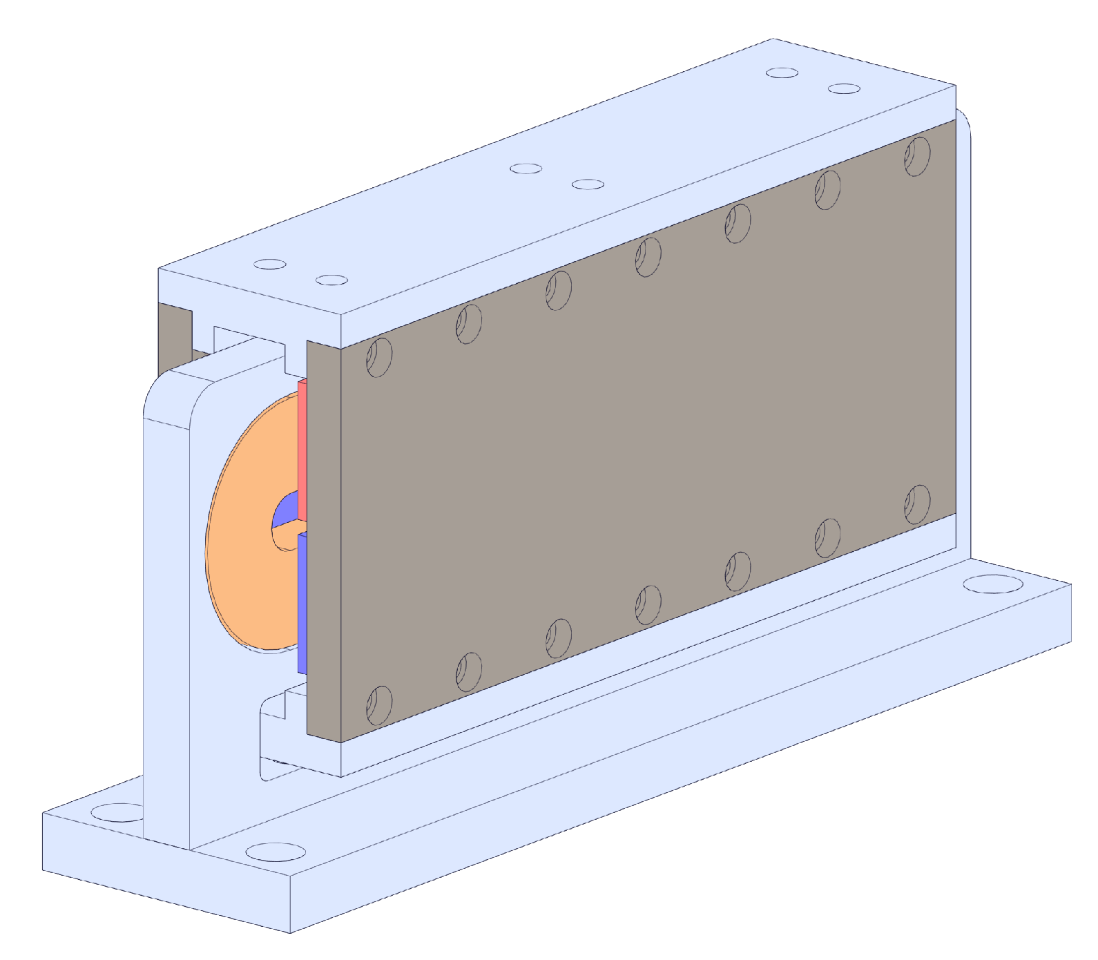
The voice coil motor designed in this study is a flat-type linear voice coil motor, as shown in
Figure 2. This motor is an active magnetic type, with the armature part being wire-free to eliminate wiring interference with the test component. Additionally, the coil generates Joule heat when energized. In a vacuum, the absence of convective cooling results in poor coil cooling. Since the tested optical system is sensitive to temperature, placing the coil on the stator allows for rapid heat conduction to the ground cooling source, avoiding interference with the optical system. The design requirements of the voice coil motor are shown in
Table 1.
The Lorentz force acting on the energized conductor in the magnetic field produced by the permanent magnets is given by
where is lorentz force on the conductor; N is the number of turns in the conductor; is air gap magnetic field strength.
The expression for the air gap magnetic field strength can be obtained using the Equivalent Magnetic Circuit Method:
where is the remanence of the permanent magnet; is the relative magnetic permeability of air; is air gap length; is leakage coefficient; is the height of permanent magnet.
Initially, the air gap flux density is preset, considering that a smaller air gap flux density should be assumed due to the larger air gap. Then, based on the current conditions, the size of the coil is calculated, followed by the calculation of the width and height of the permanent magnet, thus completing the electromagnetic design process of the voice coil motor.
3. Finite Element Analysis and Optimization of the LAG-VCM
3.1. Finite Element Analysis Validation of the LAG-VCM
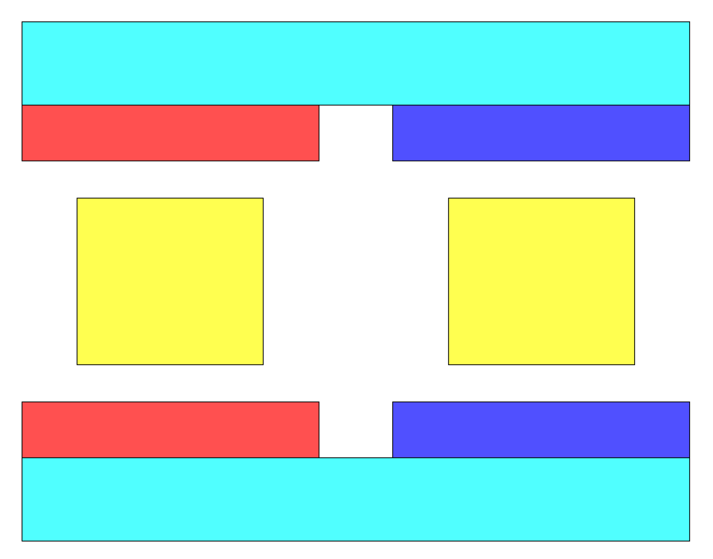
The finite element analysis model was established in finite element analysis software based on the results of electromagnetic design, as shown in
Figure 3.
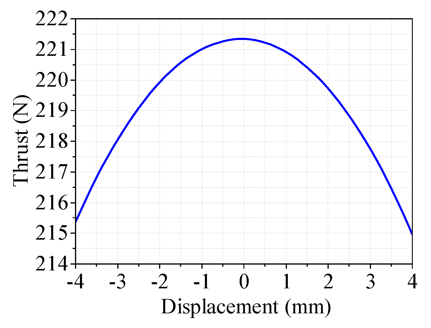
When the rated current is applied to the coil, the thrust variation with position is illustrated in
Figure 4. The maximum thrust of 221.3 N occurs at the coil’s center position and decreases gradually with increasing coil displacement. At the center position, the thrust did not reach the design target.
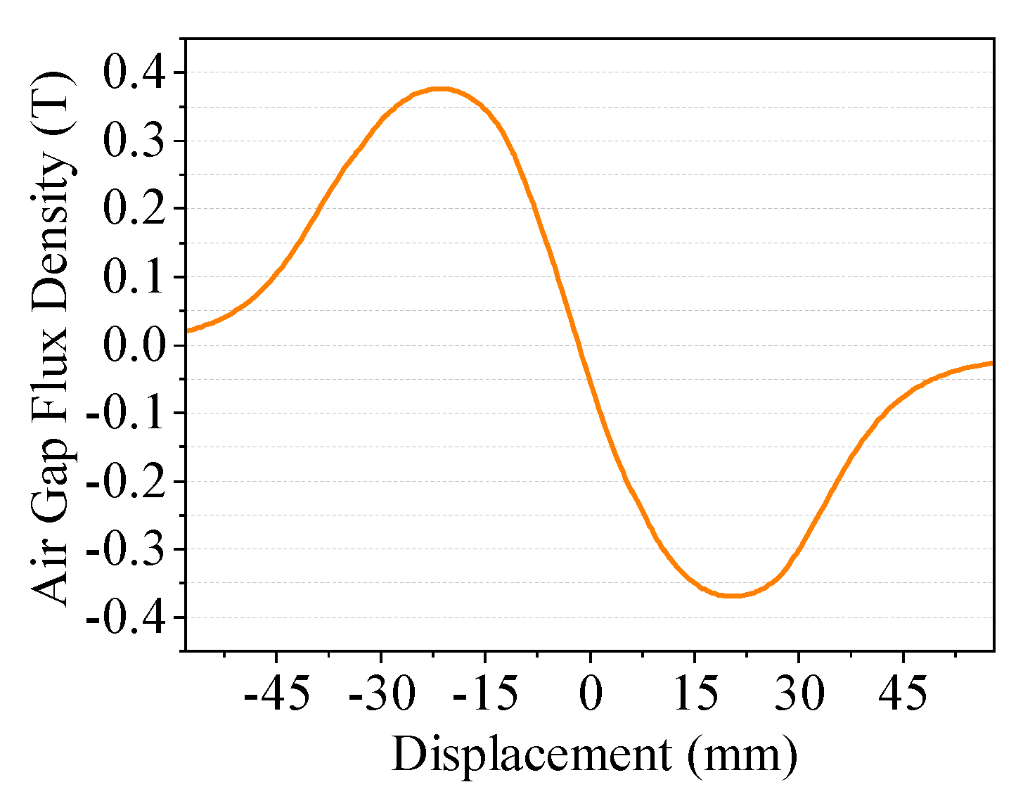
The magnetic flux density in the middle of the motor’s air gap is depicted in
Figure 5. At the air gap centerline, the maximum flux density is 0.35T, which is lower than the preset air gap flux density in electromagnetic design. This is due to the significant leakage flux associated with the large equivalent air gap and possible saturation in the yoke.
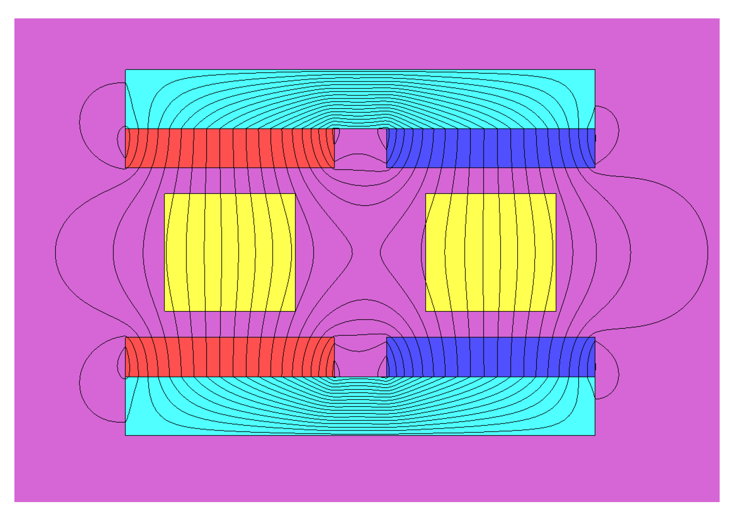
The distribution of flux lines in the voice coil motor is shown in
Figure 6. The flux lines primarily form a closed magnetic circuit through the permanent magnet-air gap-yoke path, but significant leakage occurs between adjacent magnets. This is mainly due to the large equivalent air gap of the voice coil motor, which should be reduced in subsequent optimization.
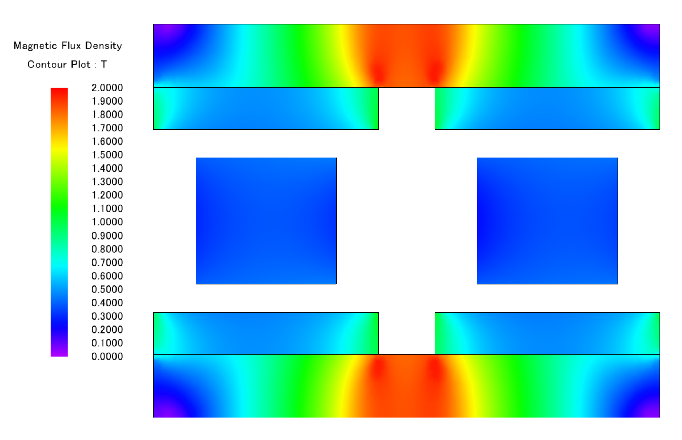
The magnetic flux density map of the voice coil motor is presented in
Figure 7. It shows a certain degree of saturation in the center of the yoke, which weakens the motor’s thrust and increases thrust ripple. In future optimization, the height of the yoke should be increased to mitigate this saturation.
3.2. Finite Element Optimization of the LAG-VCM
Finite element optimization was carried out using parameter scanning to analyze the impact of different parameters on the motor’s thrust and thrust ripple. While increasing the air gap flux density to enhance motor thrust, the aim was to minimize the armature mass for improved dynamic response and consider practical manufacturing costs.
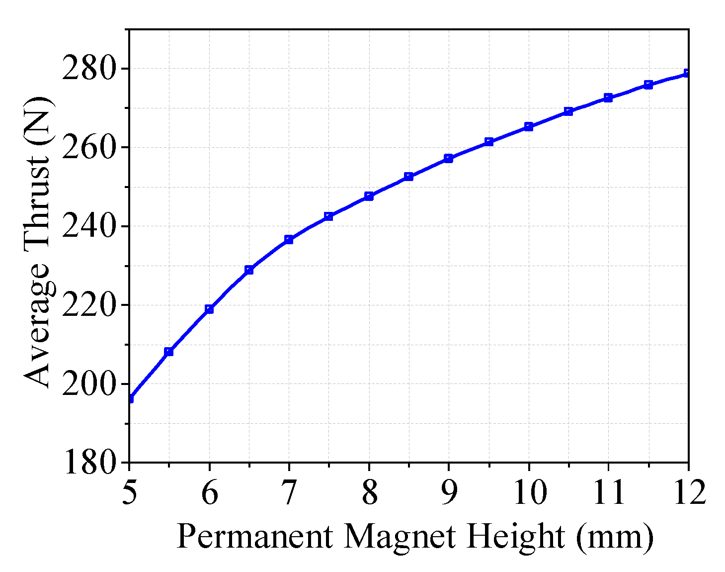
First, the effect of the permanent magnet height on the average thrust and thrust ripple of the voice coil motor was analyzed. The relationship between the average thrust and the height of the permanent magnets is shown in
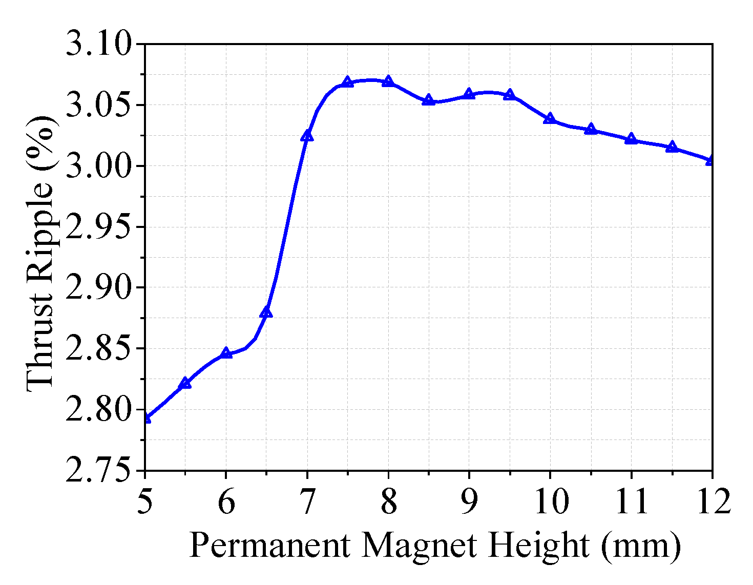
Figure 8. The motor’s thrust increases with the height of the permanent magnets due to increased magnetic potential and consequent increase in air gap flux density. When the height of the magnets exceeds 7mm, the increase in thrust slows due to further saturation of the yoke. The thrust ripple varies with the height of the permanent magnets, as shown in
Figure 9. The thrust ripple initially increases and then stabilizes with increasing height. This is due to increased unevenness in air gap flux density caused by saturation, leading to higher thrust ripple. Considering both average thrust and thrust ripple, a height of 8mm was chosen for the permanent magnets.
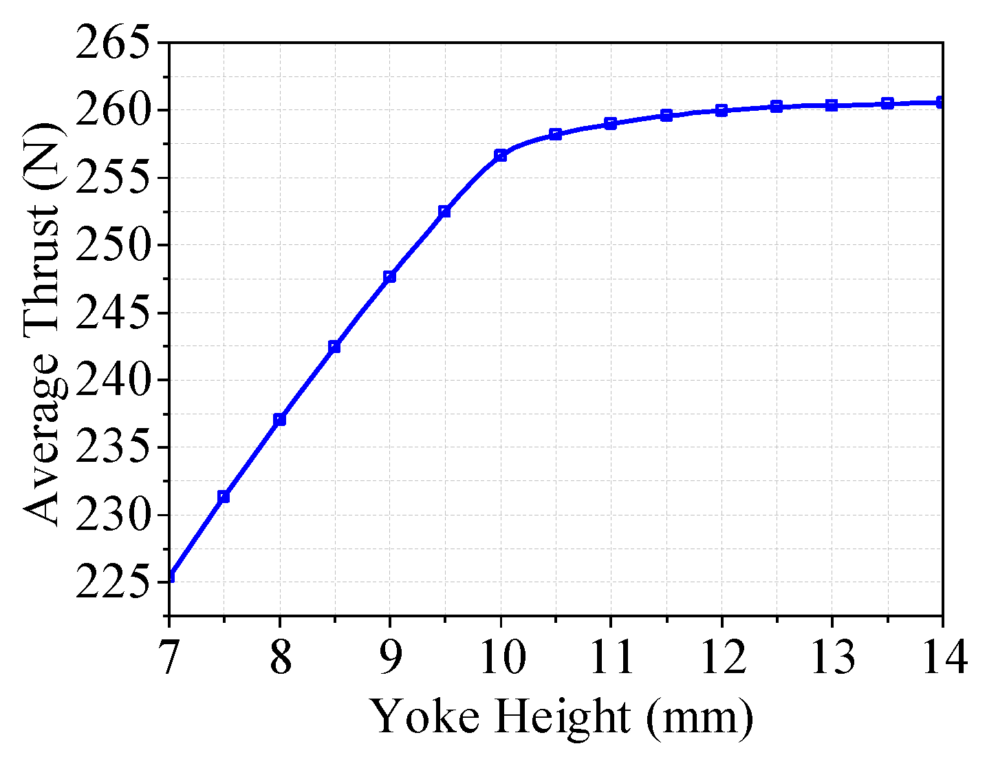
Changes in yoke height were analyzed in terms of average thrust and thrust ripple of the voice coil motor. The relationship between the average thrust and yoke height is shown in
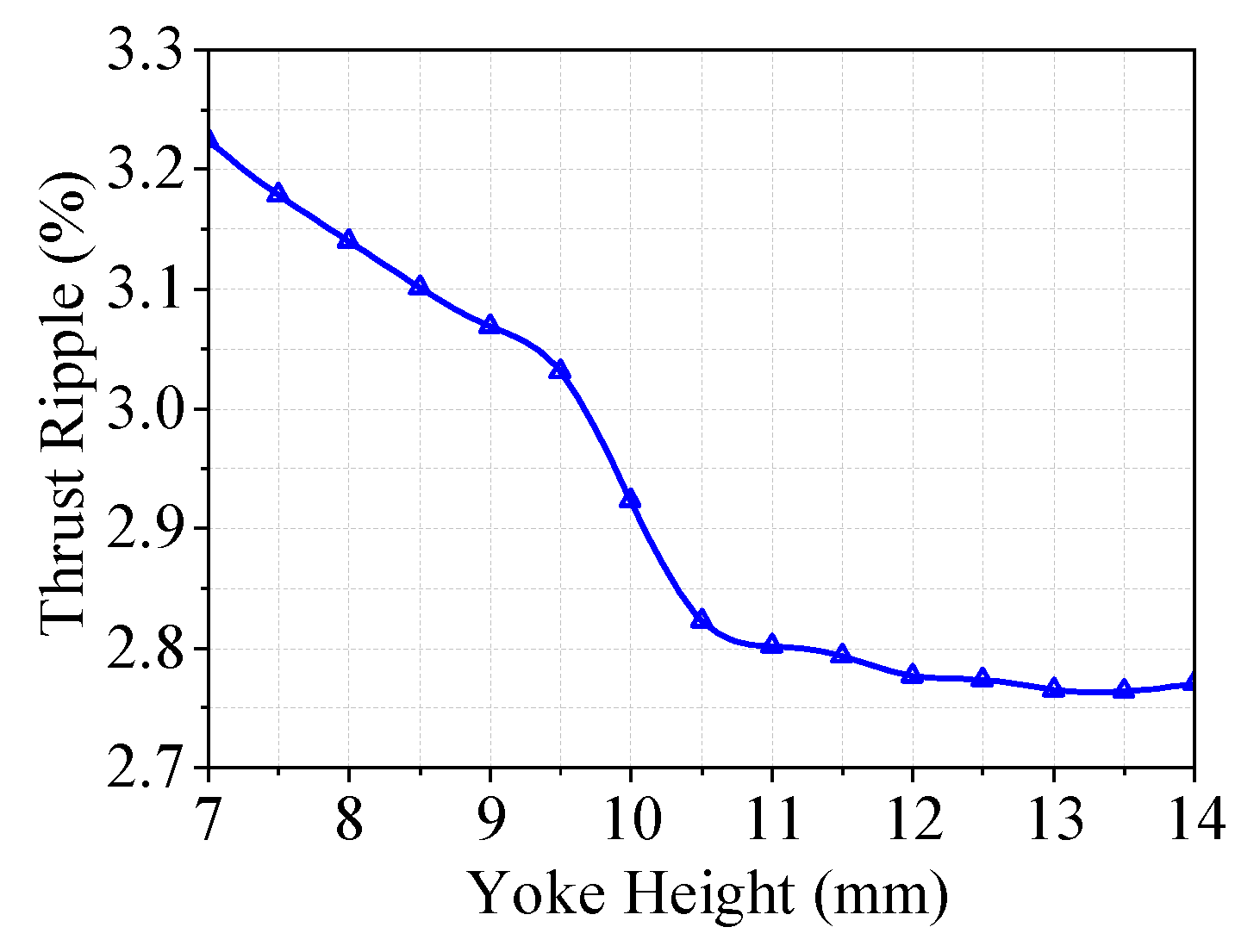
Figure 10, where the average thrust initially increases and then stabilizes with increased yoke height due to decreasing saturation levels. The relationship between thrust ripple and yoke height is presented in
Figure 11, where the thrust ripple decreases and then stabilizes as the yoke height increases, improving the uniformity of the air gap magnetic field. Therefore, a yoke height of 11 mm was chosen.
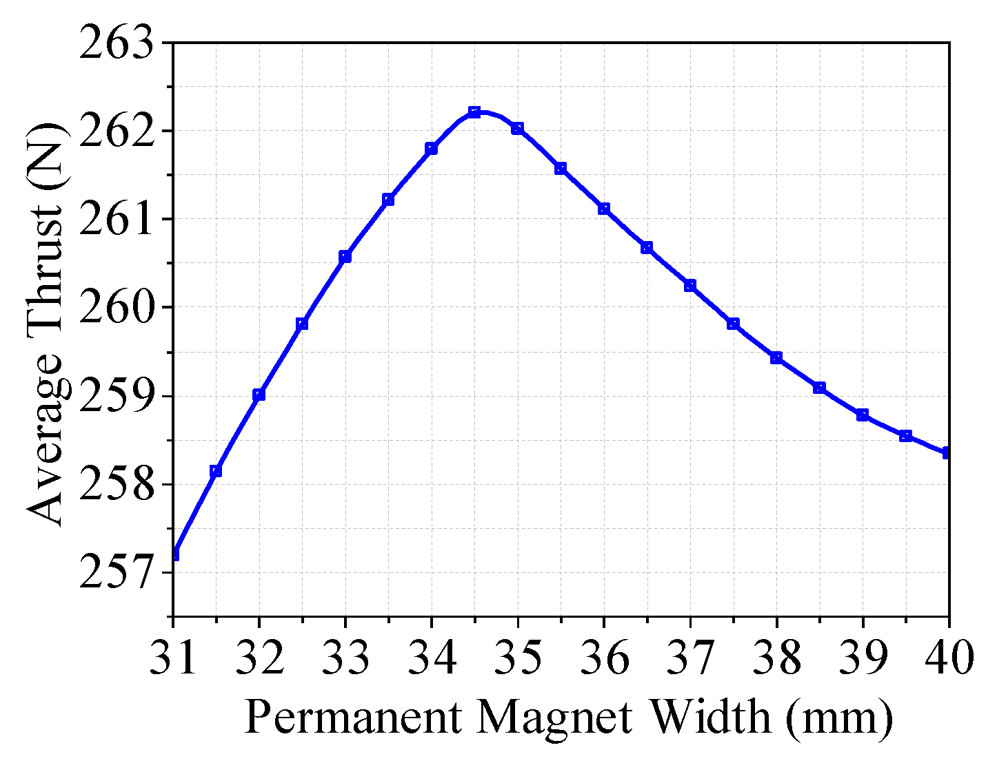
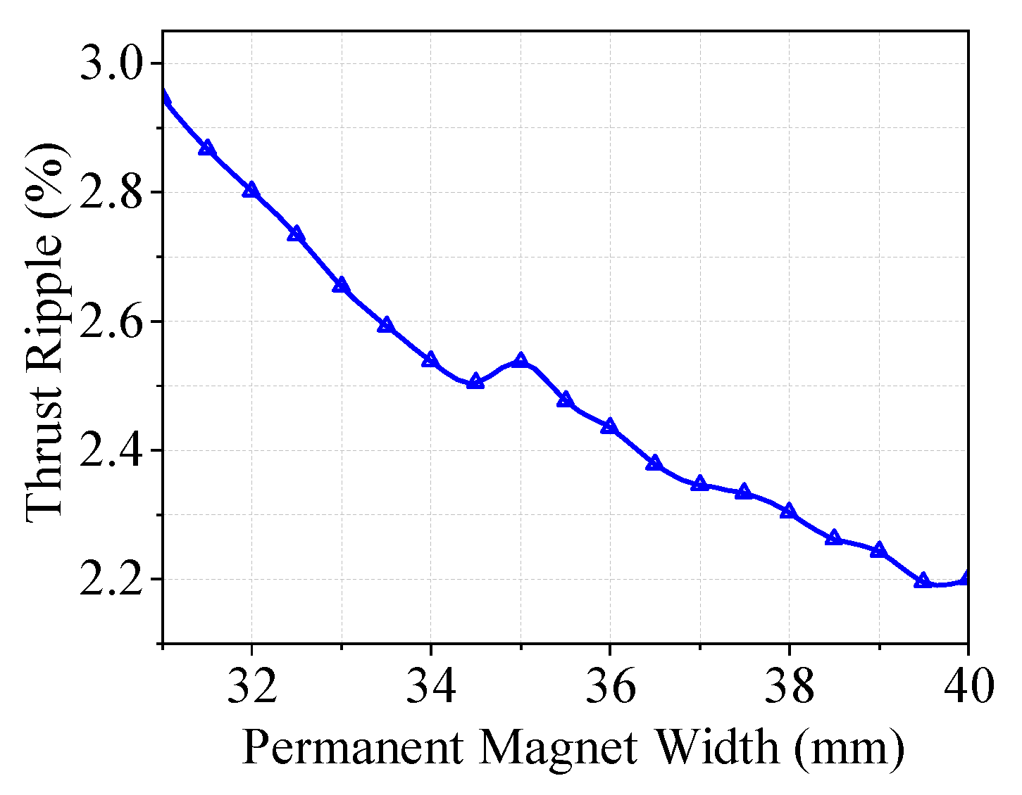
The effect of changing the width of the permanent magnets on the average thrust and thrust ripple was calculated, as shown in
Figure 12 and
Figure 13. Considering subsequent optimization margins and manufacturing costs, a width of 36mm was chosen for the permanent magnets.
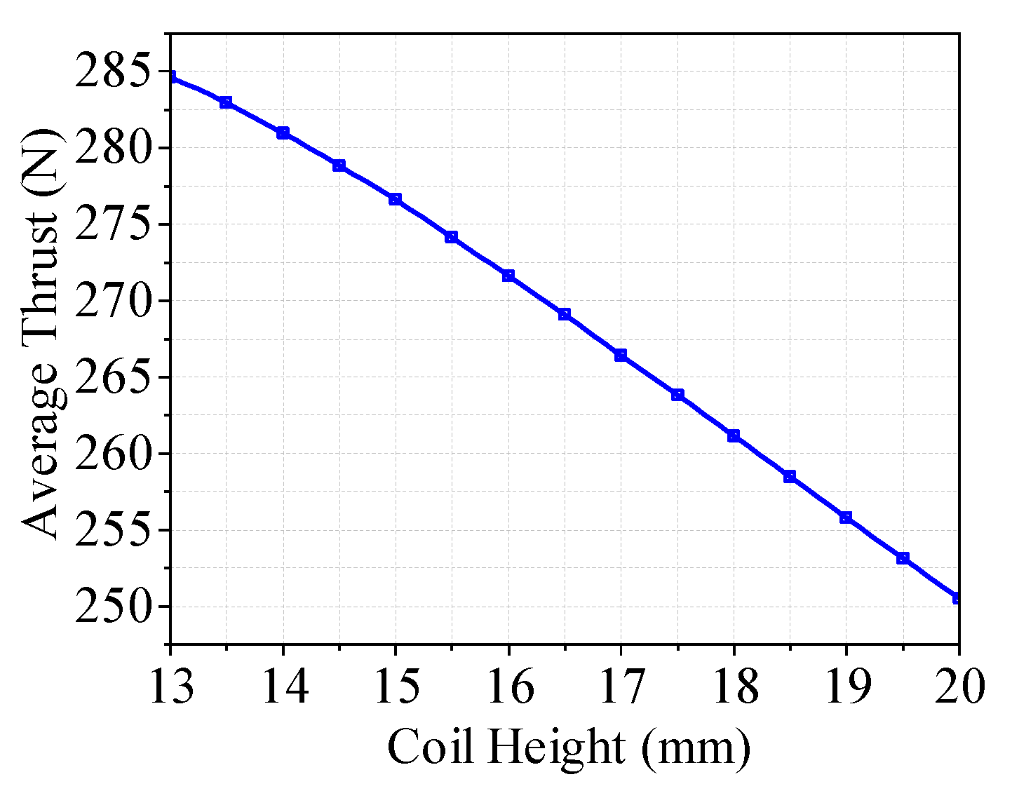
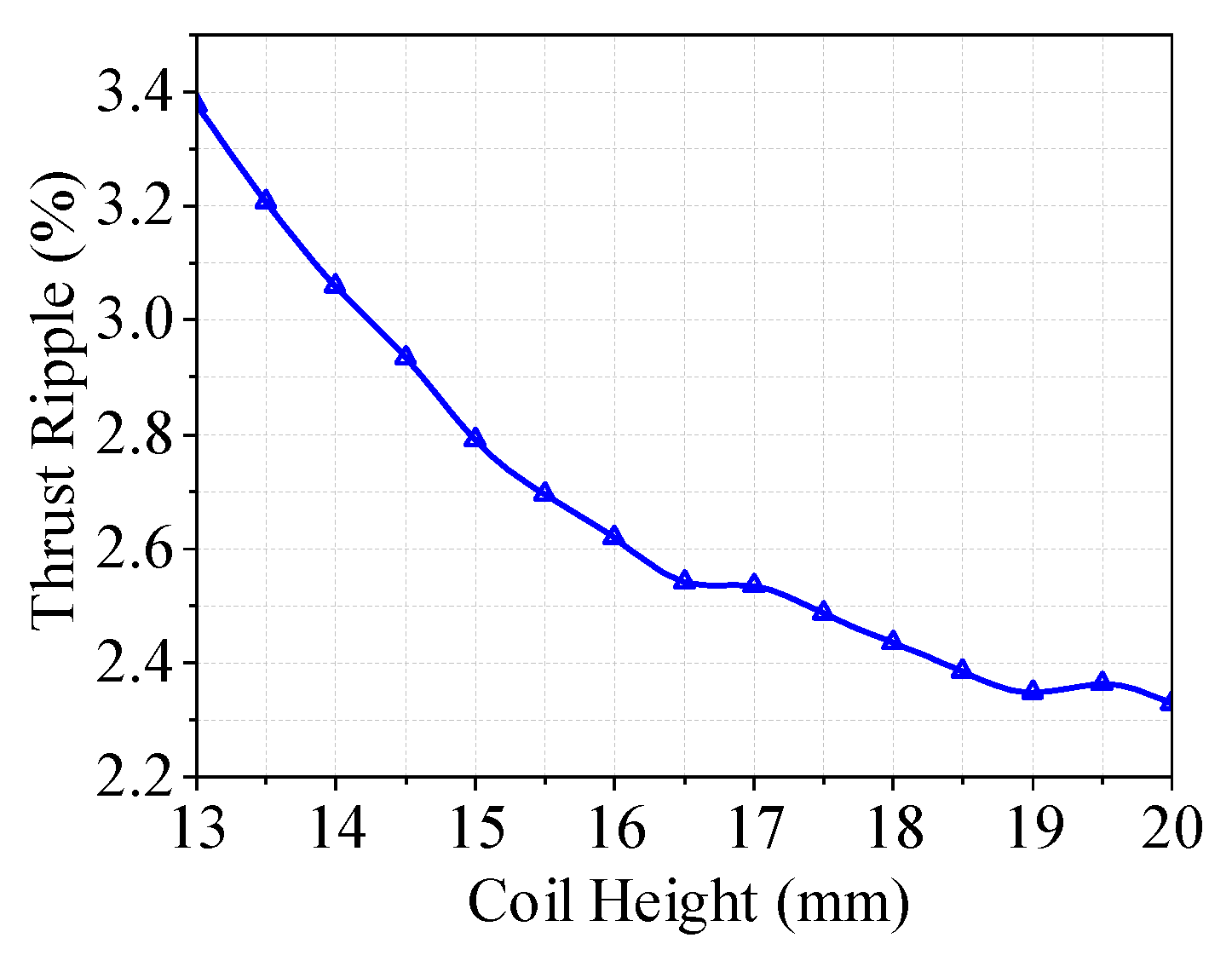
By keeping the coil area and number of turns constant and changing the coil height, the average thrust and thrust ripple were calculated, as shown in
Figure 14 and
Figure 15. As the coil height increases, the average thrust gradually decreases due to the increased equivalent air gap and increased magnetic reluctance in the air gap, leading to a decrease in air gap flux density and, consequently, average thrust. The thrust ripple decreases with increasing coil height as the coil width simultaneously decreases, improving the uniformity of the internal magnetic field, thus reducing motor thrust ripple. After considering both average thrust and thrust ripple, a coil height of 15mm and a width of 24 mm were selected.
4. Prototype and Experimentation of the LAG-VCM
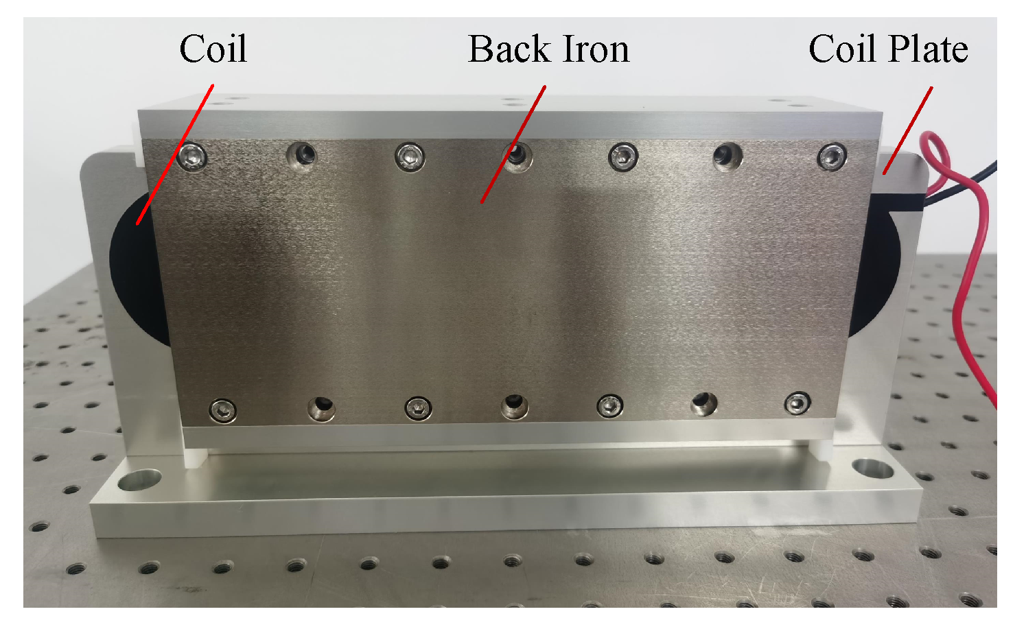
Following the electromagnetic design and finite element optimization, a prototype of LAG-VCM was manufactured as shown in
Figure 16. The back iron material is S10C, while the remaining support structures are manufactured from 7075 aluminum alloy, and the coil is encapsulated with epoxy resin. There is no physical contact between the mover and the stator. The total mass of the mover is 6.95 kg and the mass of the stator is 2.8 kg. The main parameters of the prototype are given in
Table 2.
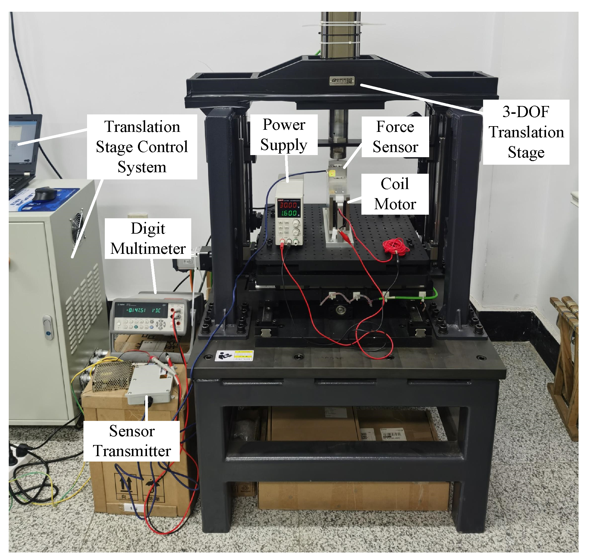
The thrust testing platform for the large air-gap voice coil motor is illustrated in
Figure 17. A three-degree-of-freedom (3-DOF) electrically controlled translation stage facilitates displacement in the direction of the motor movement, with a minimum displacement resolution of 0.1 mm. The DC power supply, model UTP1306S, provides a controllable direct current to the coil of the voice coil motor. A force sensor (Transcell, BAB-20MT, Capacity: 20 kg) and a multimeter (Agilent, 34411A6, Digital resolution:
) are used to test the thrust of the voice coil motor.
To enhance the accuracy of the thrust testing, the voice coil motor is positioned vertically, and the current is adjusted to ensure that the thrust is directed upwards. This arrangement negates the effect of the mover’s weight and eliminates frictional interference, due to the absence of physical contact between the mover and the stator. The first step involves testing the linearity of the thrust, with the mover positioned at the center and the current magnitude adjusted. Subsequently, the 3-DOF translation stage’s z-axis is controlled for incremental movement, allowing for the measurement of the voice coil motor’s thrust at various positions and under different current magnitudes.
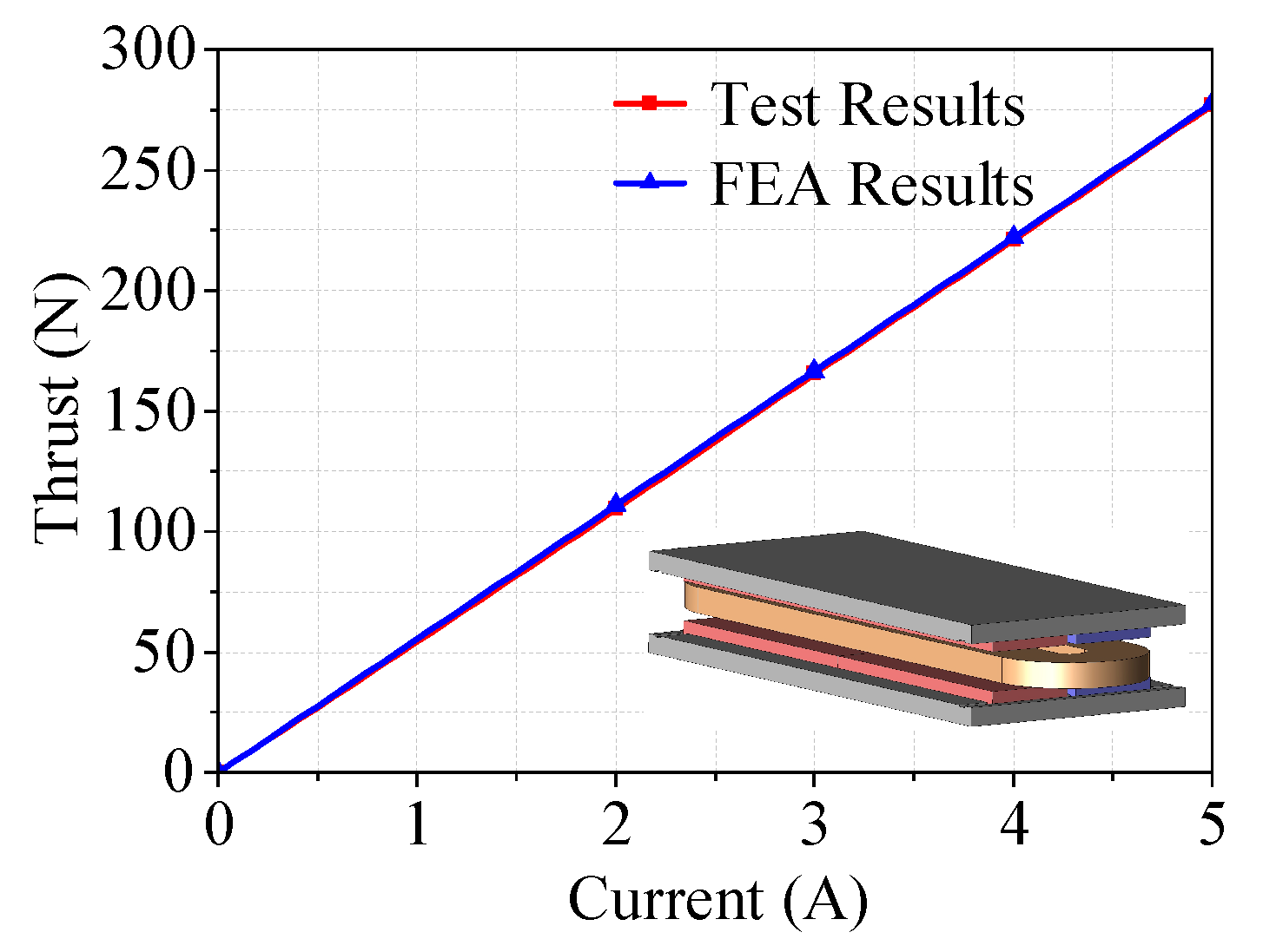
The relationship between thrust and current is illustrated in
Figure 18. It can be observed that the thrust changes linearly with the current, indicating excellent linearity of the prototype’s thrust. At the rated current of 5 A, the thrust is 277.11 N, which meets the design requirements.A three-dimensional finite element model was established based on the actual manufacturing parameters for simulation. The error between simulation and test results was less than 1%, aligning well with the FEA results.
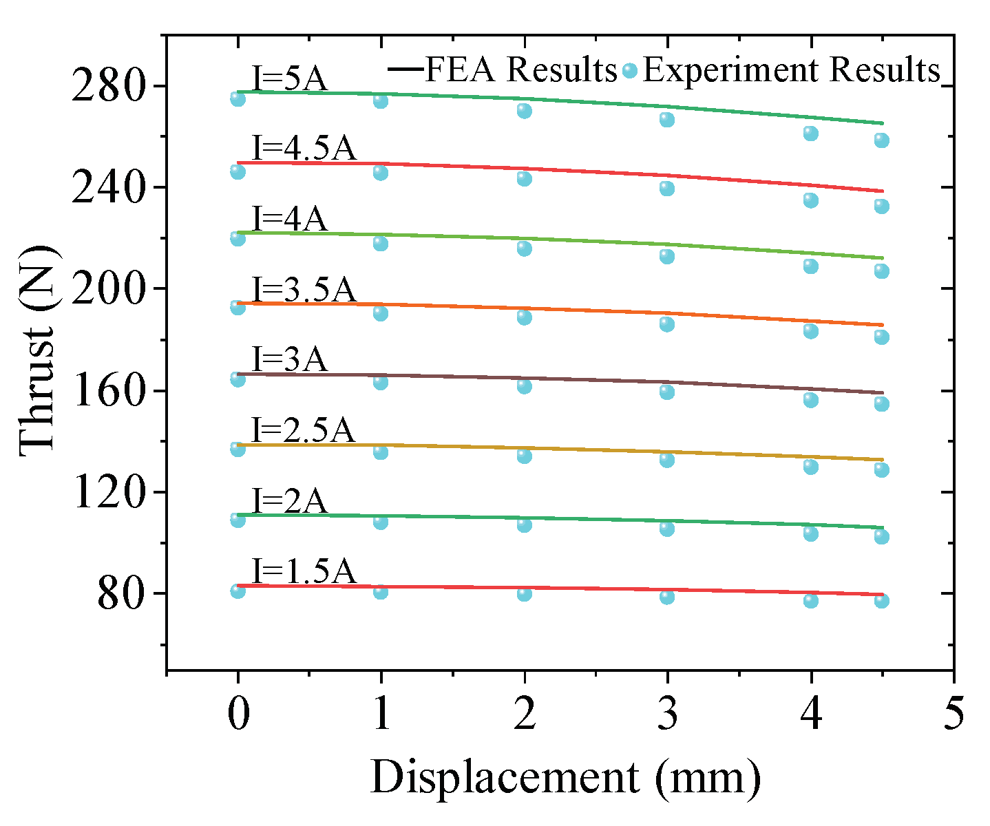
Figure 19 shows the relationship between thrust and displacement at different current magnitudes. At various currents, the thrust ripple of the voice coil motor is consistently 6% and the thrust ripple is low. At rated current (
I = 5 A), within a displacement of 4.5 mm, the maximum absolute variation of the thrust is 16.2 N. The test results are slightly lower than the FEA results, which may be attributed to the insufficient magnetization of the permanent magnets.
5. Conclusions
This paper presented the design of a voice coil motor for use in a magnetic levitation vibration isolation platform, featuring a large air gap. Initially, the Equivalent Magnetic Circuit Method was employed for the electromagnetic design of the voice coil motor. Subsequently, finite element methods were used for modeling the motor, analyzing the impact of various design parameters on the motor’s thrust and thrust ripple, and optimizing the motor. Based on the optimization results, a prototype was manufactured, and the test results of the prototype met the design requirements. The next step should involve further analysis of the motor’s heat dissipation in a vacuum to minimize the temperature rise’s impact on the tested system.
Author Contributions
Conceptualization, Junren Mu and He Zhang; methodology, He Zhang.; software, Junren Mu; validation, Junren Mu and He Zhang; formal analysis, He Zhang; investigation, Junren Mu; resources, He Zhang; data curation, He Zhang; writing—original draft preparation, Junren Mu; writing—review and editing, He Zhang; visualization, Junren Mu; supervision, He Zhang; project administration, He Zhang; funding acquisition, He Zhang. All authors have read and agreed to the published version of the manuscript.
Funding
This research is supported by the National Natural Science Foundation of China, under grant (52377044).
Data Availability Statement
The original contributions presented in the study are included in the article, further inquiries can be directed to the corresponding author.
Conflicts of Interest
The authors declare no conflict of interest.
Abbreviations
The following abbreviations are used in this manuscript:
| LAG-VCM |
Large Air-Gap Voice Coil Motor |
| FEA |
Finite Element Analysis |
References
- Ling, Yuhong; Wu, Shan; Gu, Jingxin; Lai, Hongtao. A novel ring spring vibration isolator for metro superstructure. Applied Sciences 2021, 11, 8422. [CrossRef]
- Araki, Yoshikazu; Asai, Takehiko; Kimura, Kosuke; Maezawa, Kosei; Masui, Takeshi. Nonlinear vibration isolator with adjustable restoring force. Journal of Sound and Vibration 2013, 332, 6063–6077. [Google Scholar] [CrossRef]
- Voigtländer, Bert; Coenen, Peter; Cherepanov, Vasily; Borgens, Peter; Duden, Thomas; Tautz, F Stefan. Low vibration laboratory with a single-stage vibration isolation for microscopy applications. Review of Scientific Instruments 2017, 88. [Google Scholar] [CrossRef]
- Qu, Di; Liu, Xiandong; Liu, Guangtong; Bai, Yifan; He, Tian. Analysis of vibration isolation performance of parallel air spring system for precision equipment transportation. Measurement and Control 2019, 52, 291–302. [Google Scholar] [CrossRef]
- Law, M; Wabner, M; Colditz, A; Kolouch, M; Noack, S; Ihlenfeldt, S. Active vibration isolation of machine tools using an electro-hydraulic actuator. CIRP Journal of Manufacturing Science and Technology 2015, 10, 36–48. [Google Scholar] [CrossRef]
- Henderson, Jean-Paul; Plummer, Andrew; Johnston, Nigel. An electro-hydrostatic actuator for hybrid active-passive vibration isolation. International Journal of Hydromechatronics 2018, 1, 47–71. [Google Scholar] [CrossRef]
- Xu, Daolin; Yu, Qiping; Zhou, Jiaxi; Bishop, SR. Theoretical and experimental analyses of a nonlinear magnetic vibration isolator with quasi-zero-stiffness characteristic. Journal of Sound and Vibration 2013, 332, 3377–3389. [Google Scholar] [CrossRef]
- Yan, Bo; Yu, Ning; Wang, Zhihao; Wu, Chuanyu; Wang, Sen; Zhang, Wenming. Lever-type quasi-zero stiffness vibration isolator with magnetic spring. Journal of Sound and Vibration 2022, 527, 116865. [Google Scholar] [CrossRef]
- Ma, Zhaozhao; Zhou, Ruiping; Yang, Qingchao; Lee, Heow Pueh; Chai, Kai. A semi-active electromagnetic quasi-zero-stiffness vibration isolator. International Journal of Mechanical Sciences 2023, 252, 108357. [Google Scholar] [CrossRef]
- Chen, Xu; Zhao, Jinglei; Jing, Yan; Cao, Xijun; Yuan, Shujin; Luo, Jun; Pu, Huayan. A novel permanent magnet vibration isolator with wide stiffness range and high bearing capacity. Mechatronics 2024, 98, 103119. [Google Scholar] [CrossRef]
- Zhao, Yamin; Cui, Junning; Bian, Xingyuan; Zou, Limin; Liang, Shitong; Wang, Li. Study on Performance of an air spring isolator for large-scale precision optical micro-vibration isolation. In Proceedings of the 3rd International Conference on Information Technologies and Electrical Engineering; 2020; pp. 173–178. [CrossRef]
- Zhang, He; Lou, Yuexuan; Zhou, Lishan; Kou, Zhaoqi; Mu, Junren. Modeling and Optimization of a Large-Load Magnetic Levitation Gravity Compensator. IEEE Transactions on Industrial Electronics 2022, 70, 5055–5064. [Google Scholar] [CrossRef]
- Kim, Jae-Yeol; Ahn, Dahoon. Analysis of high force voice coil motors for magnetic levitation. Actuators 2020, 9, 133. [Google Scholar] [CrossRef]
- Lee, Kyung-min. Design and analysis of a vertically moving voice coil motor with gravity compensation for semiconductor equipment. Sensors and Actuators A: Physical 2022, 344, 113735. [Google Scholar] [CrossRef]
- Lin, Yi-Hsuan; Liu, Chien-Sheng; Yeh, Chiu-Nung. Design and Simulation of Novel 3-DOF Spherical Voice Coil Motor. Actuators 2021, 10, 155. [Google Scholar] [CrossRef]
- Zhang, Zijiao; Luo, Meizhu; Zhou, Haibo; Duan, Ji-An. Design and analysis of a novel two-degree-of-freedom voice coil motor. IEEE/ASME Transactions on Mechatronics 2019, 24, 2908–2918. [Google Scholar] [CrossRef]
- He Zhang, Baoquan Kou, Qingwen Ge, Yanjie Liu. Design and analysis of a high thrust linear voice coil motor using for the stiffness test of linear motor servo system. IEEE Transactions on Magnetics 2021, 58, 1–5. [Google Scholar] [CrossRef]
- Feng Chi, Liwei Wu, Xiaofeng Yang. Optimum design of voice coil motor using for nano-stage in lithographic equipment. In Proceedings of the 11th World Congress on Intelligent Control and Automation; IEEE: 2014; pp. 2540–2543. [CrossRef]
- Zi-jiao Zhang, Hai-bo Zhou, Ji-an Duan, Bao-quan Kou. Design and analysis of two-degree-of-freedom voice coil motors for linear-rotary motion. In Proceedings of the 19th International Conference on Electrical Machines and Systems (ICEMS); IEEE: 2016; pp. 1–6.
- Yi-De Chen, Chyun-Chau Fuh, Pi-Cheng Tung. Application of voice coil motors in active dynamic vibration absorbers. IEEE Transactions on Magnetics 2005, 41, 1149–1154. [Google Scholar] [CrossRef]
- Liyi Li, Donghua Pan, Jiaxi Liu, Mingyi Wang, Qingbo Guo, E Peng. Analysis and modeling of air-core monopole linear motor for nanopositioning system. IEEE Transactions on Magnetics 2013, 49, 3977–3980. [Google Scholar] [CrossRef]
Figure 1.
Configuration of vibration iIsolation platform for CSST experiment. (a) Model of the platform and illustration of compensator and voice coil motor. (b) Simplified diagram of the platform.
Figure 1.
Configuration of vibration iIsolation platform for CSST experiment. (a) Model of the platform and illustration of compensator and voice coil motor. (b) Simplified diagram of the platform.
Figure 2.
Structure of voice coil motor.
Figure 2.
Structure of voice coil motor.
Figure 3.
FEA model of voice coil motor.
Figure 3.
FEA model of voice coil motor.
Figure 4.
Voice coil motor thrust-displacement diagram.
Figure 4.
Voice coil motor thrust-displacement diagram.
Figure 5.
VCM air gap magnetic flux density waveform.
Figure 5.
VCM air gap magnetic flux density waveform.
Figure 6.
Voice coil motor flux line distribution diagram.
Figure 6.
Voice coil motor flux line distribution diagram.
Figure 7.
Voice coil motor magnetic density cloud map.
Figure 7.
Voice coil motor magnetic density cloud map.
Figure 8.
Thrust-height of permanent magnet diagram.
Figure 8.
Thrust-height of permanent magnet diagram.
Figure 9.
Thrust ripple- height of permanent magnet diagram.
Figure 9.
Thrust ripple- height of permanent magnet diagram.
Figure 10.
Thrust- height of yoke diagram.
Figure 10.
Thrust- height of yoke diagram.
Figure 11.
Thrust ripple- height of yoke diagram.
Figure 11.
Thrust ripple- height of yoke diagram.
Figure 12.
Thrust-width of permanent magnet diagram.
Figure 12.
Thrust-width of permanent magnet diagram.
Figure 13.
Thrust ripple-width of permanent magnet diagram.
Figure 13.
Thrust ripple-width of permanent magnet diagram.
Figure 14.
Thrust-height of coil diagram.
Figure 14.
Thrust-height of coil diagram.
Figure 15.
Thrust ripple-height of coil diagram.
Figure 15.
Thrust ripple-height of coil diagram.
Figure 16.
Prototype of Large Air-Gap Voice Coil Motor.
Figure 16.
Prototype of Large Air-Gap Voice Coil Motor.
Figure 17.
Experimental platform for voice coil motor.
Figure 17.
Experimental platform for voice coil motor.
Figure 18.
Thrust versus current curves.
Figure 18.
Thrust versus current curves.
Figure 19.
Thrust versus displacement curves.
Figure 19.
Thrust versus displacement curves.
Table 1.
Voice coil motor design requirement.
Table 1.
Voice coil motor design requirement.
| Design Requirement |
Short Designation |
Value |
Units |
| Continuous Thrust |
|
250 |
N |
| Peak Thrust |
|
300 |
N |
| Rated Current |
|
5 |
A |
| Single Side Air Gap |
|
4 |
mm |
| Maximum Dimensions |
- |
160*100*320 |
mm |
Table 2.
Dimensions and Material Properties of LAG-VCM.
Table 2.
Dimensions and Material Properties of LAG-VCM.
| Symbol |
Quantity |
Value |
Units |
| PM Material |
N48H |
– |
– |
|
Remanence |
1.385 |
T |
|
Coercivity |
1073 |
kA/m |
|
Relative permeability |
1.027 |
– |
|
PM width |
36 |
mm |
|
PM height |
8 |
mm |
|
Polar pitch |
40 |
mm |
|
Coil width |
24 |
mm |
|
Coil height |
15 |
mm |
|
Yoke height |
11 |
mm |
| N |
Coil turns |
264 |
– |
|
Electromagnetic air gap |
4 |
mm |
|
Disclaimer/Publisher’s Note: The statements, opinions and data contained in all publications are solely those of the individual author(s) and contributor(s) and not of MDPI and/or the editor(s). MDPI and/or the editor(s) disclaim responsibility for any injury to people or property resulting from any ideas, methods, instructions or products referred to in the content. |
© 2024 by the authors. Licensee MDPI, Basel, Switzerland. This article is an open access article distributed under the terms and conditions of the Creative Commons Attribution (CC BY) license (http://creativecommons.org/licenses/by/4.0/).
