1. Introduction
Powertrain electrification has been a growing trend in the automotive industry. Electric motors used in BEVs operate at high speeds – 3,000 to 16,000 rpm – with high performance motors reaching over 20,000 rpm. The combined inverter/motor efficiency of a typical BEV reaches a maximum close to the maximum motor speed [
1]. Small high-revving motors achieve higher power density and are also lighter and cheaper to manufacture. However, higher speeds bring new challenges with lubrication, heat management, seals, and noise. Gear meshing is the primary source of intrusive whining noise that irritates most drivers. This noise is usually linked to the transmission error and geometric imperfections of gears [
2].
Even though being called “high-speed,” gear in an EV transmission operate at variable speeds from zero to the maximum speed of the motor, with a high torque instantly available already at low speeds. This complicates the lubricant selection as the lubricant should be able to provide both adequate gear protection against scuffing and wear at low speeds and good efficiency and heat removal at high speeds. Wear on the teeth can be a limiting factor at low speeds. Wear particles may affect other transmission components, such as bearings and actuators. To study the wear behavior, a whole system approach is needed. A number of application-specific component rig tests – such as the FZG scuffing load, the FZG efficiency and the DGMK-FZG gear oil wear test C/0.05/90:120/12 – are available for that [
3,
4].
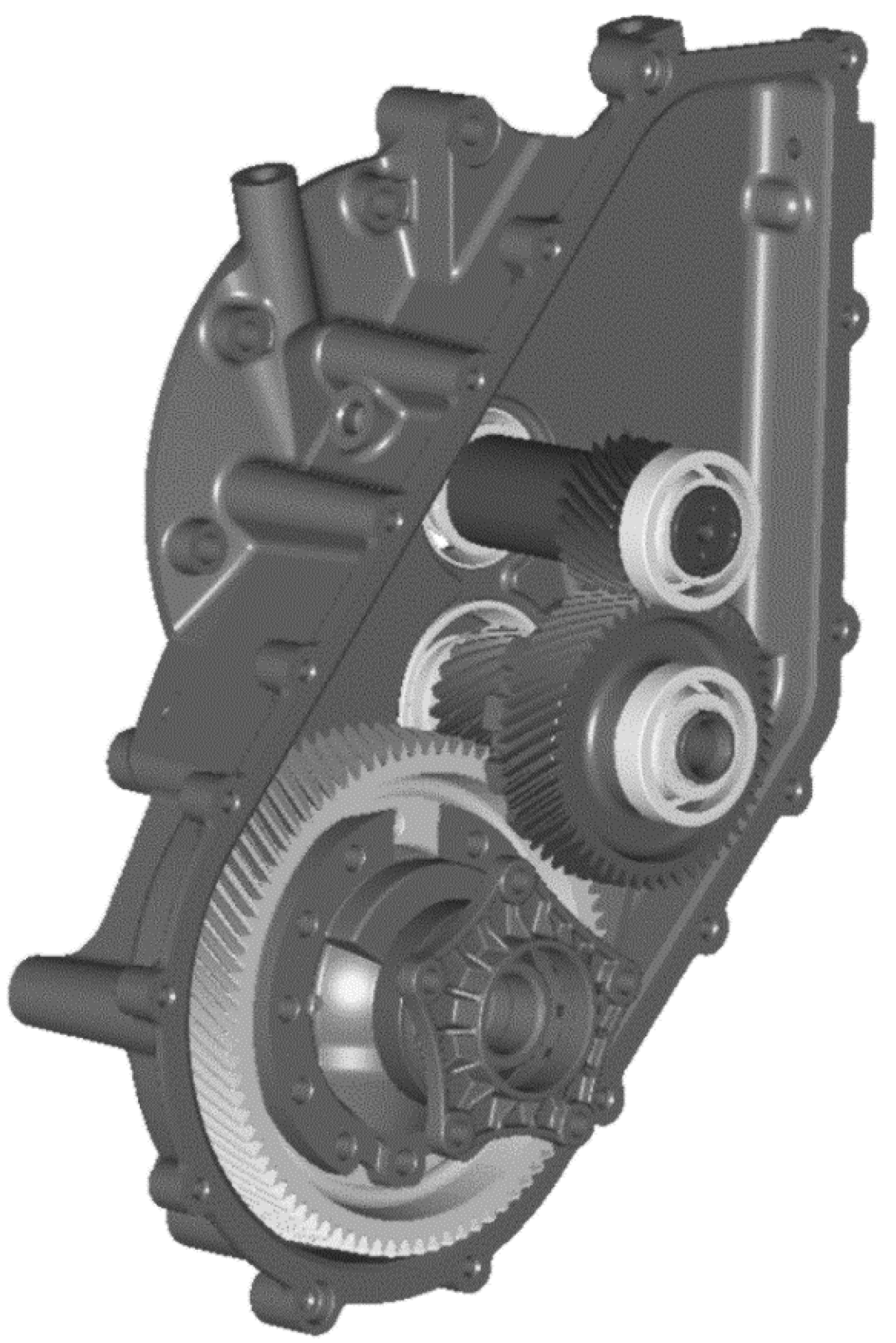
Most EVs use only reduction gears – a sort of one-speed EV reduction transmission/transaxle (see
Figure 1).
Luxury models, such as Porsche Taycan, Audi e-tron GT and BMW i8 use 2-speed e-drives developed by ZF. The 2-speed e-drive improves the range and driving characteristics since it allows one to achieve both high initial torque and top speed. Quite recently, a three-speed ZF transmission for passenger cars has been presented. In heavy-duty EVs, four speed transmissions are already in use.
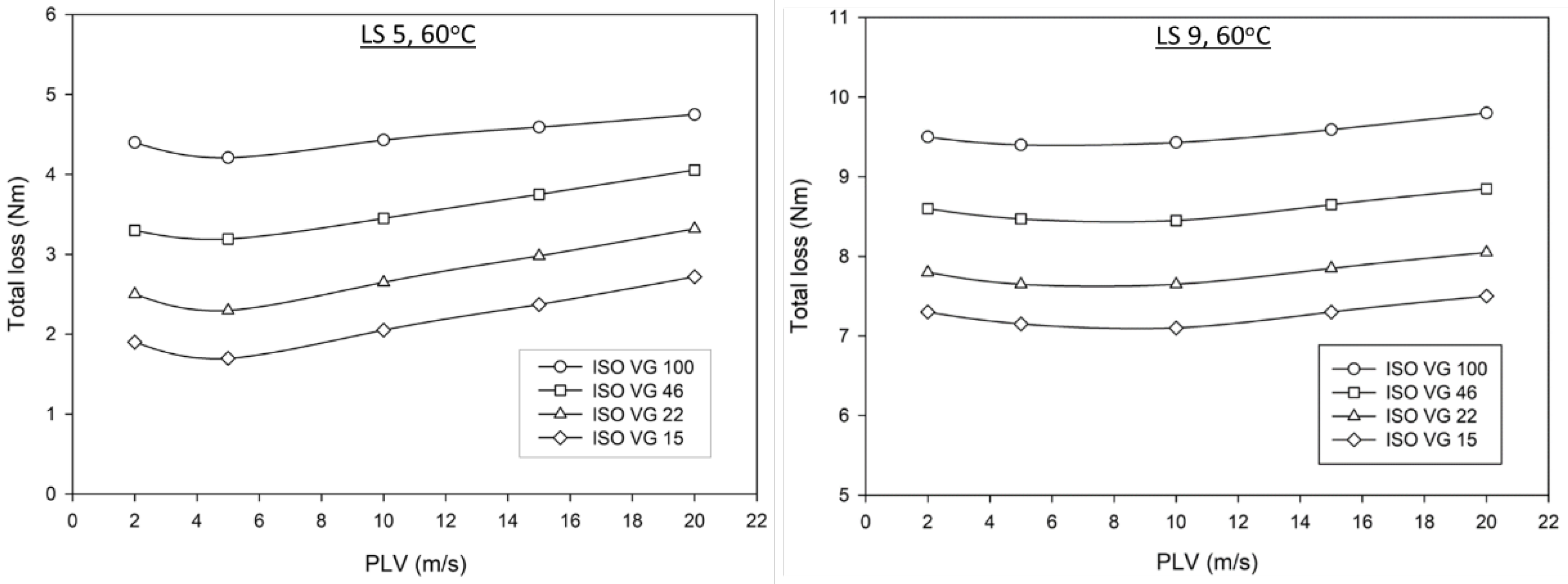
Proper gear lubrication is critical for transmission operation. Lubricant viscosity is the first parameter to look at. Industry standards such as ISO 6336 and AGMA 6011 provide recommendations for selecting the right viscosity grade depending on application. A higher gear speed favors the use of lower viscosity lubricants.
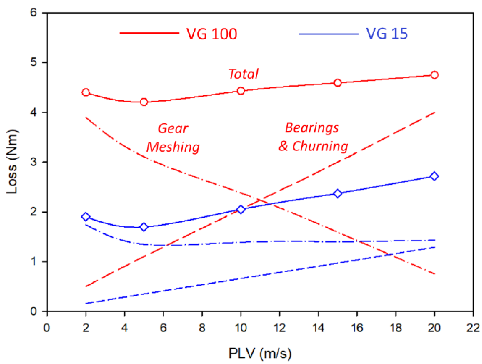
At the moment, automatic transmission fluids (ATFs) are commonly used in EV reduction transmissions, despite the fact that, design-wise, EV transmissions are quite different. Common ATFs such as MERCON® LV, DEXRON® VI, Toyota T4, Honda DW-1, etc have KV100 in the range 6 to 8 cSt. This roughly corresponds to the SAE J306 viscosity grades 70-75. Ultralow viscosity (ULV) ATFs go down to KV100 3.5 cSt are formulated using synthetic base oils, such as poly alpha olefins (PAO), esters and oil-soluble polyalkylene glycols (OSP). The market demand for ULV ATFs has been very low so far. At the same time, viscosity wise, ULV ATFs are a better fit for high-speed EV reduction transmissions. Cooling and resistance to shocks can be further improved by using forced lubrication. While sufficient lubrication is essential, excessive lubricant flow can lead to excessive heat generation and power losses, especially for high-speed gears. Hence, a total system approach is important – the gearbox and gear oil should fit together.
Proper selection of fluids for EV transmissions is complicated by a wide diversity of EV hardware. In general, EV transmission fluids call for a different spectrum of properties compared to conventional ATFs [
5,
6,
7]. Some properties are universally important for both: efficiency, durability, seal compatibility, foaming tendency, wide operating range, environment, health and safety (EHS) profile. Some other properties such as oxidation stability, copper corrosion and electrical conductivity gain increased significance.
Though the vast majority of EV transmission fluids in today’s use are formulated using API Group II and III base oils, synthetic products using PAO, esters and oil-soluble PAGs are gradually gaining momentum, in particular in ULV grades. There are also a number of novel non-conventional fluids in the research-in-progress phase, including water-PAG systems and ionic fluids, the use of which allows one to achieve ultralow viscosities, KV100 < 3 cSt, while improving heat transfer and electrical conductivity.
Many new additive types are coming into use as well. For instance, conventional sulfurized olefins, which are known to be copper-corrosive, are replaced by less corrosive hindered dialkyl polysulfides, thiophosphoric esters, aminophosphates and borates. The latter allow to achieve high scuffing resistance at low treat levels, while minimizing chemical polishing. Also, yellow metal deactivators such as benzotriazole are often used to reduce the risk of printed circuit board (PCB) corrosion. Disappearance of the clutch slippage problem opens the door to broader use of various friction modifiers for improved energy efficiency. New antioxidant types are also used, either alongside or instead of good old ZDDP. Finally, new shear-stable viscosity index improvers should be mentioned.
When it comes to improving gear tribology specifically for electric vehicles, everything basically boils down to proper gear design and geometric optimization, which includes selecting right materials and methods for gear manufacture and post-processing [
8,
9,
10].
In practice, we can never get perfect gears – good enough is the best. Gear accuracy is regulated by ISO 1328 and numerous national standards. To give the reader some feeling of numbers: For the gear diameter from 50 to 200 mm found in transmissions, the highest ISO 1328 accuracy grade sets tolerances down to a micron level, which is comparable to the thermal expansion effects. Such gears are very expensive to manufacture. The medium accuracy grades common for automotive applications set tolerances within 10 to 20 microns. The adequate accuracy for gears used in electric vehicles is around ISO 1328 Grade 6, but high-speed gears rated for speeds over 20,000 rpm have higher quality requirements. There is always a limit on how accurate you want to go to stay economical.
A good fit of gears in the gearbox is equally important [
8]. The typical backlash, i.e. the gap in between meshed gear teeth, in the final assembly is usually around 0.1-0.2 mm. Specifying a lower backlash value improves noise characteristics but it puts higher requirements on gear and assembly quality and compromises adaptivity to dynamic distortions.
Some minor surface imperfections can be remedied during the running-in stage. By using gear oil with adequate viscosity and high content of sulfur, one can design workable solutions even for low quality gears. Sulfurized additives help prevent scuffing and provides chemical polishing. Unfortunately, such oils are not suitable for electrified gearboxes because of copper corrosivity. On the other hand, by investing into better gear quality, one can minimize dependency of anti-scuff additives.
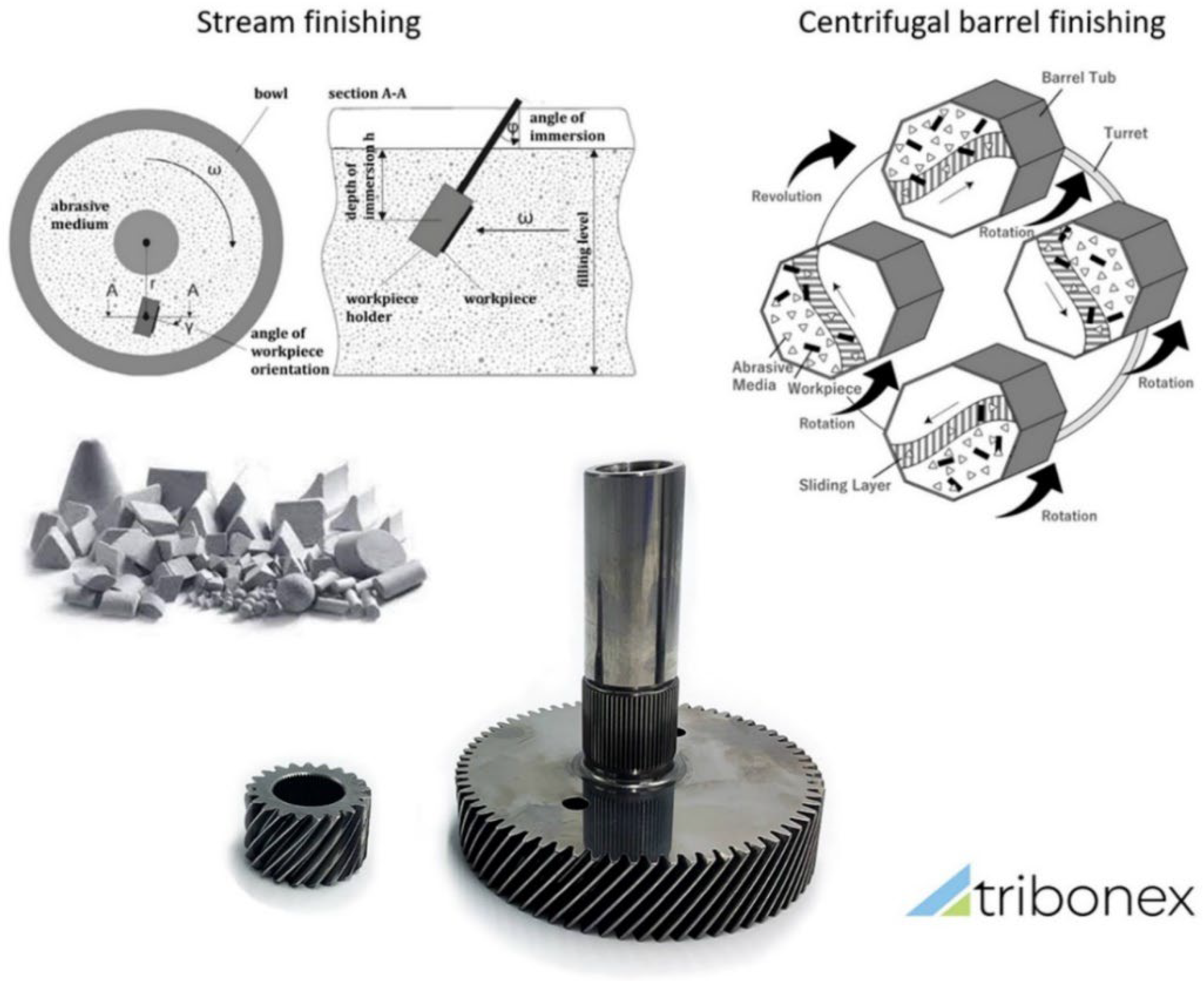
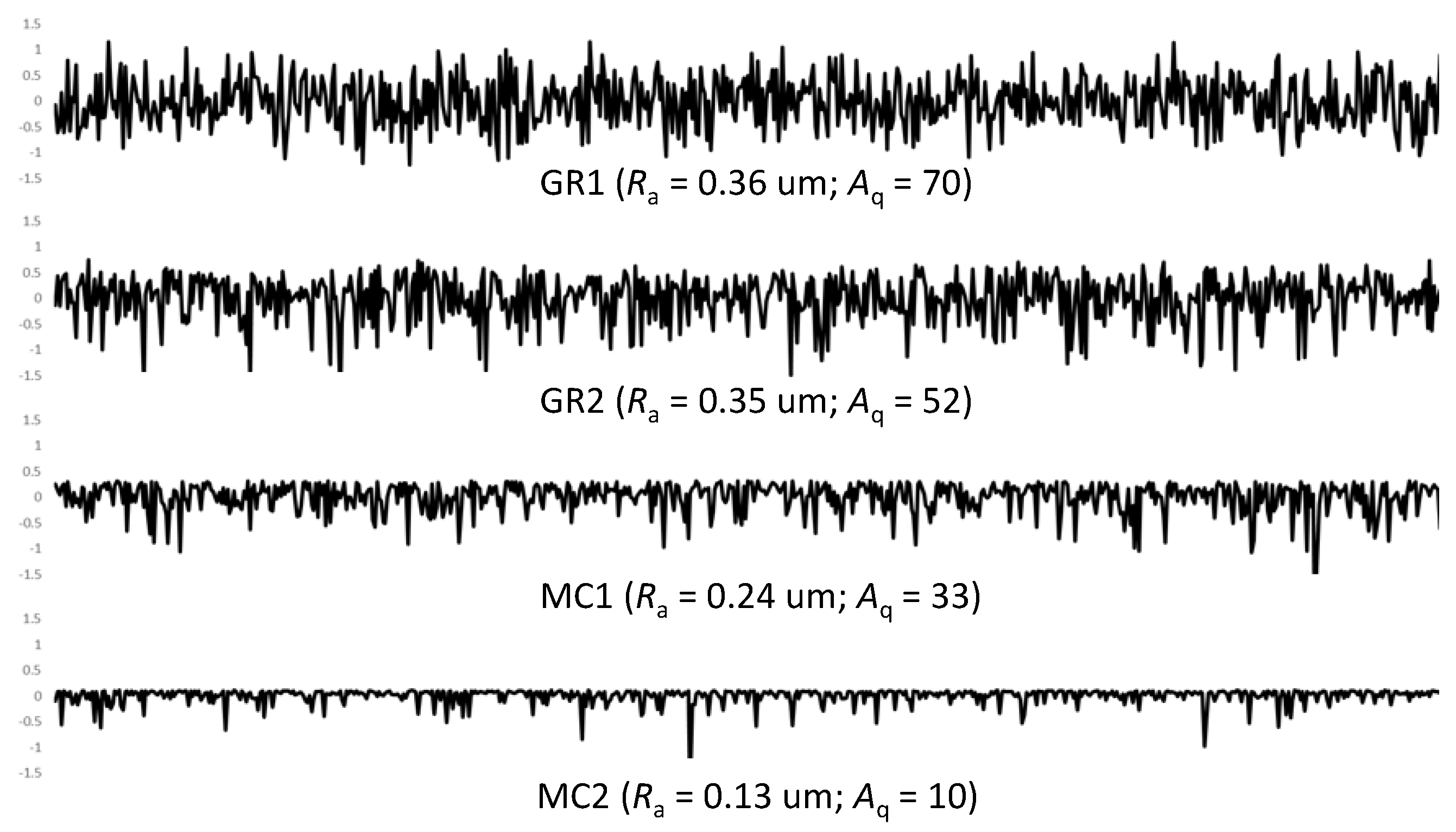
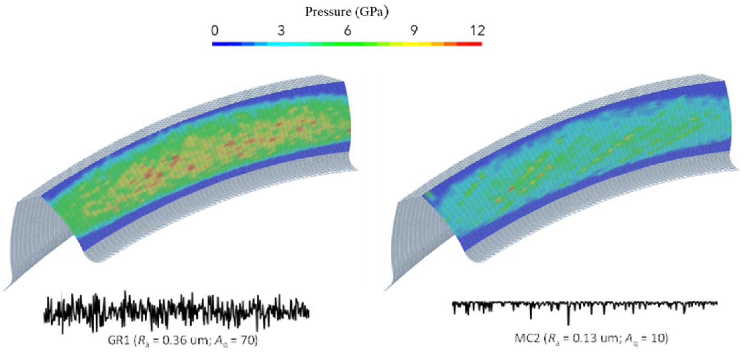
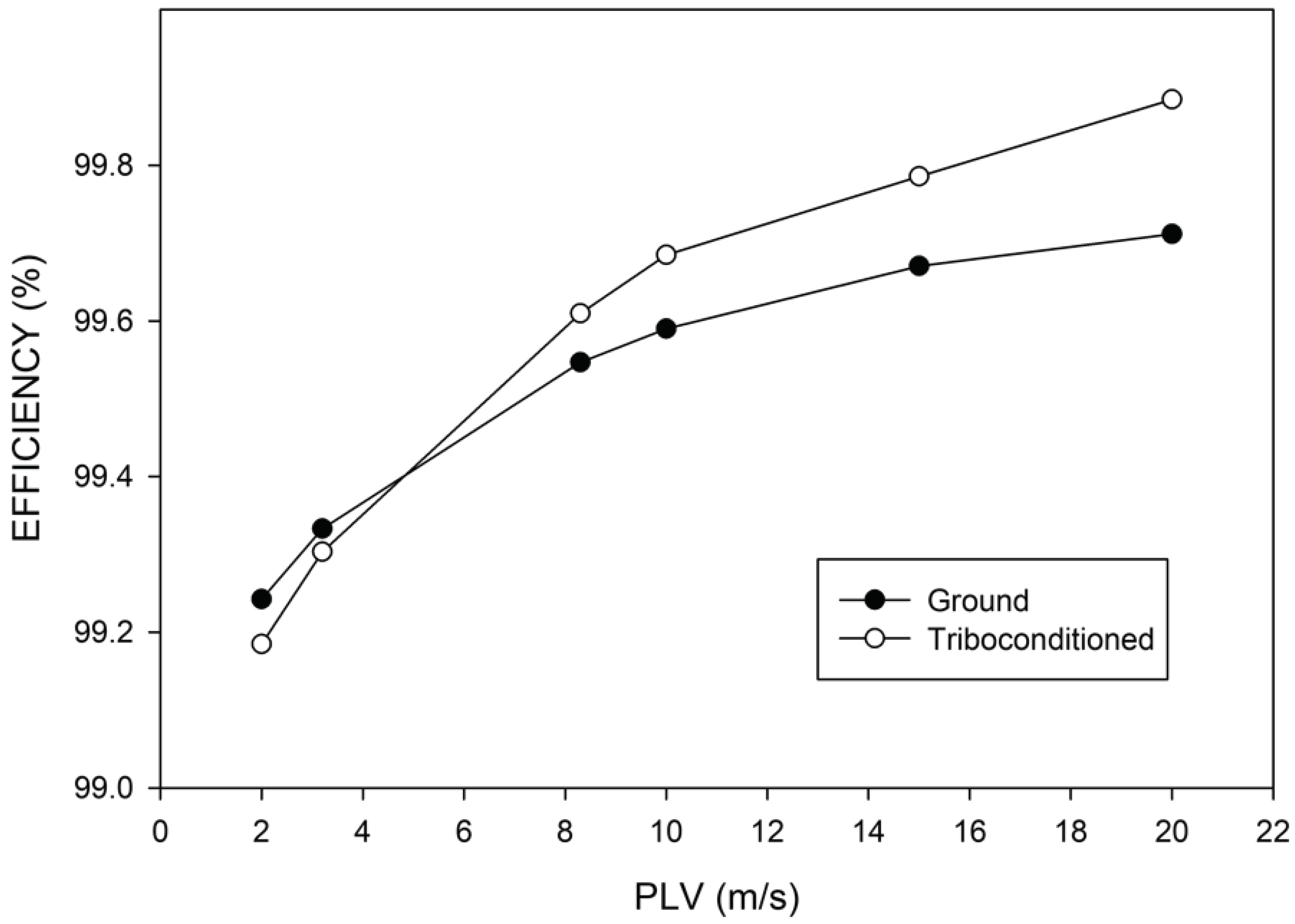
Assuming that gears have been machined with desired accuracy – which is normally accomplished by conventional grinding – additional surface finishing techniques can be applied in order to further optimize the surface roughness and waviness profiles. These include a variety of abrasive and non-abrasive processes, such as shaving, lapping, honing, abrasive flow machining, turbo-abrasive machining, stream finishing, accelerated surface finishing, electropolishing, burnishing, etc. Recently developed mechanochemical surface finishing methods such as Triboconditioning® CG (see
Figure 2) can be used as the final finishing operation bringing about a triad of effects: (i) surface roughness profile optimization, (ii) compressive stress buildup, and (iii) tribofilm priming, which greatly improves the tribological and NVH behavior of gears [
11,
12,
13].
2. Experimental
An FZG back-to-back gear test rig with FZG type A gears was used for scuffing resistance evaluation according to the standard ASTM D5182 procedure (A/8.3/90). The low-speed wear was evaluated according to ASTM D4998.
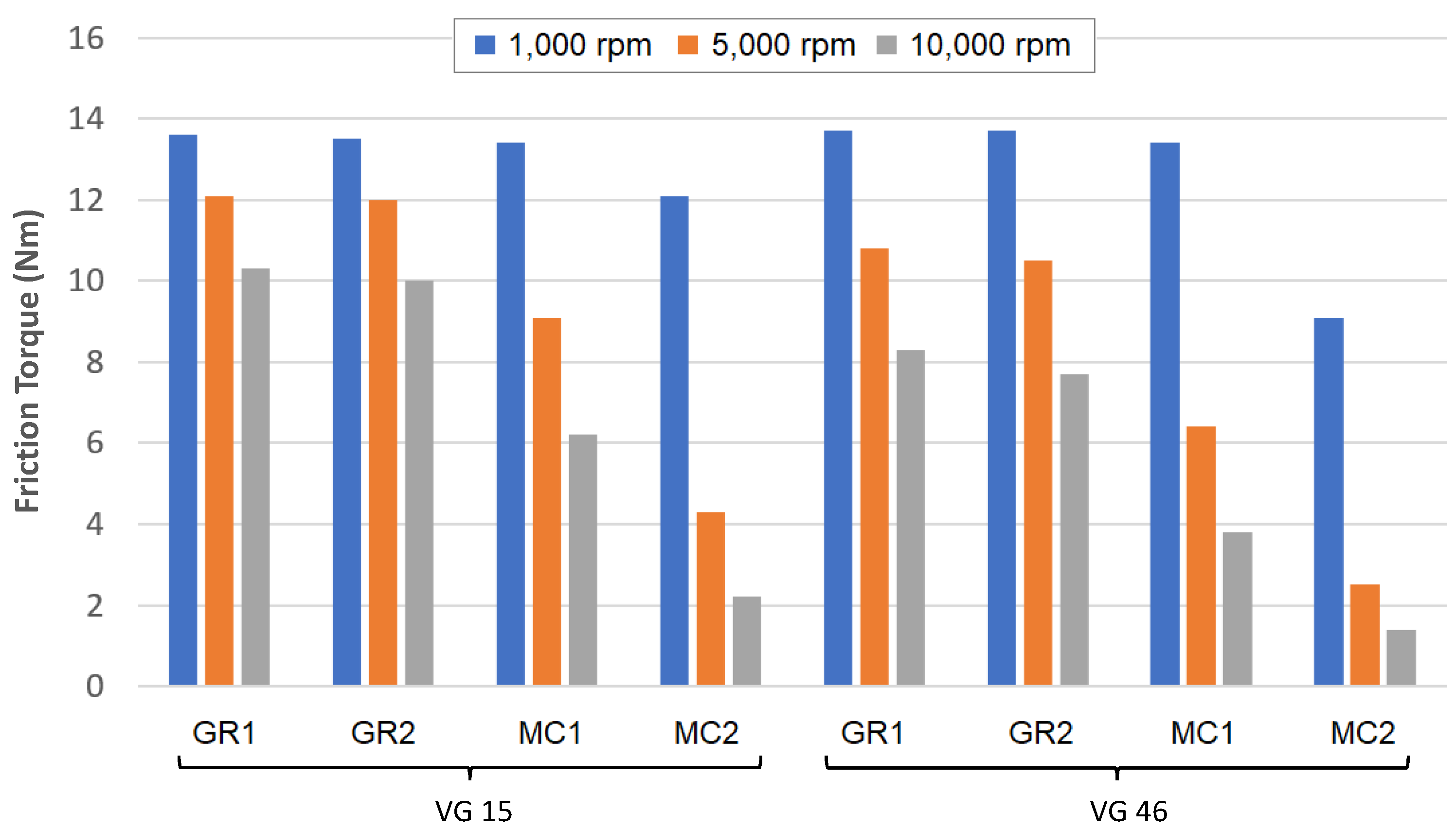
An FZG back-to-back gear test rig with FZG type C gears with tip relief was used for evaluation of different gear oils following the standard procedure [
14,
15,
16], except that the run-in and testing load stages were adjusted to ensure free-of-scuffing operation. The oil temperature was 60oC, deemed representative for electric driveline fluids under normal operation [
17]. A helical gear setup as described in ref.[
18] would be a better option for emulating the reduction gear operation, but unfortunately, it was not available. To evaluate the effect of mechanochemical surface finishing, one set of gears was additionally processed applying the Triboconditioning® CG method.
Gear oils were blended by using a mixture of API Group II 600N and PAO3.5. A commercial ATF additive package was used with the same treat level for all four viscosity grades. Using the identical additive package and common base eliminates uncertainties related to differences in additive activity and base oil properties.
Table 1.
The properties of gear oils.
Table 1.
The properties of gear oils.
| Viscosity grade |
KV40, cSt |
KV100, cSt |
Density, RT, g cm-3 |
| ISO VG 100 |
98.1 |
11.2 |
0.87 |
| ISO VG 46 |
46.2 |
7.0 |
0.85 |
| ISO VG 22 |
23.4 |
5.0 |
0.83 |
| ISO VG 15 |
14.5 |
3.5 |
0.82 |
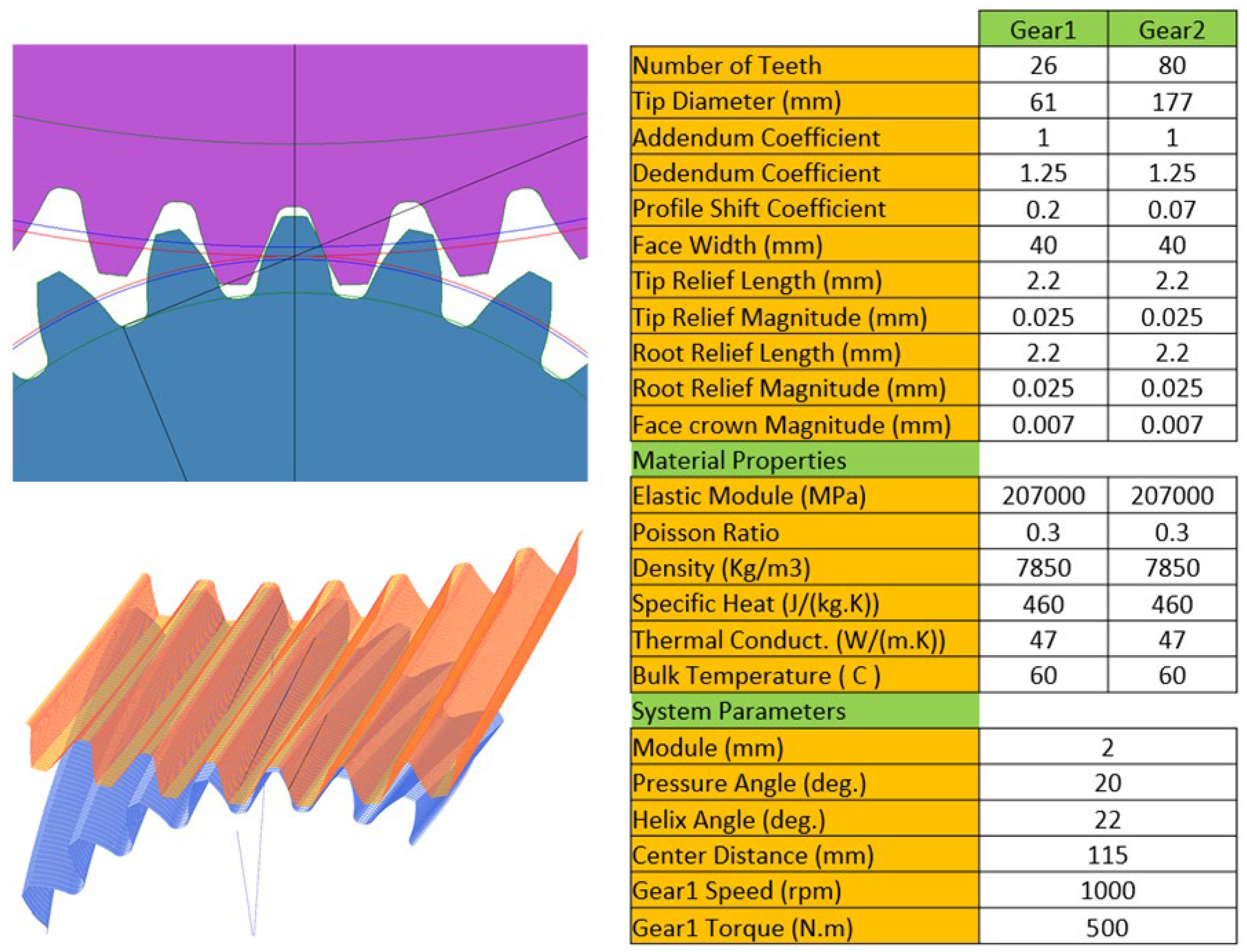
Gear tribology simulations were carried out using a thermal elastohydrodynamic (TEHD) lubrication model as described in ref.[
19]. The EHD film thickness was calculated using the Najjari-Guilbault method [
20].
The surface of gears was characterized using using a Form Talysurf Intra stylus-type surface metrology system and an Optosurf OS500 scattered light system. The scattered light method [
21,
22] is based on a mirror facet model of the surface (also known as the Kirchhoff or tangent plane approximation [
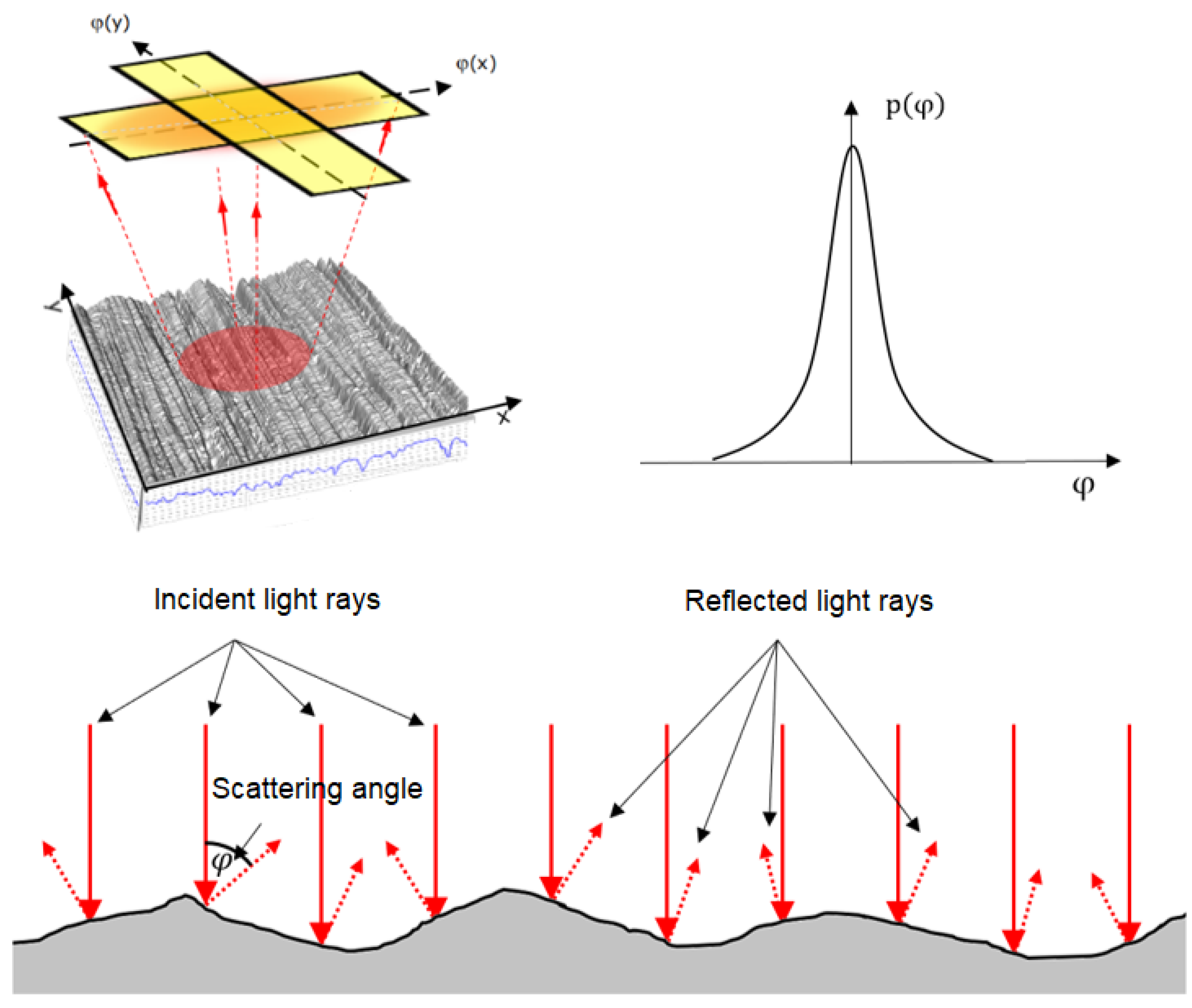
23]) and hence is best suited for the analysis of sufficiently smooth and highly reflective surfaces. When the incident light beam hits the surface, the individual light rays are reflected at the micro facets in directions determined by the individual facet orientation. As a result, the reflected specular beam broadens. This phenomenon is known as diffuse scattering. The backscattered light is transmitted to a focal plane by means of Fourier optics. The detected intensity distribution corresponds to the frequency distribution of the scattering angles, as explained in
Figure 3.
The variance of the angular distribution,
Aq, of scattered light relates to the scattering angle,
ϕ, as
where
k is a normalization factor,
p(
φ) is the intensity,
n is the total number of points measured, and the bar denotes the average value. Hence,
Aq can be determined directly from the scattered light measurements.
In general, there is no way to retrieve any conventional amplitude roughness parameters (defined by ISO 4287) from Aq measurements, nor is it possible to calculate Aq from the amplitude roughness parameters for an arbitrary surface roughness profile. However, some useful correlations can be found for random rough surfaces with a Gaussian height distribution. Since Aq is a measure of the gradient roughness, one would expect a correlation between Aq and the root mean square slope, Aq ~ RΔq2. The latter can be approximated by Ra/Sm where Ra is the roughness average and Sm is the mean spacing of profile irregularities. This means that if Ra is reduced without changing Sm, Aq is going to decrease. This makes light scattering ideal for the inspection of optically smooth surfaces.

