1. Introduction
The Earth’s gravity field influences physical and chemical processes through buoyancy, convection, and sedimentation. [
1]. Under generated stress, even cells react and respond to mechanical stimulus [
2]. Under the influence of mechanical forces, tissues evolve and expand in response to variations in forces around it. The regulation of cellular processes, including protein synthesis, cell proliferation and cell death, are fundamentally influenced by mechanical forces [
3,
4].The applied mechanical forces act at the interface between cells and the extracellular matrix (ECM) tend to change its physical properties by affecting cell behavior and its structure. For example, the perturbation includes local structural variation in adhesion sites, modification of cell motility, propagation, and lifespan [
5,
6].
Furthermore, during space travel, microgravity has an impact on human organs. The cardiovascular changes brought about by entering micro-gravity puts in more intricate acclimatisation process, as seen by a
decrease in plasma volume and a drop in erythropoietin secretion. As a result, the mass of red blood cells decreases [
7,
8].The microgravity effect induces muscle loss accompanied by a loss of force-generating myofilaments as energy intake is reduced due to the microgravitation force [
9,
10]. To gain more insight into how biological processes are impacted by gravity, the two most popular and widely used technological platforms to simulate microgravity conditions on Earth are the clinostat and the Random Positioning Machine (RPM). Fluid motion inside the system is more rapid than the rate at which it responds to the force of gravity, random rotation will modify the orientation of objects relative to the gravity vector and produce weightlessness circumstances [
11,
12,
13].
The random positioning machine (RPM) works by minimizing gravity vectors to zero. The RPM consists of two frames mounted on a gimbal, each rotating on its own axis with its own motor. The designated algorithm in the RPM periodically inverts the fluid’s circulation direction. The periodic redirection ensures the gravity vector to dispersed in all directions over time. Thus, allowing the sample gravity vector averaged over time to converge towards zero. The RPM frame of rotation should be more responsive than the biological process investigated without exceeding the centrifugal forces underlying the system, allowing the gravity vector to change direction on a continuous basis. This shift in orientation forces the cells to forfeit their perception of direction and enter a state of microgravity [
12,
14,
15].
From this point on, literature’s seldom addressed a thorough grasp of the fluid’s motion in a cell culture flask, its complex behaviour, and potential effects on the cells. Such analyses are crucial for understanding the flow field and the loading stresses on cells when interpreting biological data. To this end, a high-fidelity computational study is modeled to capture this complex flow field inside the cell culture flask placed within the RPM. For the sake of aptness, in the fluid dynamic simulation, the geometrical model is allowed to rotate in the x and y axes. Furthermore, cells grown in a flat plane were used for most of the simulations used to study how microgravity affects the human immune system. The present study address the aspect of three-dimensional space cell culture models as a precise in
vitro system that is relevant to both physiological and pathological aspects under
g conditions in RPM. Such numerical validations are cost-effective when evaluating biological experiments adopting RPM as a microgravity simulation tool. To achieve this goal, the remainder of the paper is organized as follows.
Section 2 details the governing methods applied to solve fluid flow within the system.
Section 3 presents a detailed analysis to validate the model and evaluates the nature of flow inside a cell culture flask for free flow and in a porous medium distribution.
2. Governing Equations, geometry, and solver
settings
2.1. Governing equations
The flow field inside a confined medium is solved using the incompressible Navier Stokes equation, which constitutes both continuity and momentum equation expressed as [
16]
Where the normalized pressure field, the velocity field, the kinematic viscosity of the medium, t the time and the turbulence viscosity.
The 3D collagen matrix is modeled as a porous medium and added as a source term in the governing equation. The porous media inside the flask is represented by enumerating the Darcy Forchheimer equation in the momentum equation as a source term, and is derived as:
The source term
constitute a viscous loss term and an inertial loss term, formulating a pressure drop
Where the coefficients
D and
F are the Darcy contribution and the Forchheimer contribution. A detailed explanation of adding porous medium in OpenFOAM® simulation can be viewed in [
17]
2.1.1. Turbulence modeling
A transition turbulence model (
) is selected to model the swirl and uncertainty flow characteristic inside the flask with the porous medium. The
model is one of the best fits for the Low-Reynolds phenomenon with flexibility and accuracy [
18,
19]. The
is a two-equation eddy-viscosity model with a combination of both
and
models.
Energy in turbulence
k is given by
The effective turbulent viscosity and the Peclet number are given by
The closure constants are determined as and is 2.0, while Re is the Reynolds number.
2.1.2. Rigid body dynamics
The RPM rotates along two orthogonal axes to alter their orientation in space, thus eliminating the effect of gravity. The dedicated sample is pointed to rotate both on the vertical and horizontal axes. Based on the specific RPM model, the categorization of the gravity vector deviates in the flask. For the present study, the frame is fixed to rotate at a constant speed and analogously transposes the rotation direction at arbitrary positions with time [
20][
13]. Acknowledging the above postulates, for a more simplified case study the RPM’s frame of rotation is fixed to the x and y-axis.
Therefore, the governing equation for the RPM rotation is given by
Where is the position vector, and are the rotation around the x and y-axis and angular velocity.
The dynamic mesh motion simulates the rotation in the two perpendicular axes (x and y) with respect to the displacement set in the rotation matrix. Therefore, the relative displacement of the mesh is calculated in each time step. Three distinct rotational velocities namely and were selected for the case study, which is assumed to be constant in the x and y-axis, wherein the gravity force is defined in the negative z-direction. Therefore, the acquired time step for each rotational velocities will be 0.0333s, 0.0222s, and 0.01666s.
2.2. Geometry and boundary conditions
From the experimental point of view, the biological samples saturated with cultivation medium are placed in a custom-made flask and allowed to constantly rotate on the RPM.
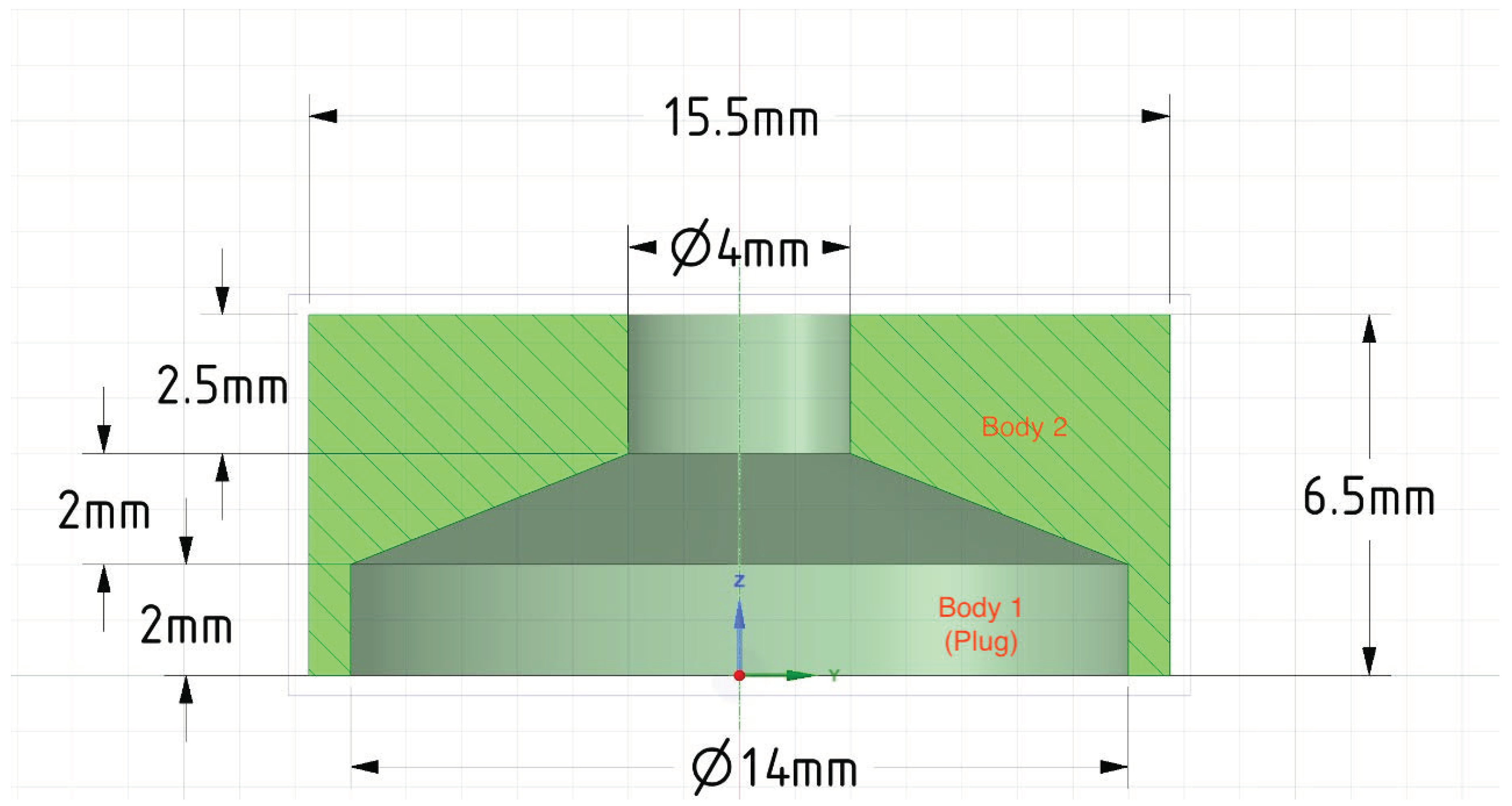
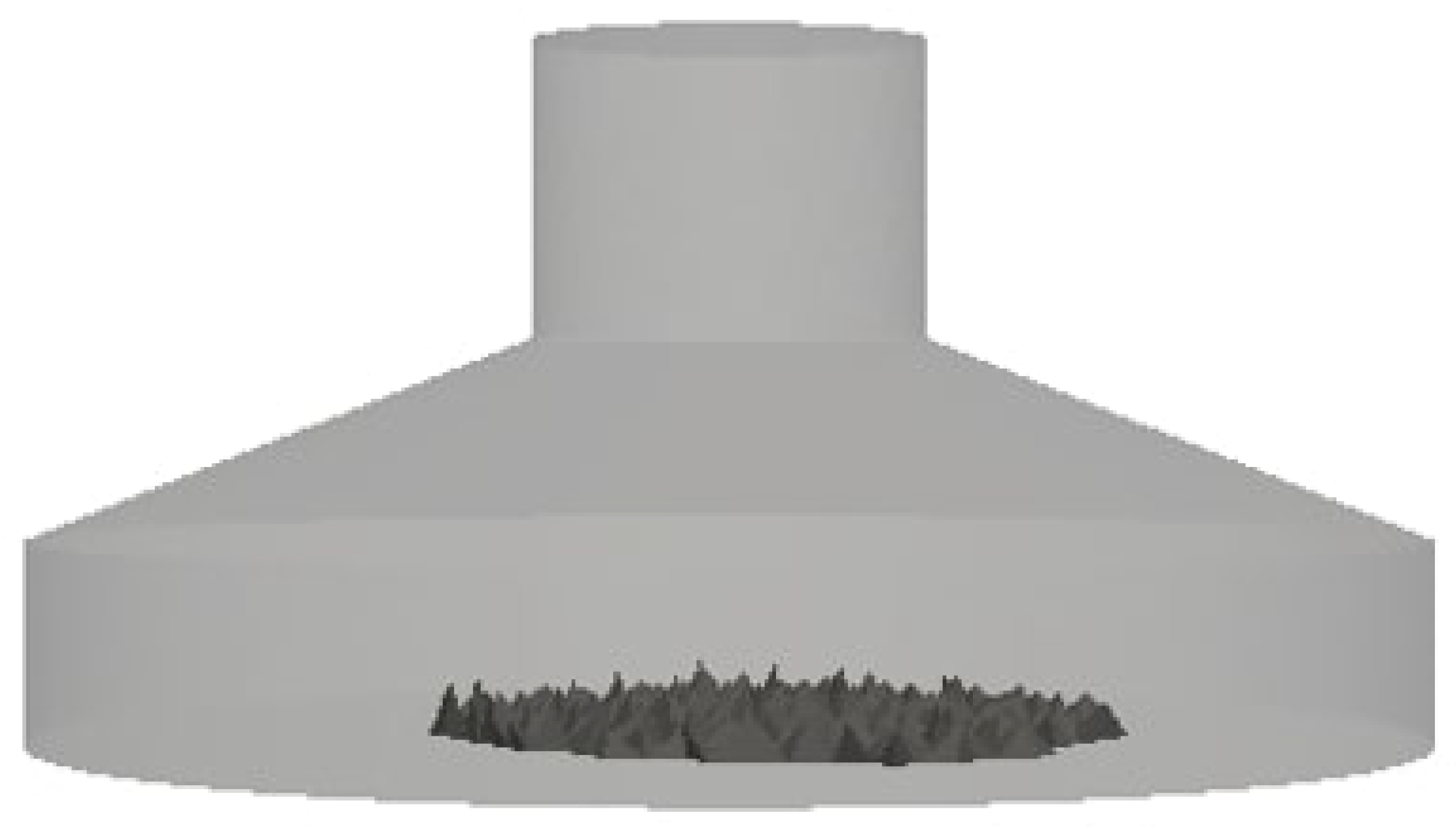
Figure 1 shows the schematic view of the adopted cylindrical flask [
21] with dimensions (mm) designed using the Gmsh 4.8.4 finite element mesh generator. For further simplification, the cultivation medium is deemed an aqueous solution representing water at
. The water density
and kinematic viscosity
is set to be 993.336
and
. The Reynolds number for the simulations is 70, 100, and 150, which agrees with rotational speeds of 30 deg/s, 45 deg/s, and 60 deg/s. The applied physical limits are presented in
Table 1
2.3. Mesh and solver settings
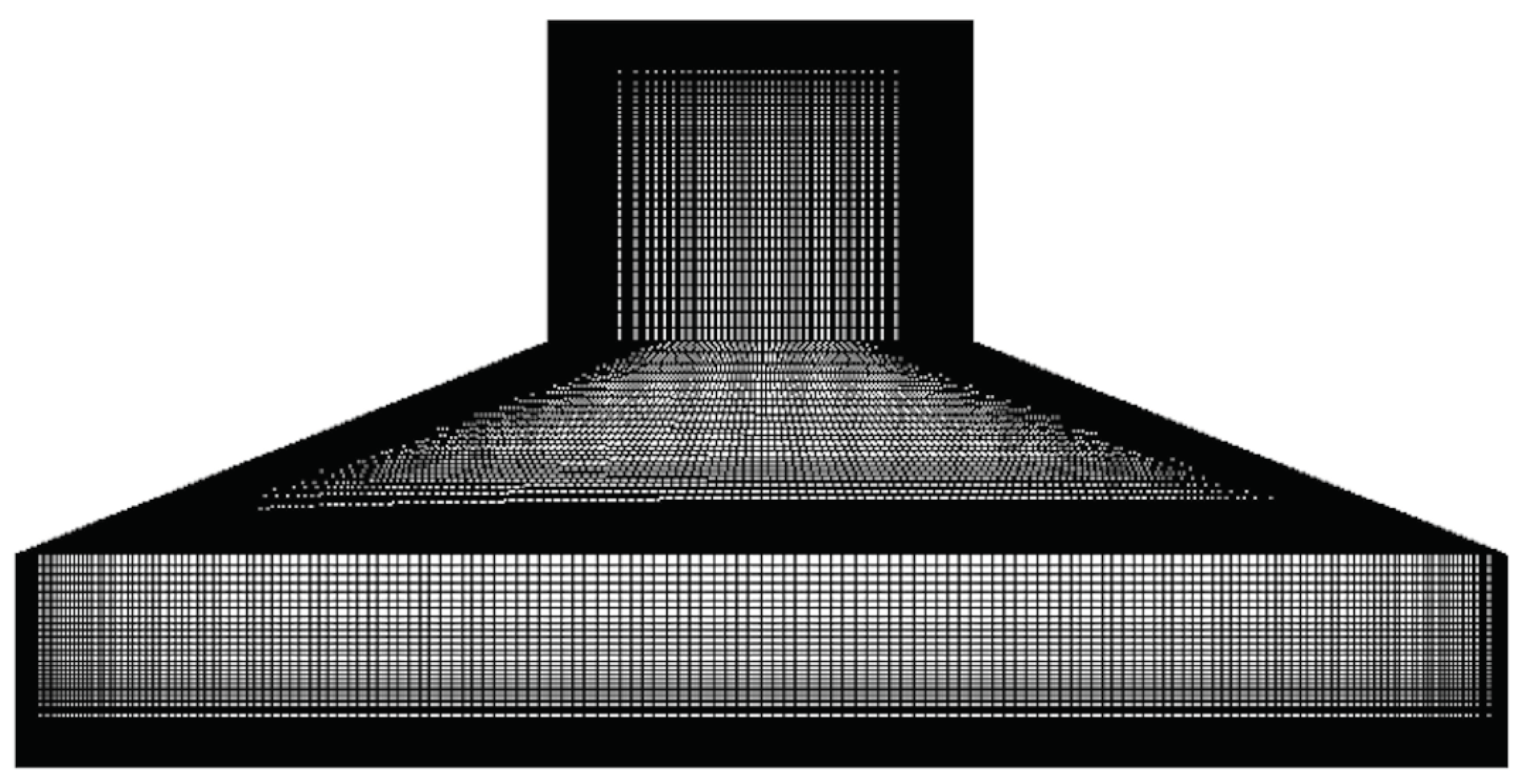
Due to the arched surface of the cylindrical flask, a tetrahedral mesh of about 2.48 million elements is generated using Gmsh as seen in
Figure 2. A fine refinement around the walls are made, and the first wall distance is measured to be 0.0004m for a desired dimensionless wall distance
of 0.5 and the corresponding mesh layer stretching is set to be 1.2. The designated refinement guarantees the boundary layer, accurately resolved core, and is typically recommended with
turbulence models. Hence the adopted mesh profile guides to a fine mesh composition around the flask geometry and assists in evading the grid dependency study. The discretization of the fluid equation is handled by the
OpenFOAM solver
pimpleFoam. An incompressible transient solver which permits dynamic mesh computation adopting
PIMPLE algorithm [
23]. The following discretization schemes are used for respective terms in the equations. The term of the time derivative
is discretized using a first-order implicit bounded Euler scheme. The gradient
of pressure and velocity fields is discretized using the second-order Gauss linear integration. The divergence
of velocity and turbulent properties were discretized using a second-order limited linear-upwind scheme with Gaussian integration. The Laplacian terms
are discretized with a second-order linear corrected scheme with Gaussian integration. In the current computation, rotation dynamics is performed adopting the
multiSolidBodyMotion solver.
3. Result and Discussion
To overcome the variation in the physical quantities of the radial forces within the cell culture flask, a small cylindrical cell culture flask with a minimal centrifuge radius is used [
21]. During the initialization of the solution, the motion of the fluid flow within the culture flask becomes random. At this limit, the relative velocity is low near the wall and, therefore, there is no shear force on the wall of the flask [
24]. At transient phase, the wall velocity will be on a higher side. For the RPM simulation, the samples are placed at the center of rotation to lessen centrifugal accelerations, and to mimic the combination of centrifugal and rotation, the specimen is set to rotate along the x- and y-axis.
3.1. Validation of the computational model
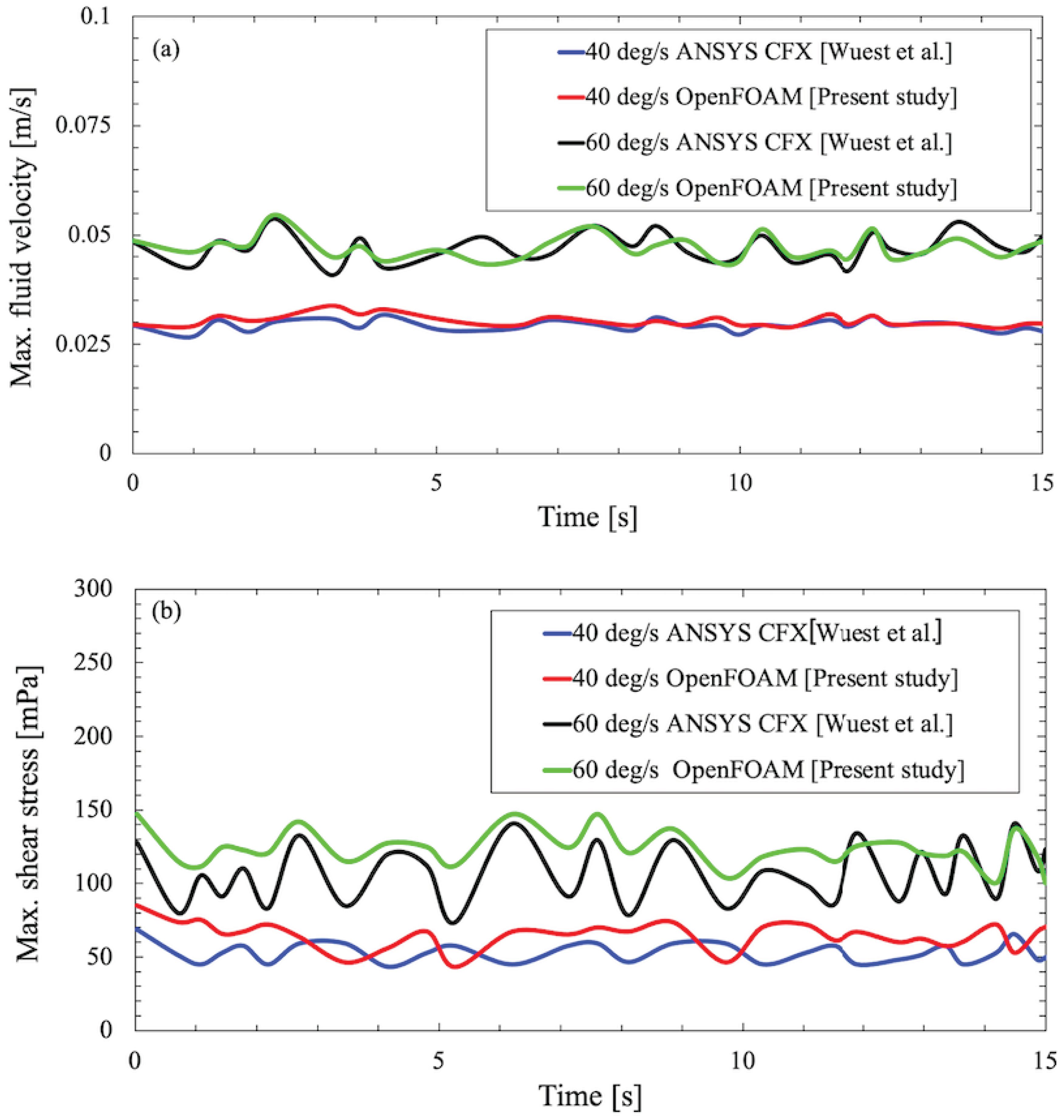
To favor the adopted CFD approach using OpenFoam solver and to ensure authenticity of the computed velocity and forces inside the flask, a validation study is performed against a benchmark numerical study conducted by Wuest et al. [
25]. The numerical study by Wuest et al. calibrated the velocity profile and shear stresses along the walls in the RPM using a rectangular cell culture flask similar to the shape of the commercially available T25 flask and simulated it using
ANSYS CFX 16.0(ANSYS, Inc.).
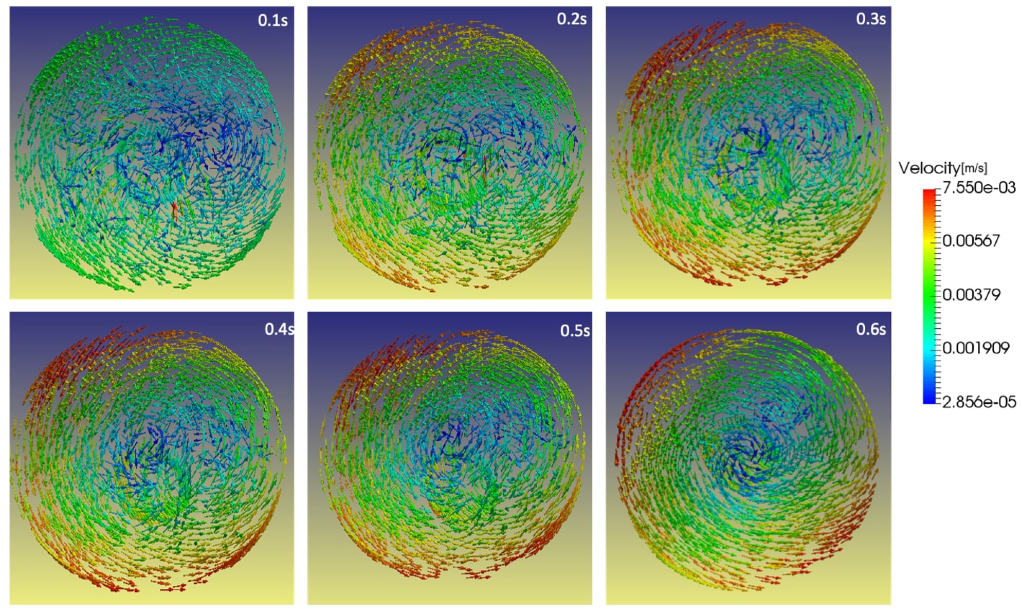
Figure 3 and
Figure 4 verifies that the results obtained using OpenFoam simulations are in excellent agreement with those computed by Wuest et al. and persist as a representative of the simulated phenomena.
3.2. Flask velocity field
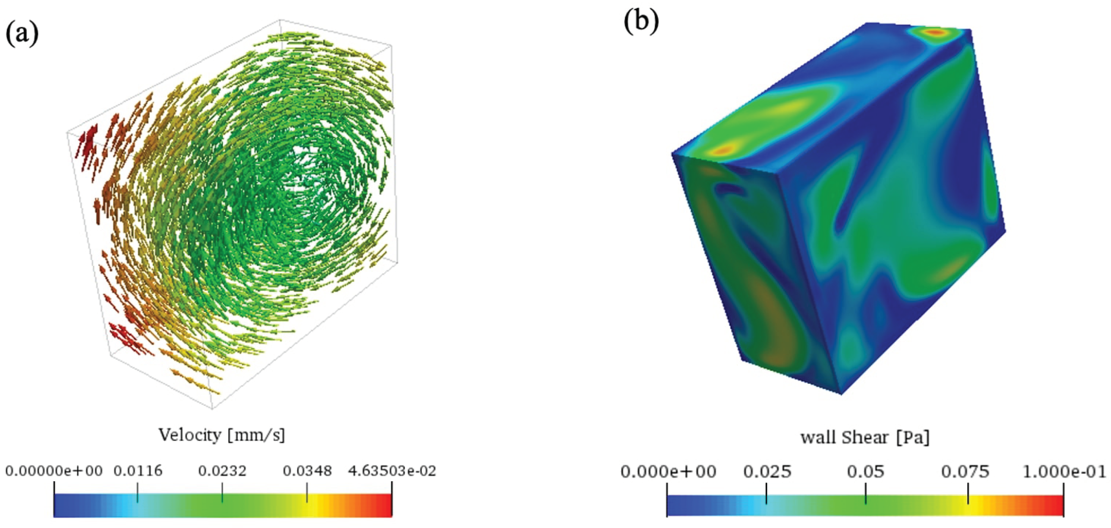
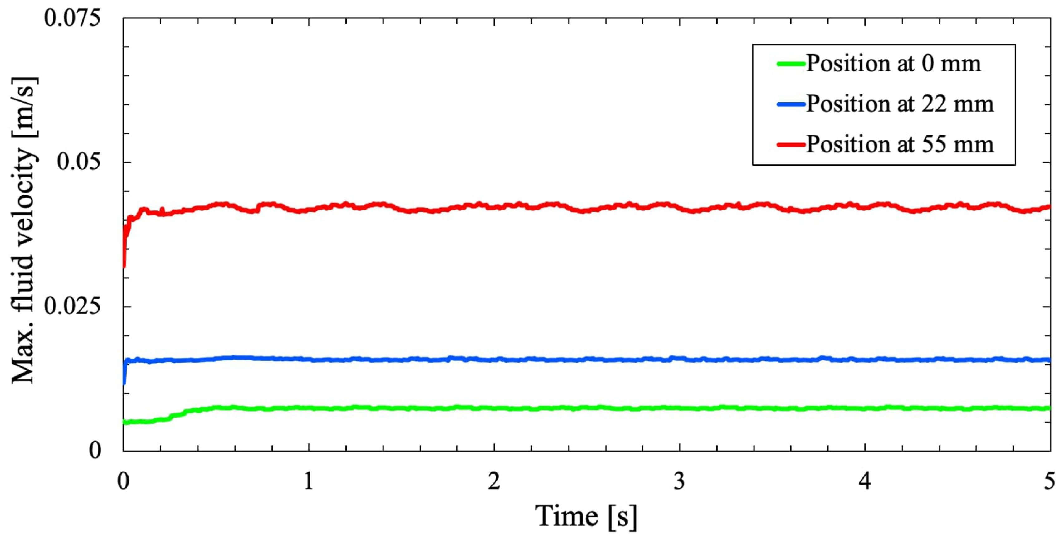
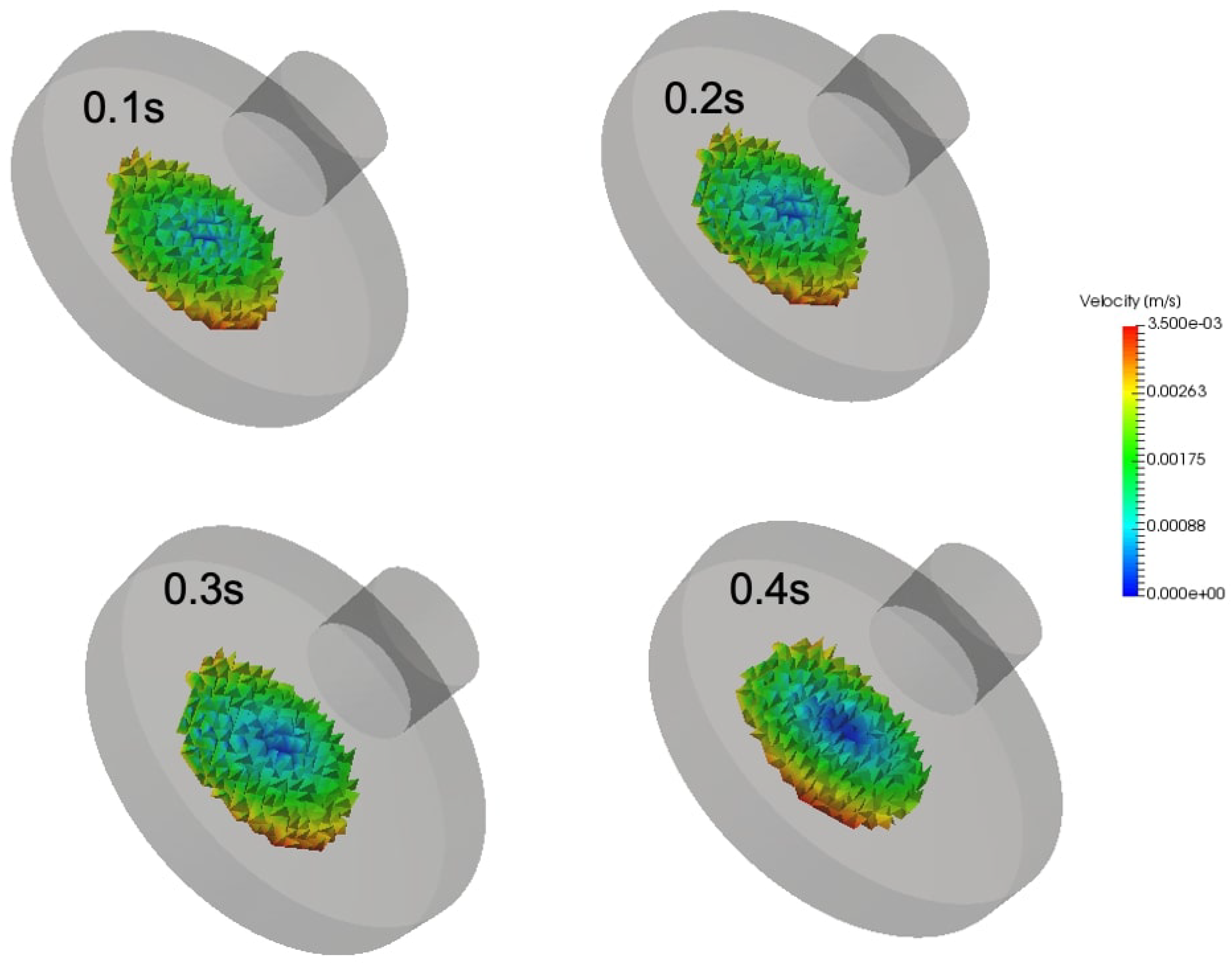
After successful validation, the objective is to determine the dynamic characterization of the fluid and the corresponding wall forces that occur inside a cylindrical cell culture flask with an RPM. Earlier study on RPM experiments recommends placing the samples near the center of rotation to depreciate centrifugal accelerations. This assists in avoiding differences in results due to centrifugal accelerations and further helps in reducing the solution space of the numerical simulations. Consequently, a numerical computation was conducted to show the variation in the field on the flask as a result of centrifugal accelerations. For this purpose, the preferred cylindrical cell culture flask is allowed to rotate around the x and y axes for an angular velocity,
of 60 deg/s.
Figure 5 shows the effect of centrifugal accelerations on the cell culture flask with a large variation as the distance increases.
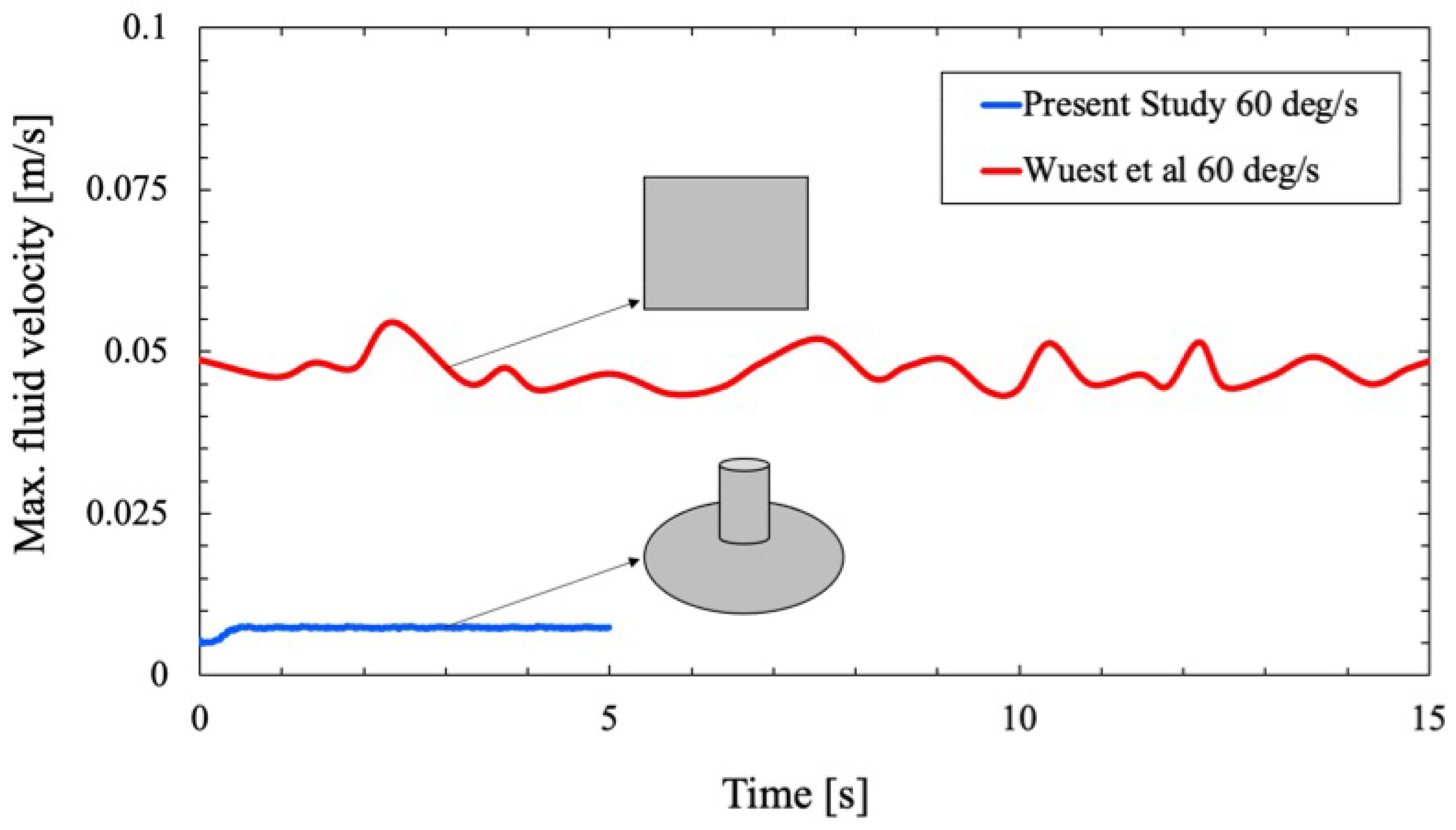
A comparison study is conducted to analyze the fluid motion within the cell culture flask in the RPM with that of Wuest et al. [
25].
Figure 6 shows the circulating fluid velocity field for a rectangular flask of Wuest et al. and the circular flask. Both simulations predict a random and fluctuating condition in the fluid velocity field within the flask, and the circulating fluid velocity never approaches a steady-state condition. The trend in the maximum velocity field for both flasks also remains identical with a non-linear pattern near the wall.
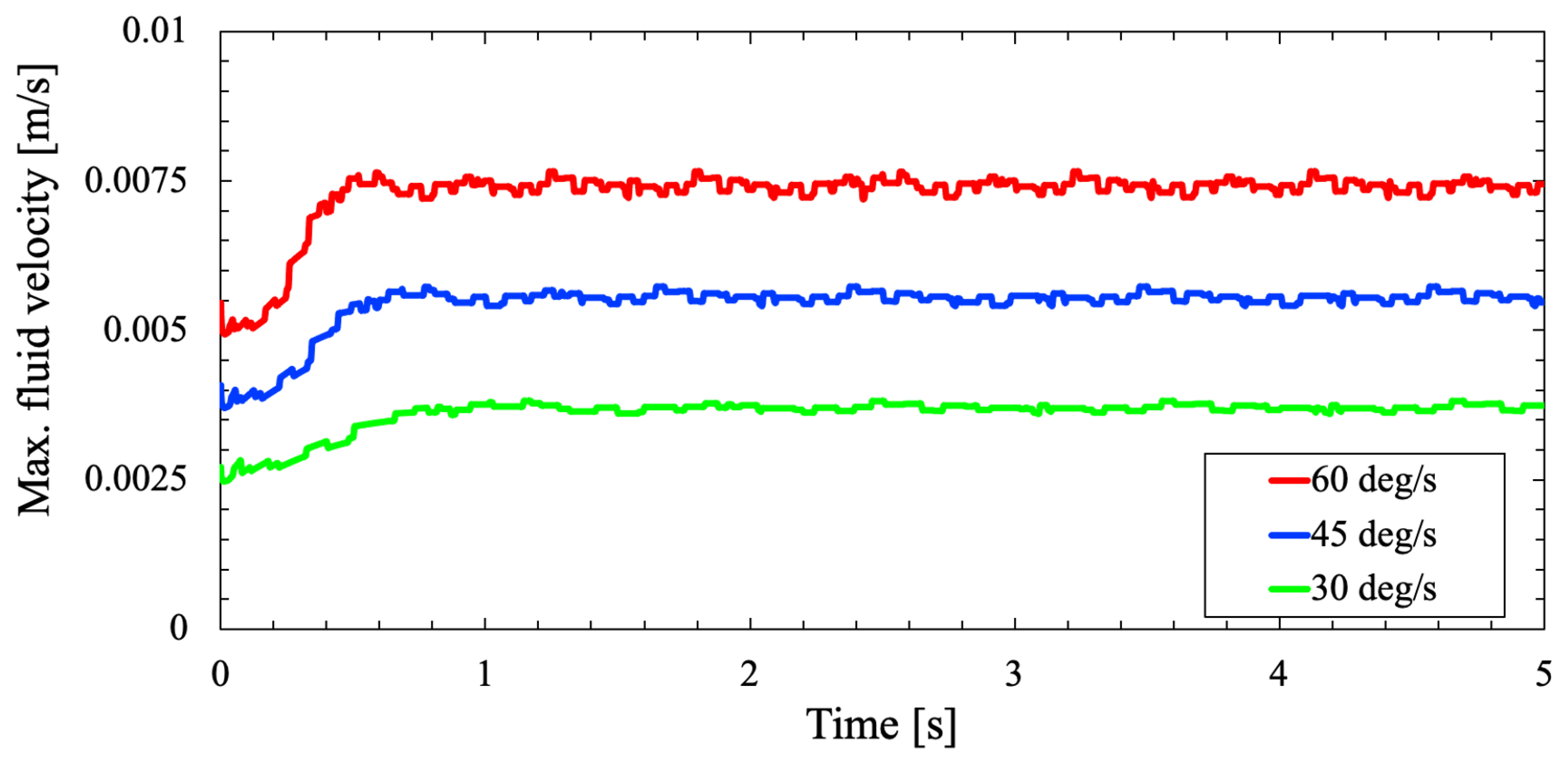
Furthermore, a comparative case study is made on the RPM for three different rotational velocities
and
to analyze the shear stresses on the flask wall due to varying RPM rotational velocity. From
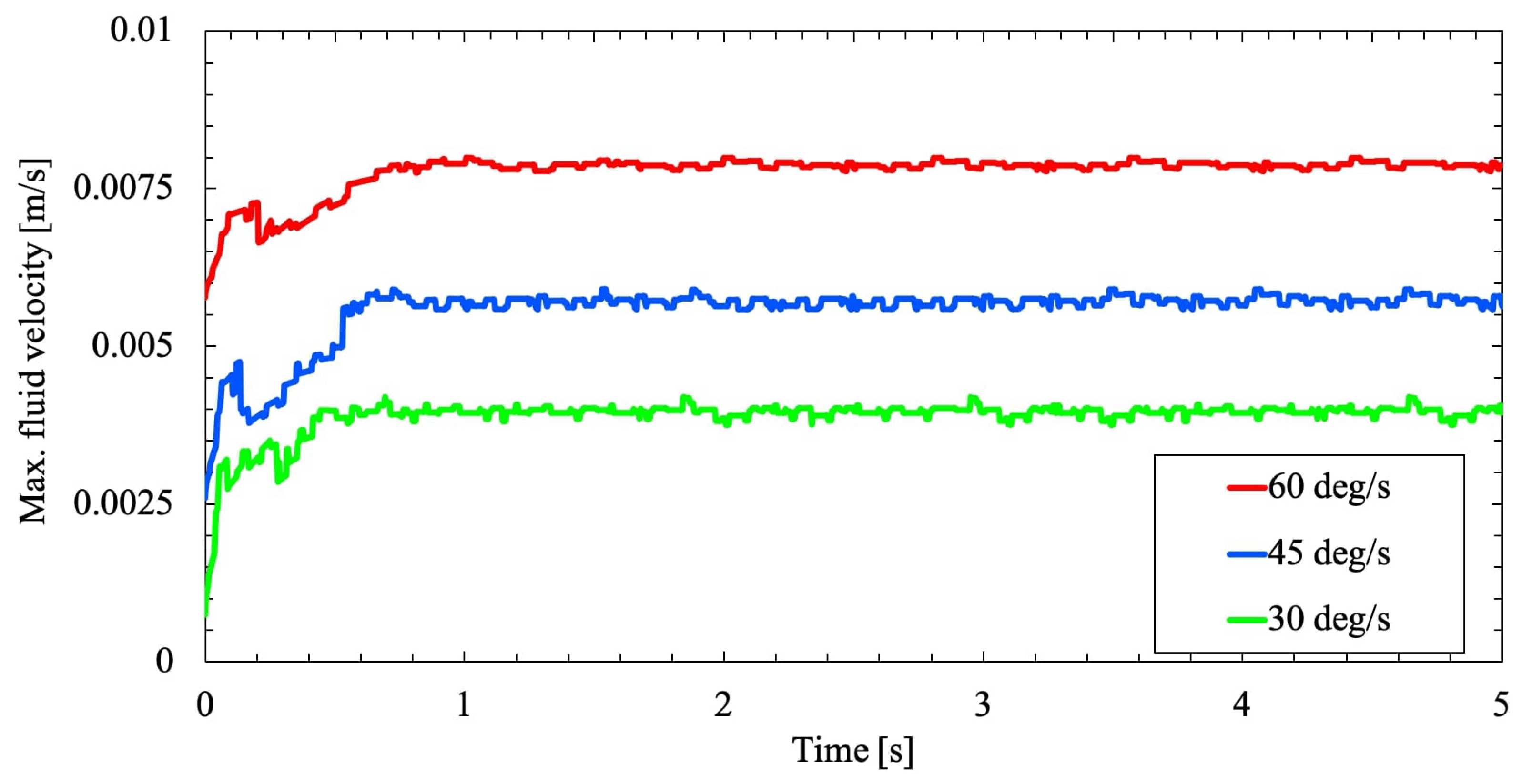
Figure 7 and
Figure 8, the fluid velocity in the flask due to the two-axis rotation never progressed to a steady-state condition. Variation with time, the velocity profile continues to be random and fluctuating. As the cell culture flask rotates on two axes, the fluid flow inside the flask is periodically inverted. Because when the fluid reaches the velocity of the flask, the flask will move to a new position. Henceforth, the fluid rotation will not match with the flask rotation and constantly get inverted to remain unsteady.
3.3. Porous medium study
The two-axis rotation of the RPM improves the gravity vector over time within the flask and impacts a local force on cell culture containment. Therefore, the addition of a porous medium within the cell culture might slightly impact the fluid shear stresses in the flask wall due to flow acceleration near the wall.
Figure 9 shows the addition of porous medium within the cell culture flask and is analyzed for three different rotational velocities
and
.
From
Figure 10 and
Figure 11 the velocity of the fluid inside the flask is slightly increased for the simulation with the porous medium seen in
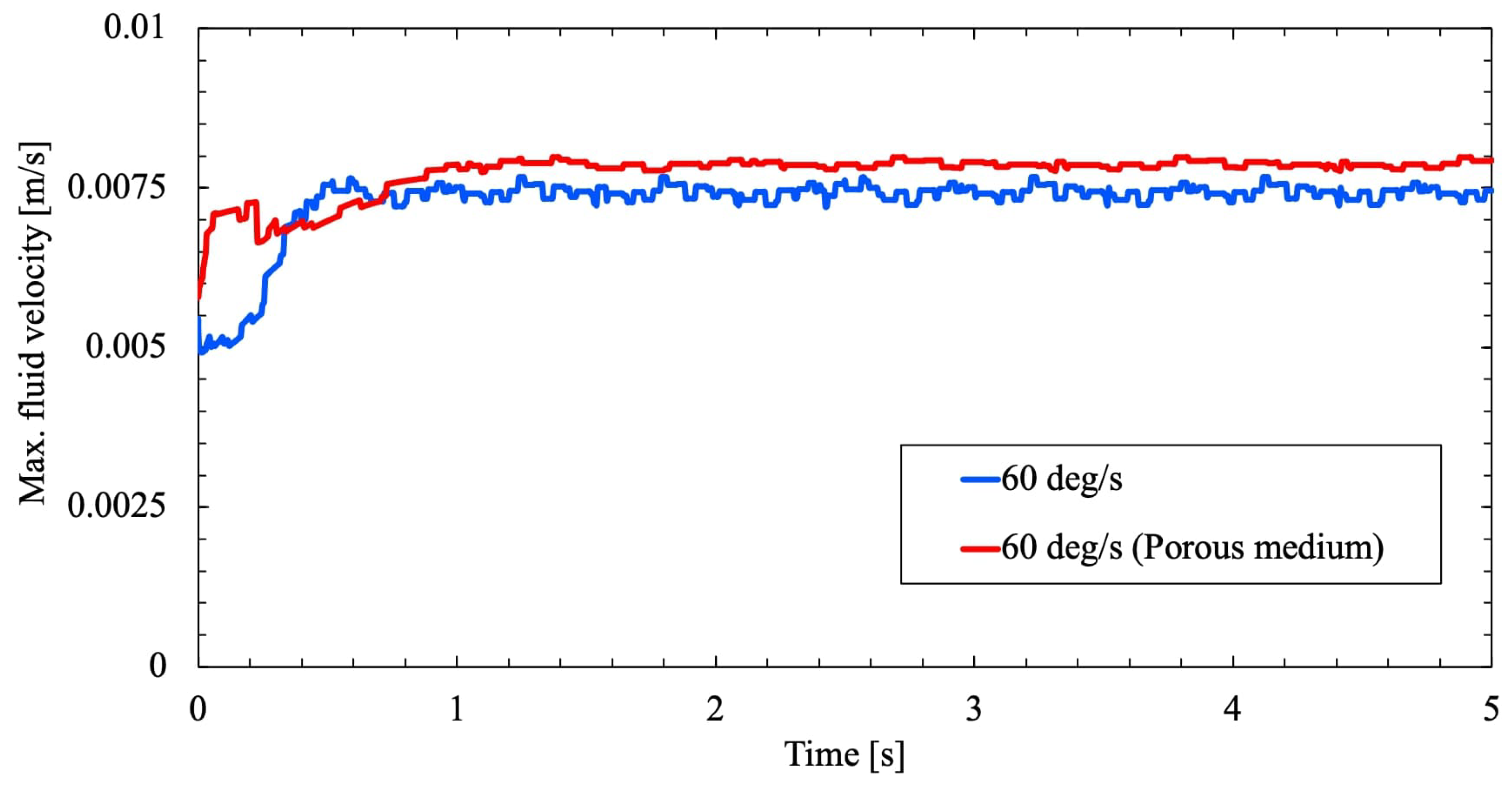
Figure 7 but not significantly. The presence of foreign medium assists in flow acceleration within the cylindrical flask and stirs momentum transfer in the fluid. Again, as discussed above the velocity field never reached a steady state. As the fluid circulation is opposed further due to rotation and the presence of the porous medium will eventually agitate further inversion of the fluid. A conceivable observation of the same is presented in
Figure 12, wherein velocity field of both the study agrees well and stays closer but flow acceleration is maximum near the flask wall.
3.4. Wall shear stress
Linear increase in flask rotational speed
and
invariably enhances the shear stresses along the flask wall as seen in
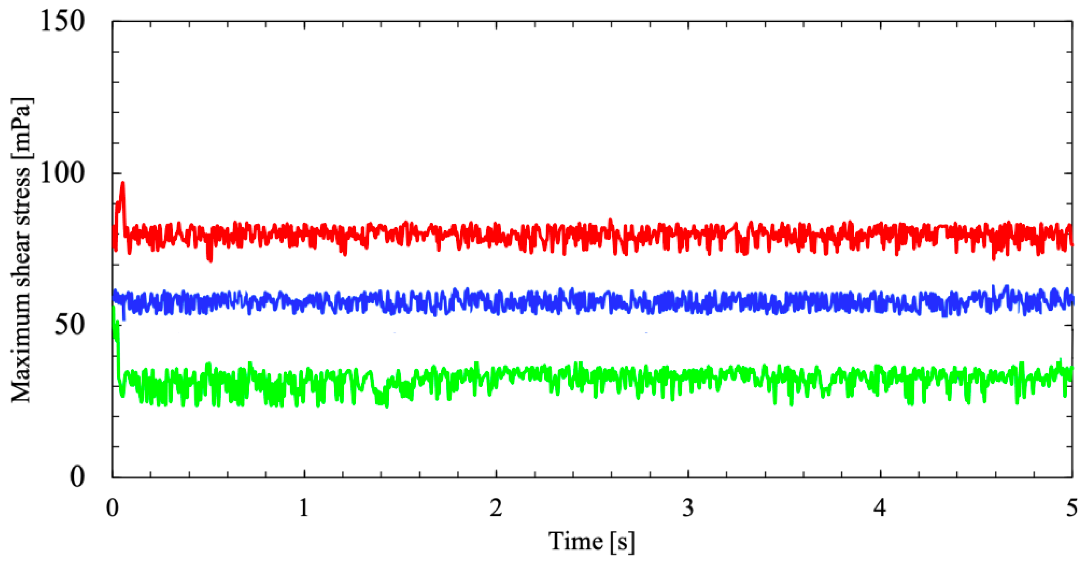
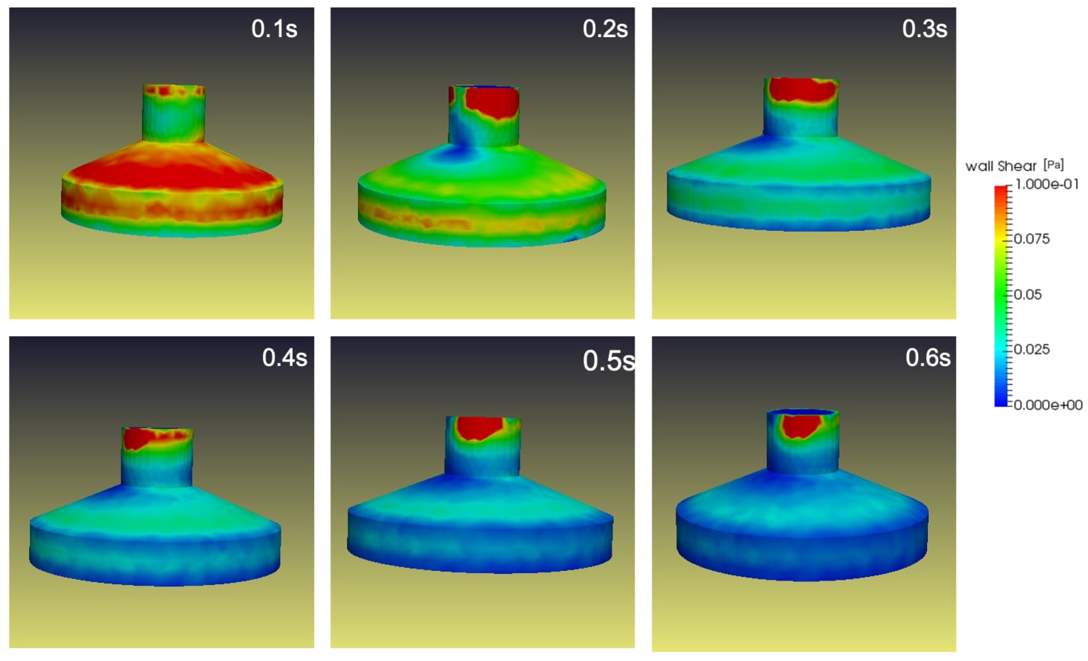
Figure 13. As the flask rotates in both frames of reference on the RPM with constant velocity, a cyclic transposition of fluid motion within the flask begins in a momentum transfer. Predominantly, this momentum transfer occurs in the boundary layer of the cylinder wall, as seen in
Figure 14. The rotating cylindrical flask will transport its momentum to the inverting fluid and will influence a high-wall shear.
As reviewed in
Section 3.2 the presence of a foreign medium will improve the flow acceleration within the flask which will directly improve the momentum transfer in the boundary layer region of the cylindrical flask wall.
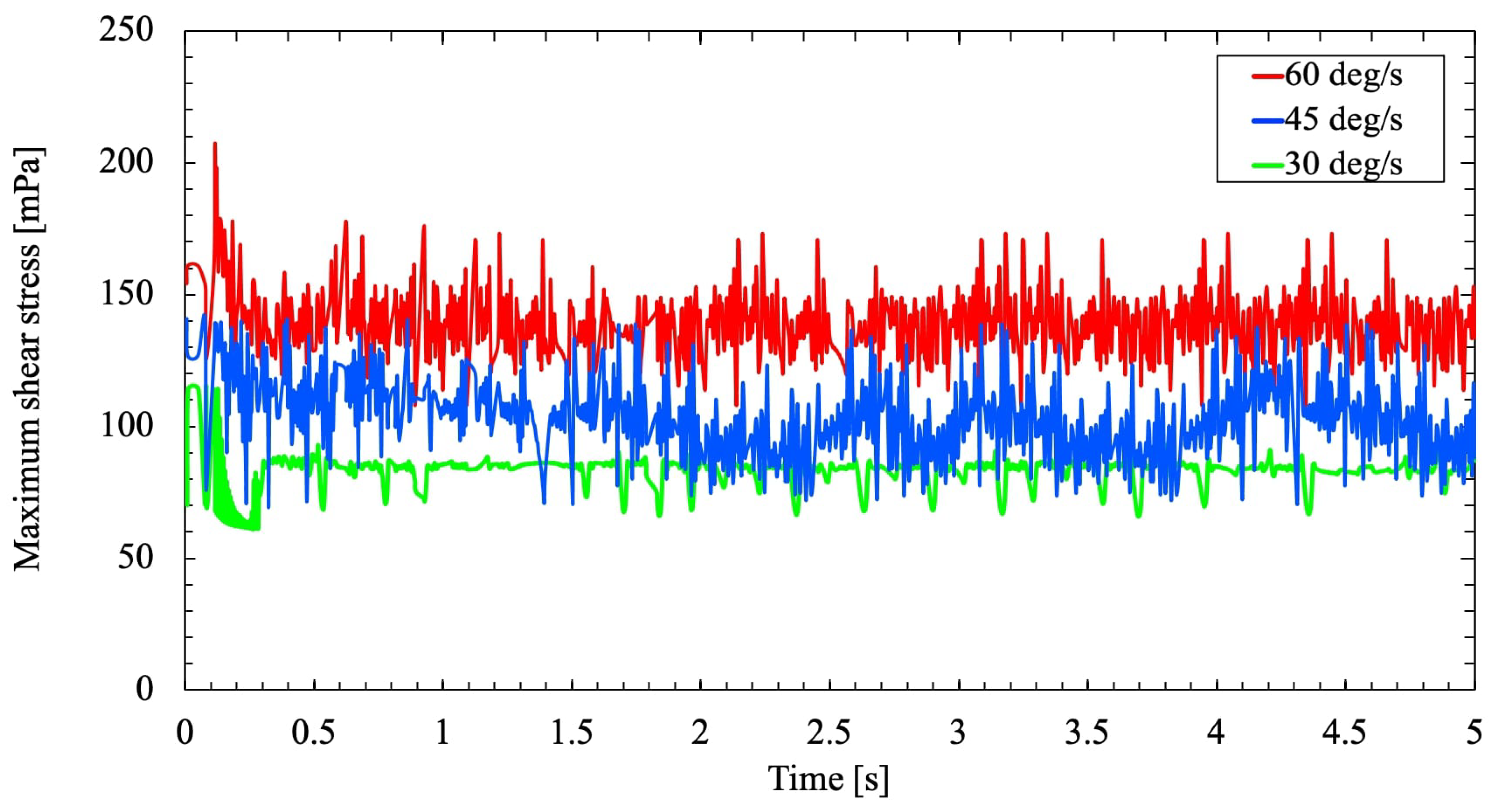
Figure 15 shows the variation in wall shear stress for the three different rotational velocities
and
. The highest shear stress is predicted as the rotational velocity increases gradually. Also,
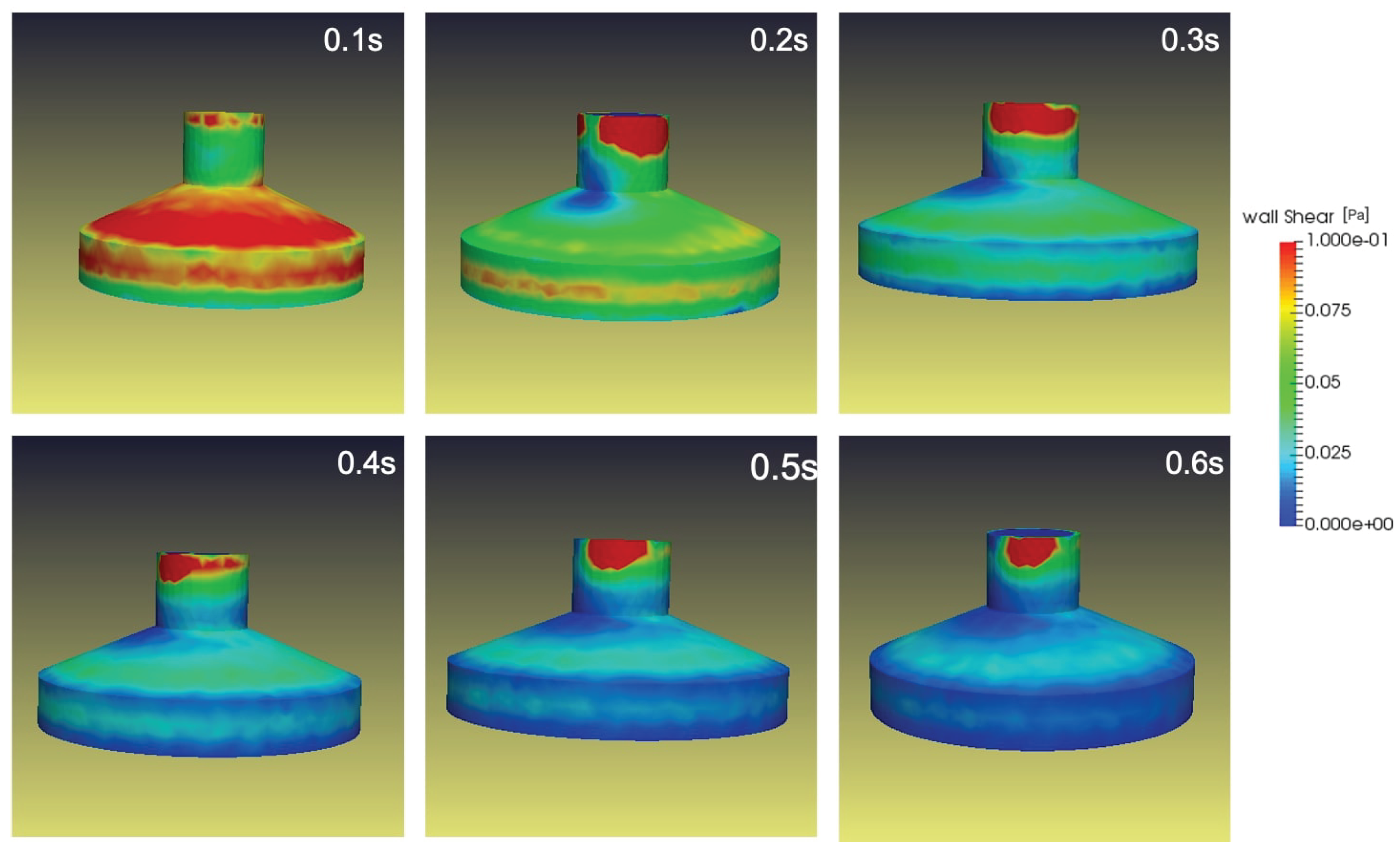
Figure 16 depicts the wall shear stress experienced by the flask at
when compared to
Figure 14, an increase in wall shear stress is experienced in
Figure 16 due to the presence of a porous medium. The study reveals that the increase in wall shear is along the flask’s top and on the side walls. Hence will have a minimal impact on the cells in the flask center, until or unless the cell temporarily exposes to the wall. At the max the cell will be exposed to a shear force of 0.025pa. While the cell plates were positioned at the RPM’s center of rotation to preserve
g, the impact of wall shear will have a minimal effect of the cell plates. Therefore, the cells will be purely exposed to
g but not impacted by the fluid shear.
4. Conclusion
The rotation of the RPM distributes local force to the fluid in addition to the earth’s gravity field over time. Henceforth, the need for a computational study arises for every biological study. The study depicts the complex convection and the addition of local forces adding up the shear force with in the system and more inclined towards the wall, henceforth will not affect the cells in the center. Thus the result indicate that the addition of porous medium in cultured flask will may impact the micro-gravity field with in the flask and not due to the varying fluid shear stress. Fewer cells from the computational grid exposes to higher shear stresses values, which are adding up to the maximum shear value and respond differently from the bulk population. The simulation results demonstrates the possible effects and the nature of the fluid motion in the flask and a notion of shear stresses and convection during such analysis.
Author Contributions
Praveen Laws: Conceptualization, Software, Methodology, Formal analysis, Writing original draft.
Funding
No funding for this project.
Institutional Review Board Statement
Not applicable.
Informed Consent Statement
Not applicable.
Data Availability Statement
The data in this article can be obtained by contacting the corresponding author.
Acknowledgments
The author wish to thank the Laboratory for Immuno Bioengineering Research and Applications (LIBRA), NewYork University, Abu Dhabi, for the support, interesting discussions and close collaboration.
Conflicts of Interest
The authors declare that they have no competing financial interest.
References
- Kiss, J.Z.; Wolverton, C.; Wyatt, S.E.; Hasenstein, K.H.; van Loon, J.J. Comparison of microgravity analogs to spaceflight in studies of plant growth and development. Frontiers in plant science 2019, 10, 1577. [Google Scholar] [CrossRef] [PubMed]
- Vogel, V. Mechanotransduction involving multimodular proteins: converting force into biochemical signals. Annu. Rev. Biophys. Biomol. Struct. 2006, 35, 459–488. [Google Scholar] [CrossRef] [PubMed]
- Mullender, M.; El Haj, A.; Yang, Y.; Van Duin, M.; Burger, E.; Klein-Nulend, J. Mechanotransduction of bone cells in vitro: mechanobiology of bone tissue. Medical and Biological Engineering and Computing 2004, 42, 14–21. [Google Scholar] [CrossRef] [PubMed]
- Wang, J.H.C.; Thampatty, B.P. An introductory review of cell mechanobiology. Biomechanics and modeling in mechanobiology 2006, 5, 1–16. [Google Scholar] [CrossRef] [PubMed]
- Gillespie, P.G.; Walker, R.G. Molecular basis of mechanosensory transduction. Nature 2001, 413, 194–202. [Google Scholar] [CrossRef] [PubMed]
- Hamill, O.P.; Martinac, B. Molecular basis of mechanotransduction in living cells. Physiological reviews 2001, 81, 685–740. [Google Scholar] [CrossRef] [PubMed]
- Buckey, J.C. Space physiology; Oxford University Press, USA, 2006.
- Williams, D.; Kuipers, A.; Mukai, C.; Thirsk, R. Acclimation during space flight: effects on human physiology. Cmaj 2009, 180, 1317–1323. [Google Scholar] [CrossRef] [PubMed]
- Fitts, R.H.; Riley, D.R.; Widrick, J.J. Invited review: Physiology of a microgravity environment: microgravity and skeletal muscle. J Appl Physiol 2000, 89, 823–839. [Google Scholar] [CrossRef] [PubMed]
- Fitts, R.H.; Riley, D.R.; Widrick, J.J. Functional and structural adaptations of skeletal muscle to microgravity. Journal of Experimental Biology 2001, 204, 3201–3208. [Google Scholar] [CrossRef] [PubMed]
- Kraft, T.F.; van Loon, J.J.; Kiss, J.Z. Plastid position in Arabidopsis columella cells is similar in microgravity and on a random-positioning machine. Planta 2000, 211, 415–422. [Google Scholar] [CrossRef] [PubMed]
- Borst, A.; Van Loon, J.J. Technology and developments for the random positioning machine, RPM. Microgravity science and technology 2009, 21, 287–292. [Google Scholar] [CrossRef]
- Wuest, S.L.; Richard, S.; Kopp, S.; Grimm, D.; Egli, M. Simulated microgravity: critical review on the use of random positioning machines for mammalian cell culture. BioMed research international 2015, 2015. [Google Scholar] [CrossRef] [PubMed]
- Meslnad, D. Novel ground-based facilities for research in the effects of weight. Microgravity News from ESA 1996, 9, 5–10. [Google Scholar]
- Van Loon, J.J. Some history and use of the random positioning machine, RPM, in gravity related research. Advances in Space research 2007, 39, 1161–1165. [Google Scholar] [CrossRef]
- Jasak, H. Error analysis and estimation for the finite volume method with applications to fluid flows. 1996.
- Hafsteinsson, H.E. Porous media in OpenFOAM. Chalmers University of Technology, Gothenburg 2009.
- Menter, F.R. Two-equation eddy-viscosity turbulence models for engineering applications. AIAA journal 1994, 32, 1598–1605. [Google Scholar] [CrossRef]
- Wilcox, D.C.; others. Turbulence modeling for CFD; Vol. 2, DCW industries La Canada, CA, 1998.
- Wuest, S.L.; Richard, S.; Walther, I.; Furrer, R.; Anderegg, R.; Sekler, J.; Egli, M. A novel microgravity simulator applicable for three-dimensional cell culturing. Microgravity science and technology 2014, 26, 77–88. [Google Scholar] [CrossRef]
- ElGindi, M.; Sapudom, J.; Laws, P.; Garcia-Sabate, A.; Daqaq, M.F.; Teo, J. 3D microenvironment attenuates simulated microgravity-mediated changes in T cell transcriptome. Cellular and Molecular Life Sciences 2022, 79, 508. [Google Scholar] [CrossRef] [PubMed]
- Liu, F. A thorough description of how wall functions are implemented in OpenFOAM. Proceedings of CFD with OpenSource Software 2016, pp. 1–33.
- Gschaider, B. OpenFOAM guide/The PIMPLE algorithm in OpenFOAM, 21.08.2017.
- van Loon, J.J.; Folgering, E.H.; Bouten, C.V.; Veldhuijzen, J.P.; Smit, T.H. Inertial shear forces and the use of centrifuges in gravity research. What is the proper control? Journal of biomechanical engineering 2003, 125, 342–346. [Google Scholar] [CrossRef] [PubMed]
- Wuest, S.L.; Stern, P.; Casartelli, E.; Egli, M. Fluid dynamics appearing during simulated microgravity using random positioning machines. PloS one 2017, 12, e0170826. [Google Scholar] [CrossRef]
|
Disclaimer/Publisher’s Note: The statements, opinions and data contained in all publications are solely those of the individual author(s) and contributor(s) and not of MDPI and/or the editor(s). MDPI and/or the editor(s) disclaim responsibility for any injury to people or property resulting from any ideas, methods, instructions or products referred to in the content. |
© 2024 by the authors. Licensee MDPI, Basel, Switzerland. This article is an open access article distributed under the terms and conditions of the Creative Commons Attribution (CC BY) license (http://creativecommons.org/licenses/by/4.0/).
