Preprint
Article

Enhancing Thermal Conductivity of CNT/AlN/Silicone Rubber Composites through Directly Grown CNTs on AlN for Reduced Filler Filling Ratio

Altmetrics

Downloads

92

Views

42

Comments

0

A peer-reviewed article of this preprint also exists.

Submitted:

27 February 2024

Posted:

27 February 2024

You are already at the latest version

Alerts
Abstract
Achieving the thermal conductivity required for efficient heat management in semiconductors and other devices requires the integration of thermally conductive ceramic fillers at concentrations of 60 vol% or higher. However, the increased filler content often negatively affects the mechanical properties of the composite matrix, limiting its practical applicability. To address this issue, in this paper, we present a new strategy to reduce the required ceramic filler content: the use of a thermally conductive ceramic composite filler with carbon nanotubes (CNT) grown on aluminum nitride (AlN). We have combined catalyst coating technology with vacuum filtration to ensure that the catalyst is uniformly applied to micrometer-sized AlN particles, followed by efficient and uniform synthesis of CNTs using a water-assisted process in a vertical furnace. By carefully controlling the number of vacuum filtration cycles and the growth time of the CNTs, we demonstrate precise control over the number and length of the CNT layers, thereby adjusting the properties of the composite to the intended specifications. When AlN/CNT hybrid fillers are incorporated into silicone rubber, while maintaining the mechanical properties of rubber, the thermal diffusivity achieved at reduced filler levels exceeds that of composites using AlN-only or simultaneous AlN and CNTs formulations. This demonstrates the critical role of CNTs on AlN surfaces. Our study represents a significant advancement in the design of thermally conductive materials with potential implications for a wide range of applications.
Keywords: 
Subject: Chemistry and Materials Science  -   Nanotechnology

1. Introduction

The rise in demand for compact electronic devices and high-power LED lighting systems has underscored the critical importance of efficient thermal management alongside advances in battery and device technology [1,2,3,4]. As a critical aspect of thermal management, the effective dissipation of heat generated by the devices to the surrounding environment has received considerable attention. These include the use of various techniques, methods, and materials aimed at minimizing thermal resistance and utilizing materials with high thermal conductivity [4,5,6,7]. Among these, thermal interface materials (TIMs) are increasingly emerging as critical components that bridge the gap between heat sources (e.g., devices) and heat sinks (typically metal surfaces) [3,4,8]. Previous research has explored various avenues, including the integration of high thermal conductivity metals and alloys [5,9], carbon-based materials such as graphene, graphene oxide (GO), and carbon nanotubes (CNTs) [10,11,12,13], and ceramic fillers such as aluminum nitride (AlN), boron nitride (BN), silicon carbide (SiC), aluminum oxide (Al2O3), and zinc oxide (ZnO) [14,15,16,17,18,19,20,21] into silicone rubber or epoxy resin matrices. In addition, efforts have extended to the development of composite materials with malleable thermally conductive fillers capable of conforming to intricate device and heat sink geometries, thereby improving processability and heat dissipation efficiency [22,23].
AlN exhibits remarkable properties including corrosion resistance, wear resistance, and exceptional thermal stability. Compared to materials such as Al2O3 (25–40 W/(m K)) [24] and silicon nitride (Si3N4, 180 W/(m K)) [25], AlN has a significantly higher isotropic thermal conductivity range (170-230 W/(m K), with a theoretical upper limit of 320 W/(m K)) [26]. This level is comparable with the isotopically high thermal conductivity of h-BN (in-plane: 200–280 W/(m K)) [27], a material characterized by its anisotropic thermal behavior. In addition, AlN has a remarkable electrical resistivity (> 1014 Ω cm), a coefficient of thermal expansion similar to that of silicon semiconductors (4.3 × 10⁻⁶ K-1 at room temperature) and is resistant to the halogen gas plasma often used in semiconductor manufacturing processes [28]. These properties make AlN a promising ceramic filler candidate for improving the thermal conductivity of resins and rubbers [14,29,30].
Despite the remarkable properties of AlN, its susceptibility to water-induced instability is a serious problem. When exposed to moisture, AlN oxidizes, denitrates, and hydrolyzes to form aluminum hydroxide and corrosive ammonia. The result is a decrease in thermal conductivity as the formation of non-thermal species takes precedence. Improving water resistance becomes an indispensable pursuit as we move toward the practical use of high thermal conductivity ceramic fillers such as AlN [31,32,33,34,35,36]. Generally, in order to effectively manage heat in semiconductors and similar devices, it is imperative to incorporate thermally conductive ceramic fillers at concentrations exceeding 60 % by volume, thereby attaining the necessary thermal conductivity (Figure 1a). While increasing filler content increases thermal conductivity, it also affects the mechanical properties of TIM composites. Critical properties, such as tensile strength and elongation, are susceptible to decrease [37,38]. In addition, increasing filler content affects the inherent flexibility of matrix resins or rubbers and subsequently compromises thermal dissipation efficiency by degrading adhesion to the contact surfaces of devices and heat sinks. Therefore, a critical challenge in the quest for superior thermal transfer properties remains - strengthening the stability of AlN coupled with strategies to reduce the filler content in the rubber or resin matrix while maintaining high thermal conductivity.
Numerous efforts have focused on reducing the need for high AlN filler concentrations, including strategies such as particle coarsening and amalgamation with other fillers. On the other hands, the methods often result in the field of improving AlN stability, particularly in terms of thwarting hydrolysis, has spawned diverse approaches. These include chemical treatments, such as surface conditioning and surfactants, that modify the surface chemistry [33]. In addition, shielding layers of materials such as GO, yttrium oxide (Y2O3), and silicon oxycarbonitride ceramics have been used to encapsulate AlN surfaces and insulate them from hydrolysis [34,35,36]. However, there is a potential problem: the inadvertent deposition of materials with inferior thermal conductivity compared to AlN could obstruct thermal conduction pathways, resulting in a decrease in overall thermal conductivity. In addition, the presence of organic substances, including surfactants, can induce coalescence in processes such as AlN powder molding and sintering [32]. It may also affect stability and mechanical properties of rubber or resin compounds that interact with matrix components. Furthermore, coatings containing conductive substances, such as GO, could potentially affect the insulating properties of AlN [32]. While reports utilizing these strategies increase water resistance, they do not report on the critical issue of reducing the filler content within the composite matrix.
CNTs, analogous to GO in their function of enhancing AlN stability (water resistance), have recently received considerable attention as potential fillers for high thermal conductivity composites, particularly TIMs. CNTs have a one-dimensional (1D) configuration, high aspect ratio, and remarkable thermal conductivity (3000 W/(m K) for individual multiwall carbon nanotubes (MWCNTs) and 200 W/(m K) for bulk multi-walled CNTs at room temperature). Possessing these properties, MWCNTs represent a promising high thermal conductivity filler, similar to AlN [41,42,43,44]. While pure silicone rubber typically possesses a low thermal conductivity (0.1–0.3 W/(m K)), both corrosion resistance and thermal conductivity significantly improve when filled with high thermal conductivity ceramic powders [24]. This improvement in properties expands its range of applications. The blending with CNTs has demonstrated increased thermal conductivity and reduced the required filler content in a composite, including those with ceramic fillers such as AlN and CNTs [20,41]. However, the simultaneous integration of ceramics, such as AlN and CNTs can be complicated. In addition, the difficulty of AlN stabilization (water resistance) persists, and the presence of non-contributing CNTs within thermal pathways can potentially trigger a decline in mechanical properties due to the need for increased filler content (Figure 1c).
We have previously reported the success synthesis of vertically aligned CNTs on AlN flat substrates using water-assisted chemical vapor deposition (CVD), “super-growth method” [45]. The commonly used vapor phase deposition of Fe catalyst is not suitable for the deposition of spherical particles as shown in Figure 1. In this paper, we present a new strategy to reduce the filler content of AlN and improve the water resistance of AlN: CNT/AlN filler, in which CNTs are grown on AlN particles used as a thermal conductive filler, as shown in Figure 1d. Specifically, we have focused on the application of Fe catalyst coating methods to both AlN filler particles and CNT synthesis processes. In this pursuit, we have used wet-based catalyst coating techniques, in particular dip coating and vacuum filtration coating, to coat AlN particles with the Fe catalyst. We then proceeded to vertically grow CNTs directly on the AlN particles, a step aimed at improving the water resistance of AlN. In addition, we demonstrate the exceptional properties of this CNT/AlN composite as a thermally conductive filler in silicone rubber matrices. By creating efficient thermal conduction pathways within the matrix, as shown in Figure 1d, we increased thermal conductivity at reduced filler content. For this purpose, we directly mixed CNT/AlN particles with the silicone rubber. In the process of this study, we have successfully exercised precise control over the structural properties (length and number of layers) of the synthesized CNTs. This was made possible by meticulously adjusting the catalyst coating conditions applied to AlN particles and regulating the CNT synthesis duration through a straightforward methodology. Moreover, by integrating the synthesized CNT/AlN filler with silicone rubber, we have achieved about twice the thermal conductivity of AlN alone at about half the filler addition rate, while maintaining the mechanical properties of rubber. This was evident when compared with previous reports involving other strategies of AlN-based composites either in isolation or in conjunction with CNTs.

2. Materials and Methods

2.1. Coating of Fe catalyst onto AlN particles

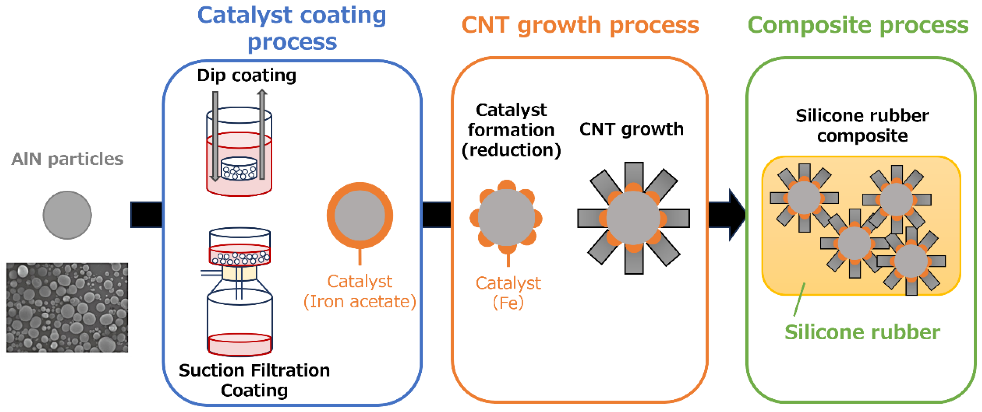
AlN particles selected for this study had a particle size distribution characterized by D50 = 80 µm and D90 = 122 µm (HFS-80, Tokuyama Corporation). Prior to use, these AlN particles were ultrasonically cleaned using acetone and ethanol for 5 minutes, followed by vacuum drying at 100 °C. The dried AlN particles were then immersed in a 30 mM (CH3COO)2Fe / ethanol solution. A vacuum pump and filter were used for the vacuum filtration coating procedure. This setup facilitated the controlled filtration of the iron acetate solution onto the surfaces of the AlN particles, resulting in the deposition of iron acetate (Fe catalyst) onto the AlN substrates. To achieve the desired amount of iron acetate deposition, both the deposition and vacuum filtration steps were repeated iteratively, ranging from 1 to 5 cycles. In the dip coating process, the prepared dried AlN particles were enclosed in a stainless steel mesh container. This container had an aperture size of 0.20 mm, a wire diameter of 0.53 mm, and an open porosity of 62.6 %. The AlN loaded container was then immersed in a 30 mM (CH3COO)2Fe / ethanol solution. The container was pulled out of the solution at a controlled rate of 0.5 mm/sec, and this immersion/pulling sequence was repeated three times as shown in the catalyst coating process in Figure 2.

2.2. Synthesis of vertically aligned CNTs on Fe/AlN particles

AlN particles coated with iron acetate (Fe catalyst) by both vacuum filtration and dip coating methods were introduced into a mesh dish with an aperture size of 0.35 mm, a wire diameter of 0.21 mm, and an open porosity of 29.9 %. This mesh dish was then placed in a horizontal 1-inch quartz tube furnace. The temperature of the furnace was ramped up to 750 °C at a controlled rate of 50 °C/min. The furnace was then held at this temperature for an additional 10 minutes while maintaining an atmosphere of H2:N2 at a ratio of 9:1. This particular environment was designed to facilitate the formation of Fe catalyst nanoparticles. Next, the synthesis of CNTs was performed using water-assisted chemical vapor deposition (CVD). A mixture consisting of a carbon feedstock of C2H2 (0.5 %), a growth enhancer of H2O at a concentration of about 250 ppm, and an N2 carrier gas was introduced into the furnace. This introduction was carried out over a period of 0–20 min while maintaining the temperature at 750°C. This process, shown in Figure 2 as the CNT growth process, allowed the growth of vertically aligned CNTs [46].

2.3. Preparation of CNT/AlN/silicone rubber nanocomposites

The preparation of CNT/AlN/silicone rubber nanocomposites followed a standardized protocol [47]. First, CNT/AlN particles were dispersed directly into a silicone precursor (KE-106 silicone rubber base compound, Shin-Etsu Chemical Co., Ltd.) by overnight stirring at 50 rpm. A curing agent (CAT-RG, Shin-Etsu Chemical Co., Ltd.) was then added to the CNT/silicone precursor mixture at a weight ratio of 10% with respect to the silicone precursor. The resulting mixture was homogenized and degassed using a planetary centrifugal vacuum mixer (ARV-310, THINKY Co., Ltd.). To fabricate the CNT/AlN/silicone rubber nanocomposites, the mixture was hardened in a heated mold under a pressure of approximately 10 MPa at 150 °C for 30 min (Figure 2, Composite Process). This process resulted in the formation of the CNT/AlN/silicone rubber nanocomposites.

2.4. Characterizations

The color difference between Fe/AlN particles subjected to suction filtration and dip coating was evaluated using a colorimeter/whiteness meter (NW-12, Nippon Denshoku Industries CO., LTD.) with a sample size (n) of 10. The Fe and Al contents were quantified using a fluorescence X-ray instrument (EDXL 300, Rigaku Corporation with n = 5. Both digital microscopy (VHX-5000, Keyence) and scanning electron microscopy (SEM; VE-9800, Keyence) were used to investigate the general morphology of CNTs on AlN particles. The determination of the CNT length from the AlN surface to the CNT tip with the SEM images was performed using the SEM software. A minimum of 20 samples were taken for each sample. Quantification of the CNT layers was performed by transmission electron microscopy (TEM; EM-002B, TOPCON). For TEM observations, CNT-ethanol dispersions were deposited on Cu TEM grids, and the number of layers was measured over more than 50 CNTs. The thermal diffusivity (through plane) of the CNT/AlN/rubber composite was evaluated at room temperature under ambient conditions using a flash analyzer (LFA-464, NETZSCH) equipped with a Xenon lamp. To visualize the thermal conduction pathways (CNT/AlN) within the silicone rubber, the rubber was immersed in chloroform. Dissolution of the silicone rubber was carried out by stirring at high speed (500 rpm) overnight using a high-speed shaker (ASCM-1, High-Speed Shaker, AS ONE Corporation). After dissolution, the resulting sample (CNT/AlN) was observed by SEM.

3. Results and discussion

3.1. Coating of Fe catalyst on AlN particles

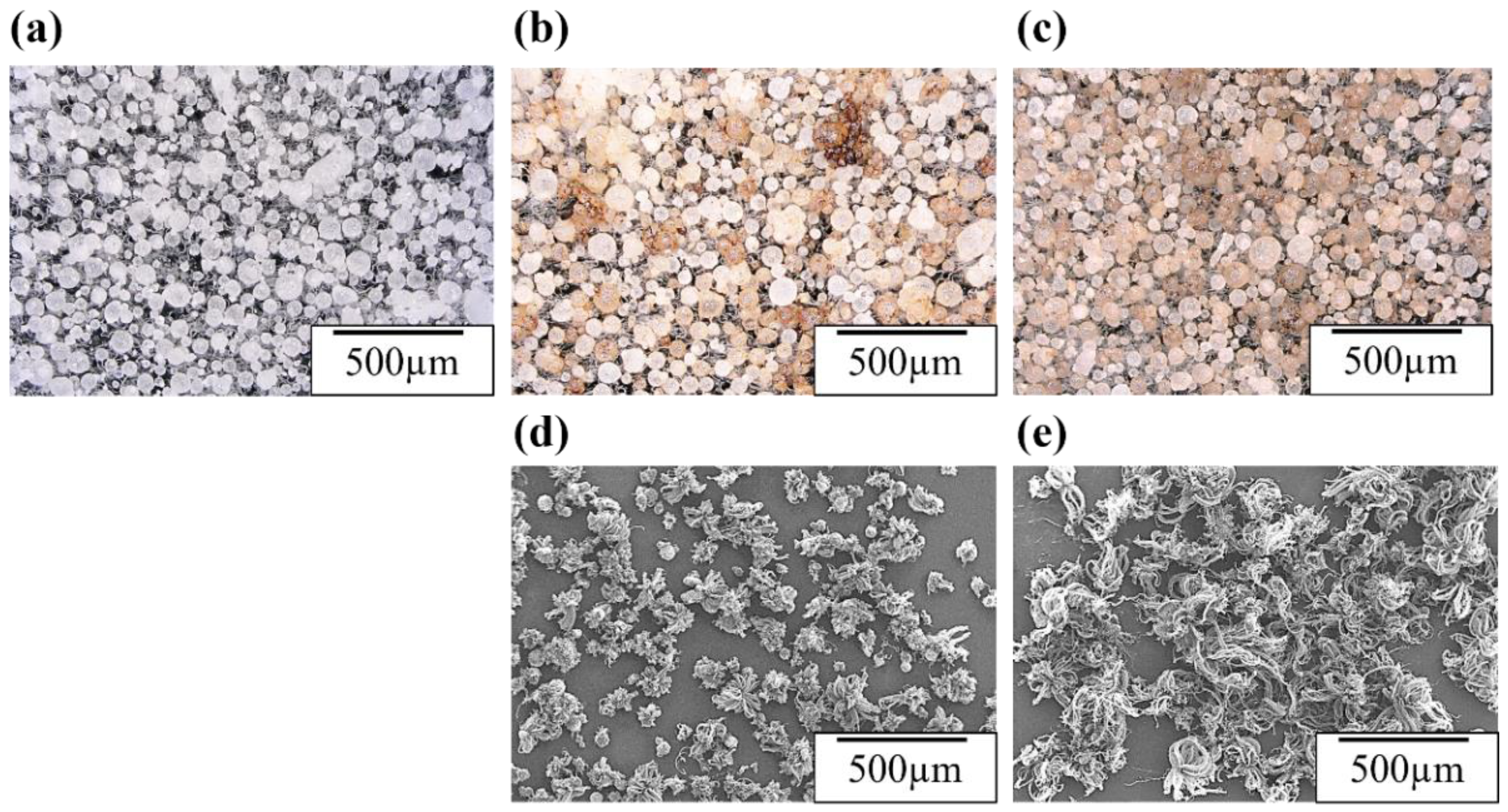
First, we investigated how the uniformity of Fe catalyst on AlN particles changes with different catalyst coating methods. In particular, we found that Fe acetate as a catalyst source could be more uniformly distributed on the AlN particle surface by suction filtration compared to dip coating. The uniform distribution of Fe acetate was confirmed by color difference measurements. When Fe (II) acetate was applied to AlN, the sample surface changed to a reddish-brown color. This color change was quantified in the L*a*b* color space, a color model commonly used to represent object colors. In the Lab color space, both a* and b* values become positive: L* represents lightness, a* represents the green-to-red direction, and b* represents the blue-to-yellow direction [48]. As the values increase, the color becomes more vivid, while values near the center (where a* and b* are both zero) indicate more muted colors. In essence, a thicker (higher amount of) Fe acetate (Fe catalyst) coating on AlN results in increased a* and b* values, resulting in decreased brightness (L*). Digital microscope images of AlN particles before Fe catalyst coating, AlN particles with Fe acetate (Fe catalyst) coating via suction filtration or dip coating (100 °C, 1 hour, vacuum dried) are shown in Figure 3a–c. In addition, Table 1 shows the mean and standard deviation of color differences for AlN particles and Fe/AlN particles measured at 10 points for each condition. From the visual inspection in Figure 3 and the comparison of color differences in Table 1, it is evident that the use of suction filtration to apply a 30 mM Fe acetate solution resulted in a more uniform distribution of Fe acetate compared to dip coating. When comparing the color differences, the dip coating (a* = 3.5±1.9, b* = 18.9 ± 3.4, L* = 82.8 ± 4.2) showed color differences similar to the suction filtration coating (applied 5 times) (a* = 3.9 ± 1.1, b* = 15.6 ± 1.9, L* = 77.4 ± 2.8), but with approximately half the standard deviation. This quantitative assessment by color difference confirms the uniform distribution of Fe acetate (Fe catalyst) not only visually but also quantitatively. Similar results are obtained from the semi-quantitative values of Al and Fe, as well as the standard deviation of the Al/Fe ratio obtained from X-ray fluorescence (XRF) measurements as shown in Table S1. In addition, a comparison of coating repetition (3 vs. 5 times) in Table 1 shows that repeated application of the same 30 mM solution by suction filtration led to an increase in color differences, with a*: 1.6 to 3.9, b*: 10.3 to 15.6, and L*: 79.3 to 77.4. This shift indicates a darker red-brown color attributed to Fe acetate (Fe catalyst). This result illustrates how the amount of Fe acetate on AlN particles (Fe catalyst film thickness) can be controlled by adjusting the number of suction filtration rounds, demonstrating the potential of this simple technique for controlling the amount of Fe acetate through filtration repetitions.
Next, we demonstrate the controlled and uniform synthesis of CNTs on AlN particles coated with Fe catalyst using either suction filtration or dip coating methods. Figure 3d-e show SEM images of CNTs synthesized by the CVD method on Fe acetate/AlN substrates prepared by suction filtration or dip coating, respectively. When the Fe catalyst was applied by suction filtration, the CNTs grew uniformly, while dip coating resulted in non-uniform CNT growth, with some particles showing no CNT growth at all. In fact, CNT length measurements from SEM images in Figure 3d-e confirmed CNT lengths of 350±52 µm and 368±97 µm for suction filtration and dip coating, respectively. The smaller error in CNT length for suction filtration further supports the uniform growth of CNTs. Although the resultant CNT growth is highly dependent on the synthesis conditions, they are also strongly dependent on the thickness and uniformity of the Fe catalyst coating as well as the support layer (such as Al2O3) [49]. Essentially, under synthesis conditions where the carbon source gas (such as ethylene) is uniformly fed to the Fe catalyst on AlN particles, optimal CNT growth conditions vary with Fe catalyst thickness. Consequently, the non-uniform CNT growth observed in the dip coating (as shown in Figure 2a) suggests that the non-uniform thickness of the Fe acetate catalyst layer is a contributing factor. This notion is consistent with the results of the uniformity of the Fe catalyst coating as indicated by the color difference data shown in Figure 3d-e and Table 1.

3.2. Control of CNT growth on AlN particles

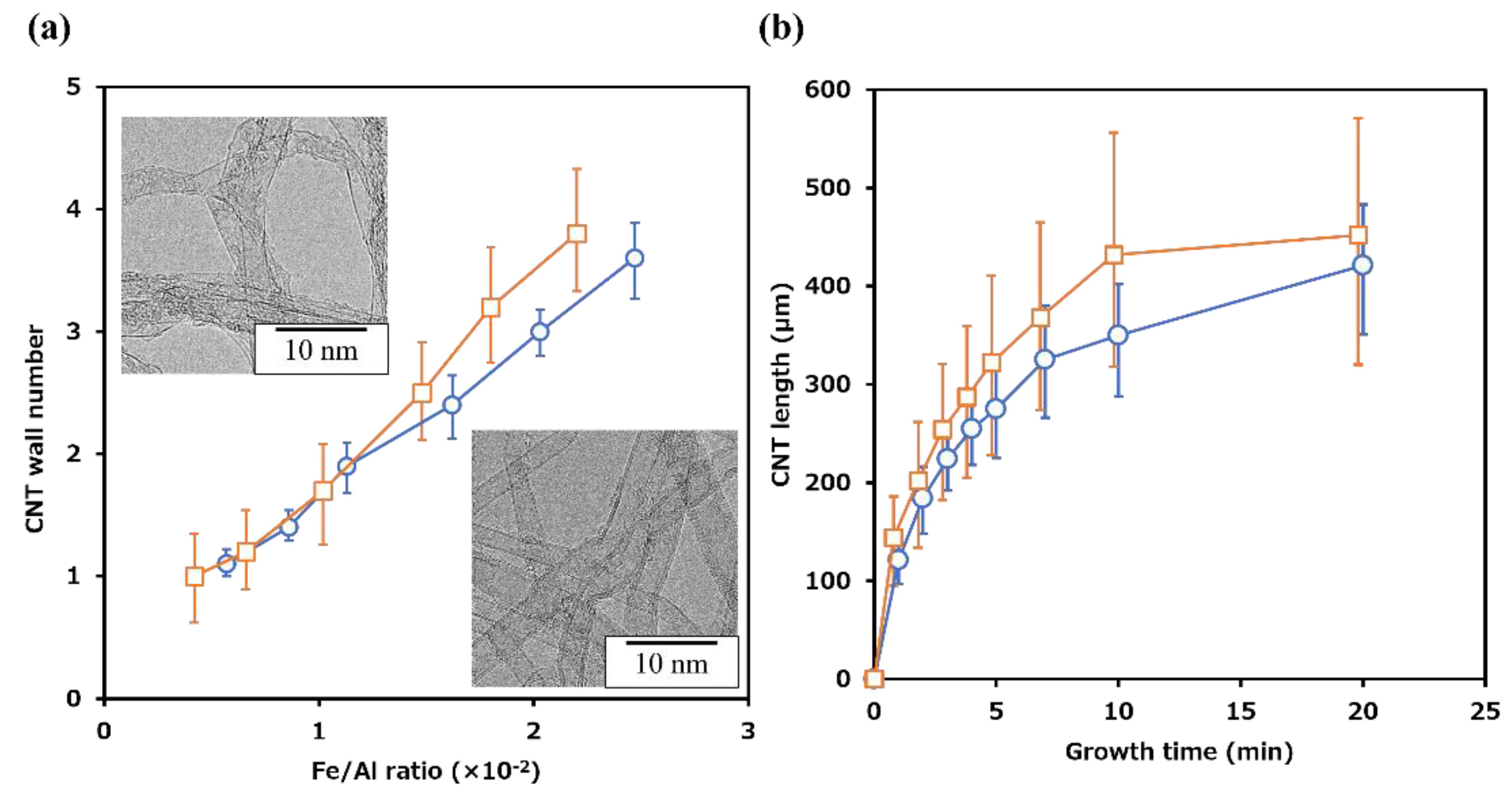
We further investigated the influence of the catalyst coating methods, namely suction filtration and dip coating, on the growth of CNTs on Fe/AlN particles. The number of CNT layers was determined from TEM images (n = 50, as shown in the inset of Figure 4a) of CNTs synthesized on Fe/AlN particles coated by both methods. The relationship between the Fe-to-Al ratio on AlN and the number of CNT layers was established and shown in
Figure 4a. The Fe-to-Al ratio was calculated from the Fe and Al content (%) obtained by X-ray fluorescence analysis of Fe/AlN particles, and the average value of ten measurements was considered as the Fe/Al ratio. In addition, the adjustment of the Fe acetate (Fe catalyst) content in the dip coating was controlled by modifying the number of dip cycles, similar to the suction filtration: an increase in the number of dips resulted in a higher Fe acetate content. Regardless of the catalyst coating method, an increase in the Fe/Al ratio corresponded to an increase in the number of CNT layers synthesized. However, when comparing the error bars on each plot showing the layer number distribution, the layer number distribution was narrower for suction filtration synthesis compared to dip coating. We clarified the relationship between the thickness (deposition amount) of the Fe catalyst and the number of CNT layers. An increase in the thickness of the Fe catalyst resulted in an increase in the number of CNT layers (diameter). This trend is consistent with previous research indicating that the observed increase in number of layers of the CNTs with the increased Fe thickness likely results from the increase in the average catalyst nanoparticle size which has been reported previously [52].
Therefore, the wider distribution of layer counts observed in dip coating can be attributed to the lower uniformity of catalyst thickness, while suction filtration, which allows for uniform catalyst application, showed a narrower layer count distribution. Figure 4b illustrates the relationship between CNT length (from the AlN particle surface to the CNT tip) and synthesis time. The CNT length was measured from SEM images using the measurement software provided with SEM, and measurements were taken for 30 CNT/AlN particles to calculate the average length and deviation. Figure 4b shows that regardless of the coating method, the CNT length increased with longer synthesis times. These growth processes are consistent with previous findings and confirm the ability to control the CNT length on AlN particles by adjusting the synthesis time [50].
From these results, we demonstrated the feasibility of controlling the number of CNT layers (diameter) and length grown on AlN substrates using the simple adjustment methods of Fe catalyst coating, either by the number of dips in dip coating or the synthesis time. Furthermore, we found that the ability of suction filtration to uniformly coat the Fe catalyst leads to uniform CNT growth, which is different from dip coating. These results are important as the number of CNT layers are two factors which determine the electrical and thermal properties. We realize that a number of other factors such as straightness and absence of crystalline defects, within the scope of our synthetic control, we found that as the number of layers increase, the thermal conductivity of the CNTs improved. Further, we found that CNTs with 2–3 layers have the highest electrical conductivity [51,52]. On the other hand, CNT length affects not only electrical and thermal properties, but also mechanical properties. Longer CNTs lower the percolation threshold and improve electrical conductivity and tensile strength when used to fabricate CNT films [53,54]. The process presented in this paper, which facilitates the control of CNT structures (number of layers and length) in a straightforward manner, is well suited for synthesizing CNTs with tailored properties and creating composites with application-specific material properties.

3.3. Thermal properties of CNT/AlN/Slicon rubber composites

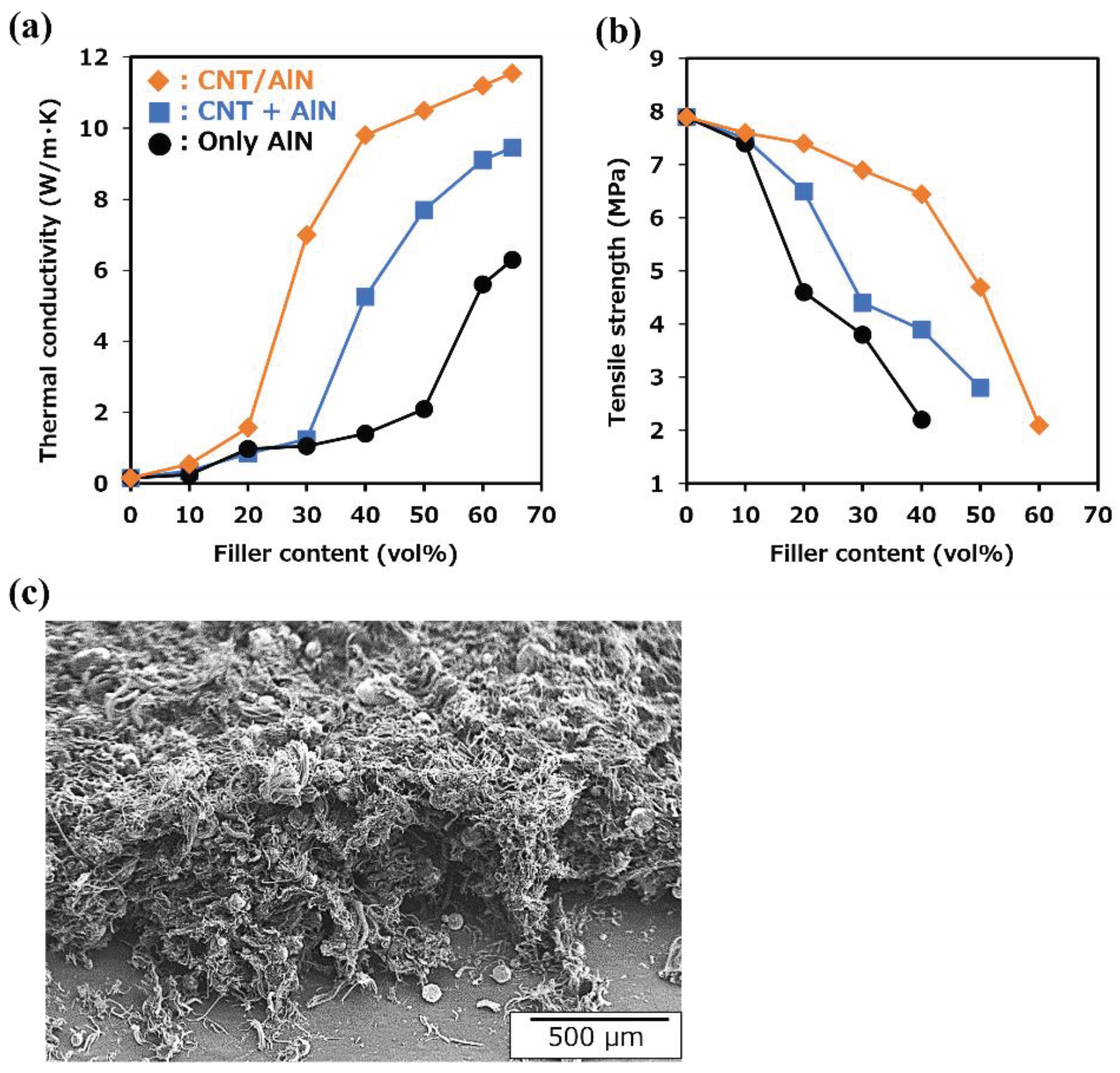
Using the suction filtration method to uniformly coat Fe catalyst and enable uniform growth of CNTs on AlN particles (CNT/AlN composite fillers), we fabricated composites by combining these fillers with silicone rubber (CNT/AlN/silicone rubber composites). We have demonstrated that these composites exhibit superior thermal properties at lower filler content than that of the AlN alone and AlN with CNTs (AlN + CNT). Specifically, we fabricated CNT/AlN composite fillers and silicon rubber composites and examined the relationship between thermal conductivity and filler content. Figure 5a shows the thermal conductivity of composites consisting of AlN only, simultaneous addition of AlN and CNTs, and CNT/AlN composite fillers synthesized by the suction filtration method for Fe catalyst deposition on AlN added to silicon rubber (CNT/AlN/silicon rubber composites). The preparation conditions of the CNT/AlN composite fillers used in Figure 5a were adjusted to be structurally similar to CNTs (ZEONANO® SG101) when added simultaneously with AlN [55]. The filtration cycle in suction filtration was set to three (Fe/Al ratio: 0.0066) using Fe/AlN particles with an average layer number of 1.2 and an average length of 350 µm (10 min synthesis time). With the incorporation of CNT/AlN composite fillers, the onset of the thermal conductivity increases for composites containing AlN only or both AlN and CNTs occurred at relatively high filler contents (50 vol% and 30 vol%, respectively). In contrast, for the CNT/AlN composite exhibited an exceptionally low onset filling level at ~20 vol%. In addition, the filler content required to achieve ~20 W/mK occurs at 30 vol%, ~45 vol%, and > 60 vol% for CNT/AlN, AlN + CNT, and AlN, respectively. Furthermore, the maximum observed thermal conductivity occurred for the CNT/AlN composite and at a relatively low filler content. This result demonstrates the importance of incorporating the CNT and AlN into the polymer matrix together rather than as separate components.
The use of CNT/AlN composite fillers facilitates the formation of thermal conduction paths by bonding CNTs to AlN particles, resulting in a lower minimum filler content (percolation threshold) required to exhibit thermal conductivity, as shown in the conceptual diagram in Figure 1. In addition, by using CNT/AlN composite fillers, the non-contributing CNTs and AlN in terms of thermal conductivity are minimized by the composite formation of CNTs and AlN, compared to adding the same amount of CNTs and AlN simultaneously. Thus, a further reduction in filler content can be achieved compared to the simultaneous addition of AlN and CNTs. Furthermore, in Figure 5a, the thermal conductivity of CNT/AlN composites was 10.5 W/m K (filler content: 50 vol%), while composites containing only AlN or CNTs or simultaneous AlN and CNT addition exhibited thermal conductivities of 6.3 W/m K (filler content: 65 vol%) and 9.1 W/m K (filler content: 60 vol%), respectively, indicating high thermal conductivity regardless of filler content. Figure 5b also shows the tensile strength of these composites. When AlN alone or AlN + CNT alone were composited with silicone rubber, the tensile strength increased with the addition of AlN alone or CNT alone, but in both cases the tensile strength decreased significantly at additions above 20 vol%. On the other hand, in the case of CNT/AlN filler addition, the tensile strength remained almost unchanged up to 40 vol%: the tensile strength decreased above 40 vol%. These results indicate that the CNT/AlN composite filler not only reduces the amount of filler added to about half of that of AlN alone while maintaining the mechanical properties (tensile strength), but also improves the thermal conductivity.
To elucidate the mechanism, SEM images of CNT/AlN composite fillers after dissolution of the silicone rubber matrix with chloroform are included in Figure 5c. Although attempts were made to freeze-slice these composites using a cryomicrotome, it proved difficult to prevent the CNTs from becoming detached during sectioning. Therefore, a technique involving dissolution of the base material, silicone rubber, was used for observation. Figure 5c confirms the three-dimensional interconnection of CNTs grown on AlN with other CNTs within the composite structure. The three-dimensional network formed by CNTs grown on AlN in the CNT/AlN composite filler contributes to the development of thermal conductivity at lower filler additions than when CNTs and AlN are added simultaneously alone, as shown in Figure 5a. This network structure facilitates efficient heat transfer pathways throughout the composite, enabling improved thermal conductivity at lower filler levels. The interconnected CNT network effectively bridges between the AlN particles, forming a continuous conductive path that facilitates heat transfer (Figure 1d). As a result, thermal energy can be efficiently transferred through the composite, resulting in improved thermal conductivity performance. This phenomenon highlights the important role of 3D CNT networks in promoting thermal conduction within composites, and in particular, suggests that networks formed by CNTs synthesized directly on AlN are an important factor in improving thermal properties even at low filler concentrations.
On other hand, CNTs are uniformly dispersed and properly aligned within the matrix as shown in Figure 5c, they interact with the matrix to increase the material resistance to mechanical stress. First, the three-dimensional network of CNTs on AlN effectively disperses mechanical (tensile) stress from external sources, reducing stress concentrations [54]. As a result, the overall strength of the material is increased, and the occurrence of cracks and fractures is prevented. In addition, when CNTs are uniformly dispersed and aligned within the matrix, the interactions between individual CNTs are optimized, maximizing the tensile strength of the material [54]. Furthermore, the right density of CNTs promotes good adhesion to the matrix, ensuring that tensile loads are evenly distributed. As a result of these interactions, the material can withstand higher tensile stresses, resulting in improved durability. This is achieved by the uniform distribution and correct density of the CNTs within the material. Therefore, CNT/matrix composites show potential as materials with high tensile strength and excellent durability. network.

4. Conclusions

This study provides evidence of the utility of vertically oriented CNT/AlN composite fillers on thermally conductive ceramic fillers, AlN particles. In addition, uniform synthesis of CNTs on AlN surfaces was achieved by using the wet catalyst coating method of suction filtration. By adjusting the filtration cycle of the iron catalyst source (iron acetate), it was possible to control the number of layers and the length of the CNTs, thus controlling the growth time of the CNTs. In addition, because the process is performed at room temperature and atmospheric pressure, the fabrication time of CNT/AlN composite fillers, from AlN catalyst deposition to CNT growth, is remarkably short (within 1 hour). This fast and convenient process is a significant advantage. The composite of the fabricated CNT/AlN fillers with silicone rubber showed that even with reduced filler content, superior thermal conductivity can be achieved compared to conventional AlN alone or simultaneous addition of AlN and CNT. In addition, the synthesis of CNTs on AlN surfaces resulted in reduced odor (ammonia odor) resulting from the reaction between AlN and moisture (Figure S1). Therefore, when these CNT/AlN composite fillers are incorporated into resins or rubbers as thermal conductivity enhancers for TIM materials, they are expected to provide high thermal conductivity without compromising the mechanical properties of the matrix material, even at reduced filler contents. However, it should be noted that the CNT/AlN/silicon rubber composite presented in this study exhibits conductivity on the order of several mS/m due to the synthesis of CNTs on AlN surfaces. For applications requiring thermal materials with insulating properties, such as semiconductors, ensuring insulation is often imperative. Recent studies have reported the wrapping of CNTs with insulating BN [56], and the adoption of these insulation technologies for CNT/AlN composites is expected to be pursued in the future. In this study, we have not only introduced the concept of novel fillers-vertically oriented CNTs on the surface of thermally conductive materials but also demonstrated their ability to efficiently create three-dimensional heat conduction paths, thereby enhancing material properties. This concept is expected to have a ripple effect on materials such as CNT composites, which exhibit excellent electrical properties.

Supplementary Materials

The following supporting information can be downloaded at the website of this paper posted on Preprints.org. Table S1: Amount of Fe catalyst on AlN and its standard deviation in X-ray fluorescence (XRF) measurement; Figure S1: Variation of ammonia concentration in AlN or AlN/CNT composite filler as a function of time of atmospheric exposure (atmospheric exposure conditions: Temperature: 24.3 oC, Humidity: 75%).

Author Contributions

Methodology, N.M. and D.N.F.; Formal analysis, N.M.; Investigation, N.M.; Writing - Original Draft, N.M.; Visualization, N.M.; Project administration, N.M. and D.N.F.; Writing - Review & Editing, N.M., D.N.F., T.K. and K.K.; Supervision, T.K. and K.K.

Funding

This research received no funding.

Data Availability Statement

Data are contained within the article.

Conflicts of Interest

The authors declare no conflicts of interest.

References

  1. Wu, W.; Wang, S.; Wu, W.; Chen, K.; Hong, S.; Lai, Y. A critical review of battery thermal performance and liquid based battery thermal management. Energy Convers. Manag. 2019, 182, 262–281. [Google Scholar] [CrossRef]
  2. Xia, G.; Cao, L.; Bi, G. A review on battery thermal management in electric vehicle application. J. Power Sources 2017, 367, 90–105. [Google Scholar] [CrossRef]
  3. Feng, C.P.; Yang, L.Y.; Yang, J.; Bai, L.; Bao, R.Y.; Liu, Z.Y.; Yang, M.B.; Lan, H.B.; Yang, W. Recent advances in polymer-based thermal interface materials for thermal management: A mini-review. Compos. Commun. 2020, 22, 100528. [Google Scholar] [CrossRef]
  4. Xing, W.; Xu, Y.; Song, C.; Deng, T. Recent Advances in Thermal Interface Materials for Thermal Management of High-Power Electronics. Nanomaterials 2022, 12, 3365. [Google Scholar] [CrossRef] [PubMed]
  5. Qu, X.H.; Zhang, L.; Wu, M.; Ren, S.B. Review of metal matrix composites with high thermal conductivity for thermal management applications. Prog. Nat. Sci. Mater. Int. 2011, 21, 189–197. [Google Scholar] [CrossRef]
  6. Ruan, K.; Shi, X.; Guo, Y.; Gu, J. Interfacial thermal resistance in thermally conductive polymer composites: A review. Compos. Commun. 2020, 22, 100518. [Google Scholar] [CrossRef]
  7. Zhao, C.; Li, Y.; Liu, Y.; Xie, H.; Yu, W. A critical review of the preparation strategies of thermally conductive and electrically insulating polymeric materials and their applications in heat dissipation of electronic devices. Adv. Compos. Hybrid. Mater. 2023, 6, 27. [Google Scholar] [CrossRef]
  8. Cui, Y.; Li, M.; Hu, Y. Emerging interface materials for electronics thermal management: experiments, modeling, and new opportunities. J. Mater. Chem. C 2020, 8, 10568–10586. [Google Scholar] [CrossRef]
  9. NematpourKeshteli, A.; Iasiello, M.; Langella, G.; Bianco, N. Enhancing PCMs thermal conductivity: A comparison among porous metal foams, nanoparticles and finned surfaces in triplex tube heat exchangers. Appl. Therm. Eng. 2022, 212, 118623. [Google Scholar] [CrossRef]
  10. Renteria, J.D.; Nika, D.L.; Balandin, A.A. Graphene Thermal Properties: Applications in Thermal Management and Energy Storage. Appl. Sci. 2014, 4, 525–547. [Google Scholar] [CrossRef]
  11. Li, J.; Zhao, X.; Zhang, Z.; Xian, Y.; Lin, Y.; Ji, X.; Lu, Y.; Zhang, L. Construction of interconnected Al2O3 doped rGO network in natural rubber nanocomposites to achieve significant thermal conductivity and mechanical strength enhancement. Compos. Sci. Technol. 2020, 186, 107930. [Google Scholar] [CrossRef]
  12. Ouyang, Y.; Li, X.; Ding, F.; Bai, L.; Yuan, F. Simultaneously enhance thermal conductive property and mechanical properties of silicon rubber composites by introducing ultrafine Al2O3 nanospheres prepared via thermal plasma. Compos. Sci. Technol. 2020, 190, 108019. [Google Scholar] [CrossRef]
  13. Gojny, F.H.; Wichmann, M.H.; Fiedler, B.; Kinloch, I.A.; Bauhofer, W.; Windle, A.H.; Schulte, K. Evaluation and Identification of Electrical and Thermal Conduction Mechanisms in Carbon Nanotube/Epoxy Composites. Polymer 2006, 47, 2036–2045. [Google Scholar] [CrossRef]
  14. Pinto, R.M.; Gund, V.; Calaza, N.K.; Vinayakumar, K. Piezoelectric aluminum nitride thin films: A review of wet and dry etching techniques. Microelectron Eng. 2022, 257, 111753. [Google Scholar] [CrossRef]
  15. Song, H.; Liu, J.; Liu, B.; Wu, J.; Cheng, H.M.; Kang, F. Two-Dimensional Materials for Thermal Management Applications. Joule 2018, 2, 442–463. [Google Scholar] [CrossRef]
  16. Nishimura, T.; Hirosaki, N. Electric current assisted sintering of AlN ceramics: thermal conductivity and transparency. Adv. Appl. Ceram. 2014, 113, 89–93. [Google Scholar] [CrossRef]
  17. Maier, H.J.; Gawlytta, R.; Fromm, A.; Klose, C. Increasing thermal conductivity in aluminium-copper compound castings: modelling and experiments. Mater. Sci. Technol. 2023, 22, 1–11. [Google Scholar] [CrossRef]
  18. Kim, B.J.; Bae, K.M.; An, K.H.; Park, S.J. Effects of surface nitrification on thermal conductivity of modified aluminum oxide nanofibers-reinforced epoxy matrix nanocomposites. Bull. Korean Chem. Soc. 2012, 33, 3258–3264. [Google Scholar] [CrossRef]
  19. AbdulKarim-Talaq, M.; Hassan, K.T.; Hameed, D.A. Improvement of thermal conductivity of novel asymmetric dimeric coumarin liquid crystal by doping with boron nitride and aluminium oxide nanoparticles. Mater. Chem. Phys. 2023, 297, 127367. [Google Scholar] [CrossRef]
  20. Dong, M.; Zhang, J.; Liu, L.; Hou, G.; Yu, Y.; Yuan, C.; Wang, X. New gutta percha composite with high thermal conductivity and low shear viscosity contributed by the bridging fillers containing ZnO and CNTs. Compos. B. Eng. 2019, 173, 106903. [Google Scholar] [CrossRef]
  21. Lee, E.S.; Lee, S.M.; Shanefield, D.J.; Cannon, W.R. Enhanced Thermal Conductivity of Polymer Matrix Composite via High Solids Loading of Aluminum Nitride in Epoxy Resin. J. Am. Ceram. Soc. 2008, 91, 1169–1174. [Google Scholar] [CrossRef]
  22. Chiu, H.T.; Sukachonmakul, T.; Kuo, M.T.; Wang, Y.H.; Wattanakul, K. Surface modification of aluminum nitride by polysilazane and its polymer-derived amorphous silicon oxycarbide ceramic for the enhancement of thermal conductivity in silicone rubber composite. Appl. Surf. Sci. 2014, 292, 928–936. [Google Scholar] [CrossRef]
  23. Prasher, R. Thermal Interface Materials: Historical Perspective, Status, and Future Directions. Proc. IEEE Inst. Electr. Electron. Eng. 2006, 94, 1571–1586. [Google Scholar] [CrossRef]
  24. Gao, B.Z.; Xua, J.Z.; Peng, J.J.; Kanga, F.Y.; Dua, H.D.; Lia, J.; Chiang, S.W.; Xu, C.J.; Hu, N.; Ning, X.S. Experimental and theoretical studies of effective thermal conductivity of composites made of silicone rubber and Al2O3 particles. Thermochimica Acta 2014, 614, 1–8. [Google Scholar] [CrossRef]
  25. Zhou, Y.; Hyuga, H.; Kusano, D.; Yoshizawa, Y.; Hirao, K. A Tough Silicon Nitride Ceramic with High Thermal Conductivity. Adv. Mater. 2011, 23, 4563–4567. [Google Scholar] [CrossRef]
  26. Kim, S.Y.; Choi, D.K.; Yeo, D.H.; Shin, H.S.; Yoon, H.G. Influence of ball milling contamination on properties of sintered AlN substrates. J. Eur. Ceram. Soc. 2020, 40, 5349–5356. [Google Scholar] [CrossRef]
  27. Zhou, H.; Zhu, J.; Liu, Z.; Yan, Z.; Fan, X.; Lin, J.; Wang, G.; Yan, Q.; Yu, T.; Ajayan, P.M.; Tour, J.M. High thermal conductivity of suspended few-layer hexagonal boron nitride sheets. Nano Res. 2014, 7, 1232–1240. [Google Scholar] [CrossRef]
  28. Bartel, C.J.; Muhich, C.L.; Weimer, A.W.; Musgrave, C.B. Aluminum Nitride Hydrolysis Enabled by Hydroxyl-Mediated Surface Proton Hopping. ACS Appl. Mater. Interfaces 2016, 8, 18550–18559. [Google Scholar] [CrossRef]
  29. Ohashi, M.; Kawakami, S.; Yokagawa, Y. Spherical Aluminum Nitride Fillers for Heat-Conducting Plastic Packages. J. Am. Ceram. Soc. 2005, 88, 2615–2618. [Google Scholar] [CrossRef]
  30. Yu, H.; Li, L.; Kido, T.; Xi, G.; Xu, G.; Guo, F. Thermal and insulating properties of epoxy/aluminum nitride composites used for thermal interface material. J. Appl. Polym. Sci. 2012, 124, 669–677. [Google Scholar] [CrossRef]
  31. Kocjan, A.; Dakskobler, A.; Krnel, K.; Kosmac, T. The course of the hydrolysis and the reaction kinetics of AlN powder in diluted aqueous suspensions. J. Eur. Ceram. Soc. 2011, 31, 815–823. [Google Scholar] [CrossRef]
  32. Zhang, C.Y.; Yu, Y.L.; Yang, H.; Wu, Y.Y.; Zhong, M.F.; Lin, S.M.; Zhang, Z.J.; Xu, W.; Wu, L.G. ; Mechanism for the hydrolysis resistance of aluminum nitride powder modified by boric acid. Ceram. Int. 2022, 48, 32696–32702. [Google Scholar] [CrossRef]
  33. Binner, J.; Zhang, Y. ; Surface chemistry and hydrolysis of a hydrophobic-treated aluminium nitride powder. Ceram. Int. 2005, 31, 469–474. [Google Scholar] [CrossRef]
  34. O'Toole, R.J.; Hill, C.; Buur, P.J.; Bartel, C.J.; Gump, C.J.; Musgrave, C.B.; Weimer, A.W. Hydrolysis protection and sintering of aluminum nitride powders with yttria nanofilms. J. Am. Ceram. Soc. 2022, 105, 3123–3127. [Google Scholar] [CrossRef]
  35. Hu, L.H.; Wang, Y.K.; Wang, S.C. Aluminum nitride surface functionalized by polymer derived silicon oxycarbonitride ceramic for anti-hydrolysis. J. Alloys Compd. 2019, 772, 828–833. [Google Scholar] [CrossRef]
  36. Chen, C.; Xue, Y.; Li, Z.; Wen, Y.; Li, X.; Wu, F.; Li, X.; Shi, D.; Xue, Z.; Xie, X. Construction of 3D boron nitride nanosheets/silver networks in epoxy-based composites with high thermal conductivity via in-situ sintering of silver nanoparticles. Chem. Eng. J. 2019, 369, 1150–1160. [Google Scholar] [CrossRef]
  37. Lee, G.W.; Park, M.; Kim, J.; Lee, J.I.; Yoon, H.G. Enhanced thermal conductivity of polymer composites filled with hybrid filler. Compos. Part A Appl. Sci. 2006, 37, 727–734. [Google Scholar] [CrossRef]
  38. Kim, K.; Kim, J. ; Magnetic aligned AlN/epoxy composite for thermal conductivity enhancement at low filler content. Compos. B. Eng. 2016, 93, 67–74. [Google Scholar] [CrossRef]
  39. Choi, S.; Kim, J. Thermal conductivity of epoxy composites with a binary-particle system of aluminum oxide and aluminum nitride fillers. Compos. B. Eng. 2013, 51, 140–147. [Google Scholar] [CrossRef]
  40. Gaska, K.; Rybak, A.; Kapusta, C.; Sekula, R.; Siwek, A. Enhanced thermal conductivity of epoxy–matrix composites with hybrid fillers. Polym. Adv. Technol. 2015, 26, 26–31. [Google Scholar] [CrossRef]
  41. Zhou, T.; Wang, X.; Liu, X.; Xiong, D. Improved thermal conductivity of epoxy composites using a hybrid multi-walled carbon nanotube/micro-SiC filler. Carbon 2010, 48, 1171–1176. [Google Scholar] [CrossRef]
  42. Yang, D.J.; Zhang, Q.; Chen, G.; Yoon, S.F.; Ahn, J.; Wang, S.G.; Zhou, Q.; Wang, Q.; Li, J.Q. Thermal conductivity of multiwalled carbon nanotubes. Phys. Rev. B 2002, 66, 165440. [Google Scholar] [CrossRef]
  43. Moisala, A.; Li, Q.; Kinloch, I.A.; Windle, A.H. Thermal and electrical conductivity of single- and multi-walled carbon nanotube-epoxy composites. Compos. Sci. Technol. 2006, 66, 1285–1288. [Google Scholar] [CrossRef]
  44. Yang, K.; Gu, M.; Guo, Y.; Pan, X.; Mu, G. Effects of carbon nanotube functionalization on the mechanical and thermal properties of epoxy composites. Carbon 2009, 47, 1723–1737. [Google Scholar] [CrossRef]
  45. Tsuji, T.; Matsumoto, N.; Takai, H.; Sakurai, S.; Futaba, D.N. Millimetre-scale growth of single-wall carbon nanotube forests using an aluminium nitride catalyst underlayer. MRS Adv. 2019, 4, 177–183. [Google Scholar] [CrossRef]
  46. Hata, K.; Futaba, D.N.; Mizuno, K.; Namai, T.; Yumura, M.; Iijima, S. Water-Assisted Highly Efficient Synthesis of Impurity-Free Single-Walled Carbon Nanotubes. Science 2004, 306, 1362–1364. [Google Scholar] [CrossRef]
  47. Shimizu, T.; Kishi, R.; Kobashi, K.; Morimoto, T.; Okazaki, T.; Yamada, T.; Hata, K. Improved thermal stability of silicone rubber nanocomposites with low filler content, achieved by well-dispersed carbon nanotubes. Compos. Commun. 2020, 22, 1–5. [Google Scholar] [CrossRef]
  48. Mclaren, K. XIII. The development of the CIE 1976 (L*a*b*) uniform colour space and colour-difference formula. J. Soc. Dyers. Colour. 1976, 92, 338–341. [Google Scholar] [CrossRef]
  49. Yamada, T.; Namai, T.; Hata, K.; Futaba, D.N.; Mizuno, K.; Fan, J.; Yudasaka, M.; Yumura, M.; Iijima, S. Size-selective growth of double-walled carbon nanotube forests from engineered iron catalysts. Nat. Nanotech. 2006, 1, 131–136. [Google Scholar] [CrossRef]
  50. Futaba, D.N.; Hata, K.; Yamada, T.; Mizuno, K.; Yumura, M.; Iijima, S. Kinetics of Water-Assisted Single-Walled Carbon Nanotube Synthesis Revealed by a Time-Evolution Analysis. Phys. Rev. Lett. 2005, 95, 056104. [Google Scholar] [CrossRef]
  51. Chen, G.; Futaba, D.N.; Kimura, H.; Sakurai, S.; Yumura, M.; Hata, K. Absence of an Ideal Single-Walled Carbon Nanotube Forest Structure for Thermal and Electrical Conductivities. ACS Nano 2013, 7, 10218–10224. [Google Scholar] [CrossRef] [PubMed]
  52. Chen, G.; Futaba, D.N.; Sakurai, S.; Yumura, M.; Hata, K. Interplay of wall number and diameter on the electrical conductivity of carbon nanotube thin films. Carbon 2014, 67, 318–325. [Google Scholar] [CrossRef]
  53. Sakurai, S.; Kamada, F.; Futaba, D.N.; Yumura, M.; Hata, K. Influence of lengths of millimeter-scale single-walled carbon nanotube on electrical and mechanical properties of buckypaper. Nanoscale Res. Lett. 2013, 8, 546. [Google Scholar] [CrossRef]
  54. Ata, S.; Kobashi, K.; Yumura, M.; Hata, K. Mechanically Durable and Highly Conductive Elastomeric Composites from Long Single-Walled Carbon Nanotubes Mimicking the Chain Structure of Polymers. Nano Lett. 2012, 12, 2710–2716. [Google Scholar] [CrossRef]
  55. Kobashi, K.; Ata, S.; Yamada, T.; Futaba, D.N.; Okazaki, T.; Hata, K. Classification of Commercialized Carbon Nanotubes into Three General Categories as a Guide for Applications. ACS Appl. Nano Mater. 2019, 2, 4043–4047. [Google Scholar] [CrossRef]
  56. Xiang, R.; Inoue, T.; Zheng, Y.; Kumamoto, A.; Qian, Y.; Sato, Y.; Liu, M.; Tang, D.; Gokhale, D.; Guo, J.; Hisama, K.; Yotsumoto, S.; Ogamoto, T.; Arai, H.; Kobayashi, Y.; Zhang, H.; Hou, B.; Anisimov, A.; Maruyama, M.; Miyata, Y.; Okada, S.; Chiashi, S.; Li, Y.; Kong, J.; Kauppinen, E.I.; Ikuhara, Y.; Suenaga, K.; Maruyama, S. One-dimensional van der Waals heterostructures. Science 2020, 367, 537–542. [Google Scholar] [CrossRef] [PubMed]
Figure 1. Concept of filler addition methods in CNT and AlN rubber/resin composites. (a) AlN only, (b) CNT coated AlN filler, (c) CNT + AlN added alone, (d) CNT/AlN composite filler.
Preprints 99994 g001
Figure 2. Scheme for the preparation of CNT/AlN composite filler and CNT/AlN/Silicone rubber composite.
Preprints 99994 g002
Figure 3. Overall view of AlN particles coated with Fe catalyst source (iron acetate) and mobile observation of CNTs synthesised directly on Fe/AlN particles (SEM) (a) AlN particle, (b), (d) Dip coating, (c), (e) Suction filtration coating.
Preprints 99994 g003
Figure 4. Structural changes of CNTs synthesised on AlN with varying amounts of Fe catalyst and synthesis time (a) catalyst amount and number of CNT layers, (b) synthesis time and CNT length, square: dip coating, circle: vacuum filtration coating.
Preprints 99994 g004
Figure 5. (a) Variation of (a) thermal conductivity and (b) tensile strength with filler content in silicone rubber composites with AlN filler, AlN + CNT filler addition and CNT/AlN composite filler. (b) SEM image of CNT/AlN network in silicone rubber composite containing CNT/AlN composite filler (after removal of silicone rubber).
Preprints 99994 g005
Table 1. Change in color difference of AlN beads due to iron acetate application.
a* b* L*
Value STD Value STD Value STD
AlN Beads 0.03 0.01 4.0 0.3 95.0 2.2
Vacuum 3 times 1.6 0.85 10.3 1.6 79.3 2.4
filtration 5 times 3.9 1.1 15.6 1.9 77.4 2.8
Dip coating 3.5 1.9 18.9 3.4 82.8 4.2
Disclaimer/Publisher’s Note: The statements, opinions and data contained in all publications are solely those of the individual author(s) and contributor(s) and not of MDPI and/or the editor(s). MDPI and/or the editor(s) disclaim responsibility for any injury to people or property resulting from any ideas, methods, instructions or products referred to in the content.
Copyright: This open access article is published under a Creative Commons CC BY 4.0 license, which permit the free download, distribution, and reuse, provided that the author and preprint are cited in any reuse.
Prerpints.org logo

Preprints.org is a free preprint server supported by MDPI in Basel, Switzerland.

Subscribe

© 2024 MDPI (Basel, Switzerland) unless otherwise stated