Submitted:
28 February 2024
Posted:
28 February 2024
You are already at the latest version
Abstract
Keywords:
1. Introduction
2. Materials and Methods
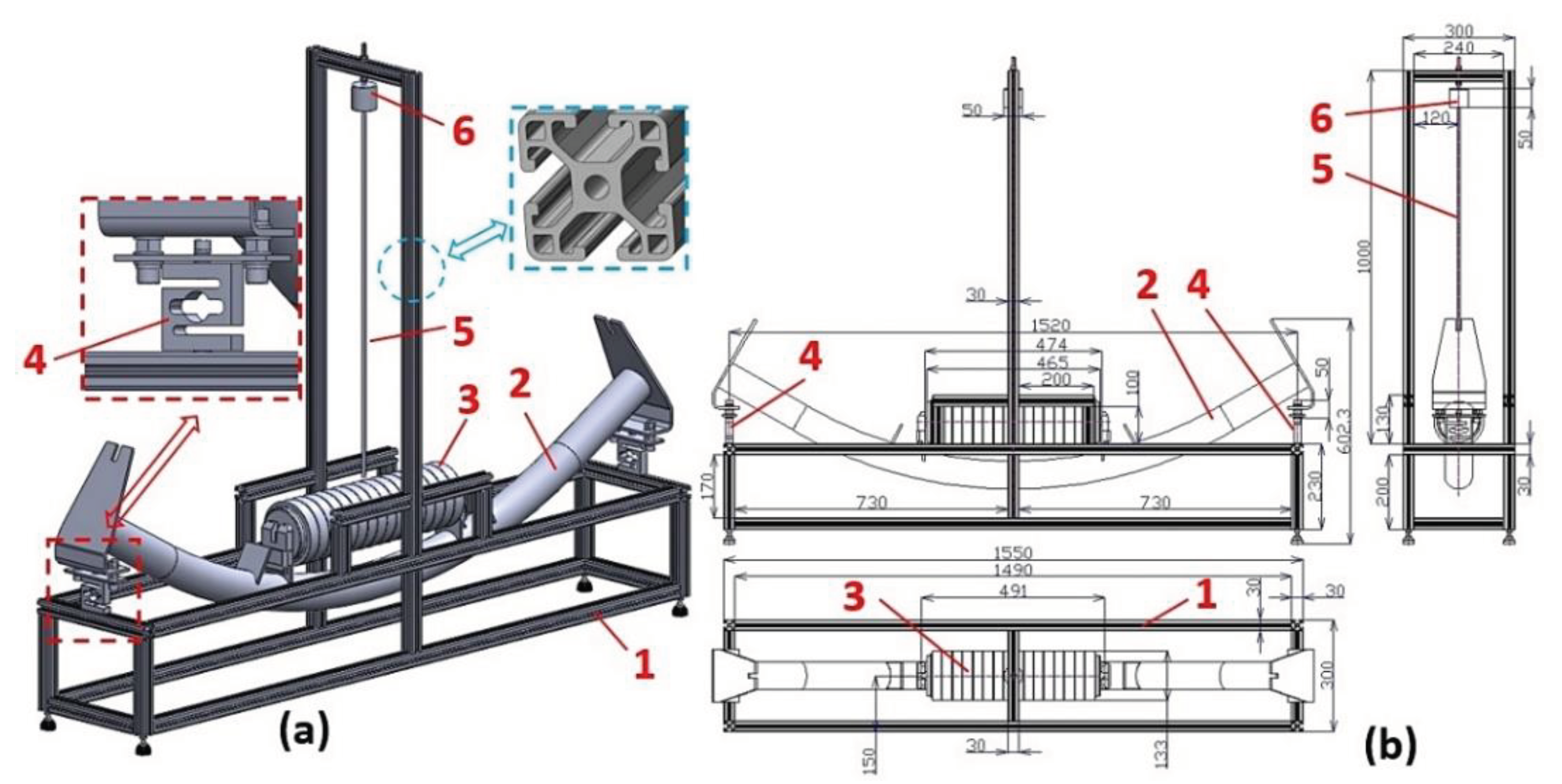
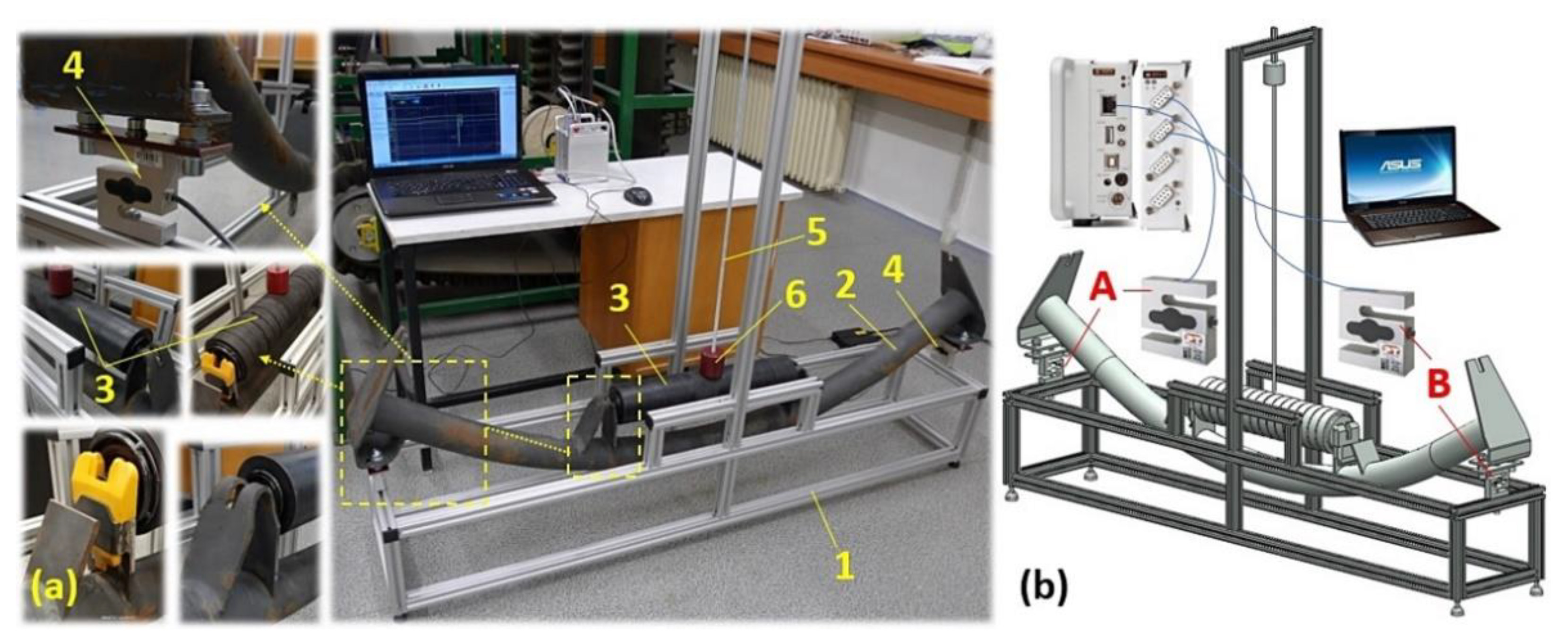
2.1. Laboratory device detecting the forces of grains impacting on the impact roller
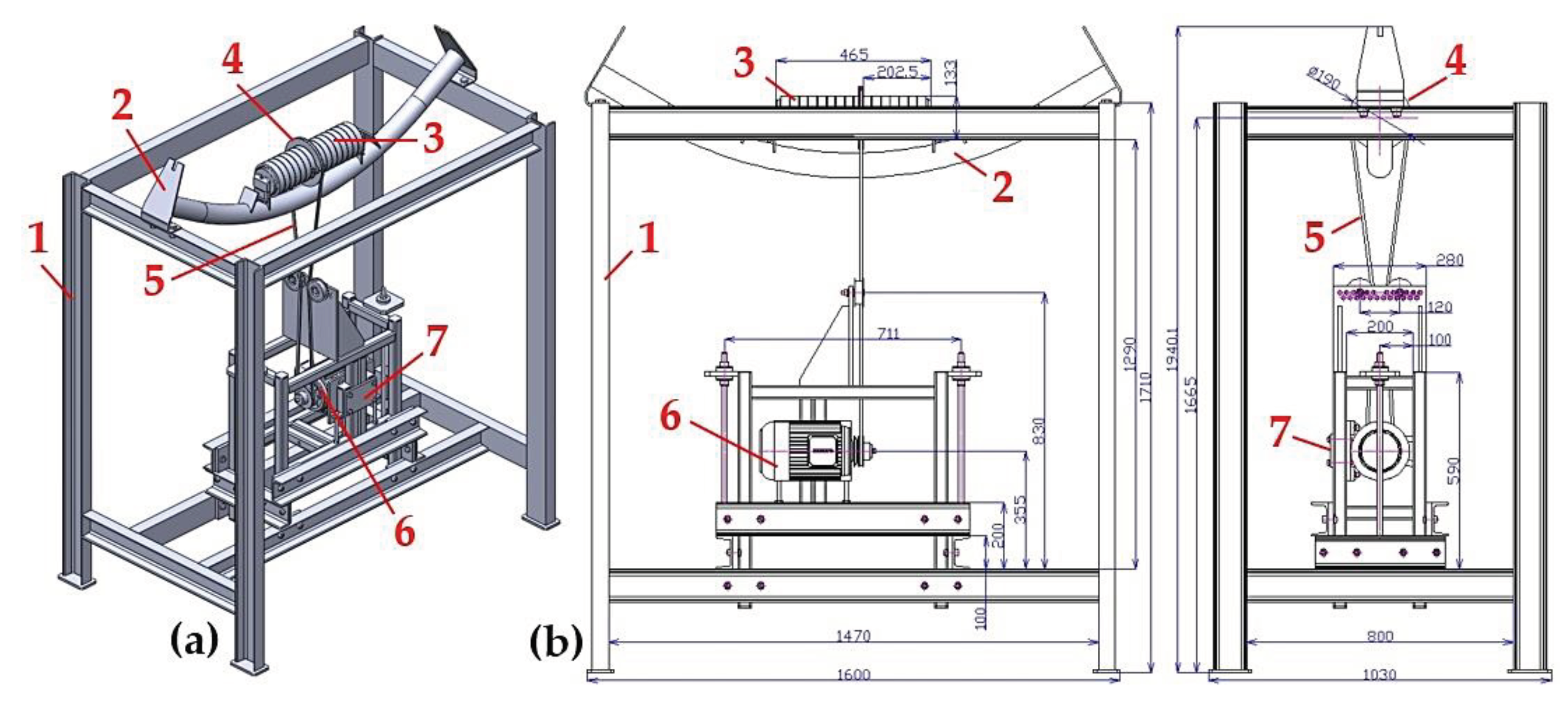
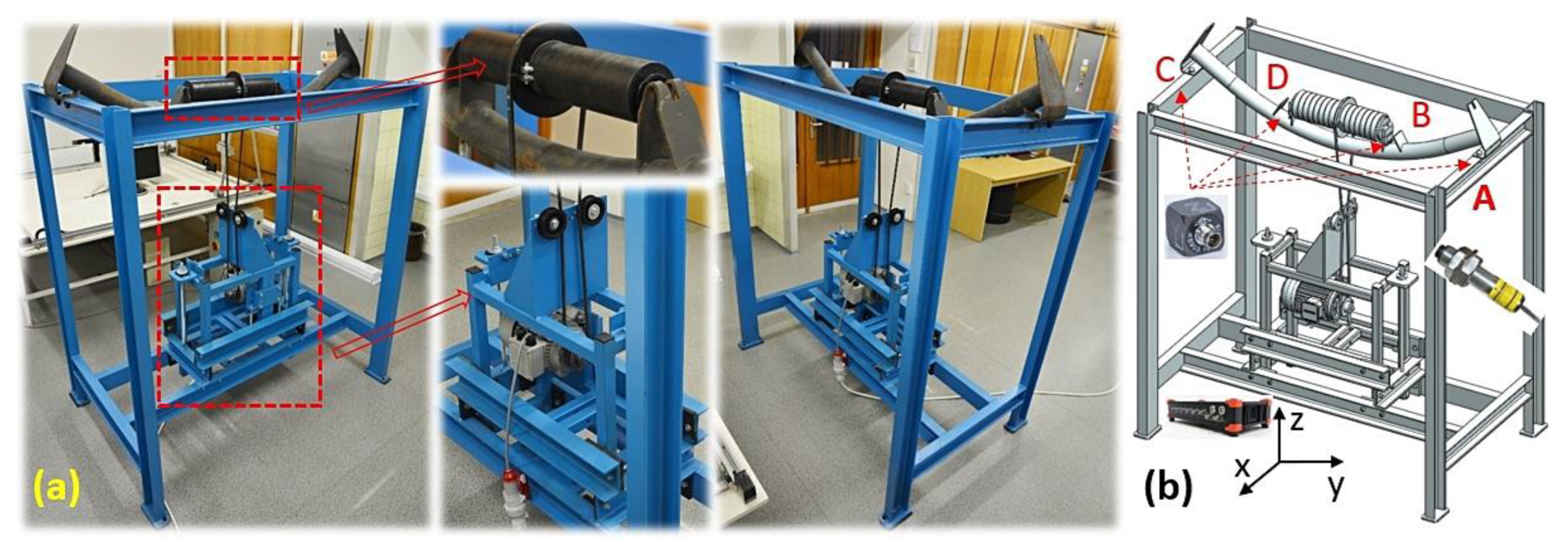
2.2. Laboratory device for detecting the vibration of a rotating impact roller

| Dr [mm] | 89 | 108 | ||||
| vr [m·s-1] |
fi [Hz] |
nr [s-1] |
nr [min-1] |
fi [Hz] |
nr [s-1] |
nr [min-1] |
| 3.15 | 41.28 | 11.27 | 675.96 | 38.55 | 9.28 | 557.04 |
| 2.50 | 32.76 | 8.94 | 536.48 | 30.59 | 7.37 | 442.10 |
| 1.25 | 16.38 | 4.47 | 268.24 | 15.30 | 3.68 | 221.05 |

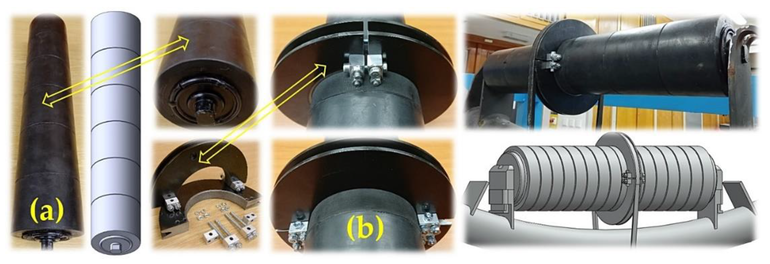
2.1. Impact rollers
3. Results
3.1. Measurement of the force in the supports of a conveyor idler for a weight falling on the casing of an impact roller. Placement of the roller axle in the plastic brackets
| Dr [mm] | 108 | |||||||||
| F0(Dr)j,i [N] | Measurement point “j” | F(Dr)j,i [N] | Measurement point “j” | F(Dr)j,i - F0(Dr)j,i | ||||||
| “A“ | “B“ | “A“ | “B“ | “A“ | “B“ | |||||
| 124.0 | 127.9 | 188.4 | 192.5 | 64.4 | 64.6 | |||||
| 123.8 | 127.9 | 186.3 | 192.8 | 62.5 | 64.9 | |||||
| 123.5 | 127.7 | 174.5 | 178.8 | 51.0 | 51.1 | |||||
| 123.8 1 | 127.9 1 | 193.5 2 | 198.9 2 | 69.7 | 71.0 | |||||
| 123.5 | 127.9 | 179.6 | 187.5 | 56.1 | 59.6 | |||||
| Fd(Dr)j [N] | 60.7 | 62.2 | ||||||||
| κα,j [N] | 10.0 | 9.6 | ||||||||
3.2. Measurement of the force in the supports of a fixed conveyor idler of a weight falling on the conveyor roller casing. Placement of the roller axle in the steel trestles.
| Dr [mm] | 89 | |||||||||
| F0(Dr)j,i [N] | Measurement point “j” | F(Dr)j,i [N] | Measurement point “j” | F(Dr)j,i - F0(Dr)j,i | ||||||
| “A“ | “B“ | “A“ | “B“ | “A“ | “B“ | |||||
| 114.9 | 122.5 | 201.6 | 219.6 | 86.7 | 90.1 | |||||
| 114.8 | 129.5 | 200.5 | 218.4 | 85.7 | 88.9 | |||||
| 114.8 | 129.6 | 203.2 | 219.9 | 88.4 | 90.3 | |||||
| 115.3 1 | 130.3 1 | 201.7 2 | 218.5 2 | 86.4 | 88.2 | |||||
| 117.0 | 131.4 | 202.4 | 218.8 | 85.4 | 87.4 | |||||
| Fd(Dr)j [N] | 86.5 | 89.0 | ||||||||
| κα,j [N] | 1.4 | 1.7 | ||||||||
3.3. Vibration measurement of the rotating rubberized impact roller casing, steel roller axle bracket.
| fi | nr | vr | Measurement point “C“ | Measurement point “D“ | ||||
| v(x)RMS(fi) | v(y)RMS(fi) | v(z)RMS(fi) | v(x)RMS(fi) | v(y)RMS(fi) | v(z)RMS(fi) | |||
| [Hz] | [min-1] | [m·s-1] | [mm·s-1] | [mm·s-1] | ||||
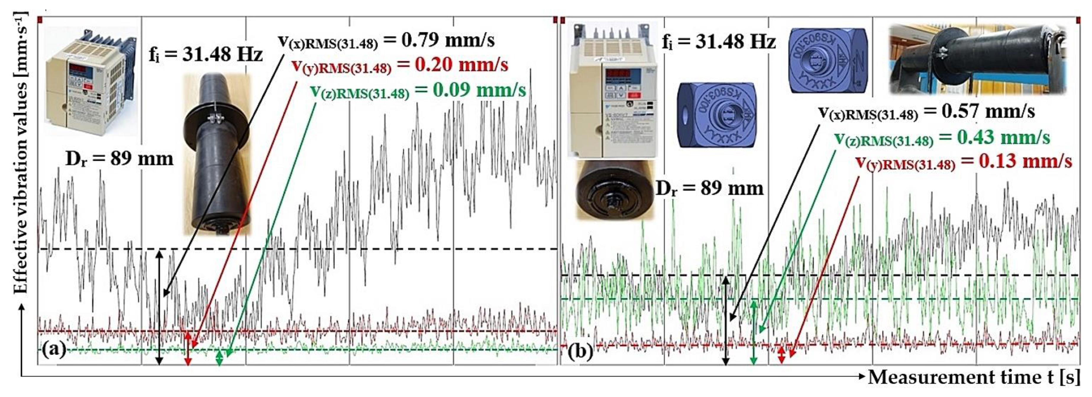
| 39.82 | 677 | 3.15 | 0.44 | 0.21 | 0.10 | 0.54 | 0.11 | 0.62 |
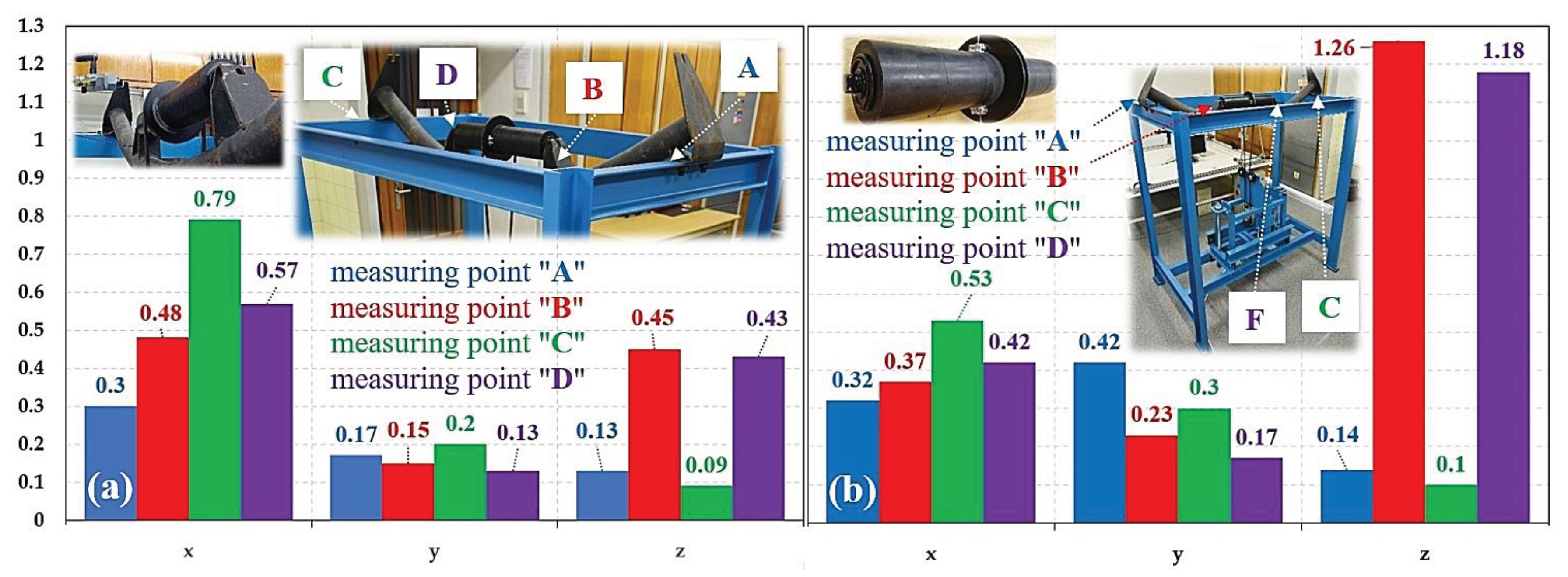
| 31.48 | 535 | 2.49 | 0.79 1 | 0.20 1 | 0.09 1 | 0.57 2 | 0.13 2 | 0.43 2 |
| 15.78 | 268 | 1.25 | 0.15 | 0.09 | 0.07 | 0.17 | 0.08 | 0.16 |
| fi | nr | vr | Measurement point “A“ | Measurement point “B“ | ||||
| v(x)RMS(fi) | v(y)RMS(fi) | v(z)RMS(fi) | v(x)RMS(fi) | v(y)RMS(fi) | v(z)RMS(fi) | |||
| [Hz] | [min-1] | [m·s-1] | [mm·s-1] | [mm·s-1] | ||||
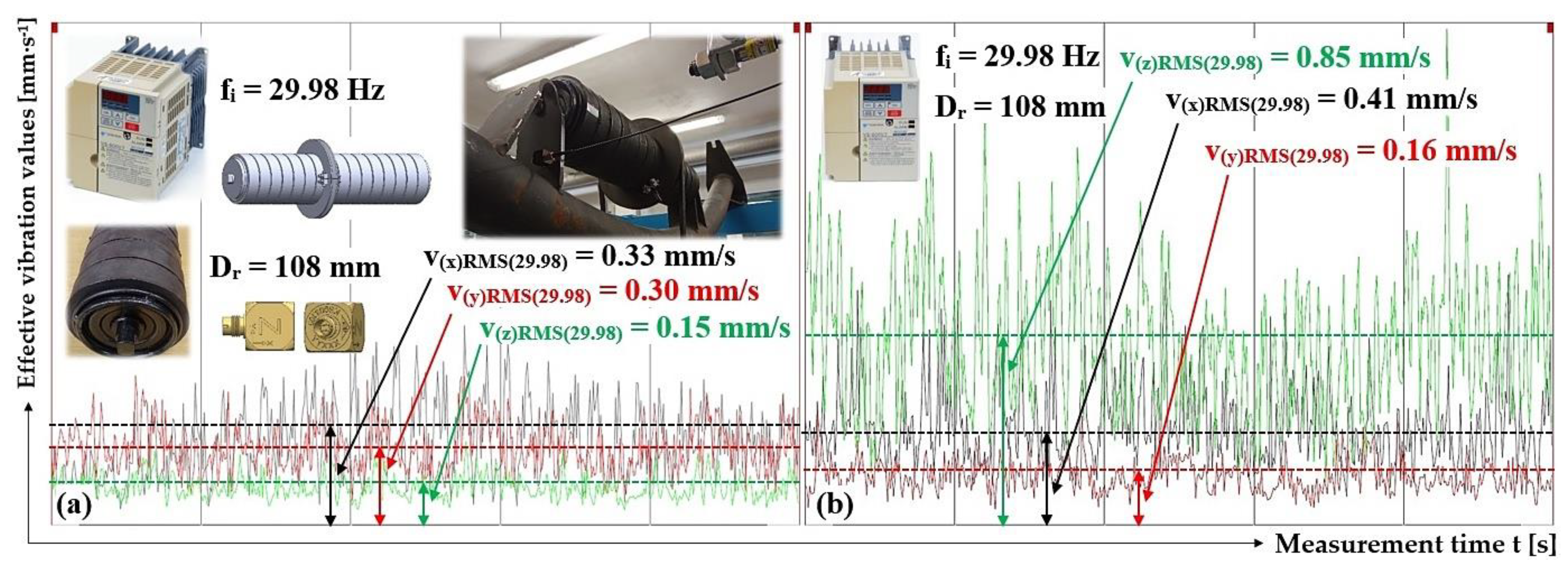
| 37.72 | 559 | 3.16 | 0.38 | 0.32 | 0.18 | 0.56 | 0.20 | 0.92 |
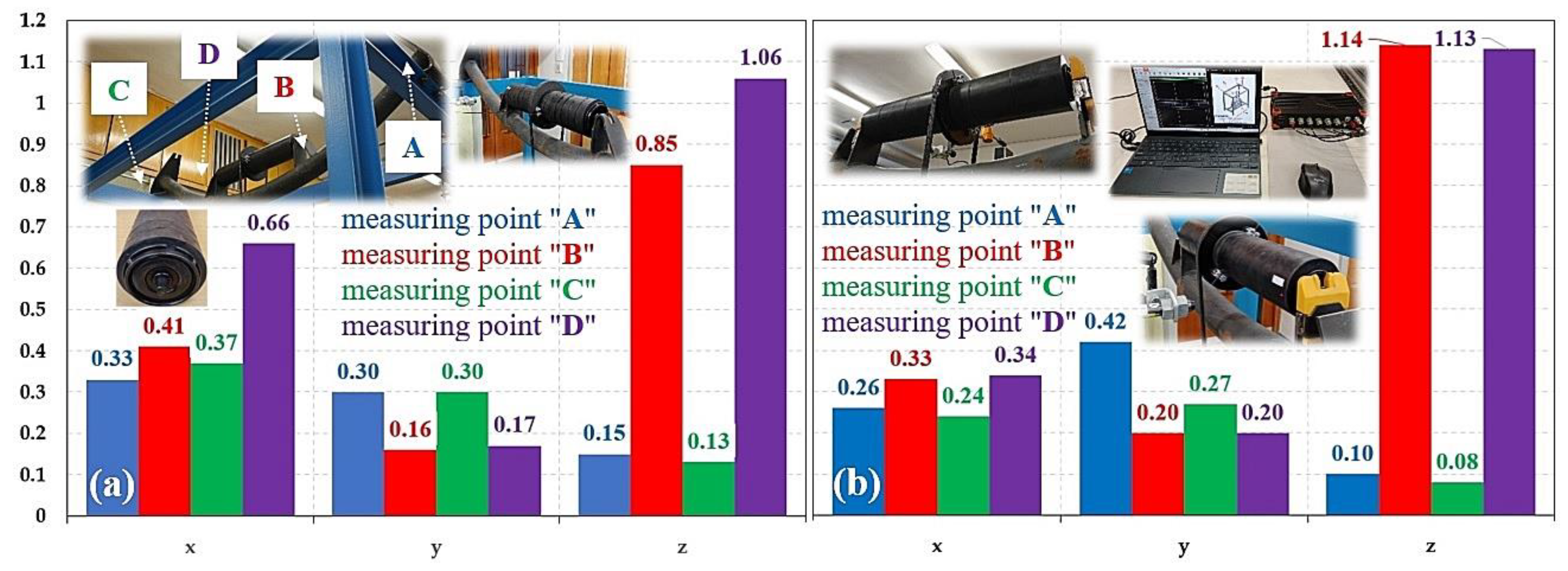
| 29.98 | 444 | 2.51 | 0.33 1 | 0.30 1 | 0.15 1 | 0.41 2 | 0.16 2 | 0.85 2 |
| 14.96 | 222 | 1.25 | 0.10 | 0.15 | 0.08 | 0.16 | 0.10 | 0.36 |
| fi | nr | vr | Measurement point “C“ | Measurement point “D“ | ||||
| v(x)RMS(fi) | v(y)RMS(fi) | v(z)RMS(fi) | v(x)RMS(fi) | v(y)RMS(fi) | v(z)RMS(fi) | |||
| [Hz] | [min-1] | [m·s-1] | [mm·s-1] | [mm·s-1] | ||||
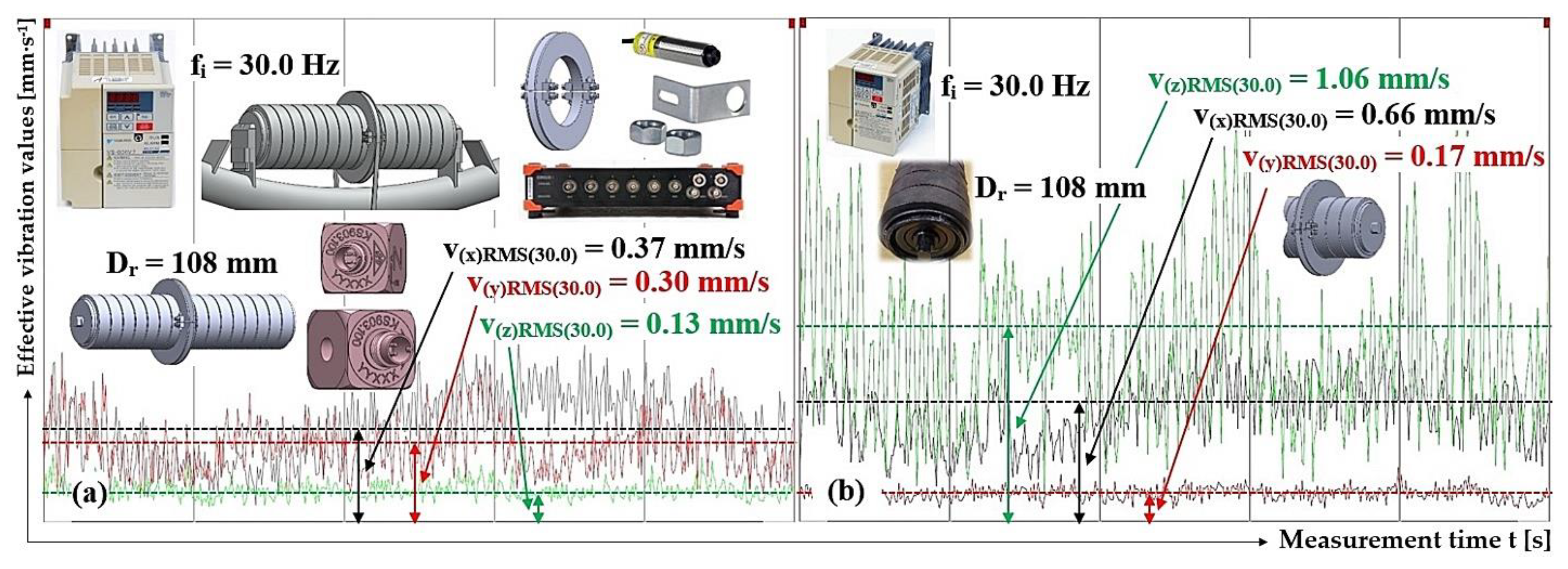
| 37.73 | 559 | 3.16 | 0.35 | 0.33 | 0.13 | 0.72 | 0.21 | 1.06 |
| 30.00 | 444 | 2.51 | 0.37 | 0.30 | 0.13 | 0.66 | 0.17 | 1.06 |
| 14.97 | 222 | 1.25 | 0.12 | 0.14 | 0.08 | 0.20 | 0.10 | 0.37 |
3.4. Vibration measurement of the rotating rubberized impact roller casing, plastic roller axle bracket.
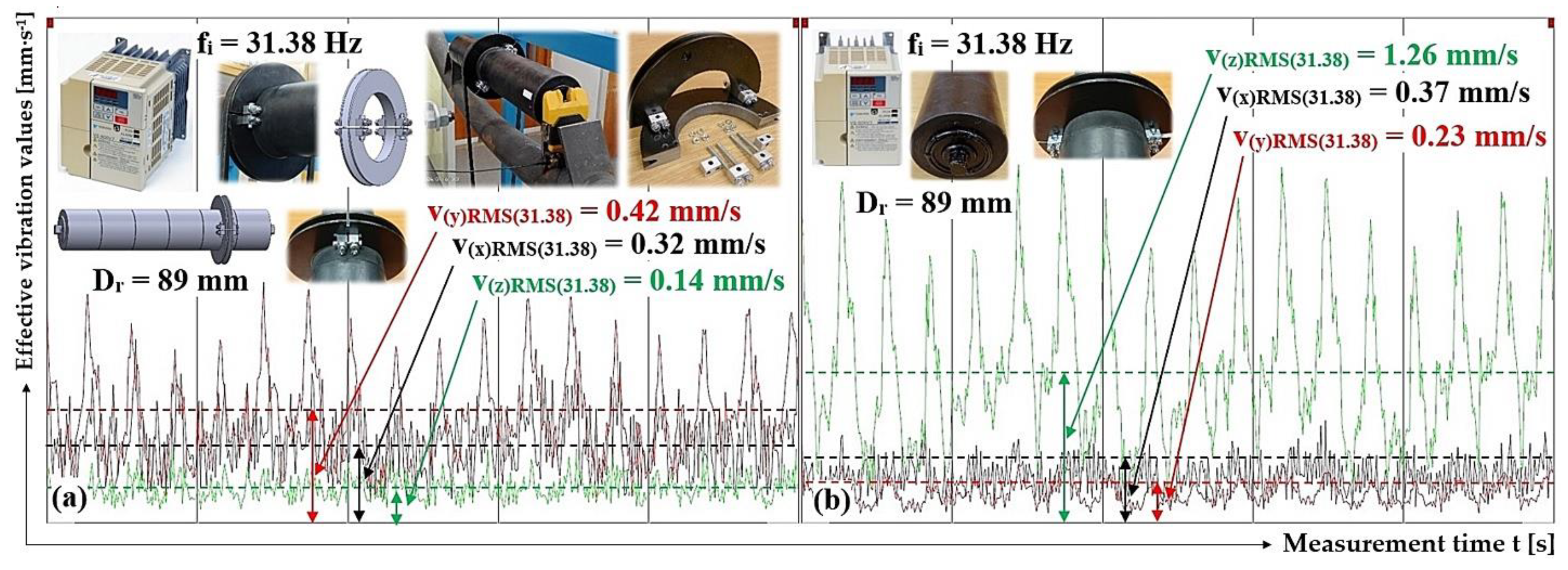
| fi | nr | vr | Measurement point “C“ | Measurement point “D“ | ||||
| v(x)RMS(fi) | v(y)RMS(fi) | v(z)RMS(fi) | v(x)RMS(fi) | v(y)RMS(fi) | v(z)RMS(fi) | |||
| [Hz] | [min-1] | [m·s-1] | [mm·s-1] | [mm·s-1] | ||||
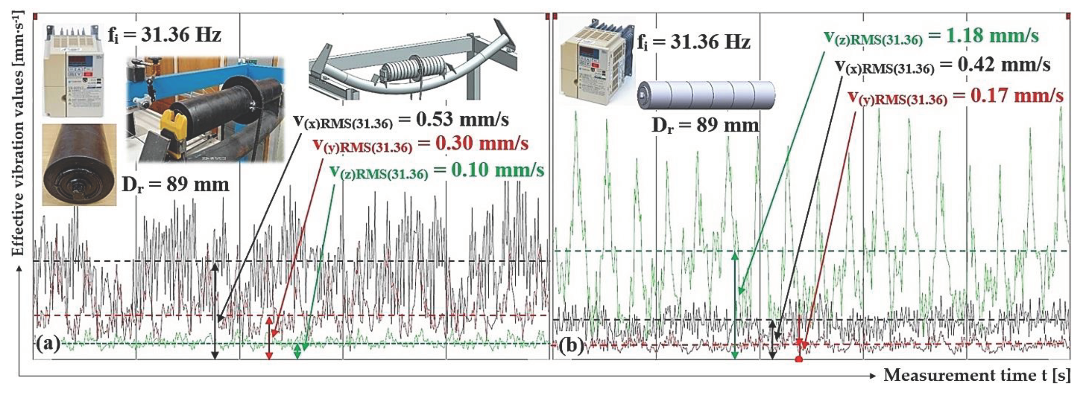
| 39.56 | 672 | 3.13 | 0.32 | 0.49 | 0.10 | 0.44 | 0.19 | 1.98 |
| 31.36 | 533 | 2.48 | 0.53 1 | 0.30 1 | 0.10 1 | 0.42 2 | 0.17 2 | 1.18 2 |
| 15.70 | 267 | 1.24 | 0.19 | 0.14 | 0.06 | 0.20 | 0.10 | 0.43 |
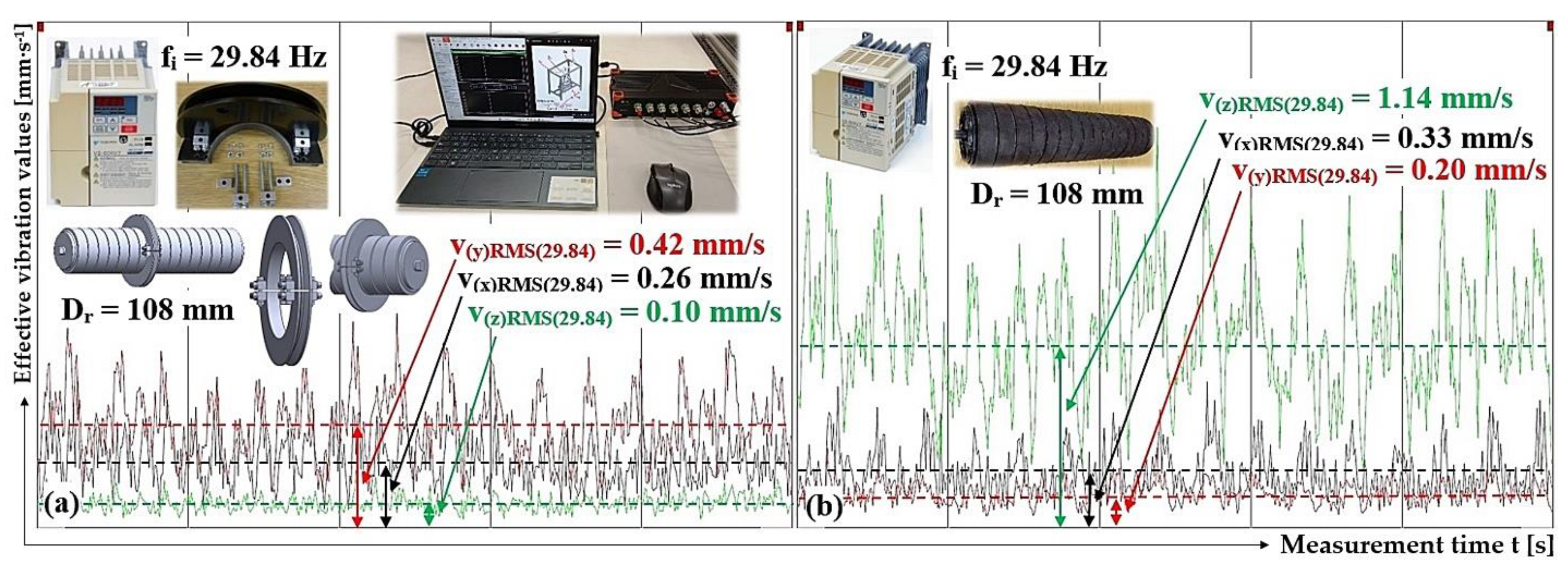
| fi | nr | vr | Measurement point “A“ | Measurement point “B“ | ||||
| v(x)RMS(fi) | v(y)RMS(fi) | v(z)RMS(fi) | v(x)RMS(fi) | v(y)RMS(fi) | v(z)RMS(fi) | |||
| [Hz] | [min-1] | [m·s-1] | [mm·s-1] | [mm·s-1] | ||||
| 37.62 | 557 | 3.15 | 0.73 | 0.57 | 0.22 | 0.71 | 0.48 | 1.20 |
| 29.84 | 442 | 2.50 | 0.26 1 | 0.42 1 | 0.10 1 | 0.33 2 | 0.20 2 | 1.14 2 |
| 14.87 | 220 | 1.25 | 0.11 | 0.18 | 0.07 | 0.20 | 0.10 | 0.46 |
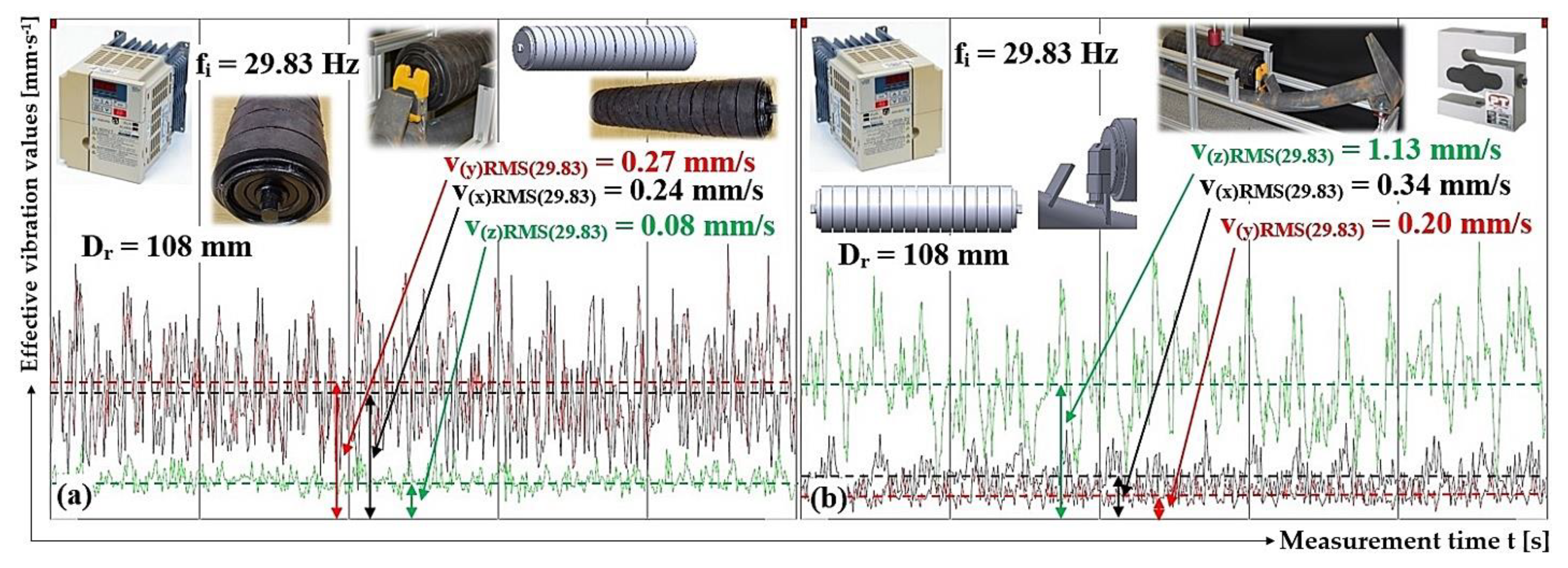
| fi | nr | vr | Measurement point “C“ | Measurement point “D“ | ||||
| v(x)RMS(fi) | v(y)RMS(fi) | v(z)RMS(fi) | v(x)RMS(fi) | v(y)RMS(fi) | v(z)RMS(fi) | |||
| [Hz] | [min-1] | [m·s-1] | [mm·s-1] | [mm·s-1] | ||||
| 37.62 | 557 | 3.15 | 0.77 | 0.43 | 0.10 | 0.66 | 0.65 | 1.22 |
| 29.83 | 442 | 2.50 | 0.24 | 0.27 | 0.08 | 0.34 | 0.20 | 1.13 |
| 14.86 | 220 | 1.24 | 0.11 | 0.12 | 0.05 | 0.21 | 0.13 | 0.46 |
4. Discussion
5. Conclusions
Author Contributions
Funding
Data Availability Statement
Conflicts of Interest
References
- Rozbroj, J.; Necas, J.; Gelnar, D.; Hlosta, J.; Zegzulka, J. Validation of movement over a belt conveyor drum. Advances in Science and Technology. Research Journal 2017, 11, 118–124. [Google Scholar] [CrossRef]
- Fedorko, G.; Molnar, V.; Grincova, A.; Dovica, M.; Toth, T.; Husakova, N.; Kelemen, M. Failure analysis of irreversible changes in the construction of rubber–textile conveyor belt damaged by sharp-edge material impact. Engineering Failure Analysis 2014, 39, 135–148. [Google Scholar] [CrossRef]
- Andrejiova, M.; Grincova, A. Klasifikace poškození nárazem na pryžotextilním dopravním pásu metodou Naïve-Bayes. Wear 2018, 414, 59–67. [Google Scholar] [CrossRef]
- Fedorko, G.; Molnar, V.; Zivcak, J.; Dovica, M.; Husakova, N. Analýza poruch textilního pryžového dopravního pásu poškozeného dynamickým opotřebením. Analýza selhání techniky 2013, 28, 103–114. [Google Scholar]
- Andrejiova, M.; Grincova, A.; Marasova, D. Identification with machine learning techniques of a classification model for the degree of damage to rubber-textile conveyor belts with the aim to achieve sustainability. Engineering Failure Analysis 2021, 127, 105564. [Google Scholar] [CrossRef]
- Alviari, L. P.; Anggamawarti, M. F.; Sanjiwani, Y.; Risonarta, V. Y. Classification of impact damage on a rubber-textile conveyor belt: A review. International Journal of Mechanical Engineering Technologies and Applications 2020, 1, 21–27. [Google Scholar] [CrossRef]
- Bortnowski, P.; Kawalec, W.; Krol, R.; Ozdoba, M. Types and causes of damage to the conveyor belt–Review, classification and mutual relations. Engineering Failure Analysis 2022, 140, 106520. [Google Scholar] [CrossRef]
- Hicke, K.; Hussels, M. T.; Eisermann, R.; Chruscicki, S.; Krebber, K. Distributed Fibre Optic Acoustic and Vibration Sensors for Industrial Monitoring Applications. In Proceedings AMA Conferences 2017 with SENSOR and IRS2 (pp. 274-279). AMA Service GmbH.
- Liu, Y.; Miao, C.; Li, X.; Ji, J.; Meng, D.; Wang, Y. A Dynamic Self-Attention-Based Fault Diagnosis Method for Belt Conveyor Idlers. Machines 2023, 11, 216. [Google Scholar] [CrossRef]
- Vasic, M.; Stojanovic, B.; Blagojevic, M. Failure analysis of idler roller bearings in belt conveyors. Engineering Failure Analysis 2020, 117, 104898. [Google Scholar] [CrossRef]
- Soares, J. L.; Costa, T. B.; Moura, L. S.; Sousa, W. S.; Mesquita, A. L.; Mesquita, D. S. Machine Learning Based Fault Detection on Belt Conveyor Idlers.
- Gondek, H.; Kolman, J.; Bohac, D. Results of belt conveyors noise reduction with the construction of roller holders. International Multidisciplinary Scientific GeoConference: SGEM 2022, 22, 369–376. [Google Scholar]
- Kolman, J.; Bohac, D. Noise reduction of belt conveyor tracks. International Multidisciplinary Scientific GeoConference: SGEM 2020, 20, 195–202. [Google Scholar]
- Shiri, H.; Wodecki, J.; Ziętek, B.; Zimroz, R. Inspection robotic UGV platform and the procedure for an acoustic signal-based fault detection in belt conveyor idler. Energies 2021, 14, 7646. [Google Scholar] [CrossRef]
- Perun, G. Attempt to evaluate the technical condition of the rollers of the belt conveyor by vibration measurements. Vibroengineering Procedia 2014, 3, 296–299. [Google Scholar]
- Alharbi, F.; Luo, S.; Zhang, H.; Shaukat, K.; Yang, G.; Wheeler, C. A.; Chen, Z. A brief review of acoustic and vibration signal-based fault detection for belt conveyor idlers using machine learning models. Sensors 2023, 23, 1902. [Google Scholar] [CrossRef] [PubMed]
- Liu, X.; Pang, Y.; Lodewijks, G.; He, D. Experimental research on condition monitoring of belt conveyor idlers. Measurement 2018, 127, 277–282. [Google Scholar] [CrossRef]
- Ji, Y.; Ma, J.; Zhou, Z.; Li, J.; Song, L. Dynamic Yarn-Tension Detection Using Machine Vision Combined with a Tension Observer. Sensors 2023, 23, 3800. [Google Scholar] [CrossRef]
- Staab, H.; Botelho, E.; Lasko, D. T.; Shah, H.; Eakins, W.; Richter, U. A robotic vehicle system for conveyor inspection in mining. In 2019 IEEE International Conference on Mechatronics (ICM) 2019, Vol. 1, pp. 352–357). IEEE.
- Roos, W. A.; Heyns, P. S. In-belt vibration monitoring of conveyor belt idler bearings by using wavelet package decomposition and artificial intelligence. International Journal of Mining and Mineral Engineering 2021, 12, 48–66. [Google Scholar] [CrossRef]
- Bortnowski, P.; Krol, R.; Ozdoba, M. Roller damage detection method based on the measurement of transverse vibrations of the conveyor belt. Eksploatacja i Niezawodność 2022, 24. [Google Scholar] [CrossRef]
- Hliníkový profil 30×30 B8. Available online: https://www.marek.eu/hlinikove-konstrukcni-profily-mi-system/serie-b/velikost-30-drazka-b8/37496/hlinikovy-profil-30x30-b8.html (accessed on 26 September 2021).
- AST tenzometrický snímač síly. Available online: https://www.format1.cz/files/products_files/a/AST.pdf (accessed on 16 February 2023).
- Technical reference manual DS-NET. Available online: https://d36j349d8rqm96.cloudfront.net/3/6/Dewesoft-DS-NET-Manual-EN.pdf (accessed on 28 October 2023).
- VS-606V7 Series Instruction manual. Available online: https://automasjonslab.files.wordpress.com/2018/09/yaskawa-607.pdf (accessed on 25 June 2020).
- Hrabovsky, L.; Pravda, S.; Sebesta, R.; Novakova, E.; Kurac, D. Detection of a Rotating Conveyor Roller Casing Vibrations on a Laboratory Machine. Symmetry 2023, 15, 1626. [Google Scholar] [CrossRef]
- Hrabovsky, L.; Novakova, E.; Pravda, S.; Kurac, D.; Machalek, T. The Reduction of Rotating Conveyor Roller Vibrations by the Use of Plastic Brackets. Preprints 2023, 2023111342. [Google Scholar] [CrossRef]
- Klínové řemenice. Available online: https://www.pikron.cz/getmedia/0821cabe-83bf-41de-abbd-bdca4f34702d/PIKRON-klinove-remenice.pdf (accessed on 18 March 2023).
- Hand-Arm Acceleration Sensor KS903.10. Available online: https://www.pce-instruments.com/eu/pce-instruments-hand-arm-acceleration-sensor-ks903.10-det_5966162.htm (accessed on 8 December 2022).
- Instruction Manual ROLS / ROLS24 Remote Optical Laser Sensor. Available online: https://monarchserver.com/Files/pdf/1071-4851-118_ROLS_ROLS24_Manual.pdf (accessed on 3 Jul 2023).
- DEWESoft General catalog. Available online: https://www.datocms-assets.com/53444/1667943193-dewesoft-product-catalog-en.pdf (accessed on 2 May 2021).
- ČSN ISO 10816-1: Mechanical vibration - Evaluation of machine vibration by measurements on non-rotating parts - Part 1: General guidelines (In Czech: Vibrace - Hodnocení vibrací strojů na základě měření na nerotujících částech -Část 1: Všeobecné směrnice). Available online: https://www.technicke-normy-csn.cz/csn-iso-10816-1-011412-158753.html (accessed on 17 September 2022).
- Madr, V.; Knejzlik, J.; Kopecny, I.; Novotny, I. Fyzikální Měření (In English: Physical Measurement); SNTL: Czech Republic, 1991; p. 304. ISBN 80-03-00266-41.
- Michalik, P.; Dobransky, J.; Hrabovsky, L.; Petrus, M. Assessment of the manufacturing possibility of thin-walled robotic portals for conveyance workplaces. Advances in Science and Technology. Research Journal 2018, 12. [Google Scholar]
- Wang, R.; Cheung, C. F.; Wang, C. Unsupervised Defect Segmentation in Selective Laser Melting. IEEE Transactions on Instrumentation and Measurement 2023. [Google Scholar] [CrossRef]








| Dr [mm] | 89 | |||||||||
| F0(Dr)j,i [N] | Measurement point “j” | F(Dr)j,i [N] | Measurement point “j” | F(Dr)j,i - F0(Dr)j,i | ||||||
| “A“ | “B“ | “A“ | “B“ | “A“ | “B“ | |||||
| 119.3 | 122.8 | 202.9 | 208.2 | 83.6 | 85.4 | |||||
| 119.4 | 123.0 | 202.7 | 207.6 | 83.3 | 84.6 | |||||
| 119.1 | 122.9 | 203.5 | 209.8 | 84.1 | 86.9 | |||||
| 119.4 1 | 123.0 1 | 204.8 2 | 210.4 2 | 85.7 | 87.4 | |||||
| 119.6 | 123.6 | 201.9 | 206.9 | 82.3 | 83.3 | |||||
| Fd(Dr)j [N] | 83.8 | 85.5 | ||||||||
| κα,j [N] | 1.5 | 2.3 | ||||||||
| Dr [mm] | 108 | |||||||||
| F0(Dr)j,i [N] | Measurement point “j” | F(Dr)j,i [N] | Measurement point “j” | F(Dr)j,i - F0(Dr)j,i | ||||||
| “A“ | “B“ | “A“ | “B“ | “A“ | “B“ | |||||
| 119.4 | 134.3 | 187.2 | 203.1 | 67.8 | 68.8 | |||||
| 119.8 | 134.7 | 190.9 | 207.2 | 71.1 | 72.5 | |||||
| 121.3 | 136.1 | 190.2 | 206.9 | 68.9 | 70.8 | |||||
| 120.8 1 | 135.8 1 | 195.6 2 | 209.1 2 | 74.8 | 73.3 | |||||
| 120.1 | 135.0 | 199.4 | 214.0 | 79.3 | 79.0 | |||||
| Fd(Dr)j [N] | 72.4 | 72.9 | ||||||||
| κα,j [N] | 6.5 | 4.6 | ||||||||
| fi | nr | vr | Measurement point “A“ | Measurement point “B“ | ||||
| v(x)RMS(fi) | v(y)RMS(fi) | v(z)RMS(fi) | v(x)RMS(fi) | v(y)RMS(fi) | v(z)RMS(fi) | |||
| [Hz] | [min-1] | [m·s-1] | [mm·s-1] | [mm·s-1] | ||||
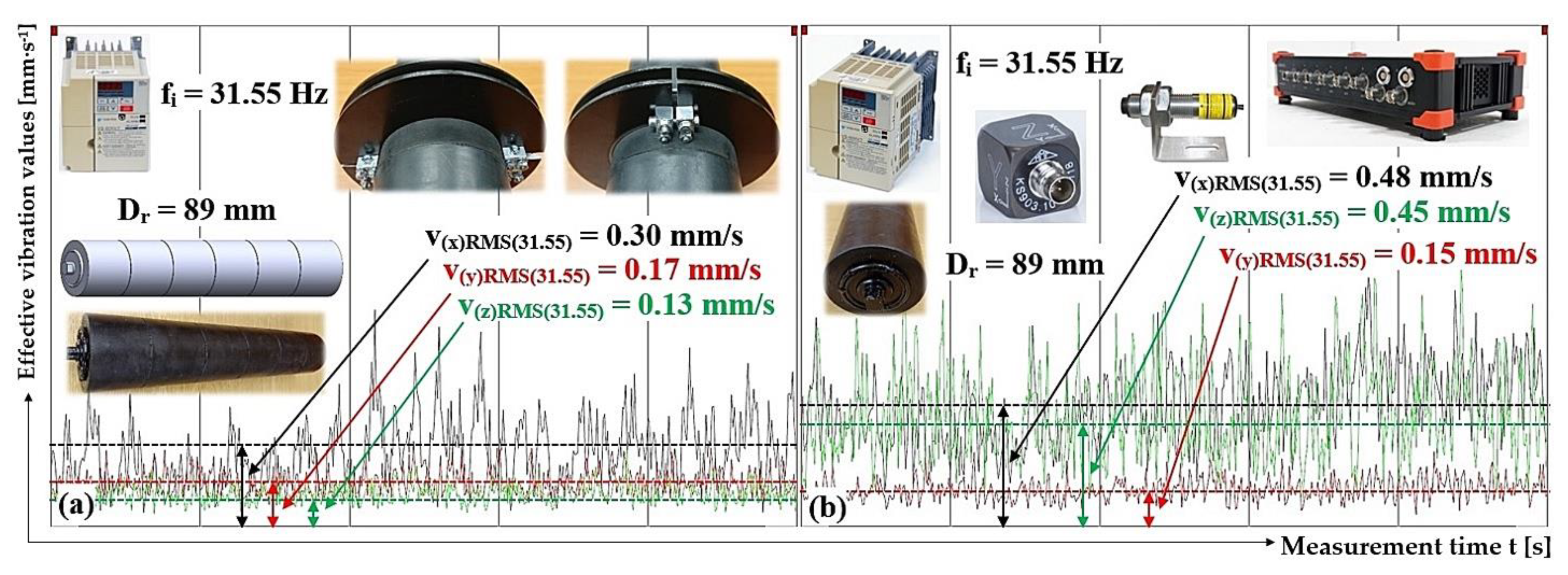
| 39.84 | 677 | 3.16 | 0.21 | 0.20 | 0.12 | 0.47 | 0.13 | 0.57 |
| 31.55 | 536 | 2.50 | 0.30 1 | 0.17 1 | 0.13 1 | 0.48 2 | 0.15 2 | 0.45 2 |
| 16.28 | 268 | 1.25 | 0.15 | 0.10 | 0.08 | 0.19 | 0.07 | 0.16 |
| fi | nr | vr | Measurement point “A“ | Measurement point “B“ | ||||
| v(x)RMS(fi) | v(y)RMS(fi) | v(z)RMS(fi) | v(x)RMS(fi) | v(y)RMS(fi) | v(z)RMS(fi) | |||
| [Hz] | [min-1] | [m·s-1] | [mm·s-1] | [mm·s-1] | ||||
| 39.64 | 674 | 3.14 | 0.34 | 0.61 | 0.13 | 0.45 | 0.31 | 1.91 |
| 31.38 | 533 | 2.49 | 0.32 1 | 0.42 1 | 0.14 1 | 0.37 2 | 0.23 2 | 1.26 2 |
| 15.72 | 267 | 1.24 | 0.14 | 0.19 | 0.07 | 0.17 | 0.12 | 0.53 |
Disclaimer/Publisher’s Note: The statements, opinions and data contained in all publications are solely those of the individual author(s) and contributor(s) and not of MDPI and/or the editor(s). MDPI and/or the editor(s) disclaim responsibility for any injury to people or property resulting from any ideas, methods, instructions or products referred to in the content. |
© 2024 by the authors. Licensee MDPI, Basel, Switzerland. This article is an open access article distributed under the terms and conditions of the Creative Commons Attribution (CC BY) license (http://creativecommons.org/licenses/by/4.0/).


