1. Introduction
The constant pressure to reduce costs, increasingly shorter product life cycles, and their miniaturization, integration of various functions, and sophistication – are some of the innovation trends manifested in most industries. These trends represent a challenge for designing and modeling flexible, reliable, and economical production cells, workplaces, and operations. [
1]
Systems for intelligent production, such as Digital Factory and Virtual Factory, are changing sectors and business models. These systems offer cutting-edge ideas and technology that boost productivity, cut expenses, and boost competitiveness. Production flexibility, data digitalization, data integration, predictive maintenance, downtime minimization, prospective virtual model development, and production flexibility are the primary areas that these systems impact. [
2,
3]
There is a strong and optimistic sentiment regarding intelligent production systems, Digital Factory, and Virtual Factory. These creative manufacturing techniques are now important pillars of the digital revolution and the industrial transformation. The evolution of innovation, meeting and overcoming new obstacles, globalization and connectivity, and strategic competitiveness are a few significant facets of the state of intelligent industrial systems today. [
4]
At the University of Zilina, situated within the Faculty of Mechanical Engineering, and specifically at our Department of Industrial Engineering, we are deeply engaged in the study and implementation of digital and virtual factories on a significant scale. Within our facility, we are equipped with various laboratories, including the Laboratory for Designing Production and Assembly Systems, where a portion of our research endeavors take place. This laboratory is dedicated to the exploration and application of emerging Industry 4.0 and Industry 5.0 technologies in both educational and research contexts. Utilizing simulation and modeling software, students and researchers actively engage with virtual and augmented reality environments, particularly focusing on workplace design and data acquisition methodologies. Additionally, our utilization of virtual factories facilitates the assessment of production quality and the collection of statistical data pertinent to process evaluation.
Students and researchers operate within both 2D and 3D spatial domains. As depicted in
Figure 1a, virtual reality tools are utilized for the creation of immersive training simulations.
Figure 1b illustrates the technology enabling workplace design and subsequent virtual verification, with potential applications extending to employee training initiatives.
Figure 1c showcases a programmed robotic workstation utilized by researchers and students to model entire workplace scenarios and monitor requisite actions. This workstation is integrated within a production line where manufacturing and assembly processes are scrutinized—a focal area of research within the Department of Industrial Engineering.
In these operational environments, researchers leverage the Real-Time Location System (RTLS) to facilitate the real-time tracking of personnel or vehicles. This technology enables precise monitoring of entry points and the trajectory of movements over time, leveraging Radio Frequency Identification Tags for its functionality. Furthermore, our research employs various software platforms, including Tecnomatix Plant Simulation, Visual Component, and others. For immersive virtual experiences, hardware such as Oculus Quest 2, HTC Vive Pro, HoloLens 2, and 3 are extensively utilized within the virtual factory setting.
In summary, the evolution of contemporary manufacturing processes can be attributed in large part to intelligent production systems like Digital Factory and Virtual Factory. From improved efficiency and flexibility to improved risk prediction and mitigation in the sector, these technologies provide several advantages. Positive views are held of intelligent production systems, the virtual factory, and the digital factory. These technologies are becoming indispensable for companies looking to boost their efficiency, become more competitive, and adapt better to the changing dynamics of the market. [
5]
2. Literature Review
The literature study that follows illustrates the variety of interests that need to be considered in this scenario.
An intelligent production system can autonomously adjust to unforeseen events, such as shifting market demands, technological advancements, or societal demands. Such a response needs to fulfill predetermined standards within specific budgetary and timeframes. Intelligent manufacturing systems tend to focus more on the problem's technical components. The systematization of all production elements and their preparation, the flexible integration of the entire enterprise to maximize cooperation between people and intelligent technical means, the adaptability and self-learning of the system, and the openness and expandability of the information are the fundamental characteristics of IMS. [
6] Apart from intelligent production systems, there are also known bionic production systems. These systems are created and planned so that their functioning and activity mimic that of living organic systems, primarily in terms of their spontaneity, dynamism, movement, and harmony. [
7]
Agile production is particularly crucial because it allows manufacturers to react swiftly to changes in the market and new orders. For example, they can often immediately rearrange their production layout to accommodate a new order. Adding value for the client, being adaptable, appreciating people's skills and knowledge, and forming virtual alliances are the four main characteristics of agile manufacturing. [
7]
The production systems are also associated with a virtual and digital factory. The term "digital enterprise" describes an output that is represented virtually rather than physically. This term refers to a scenario in which information and computer technologies are integrated and virtual, computer-generated models take the place of reality. Before real deployment, these virtual solutions allow for the verification of all conflicting circumstances and the suggestion of optimum solutions. The digital enterprise is used to plan, evaluate, simulate, and optimize the creation of complex products. Experts in their fields and seasoned professionals are usually the ones who apply these solutions. Therefore, there is a need for systems that can fully replace these people. The utilization of intelligent technology guarantees the production process's flexibility and independence. An intelligent production system is the next stage of production system evolution. It can gather data from sensors, adapt flexibly to the demands of a large range of manufactured parts, and autonomously reconfigure to altered production conditions. [
8]
The studies conducted by Liu et al. involve remanufacturing. Remanufacturing is one of the best strategies for resolving the issues with the present intelligent production system, claim the authors. Enhancing production and resource efficiency in remanufacturing is also beneficial, as it is a prerequisite for long-term and sustainable development. This study developed an intelligent data-driven control system to increase remanufacturing assembly systems' productivity and resource efficiency. The reassembly scheme's optimization approach is built to reduce complex costs and quality loss. The remanufactured parts are then measured, sorted, and coded by the data processing and acquisition technology, and the dimension chain is computed. Then, to accomplish intelligent control of the refurbishment assembly process, a control approach based on real-time monitoring and dynamic compensation of response to aberrant quality is provided. Furthermore, research and implementation are being done on a few data-oriented intelligent control system technologies, such as dynamic compensation architecture, real-time monitoring, information perception and fusion technology, and so on. Lastly, the engine reconditioning workshop takes advantage of the prototype's intelligent control system. The effectiveness of a data-driven intelligent control system in remanufacturing is demonstrated by both theoretical and experimental results, offering a technique and technical support for production and resource efficiency in remanufacturing systems. [
9]
The efficiency of a complex of collaborative robots within intelligent manufacturing systems is improved, as reported by Gorkavyy et al. in their study. They made sure the control system was intellectualized in this investigation. The potential to enhance the process of modeling the human aspect in the construction of a control law sets this contribution apart from others that suggest similar approaches to improving the efficiency of technological processes based on collaborative robots. An industrial configuration's typical cobot control system model's structure and functional diagram are shown. The inadequacies of the conventional method for formulating regulations governing the motion of a cobot in an arbitrary environment within the same workstation as an individual are illustrated. Proposed are both structural and functional solutions that delineate a plan to enhance the level of synergistic effect between humans and machines. To accomplish the desired outcome, an expanded sensor and analytics system can be implemented, together with an intelligent module designed to create and optimize the robot's movement trajectory in the event of disturbances. The findings of a comparison between an intelligent manufacturing system prototype and a typical cobot control system are given. According to the operation, the collected findings show a considerable time and energy savings of 15% to 182% when employing an intelligent control system. The strengthening of integrative links between intelligent analysis and optimization modules, which permits multimodal real-time processing of sensory data and environmental modeling to anticipate human behaviors and generate cobot reactions, is a defining element of the suggested strategy. [
10]
The design of an intelligent control system for machine assembly is resolved in a Wang et al. publication. Due to its complex design, unstable design, and low design efficiency, the original machine used in this study exhibits flaws. As a result, an intelligent control system founded on building technology was created in this study. This study examines the overall framework design, process design, functional module design, control and detection algorithm, and functional module design of the control system in detail. Next, the assembly machine's basic design and operation will be explained. To guarantee the mounting attitude and control accuracy, the design process and implementation impact of intelligent location control are also discussed. According to the findings of the field test, the control system can direct the installation machine to better carry out the required action and fulfill the intended purpose. Utilizing a control system, the product was assembled with an average assembly time of approximately 38 minutes, which is shorter than the study-determined design time, and an assembly accuracy of ±3mm. [
11]
In the contemporary environment of industrial automation and technological advancement, the problem warrants more examination. This subject has several benefits for industrial development and production methods. Pre-assembly intelligent control system deployment results in more effective production management, improved product quality, accelerated development, and more flexible solutions. Reducing the possibility of human error by automation and monitoring is equally crucial. All things considered, this subject can boost productivity in the industrial sector and lead it toward cutting-edge, competitive, and intelligent production techniques. [
12]
The optimal planning of assembly system layouts for cooperation with human robots is a focus of research conducted by Eswaran et al. This study also addresses visualization using immersive technology. The implementation of novel Industry 4.0 technologies, like virtual reality (VR), augmented reality (AR), and cooperative robots, enhances the accuracy and adaptability of manufacturing processes. The key components of tailored automation are integrated into a collaborative, adaptable manufacturing system that includes both humans and robots while improving worker safety. For a Human-Robot Collaboration (HRC) production system—a common illustration of an intelligent manufacturing system—the proposed work incorporates an AR-assisted assembly layout configuration approach. The need for new variations in the market and the upgrading of new technologies in the current system are taken into consideration when reconfiguring or reconfiguring the assembly layout. To increase manufacturing output while minimizing downtime, allocating resources optimally, and making optimum use of floor space, a multi-objective algorithm is developed. There are three stages to the chosen work: To find appropriate resources (human, robot) for the various assembly tasks in the HRC system, a task assignment approach is first built. The optimization model considers outcomes like resource allocation, resource count, and resource footprint as input. The next step is to use modified particle swarm optimization to design a workable assembly plan for the production system of the HRC. Furthermore, the layout's ideal aisle has been generated as a conveyor using the breadth-first method. Comparative studies were specifically conducted in this paper, allowing an examination of the suggested modified PSO algorithms' resilience for certain applications. The review of the augmented reality tool, its implementation in the layout planner, and the validation of the layout created using the study's suggested model in both virtual and real-world industrial workstation contexts are the outcomes of this work. [
13]
In their research, Zhang et al. use a digital twin system to study collaborative assembly between people and robots. Intelligent systems known as human-robot collaboration systems direct robots to cooperate with humans based on their cognitive comprehension of human purpose and guarantee effective, safe, and adaptable human-robot cooperation in shared workspaces. Current approaches to building a human digital twin model in an industrial setting rely on motion capture systems that force workers to wear bulky equipment, which runs counter to HRC's promotion of flexible interaction. Furthermore, existing approaches do not represent humans and robots in a single space, which makes it difficult to perceive and comprehend the environment as a whole and counterintuitive. This research suggests a digital twin system for human-robot collaboration to overcome these limitations. This method makes it easier to create a digital twin scene, map real space to virtual space, and plan and carry out joint strategies between virtual and real space. To solve the issue of reconstructing occluded human bodies, a strong human mesh reconstruction technique is proposed, specifically tailored for typical workstation circumstances. Furthermore, the action recognition algorithm is enhanced by the application of uncertainty estimates, guaranteeing a manageable degree of risk during the recognition procedure. The outcomes of the experiments show how much better the suggested strategies are than the conventional ones. Lastly, a case study involving component assembly is used to confirm the HRC system's viability and efficacy. [
14]
In Yuang et al.'s work, they use a digital twin to optimize and couple an intelligent electrical wire production line in a multi-objective manner. To meet market demand, production lines must be updated promptly in light of the evolving production paradigm for individualized and diverse services. This paper proposes a coupled optimization method based on digital twinning for intelligent electric cable production lines to address improper production line layout, uneven station load, imprecise logistics distribution, and imprecise equipment testing, among other interconnection issues. For digital twin models, we provide a piecemeal mechanism and a multi-objective optimization method and build the system framework on the make-twin and object-oriented concepts. Subsequently, a cable production line example is shown to confirm that the modeling approach works. Productivity rose by 13.4% and line balance by 8.4% in an electrical cable production line following the implementation of the suggested approach, while equipment utilization climbed by 4.38%. There was a 4.7% and 17.6% decrease in cycle durations and defective product rates, respectively. The findings demonstrate the applicability and instructiveness of the joint optimization approach for intelligent production lines based on digital twins in raising the line's efficiency. [
15]
For the digital enterprise to successfully revolutionize the industrial sector, it is essential to investigate intelligent control systems and intelligent manufacturing systems in general. This subject offers core benefits that fortify and enhance production procedures in an electronic setting. A modular intelligent control system during the pre-assembly stage is essential for attaining efficiency and competitiveness in the digital industry. At this point, the integration of intelligent systems makes it possible to manage manufacturing processes more quickly and accurately, which raises overall productivity. In a digital organization, production processes need to be flexible and adaptable, and modular solutions offer the required flexibility. These technologies facilitate an inventive and flexible approach to production by readily adapting to shifting market needs and a dynamic environment.
The digital enterprise places great importance on reducing human error. One way to do this is by implementing an intelligent control system during the pre-assembly stage, which helps minimize the risk of errors and inconsistencies in the production process. In summary, a thorough examination of the modular intelligent control system during the pre-assembly phase of the digital enterprise is crucial for achieving a successful digital transformation within the industry. To ensure competitiveness and successful development in the digital world, it delivers innovative solutions that improve the quality, efficiency, and flexibility of manufacturing processes. [
16,
17,
18]
3. Material and Methods
The main goal of the study is to design the concept of an intelligent control system (IMCS). The concept will be based on a modular arrangement and use elements of low-cost automation. Part of the work will be the proposal of a methodology (in the form of an algorithmic solution) for the IMCS activity.
3.1. Design of IMCS and Its Modules
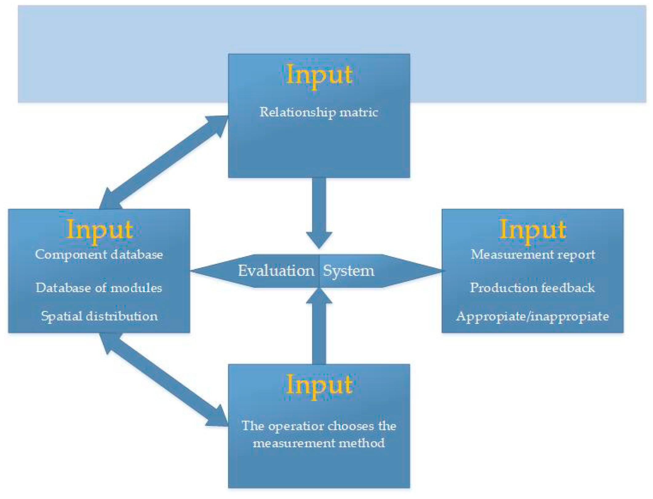
The philosophy of IMCS consists of obtaining information from several types of input data that enter the system in various phases of activity, their subsequent processing by the evaluation system, and outputs from the system with a direct link to the production process. Inputs such as database data and spatial distribution of control modules are obtained from the implementation phase, where individual coordinates are defined. The input as a relational matrix of modules and parameters is determined based on expert recommendations or individual measurements. The last input is a choice that is set by the operator only during the measurement itself. The IMCS system consists of several elements shown in
Figure 2. The part of the inputs where, in addition to the individual databases, the operator's request with additional control/measurement conditions entered is clear. After all inputs have been evaluated, the modules suitable for control are selected and activated. The output can be an inspection report, feedback for production, or sorting of parts into satisfactory and unsatisfactory for further assembly.
3.2. General Model of Control Modules
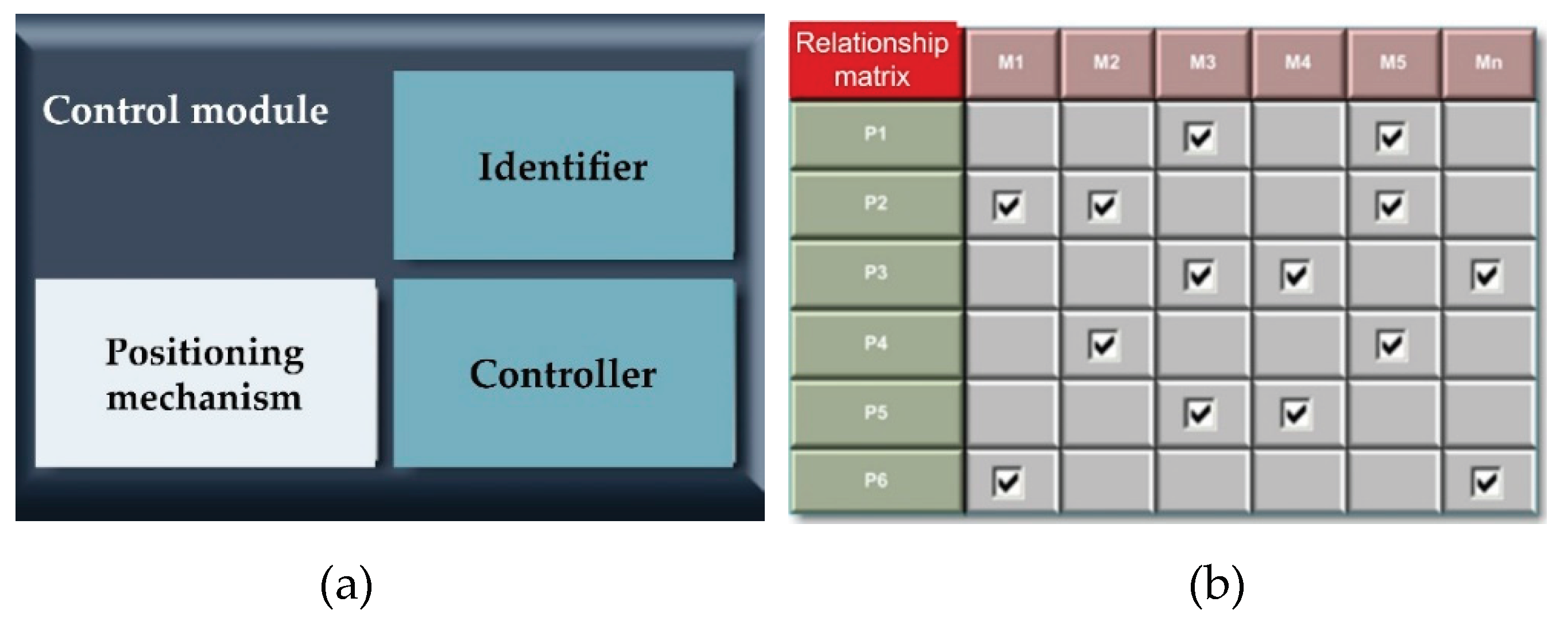
When designing modules for control operations, it is based on a set of ideal components, which are subsequently modified to real components available on the market. These can subsequently be suitably modified based on customer demand. An integral part of the control modules is the identifier and the control unit. In the case of modules that use 2D and 3D technologies, it is necessary to provide a precise positioning mechanism for the positioning of the controlled parts (
Figure 3a), (translational or rotational movement). Finally, control modules also include peripheral devices (position sensors, rotary encoders). In addition to the control modules, the system also consists of one input identification of several so-called integrating modules. The input identification module detects which specific type of component from the defined spectrum entered the control process and sends this information for processing to the decision algorithm. Manipulation members perform the function of connecting individual modules, such as industrial robots, manipulators intended for switching parts between modules, rotating parts, or storage parts after completion of the control process. Each of the control modules M performs the function of an independently operating device and at the same time, it is assigned one or a set of parameters P that can identify
Figure 3b.
3.3. Design of Control Modules
The modular structure provides a wide range of options according to the user's requirements. The mentioned modules always consist of several components. As a rule, it is an identification, positioning, and control member. In addition, there are cabling, sensors (they give information for the start of the measurement or information about the presence of a part in the field of view), connecting material, lighting, etc. Modules include:
Input identification module – the function is to provide information to the control system about which part is at the input. [
19,
20,
21]
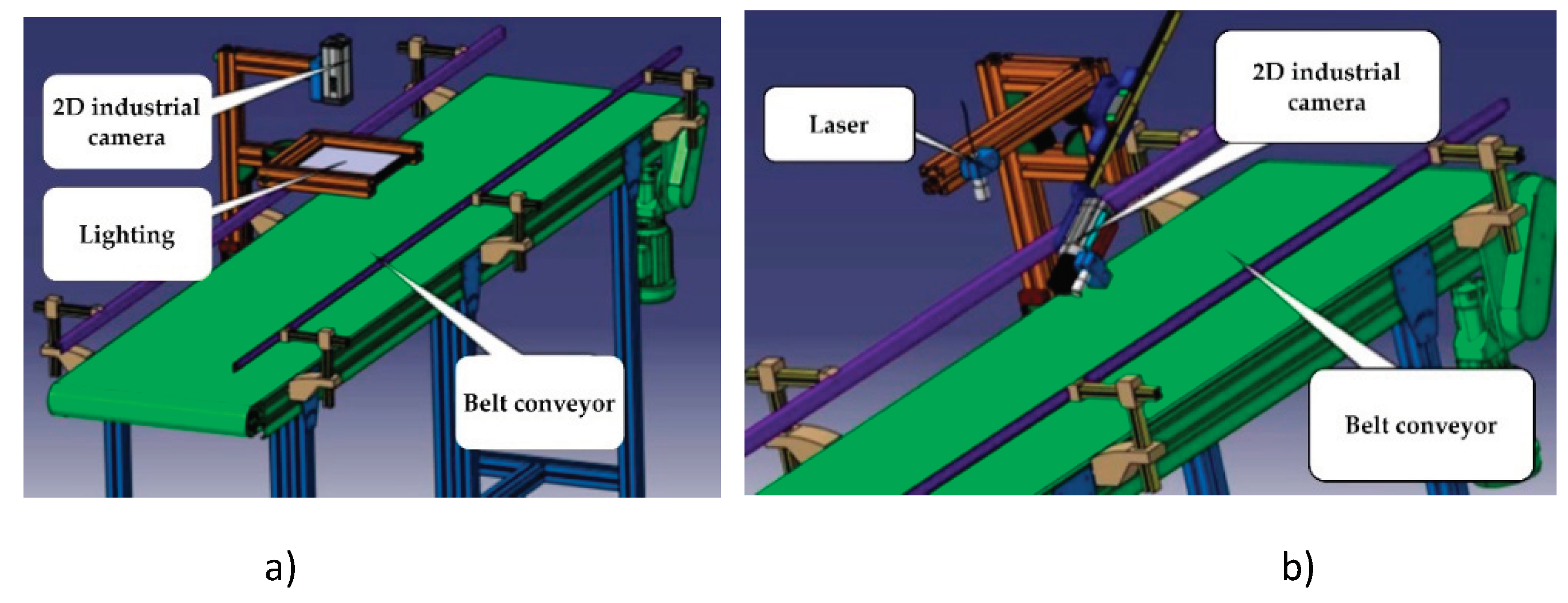
Module with translational movement and 2D measurement – intended for checking elements in 2D view (
Figure 4a).
Module with translational movement and 3D measurement – intended for checking the third dimension of parts (
Figure 4b).
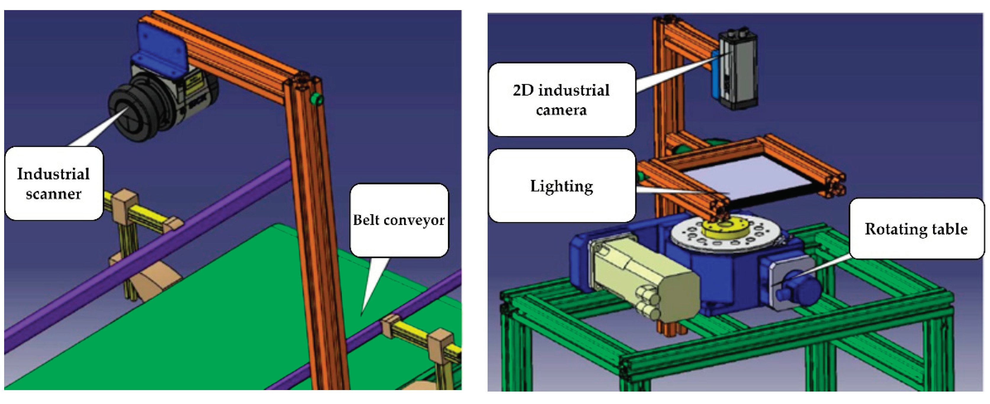
Module with translational movement and profilometer – represents a combination of precise identification device intended for measuring profiles and translational positioning device - belt conveyor (
Figure 5a).
Color control module – contains a special sensor capable of identifying different types of colors of the color spectrum.
Module with translational movement and 2D comparison – with the help of this module you can check e.g. even the simple presence of structural elements on the part.
Module with rotary motion and 2D measurement – uses the same identification device as the module with translational motion, i.e. 2D industrial camera with a higher level of evaluation (
Figure 5b).
A module with rotary movement and 3D measurement – the positioning part would thus be provided with a freely positionable rotary table, which can be used to ensure smooth rotation of the part under the field of view of the 3D camera.
Module with rotary movement and profilometer – the conceptual design of the used components could be based on the previous modules. The advantage of using a profilometer module over a module with a 3D camera is again in the measurement geometry in certain special cases.
Module with rotary movement and 2D comparison – use would be oriented for the identification of simpler structural elements.
Module with digital scale – this module is designed to determine the weight of the inspected part.
Module for measuring the depth of narrow holes – An accurate laser triangulation sensor, which has an appropriate measurement geometry and can measure this depth parameter, is utilized in the module for measuring the depth of small holes.
Integrating handling modules – the task of these modules is to ensure the handling of parts between individual control modules.
An important feature of NC machine tools is the achievable repeatable machining accuracy. In practice, accuracy is determined by the characteristics of the NC machine and the chosen technology.
3.4. IMCS Database System Proposal
It is essential to adjust each component of the system because one of the fundamental concepts is its openness and flexibility. The database structure holds information on tolerance bands, component types, designations, and dimensions in each axis of the coordinate system. The modularity of the entire system—separate data blocks that can be merged in different ways—is evident in the way the database is designed. Three types of databases are used by this intelligent system:
Component database, which keeps comprehensive records of every element and its specifications.
A module database that houses details on every identification and handling module that is accessible.
The measured data database will contain the measured data. It includes measurement data, which the system verifies against the necessary values.
3.5. Design of Management of IMCS and Its Elements
The Potential of Distributed Control in Modular Systems – Modular systems leverage decentralized or distributed management principles, wherein the entire system is partitioned into distinct sub-modules, each equipped with its control systems. Intercommunication among these modules is established, with each module dutifully executing its predefined role.
Utilization of Personal Computers (PCs) in Control Systems – The utilization of personal computers (PCs) within industrial contexts entails unique considerations distinct from other forms of control systems. Within the framework of a decentralized module management system, PCs typically occupy a distinct tier within the overarching hierarchy, assuming the role of a supervisory entity or a dedicated platform for data acquisition, storage, and analysis.
Integration of Microcomputers in Industrial Control – Microcomputers are prevalent in industrial settings, yet they are not primarily employed as control systems tasked with overseeing entire pilot stations.
Adaptation of Robot Control Units in Control Systems – Robot control units are designed exclusively for the management of robotic entities. While they can serve as the control systems for entire pilot stations featuring robots, their integration necessitates collaboration with other control systems such as programmable logic controllers (PLCs).
3.6. Conceptual Design of the Spatial Solution of the Modules
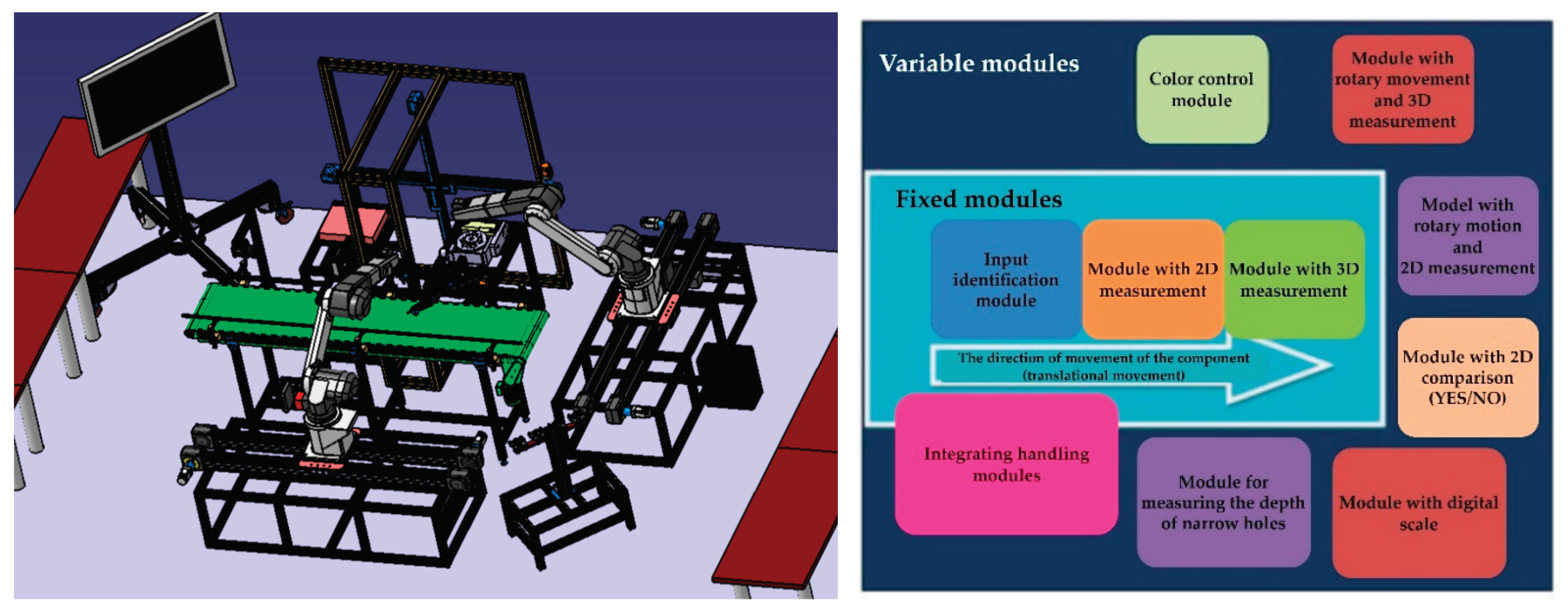
In the spatial solution of the intelligent modular control system IMCS (
Figure 6a), it is necessary to proceed from the possibility of arranging individual modules freely. According to the purpose of use, we propose to divide the modules into (
Figure 6b):
Fixed Modules – Constituting an integral element of the Integrated Modular Control System (IMCS), fixed modules serve as mandatory components within the control process, necessitating identification through a minimum of one module per part. Fundamental data regarding the component type is promptly relayed to the control system for analysis via the information system. Concerning the technical integrity of fixed modules, a recommended solution comprises a fusion of belt conveyors alongside industrial-grade 2D and 3D cameras. Parameters encompassing movement dynamics, resolution accuracy, and other pertinent factors must be meticulously selected by the controlled spectrum of components.
Variable Modules – These modules are dynamically incorporated into the fixed modules upon prompt from the control system. Their primary function is to discern additional parameters that may not have been captured by the fixed modules. Integration is facilitated through modular components, the configuration of which can be adjusted as needed, exemplified by industrial robots or manipulators.
This arrangement was chosen because the cellular structures ensure interconnection between the machines, and save time and space. The activity of the means of production is synchronized, and the material flow is fast. Such an arrangement makes it possible to adapt the behavior of IMCS to the control requirements and its quick configuration is possible.
4. Results
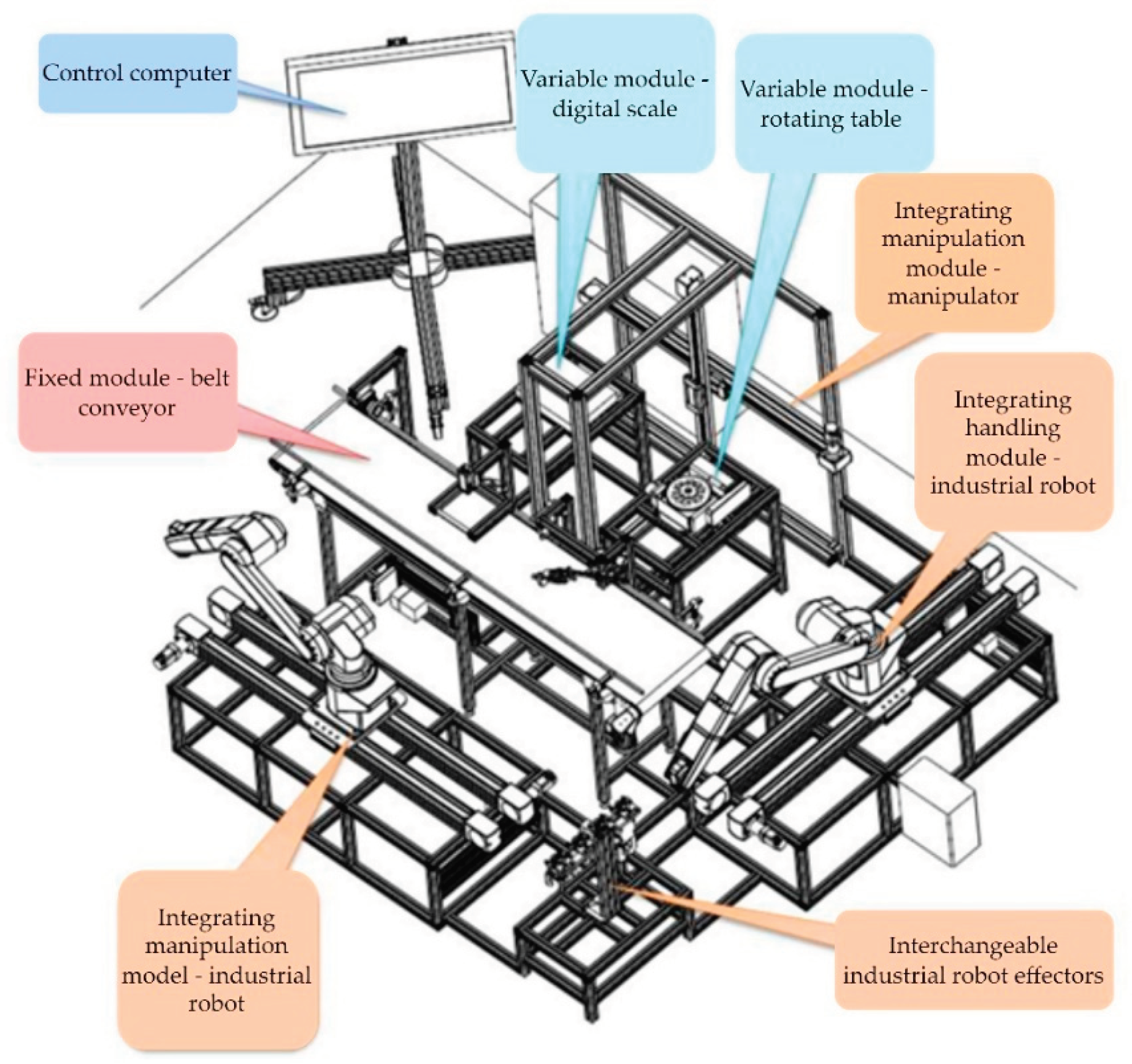
Creating a working prototype of an intelligent modular system for manufactured part quality control using actual parts and real sizes was the primary objective of the practical verification. The system's individual software and hardware components (modules) were described in the preceding chapter. As per the second chapter, the modules were classified into several groups (
Figure 7).
System modularity, flexibility, reconfigurability, and adaptability have been given top priority in the design of the control system for the InMoSysQC component quality control facility. Its purpose is to measure the measured sample's parameters to regulate its quality. The design of an appropriate, flexible control system that can measure and manipulate such samples is strongly tied to this broad range of measured samples.
4.1. PLC Controllers and Their Module Cards
The modular PLC (Programmable Logic Controller) machines of the Mitsubishi Qx type serve as the fundamental integrating units of the overall system. A card with a basic control unit (CPU) and other necessary types of expansion module cards is installed in every modular PLC machine. Among these expansion cards are:
The basic control unit CPU – is designed to perform all basic control calculations and control functions. It is used to perform control algorithms, parameterization, and configuration of the entire device. It is an essential element for maintaining the autonomy of the PLC automaton.
Communication Card CP for IE – The purpose of the Communication Card CP for IE is to use the TCP/IP communication protocol to link the PLC automaton to the IE network. This card allows the PLC automaton in the InMoSys QC device to communicate with other control modules. It is found on each automaton. An open channel for signal transmission between individual modules and their submodules is represented by the Internet Explorer network. An IP (Internet Protocol) address, the network designation (net_no), and the module designation (st_no), or station, are used to identify each module connected to the industrial Ethernet. [
22]
Card with DI digital inputs – The purpose of a card with DI digital inputs is to connect optical, induction, and other sensors, buttons, and control components that output binary information to communication networks but lack an embedded communication processor. Card featuring digital outputs DO Its purpose is to connect actuators (pneumatic, electric, etc.) and display signals as well as other devices that respond to binary input signals but lack an integrated communication processor that would allow them to be connected to communication networks.
Card for the MES operational production system – Card for the operational production system MES - serves for direct connection using the TCP/IP protocol via the IE network to higher levels of distributed control systems. With the help of SQL queries, this PLC card enables the automaton to save and select the required data from information database systems.
Positioning card PM – is intended for control, positioning, and interpolation of servomotors. One card can control multiple axes depending on the type of card.
Communication card for CC-Link – The purpose of the CC-Link communication card is to connect to peripheral devices using the CC-Link communication bus. Multiple devices that can communicate via a serial communication bus, such as CC-Link, can be linked to it.
Communication card for RS-232 – The purpose of an RS-232 communication card is to connect to peripheral devices using the RS-232 communication bus. A serial communication bus called RS-232 only permits two-point connections. There are two communication ports on the card.
Communication between PLCs using Ethernet – Ethernet is used for communication between PLCs in IMCS. Every PLC has an Ethernet module that may be used for emailing, FTP server functions, PLC-to-PLC, PLC-to-PC, and PLC-to-camera, among other things. Open connections and connections meant for the system are the two main categories into which connections can be separated [
23,
24,
25,
26].
Communication between PC and PLC – Communication between PC and PLC - as mentioned, every IMCS PLC contains an Ethernet module, which is also used for communication between PC and PLC. For this method of exchanging information, we used two types - communication using GX Works and communication using the MC protocol.
Communication via GX Work – with the help of communication via ethernet with GX Works, we can monitor the program while it is running and monitor its behavior or simulate certain states. Setting up access to the ethernet in GX Works is in Connection Destination, where we can edit connections or create new ones. After selecting the connection, we set "PC side I/F" to "Ethernet Board" and specify the PC network number and PC station number, then we set the Ethernet module.
Communication using the MC protocol – when communicating using the MC protocol, the connection can be opened or used for the system. We use an open connection for IMCS.
4.2. Characteristics of the Selected Control Object
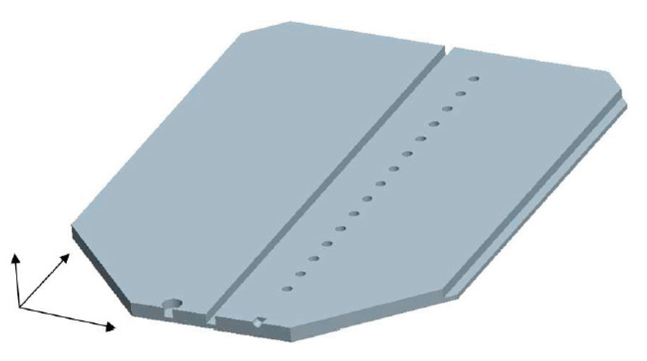
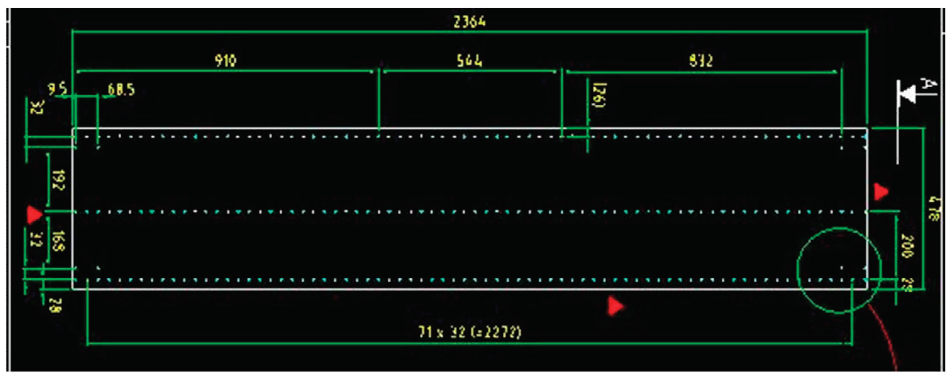
The company operates in the furniture industry, producing chipboard parts. The aim of this case study was, first, to speed up the adjustment control of cutting and drilling tool heads directly in the production hall. The external dimensions of the produced parts, the exact position and depth of the structural elements on the parts, the perpendicularity of the edges, and the dimensions of the profile groove had to be checked, it was a matter of course that the complete archiving of the achieved data was ensured. All these conditions had to be met by the facility, as well as the financial return of the entire investment, in a certain time. Different types of holes (continuous, non-continuous), grooves, half-grooves, and recesses are produced on the parts. The holes are located on several sides of the parts and have a different ratio of depth to diameter. The measurement procedure is predicated on information from specified wooden part templates that are kept in the database. A universal template for a wooden element is shown in
Figure 8. Templates for actual wooden pieces are made using this universal template. Every wooden part template has components like a hole and a corner point. A groove entity can also be formed by a collection of points.
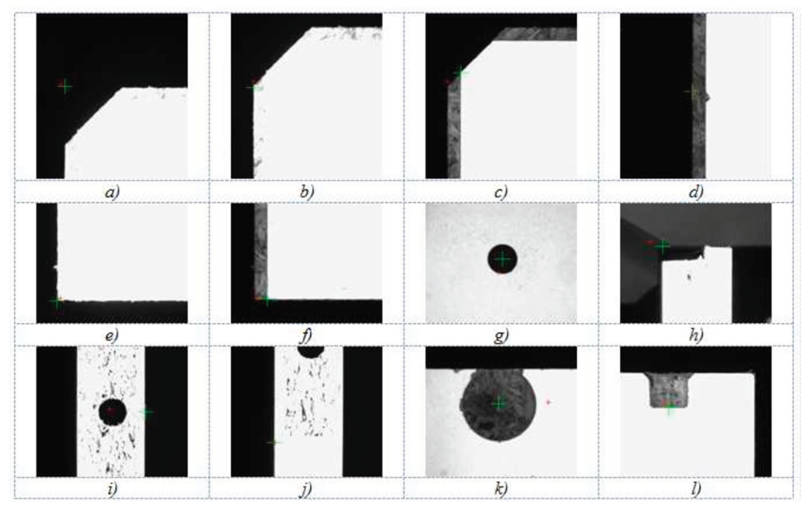
Through the OPC server, the industrial PC communicates with the camera regarding the type of measured item and its color. Using a positioning device and information from the database, the industrial PC places the camera beneath the anticipated object. The corresponding subprogram is launched by the type of the measured entity once the camera has been positioned at a predetermined location beneath it. After that, an image of the entity is captured with exposure matching the color of the measured portion. The image is then segmented using thresholding, detection, entity identification, and the measurement procedure itself. Deviations of the object from its predicted position and dimensions are sent to the PC following the subprogram's execution. The camera system measurement procedure is broken down into multiple subprograms dependent on the type of measured entity. These subprograms are started using data from the industrial PC's control system.
Figure 9 contains the fundamental scanned entities. Examples of chosen measurement objects are portions from actual photographs that have the estimated position indicated as a large target for visual examination and the field of view center indicated as a tiny target.
The most complicated case is the calculation of the position and diameter of the incomplete hole on the edge of the part (
Figure 9k). In this case, the position and diameter of the hole are obtained using a search engine that works on the principle of object similarity search. When programming the camera, it was necessary to teach the search engine all the necessary objects, defining their position and dimensions. The best solution turned out to be the creation of perfect reference objects for which the exact position and dimensions were calculated.
4.3. The Sequence of Implementation and Presentation of Results
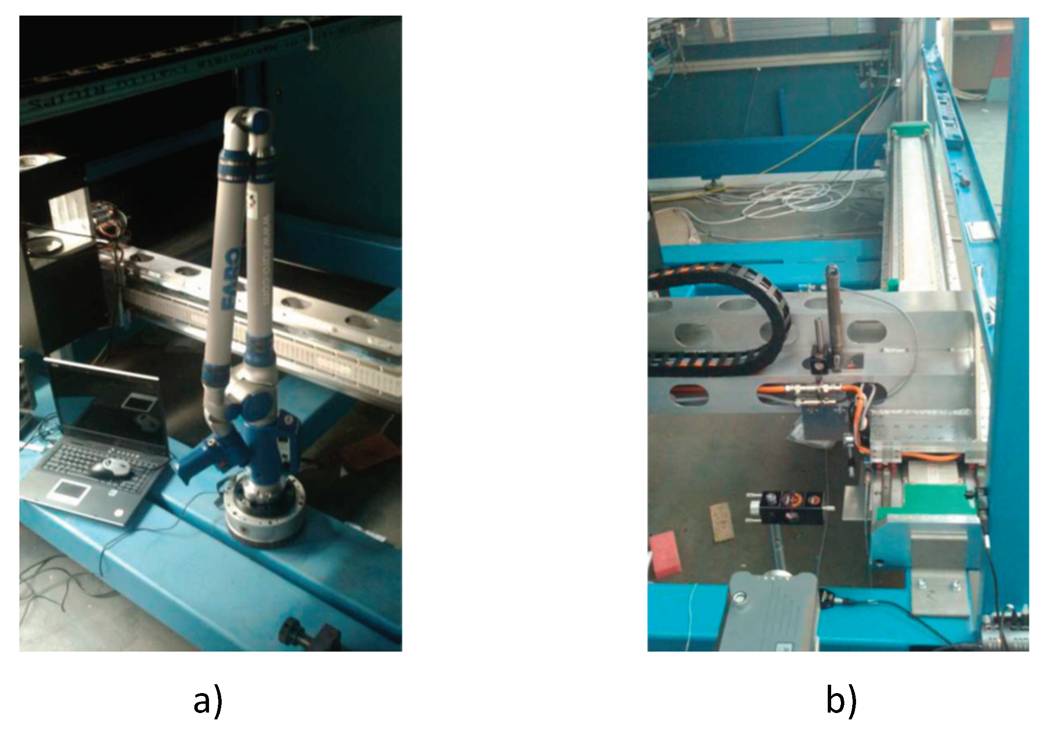
The device was assembled and tested in experimental conditions. The construction team of workers started with the assembly work, and the programmers worked simultaneously with them on the development of the software part. We verified the accuracy of the assembly using the FARO 3D measuring arm (
Figure 10a). During the test operation, we adjusted the correction parameters based on the results of the measurement using a laser interferometer, when we measured the accuracy as the repeatable positioning accuracy of all positioning mechanisms (
Figure 10b).
After the approval of the number of control measurements, the device had to be disassembled, and after the device was transported, assembly was carried out again in the premises of the production hall.
4.4. Application of the Methodology in Real Conditions
The application of the methodology in practical conditions was divided into three phases: the preparatory phase, implementation phase, and output phase.
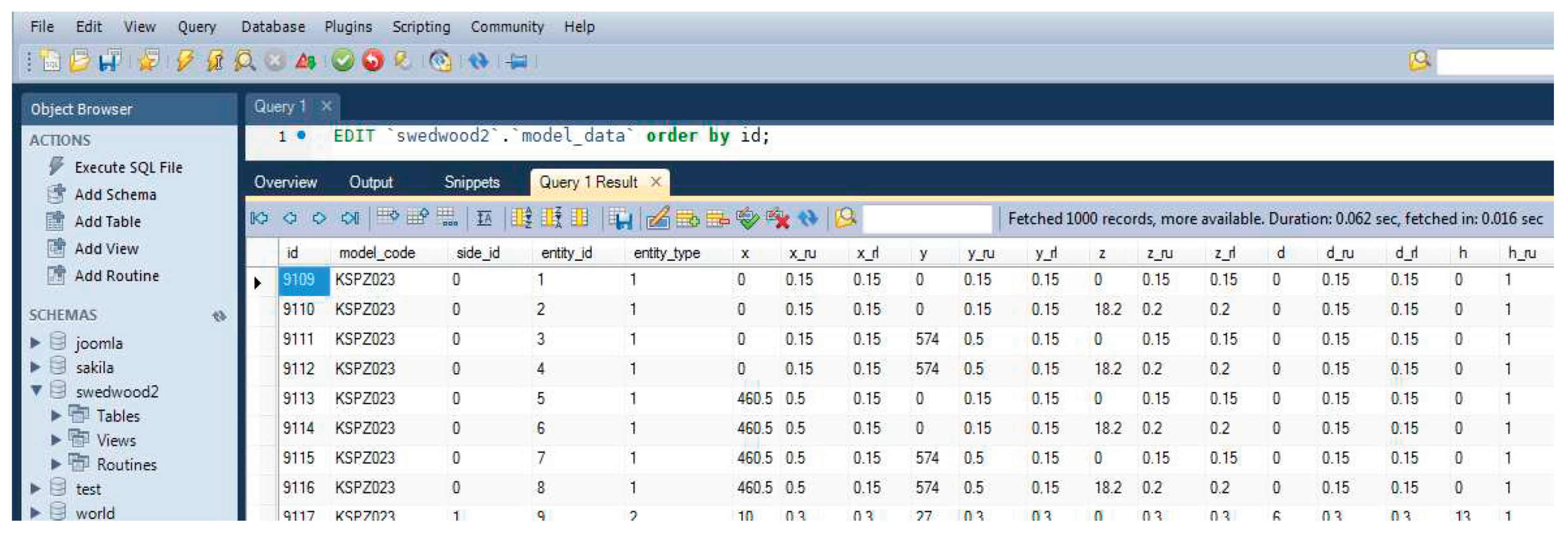
Preparatory phase - based on the shape, the parts were classified into the group of surface parts. The next step was integrating the model data into the component database. The information it stores includes part dimensions, the location, and depth of individual holes and grooves, details about the side that a given parameter is located on, the "zero point" to which all data is compared, the part name, the tolerance field for the specified parameter, and an identification number for each parameter (
Figure 11).
To unify measurements, the term "zero point" had to be developed because, up until this point, manufacturers measured items without using any standards.
Figure 12 displays the device database's structure.
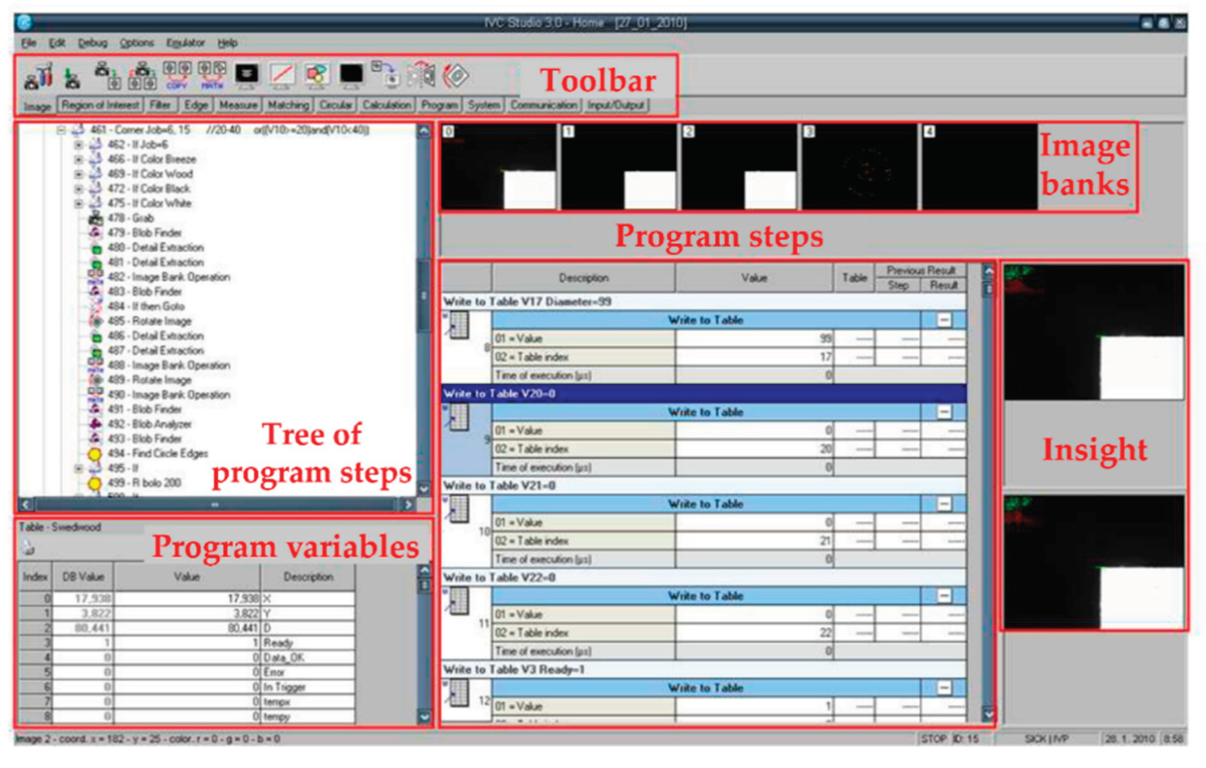
During the setup parameterization, all evaluation sequences of the program for a specific evaluation module were determined. Setting the correct exposure and recognition algorithms is shown in
Figure 13.
Implementation phase – Every aspect of the component, including its length, width, thickness (X, Y, and Z), the diameter of the hole, coordinates of the chosen element's position (x, y, and z), and depth of the hole, was chosen for examination. Because the parts may be made in multiple color variations, the operator chooses the color of the component to be measured and decides on the measurement technique in further detail. This is the data needed for a given measurement independently. The operator also needs to choose additional required options (
Figure 14).
The program chose a precise 2D measuring system for determining the size and locations of the holes from the relational matrix based on the parameters that were to be measured. The depth of the holes and grooves that were created was to be measured using a triangulation laser sensor, which is the only one whose measuring design guarantees complete identification of the specified parameter. Another algorithm for figuring out when to activate the modules found that you must figure out where the holes are made and then use a laser sensor to figure out how deep the hole is.
Outputs phase – after the measurement is finished, the measured data is exported to the database and compared with the model data. The operator can display the measured deviations on the monitor or print them out. The measured data is copied once a day to the main server of the production company, where the user can monitor individual deviations during a certain time interval, check the parameters independently, and, based on this, determine corrective solutions such as replacement of a drilling head that exhibits frequent drilling errors. After the production of the standard, the certified company carried out measurements at different temperatures in the interval from 15 °C to 28 °C. These measurements served as a basis for determining the thermal expansion of the material used because the manufacturer could not provide us with the exact data. We calculate the thermal expansion coefficient ∝ from the relationship:
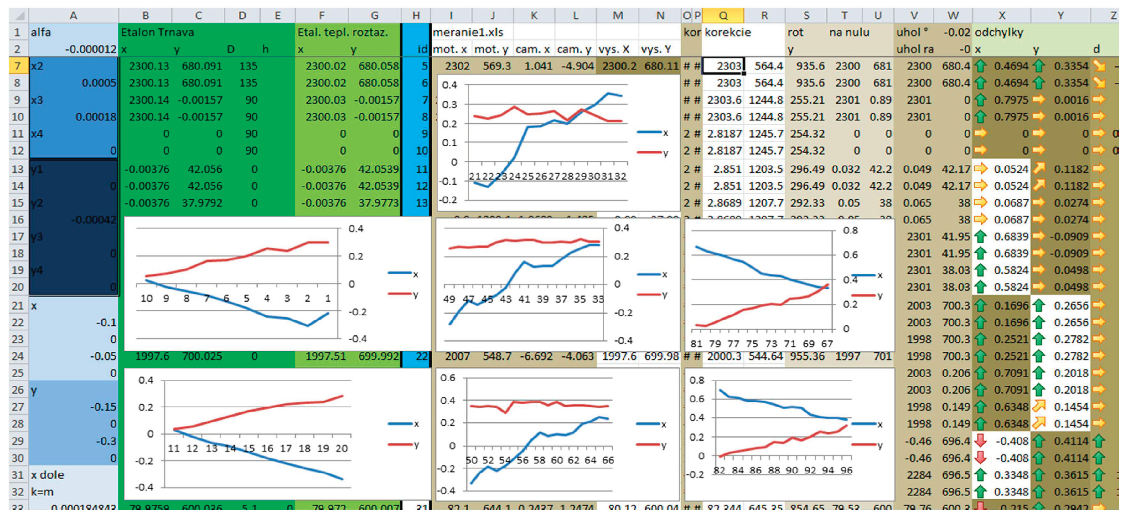
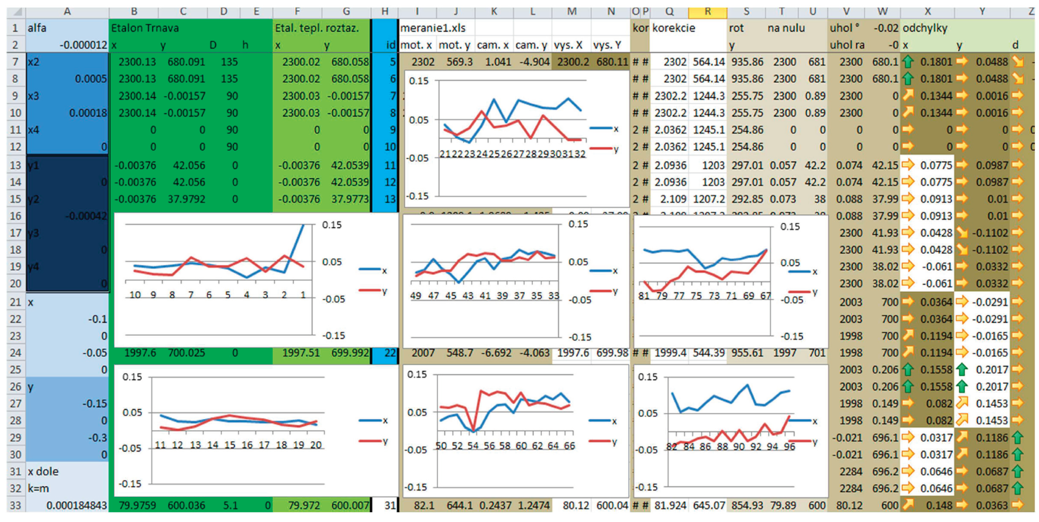
Only table data was provided, which did not fully correspond to reality ∝_ 15.7 ⁄ ∙ ! ∙ 10"#. During the calibration measurements, the database values (measured by a certified company) and the actual values supplemented with the coefficient of thermal expansion (measured by the measuring device) were compared. Based on the outputs from the measurement of the standard, we can automatically correct all measured values at various temperature changes. Samples of value curves in the individual axes, before and after setting the temperature change corrections, can be seen in
Figure 15 and
Figure 16. The figures show the deviations of the values in the individual axes for the corresponding measured holes, the x-axis is the number of the measured holes, and the y-axis shows deviation in millimeters from the actual value.
The figures (
Figure 15 and
Figure 16) show the deviations of values in individual axes for the corresponding measured holes. The x-axis is the number of the measured hole, the y-axis shows the deviation in millimeters from the actual value.
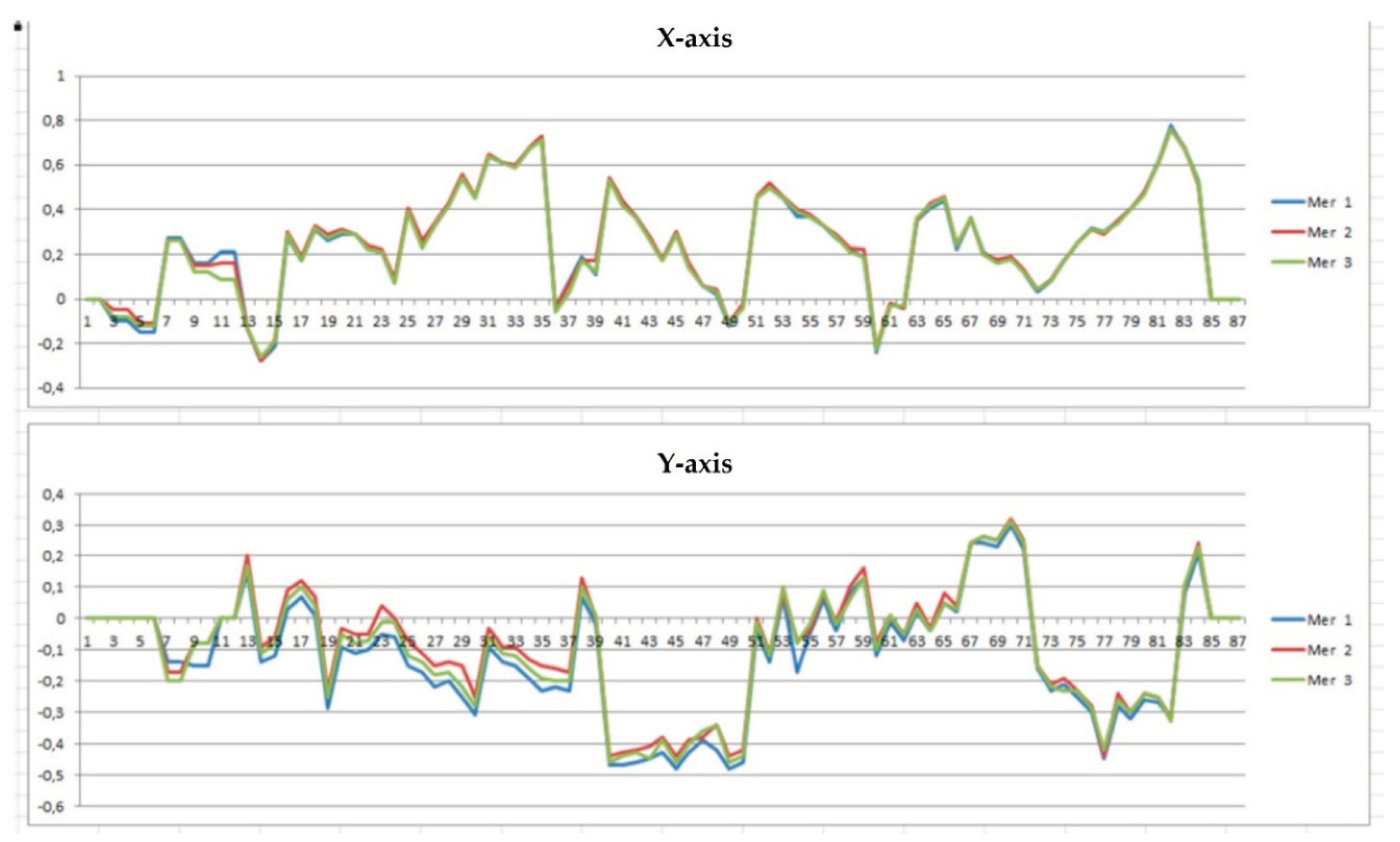
Individual axis achieved deviations are displayed in
Figure 17. The graph displays the repeatability of the automated device's measurement as well as the accuracy of the chipboard part production. Using the gadget resulted in an average of 40–60% time savings over the prior manual control method. Entire measurement data archiving is guaranteed, and finally, human error— which contributed significantly to this process's error rate—was eradicated.
5. Discussion
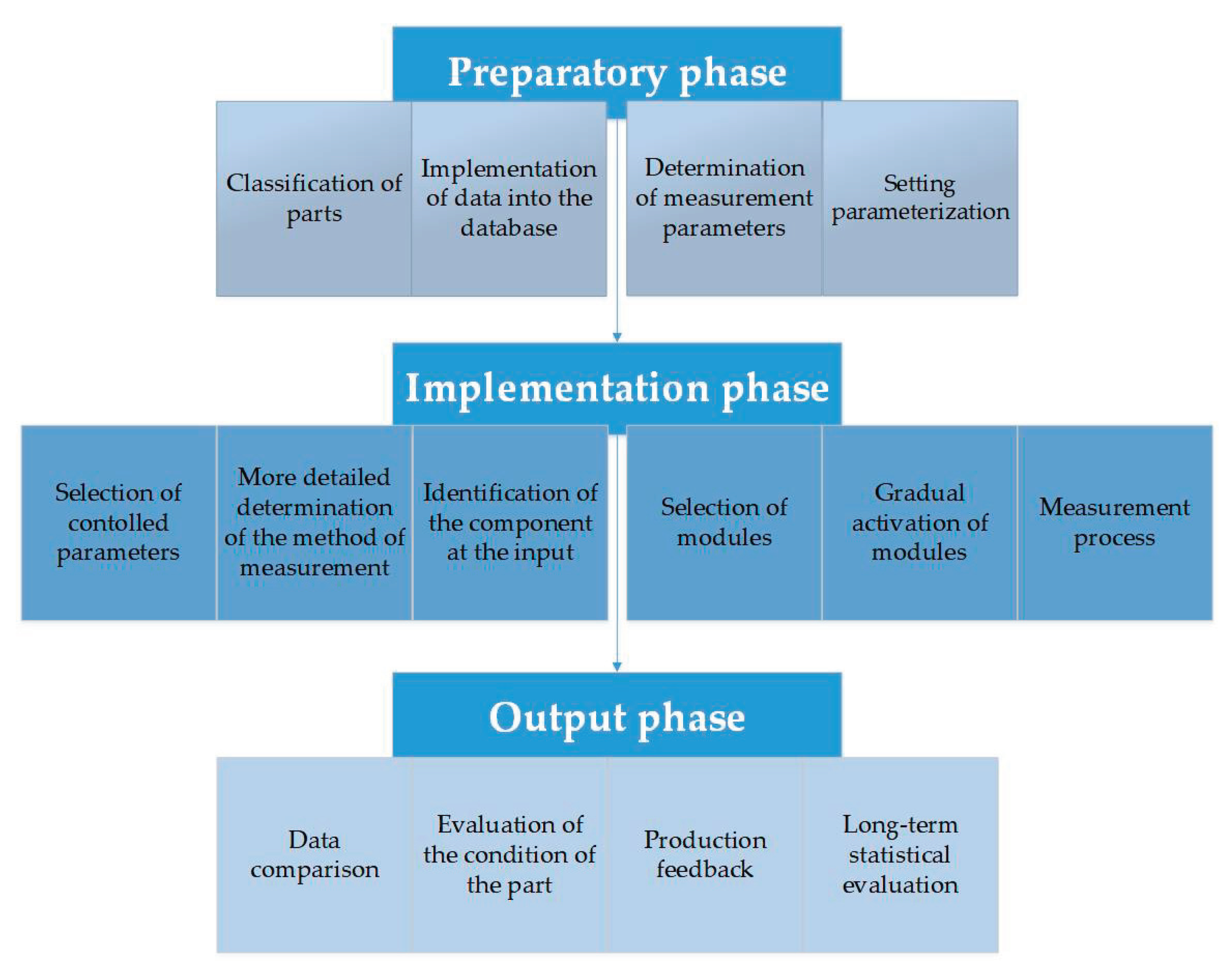
There are three primary stages to the IMCS activity technique (
Figure 18):
A series of tasks that must be completed before the initiation of the control process define the preparatory phase. These mostly involve the categorization and classification of components as well as the entry of data into distinct databases. The initial setting parameterization is a crucial step in the preparation phase.
Implementation phase – the implementation phase is characterized by the control process on the devices themselves. It is part of the process when the operator directly selects individual parameters to be checked in the control menu. In this phase, the selection and activation of modules suitable for checking the required parameters on individual components is also carried out automatically.
Output phase – consisting of a comparison of measured and actual values. Based on the actual measured values, it can perform quick corrective actions toward production or long-term statistical evaluation of the measured data.
Four fundamental classes of checked parts were selected for the practical verification solution: flat parts, cabinet parts or 3D plastic injection moldings and moldings, rotary parts, and shaft parts. A photo of a particular part, a camera image, or its three-dimensional model are examples of auxiliary data that provide a better visual representation of categorized parts.
Based on the shape difference, it is possible (most often experimentally) to define the relationship of the measured parameters depending on the technical devices used.
Initialization of variables is requested at the beginning. [
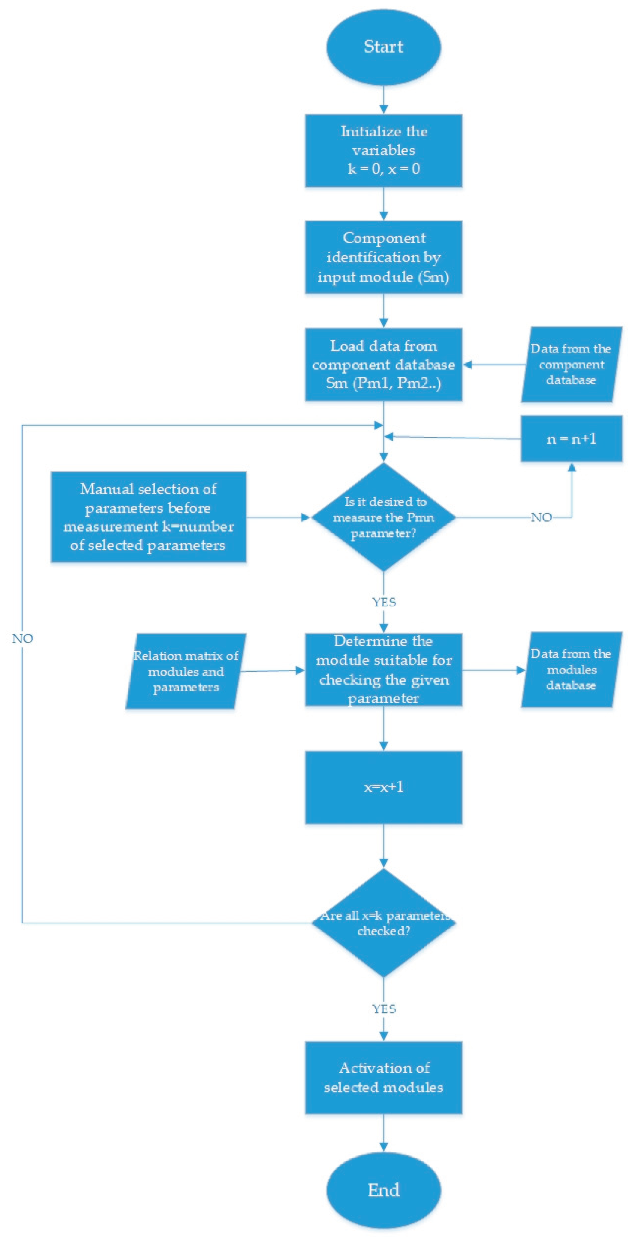
33] In the initial phase, the part (Sm) is identified by the input identification module. In the next block, data for a specific part is loaded from the component database shown in the mathematical equation (4). Subsequently, a check occurs, which determines whether the specific parameter represented in the mathematical equation (5) was selected from the entire set of parameters. The number of selected parameters (the number of elements of the set of selected parameters) is written into the variable "k". If this parameter is not selected, the next parameter is checked automatically. If the algorithm identifies the selected parameter, the module suitable for its control is determined. We will use the relational matrix of parameters and modules as well as the database of modules as input data. This will check one parameter. This process (
Figure 19) is repeated until all parameters selected by the operator (x=k) are checked. Subsequently, individual modules are activated.
6. Conclusions
The article provides an innovative approach to solving the problem of control operations before entering assembly. The methodology proposed in this work consists of connecting several types of functional blocks in each of the phases mentioned in Chapter 5.4. Two decision-making algorithms are used in the work. One is an algorithm for selecting suitable types of control modules and the other is an algorithm for the gradual activation of individual modules. The methodology was applied in the design of the automated measuring device AMZ_01 while using a significant part of its system elements. Based on results from the studied literature, achieved theoretical and practical knowledge, and designed and verified solution, it is recommended for further research in this area to focus individually on all phases of the system. Furthermore, the recommendation in further research is, for example:
Detailed design of the structure of database systems about modularity devices and the complexity of the entire system.
Focus on another method of selecting modules suitable for parameter control, while the use of expert systems appears to be the most advantageous in this area.
Creation of a complex software package for the design and management of control systems [
33,
34,
35].
Equipment in the pre-assembly stage [
36,
37,
38,
41].
Development and application of colonic systems [
39,
40,
41].
The design of control devices during the pre-assembly phase presents a promising avenue for enhancing product quality and mitigating costs associated with detecting deficiencies in the assembly process. The proposed system entails the utilization of distinct functional modules capable of overseeing one or multiple measurement/control parameters. Users are afforded a breadth of options to tailor and oversee this process, including adjustments to workplace layouts and the selection of specific controlled parameters [
42,
43].
The theoretical segment delineates elements of the system pertinent to research, encompassing an analysis of the current landscape in flexible, cost-effective control device domains. It elucidates how production process design paradigms intersect with advancements in information and communication technologies. However, existing systems are largely tethered either to human collaboration or the labor-intensive configuration of control processes and measurements. Practical applications involve approaches and devices leveraging state-of-the-art technologies to fulfill diverse parameter identification requisites.
Nonetheless, prevailing devices predominantly manifest either as single-purpose, high-speed units capable of discerning limited parameters or as highly precise multi-purpose devices unable to scrutinize every manufactured part within feasible time frames. This creates an opportunity for the deployment of intelligent modular control devices, as discussed herein.
The crux of the discourse delineates components of the Integrated Modular Control System (IMCS), including classification and database systems, as well as control algorithms. This section expounds upon the methodology of flexible IMCS, and potential variants of control modules predicated on cost-effective automation. Integral to IMCS is the establishment of a comprehensive relational matrix connecting controlled parameters with control modules. Decision algorithms governing the selection and sequential activation of control modules ensure system functionality. The proposed solution obviates the necessity for specialized experts to continuously design new control systems in response to production changes. Rather, experts are engaged solely during the initial system implementation phase, with subsequent operations being overseen by operators.
Author Contributions
“Conceptualization, V.B. and B.M.; methodology, P.M.; software, P.M; validation, B.M.; formal analysis, V.B.; and J.Z. investigation, B.M.; resources, V.B.; data curation, L.D.; writing—original draft preparation, V.B.; writing—review and editing, V.B.; visualization, L.D.; supervision, M.G.; project administration, J.Z.; funding acquisition, B.M. All authors have read and agreed to the published version of the manuscript.”
Institutional Review Board Statement
Not applicable.
Informed Consent Statement
Not applicable.
Data Availability Statement
Data sharing not applicable.
Acknowledgments
This work was supported by the Slovak Research and Development Agency under contract No. APVV 19-0305.
Conflicts of Interest
The authors declare no conflict of interest.
References
- Lorincova, S., Cambal, M., Miklosik, A., Balazova, Z., Babellová, Z. G., & Hitka, M. Sustainability in business process management as an important strategic challenge in human resource management. Sustainability (Switzerland) 2020, 12(15). Scopus. [CrossRef]
- Plura, J., Vykydal, D., Tošenovský, F., & Klaput, P. Graphical Tools for Increasing the Effectiveness of Gage Repeatability and Reproducibility Analysis. Processes 2023, 11(1). Scopus. [CrossRef]
- Pekarcikova, M., Trebuna, P., Kliment, M., Trojan, J., Kopec, J., Dic, M., & Kronová, J. Case Study: Testing the Overall Efficiency of Equipment in the Production Process in TX Plant Simulation Software. Management and Production Engineering Review 2023, 14(1), 34–42. Scopus. [CrossRef]
- Rofar, J., Macek, P. InMoSys QC - holonic automated inspection cell. In: Gyártás - automatizálás 2013 = Factory automation 2013 : University of Pannonia, Veszprém, Hungary: May 21-22, 2013. Veszprém: University of Pannonia, 2013. ISBN 978-615-5044-80-9. pp. 100-105.
- Rudnev, A., Sevidova, E., Titarenko, O., Kotliar, A., Baranov, V., Yurchenko, O., & Edl, M. Effect of Various Solid Lubricants on Diamond Grinding of Heat-Resistant Stainless Steel. Lecture Notes in Networks and Systems 2023, 762 LNNS, 117–126. Scopus. [CrossRef]
- Krajcovic, M.; Furmannova, B.; Grznar, P.; Furmann, R.; Plinta, D.; Svitek, R.; Antoniuk, I. System of parametric modelling and assessing the production staff utilisation as a basis for aggregate production planning. In Applied sciences, Basel : Multidisciplinary Digital Publishing Institute. 2021; Volume 11, Issue 19, ISSN (online) 2076-3417. [CrossRef]
- Antoniuk, I., Svitek, R. Krajcovic, M., Furmannova, B. Methodology of design and optimization of internal logistics in the concept of Industry 4.0. Transportation Research Procedia. 2021, 55, 503–509. [Google Scholar] [CrossRef]
- Micieta, B.; Durica, L.; Binasova, V. Bio-Inspired Manufacturing Multi-Agent System for Control and Coordination of AGV Systems. 2016. [Google Scholar] [CrossRef]
- Furmannova, B. – Gabajova, G. – Matys, M. 2021. Training centers in industry. In: Technolog. ISSN 1337- 8996, 2021, 13 (4), pp. 15-19.
- Liu, C., Cai, W., Zhang, C., & Wei, F. Data-driven intelligent control system in remanufacturing assembly for production and resource efficiency. International Journal of Advanced Manufacturing Technology 2023, 128(7–8), 3531–3544. Scopus. [CrossRef]
- Gorkavyy, M., Ivanov, Y., Sukhorukov, S., Zhiganov, S., Melnichenko, M., Gorkavyy, A., & Grabar, D. Improving Collaborative Robotic Complex Efficiency: An Approach to the Intellectualization of the Control System †. Engineering Proceedings 2023, 33(1). Scopus. [CrossRef]
- Wang, H., Lin, C., & Li, J. Design of Intelligent Control System for Installation Machine of Shield Tunnel Middle Partition Wall. Tunnel Construction 2023, 43(4), 698–710. Scopus. [CrossRef]
- Eswaran, M., Inkulu, A. K., Tamilarasan, K., Bahubalendruni, M. V. A. R., Jaideep, R., Faris, M. S., & Jacob, N. Optimal layout planning for human robot collaborative assembly systems and visualization through immersive technologies. Expert Systems with Applications 2024, 241. Scopus. [CrossRef]
- Zhang, Z., Ji, Y., Tang, D., Chen, J., & Liu, C. Enabling collaborative assembly between humans and robots using a digital twin system. Robotics and Computer-Integrated Manufacturing 2024, 86. Scopus. [CrossRef]
- Yuan, G., Liu, X., Zhu, C., Wang, C., Zhu, M., & Sun, Y. Multi-objective coupling optimization of electrical cable intelligent production line driven by digital twin. Robotics and Computer-Integrated Manufacturing 2024, 86. Scopus. [CrossRef]
- Furmannova, B., Gabajova, G., Matys, M. Process improvement using DMAIC. In: Technológ. ISSN 1337-8996. 2022, 14 (4), p. 22-25.
- Liu, H.; Zhou, L.; Zhao, J.; Wang, F.; Yang, J.; Liang, K.; Li, Z. Deep-Learning-Based Accurate Identification of Warehouse Goods for Robot Picking Operations. Sustainability (Switzerland) 2022, 14. [Google Scholar] [CrossRef]
- Liu, L.; Zou, Z.; Greene, R.L. The Effects of Type and Form of Collaborative Robots in Manufacturing on Trustworthiness, Risk Perceived, and Acceptance. International Journal of Human–Computer Interaction 2023, 1–14. [Google Scholar] [CrossRef]
- Mason, A.; Korostynska, O.; Cordova-Lopez, L.E.; Esper, I.; Romanov, D.; Ross, S.; Takács, K.; Haidegger, T. Meat Factory Cell: Assisting Meat Processors Address Sustainability in Meat Production. In Proceedings of the 2021 IEEE 21st international symposium on computational intelligence and informatics (CINTI); IEEE, 2021; pp. 103–108.
- Mai, V.; Vanderborght, B.; Haidegger, T.; Khamis, A.; Bhargava, N.; Boesl, D.B.O.; Gabriels, K.; Jacobs, A.; Moon, Aj.; Murphy, R. The Role of Robotics in Achieving the United Nations Sustainable Development Goals—The Experts’ Meeting at the 2021 IEEE/RSJ IROS Workshop [Industry Activities]. IEEE Robotics & Automation Magazine 2022, 29, 92–107. [Google Scholar] [CrossRef]
- Boesl, D.B.O.; Haidegger, T.; Khamis, A.; Mai, V.; Mörch, C. Automating the Achievement of SDGs: Robotics Enabling & Inhibiting the Accomplishment of the SDGs. 2021.
- DiLuoffo, V.; Michalson, W.R.; Sunar, B. Robot Operating System 2: The Need for a Holistic Security Approach to Robotic Architectures. International Journal of Advanced Robotic Systems 2018, 15, 1729881418770011. [Google Scholar] [CrossRef]
- Vinod, B.; Bindu, B.; Koushik Karan, G.N.; Jayanth Akash, V.E.; Dinesh Kumar, S. Design and Implementation of the 6-DoF Robotic Manipulator Using Robot Operating System. International Journal of Nonlinear Analysis and Applications 2021, 12, 1753–1760. [Google Scholar] [CrossRef]
- Giret, A. A Multi Agent Methodology for Holonic Manufacturing Systems. In Proceedings of the Proceedings of the fourth international joint conference on autonomous agents and multiagent systems; 2005; p. 1375.
- Botti, V.; Giret, A. Holonic Manufacturing Systems; Springer, 2008; ISBN 1848003099.
- Koestler, A. Arthur Koestler. Zeppelins 1905, 60. [Google Scholar]
- Russell, S.J. Artificial Intelligence a Modern Approach; Pearson Education, Inc., 2010; ISBN 0136042597.
- Macek. P. Modular intelligent checking system. Dissertation thesis. University of Zilina, Faculty of Mechanical Engineering, Department of Industrial Engineering. 2012.
- Micieta, B., Macek, P. Development of intelligent modular quality checking system – InMoSysQC. In: Digital factory management methods and techniques in engineering production : Vol. V. Bielsko-Biała: Wydawnictwo Akademii techniczno-humanistycznej 2011, ISBN 978-83-62292-57-8. pp. 73-78.
- Vrba, P.; Tichy, P.; Marik, V.; Hall, K.H.; Staron, R.J.; Maturana, F.P.; Kadera, P. Rockwell Automation’s Holonic and Multiagent Control Systems Compendium. IEEE Transactions on Systems, Man, and Cybernetics, Part C (Applications and Reviews) 2011, 41, 14–30. [Google Scholar] [CrossRef]
- Harcuba, O.; Vrba, P. Ontologies for Flexible Production Systems. In Proceedings of the 2015 IEEE 20th conference on emerging technologies & factory automation (ETFA); IEEE, 2015; pp. 1–8.
- Malavolta, I.; Lewis, G.A.; Schmerl, B.; Lago, P.; Garlan, D. The Journal of Systems & Software. 2021.
- Pałka, P.; Zieliński, C.; Dudek, W.; Seredyński, D.; Szynkiewicz, W. Communication-Focused Top-Down Design of Robotic Systems Based on Binary Decomposition. Energies 2022, 15, 7983. [Google Scholar] [CrossRef]
- Quigley, M.; Conley, K.; Gerkey, B.; Faust, J.; Foote, T.; Leibs, J.; Wheeler, R.; Ng, A.Y. ROS: An Open-Source Robot Operating System. In Proceedings of the ICRA workshop on open source software; Kobe, Japan, 2009; Vol. 3, p. 5.
- Zhou, D.; Xu, K.; Lv, Z.; Yang, J.; Li, M.; He, F.; Xu, G. Intelligent Manufacturing Technology in the Steel Industry of China: A Review. Sensors 2022, 22, 8194. [Google Scholar] [CrossRef] [PubMed]
- Ostrosi, E.; Fougères, A.-J.; Zhang, Z.-F.; Stjepandić, J. Intelligent Modular Design with Holonic Fuzzy Agents. Advances in Manufacturing 2021, 9, 81–103. [Google Scholar] [CrossRef]
- Macherki, D.; Diallo, T.M.L.; Choley, J.-Y.; Guizani, A.; Barkallah, M.; Haddar, M. The Q-Holon: A Quadridimensional Holon to Design and Operate an Adaptive and Scalable Architecture for CPPS. In Proceedings of the 2020 21st international conference on research and education in mechatronics (REM); IEEE, 2020; pp. 1–6.
- Krajcovic, M. , Gabajova, G., Matys, M., Furmannova, B., Dulina, L. Virtual Reality as an Immersive Teaching Aid to Enhance the Connection between Education and Practice. Sustainability 2022, 14(15), 9580. [Google Scholar] [CrossRef]
- Grznar, P.; Gregor, M.; Mozol, S.; Krajcovic, M.; Dulina, Ľ.; Gaso, M.; Major, M. A system to determine the optimal work-in-progress inventory stored in interoperation manufacturing buffers. In Sustainability. Basel: Multidisciplinary Digital Publishing Institute, 2019. 11(14), Article Number 3949, ISSN (online) 2071-1050. [CrossRef]
- Grznar, P.; Krajcovic, M.; Gola, A.; Dulina, L.; Furmannova, B.; Mozol, S.; Plinta, D.; Burganova, N.; Danilczuk, W.; Svitek, R. The use of a genetic algorithm for sorting warehouse optimisation. In Processes. Basel: Multidisciplinary Digital Publishing Institute, 2021. Volume 9, Issue 7, ISSN (online) 2227-9717. 3390. [Google Scholar] [CrossRef]
- Micieta, B., Jancusova, M., Macek, P., Durica, J. Designing measuring equipment and camera systems in manufacturing. DAAAM International Scientific Book, 2014.
- Durica et al. Camera Systems for automated equipment. In: Technolog. ISSN 1337-8996. 2014, 6(4), pp. 5-8.
- Durica J., Macek P. Optical measure systems in AMZ02. In: InvEnt 2014: industrial engineering - navigating the future: proceedings of the international conference, Zilina: University of Zilina, 2014. ISBN 978-80-554-0879-8. pp. 54-57.
|
Disclaimer/Publisher’s Note: The statements, opinions and data contained in all publications are solely those of the individual author(s) and contributor(s) and not of MDPI and/or the editor(s). MDPI and/or the editor(s) disclaim responsibility for any injury to people or property resulting from any ideas, methods, instructions or products referred to in the content. |
© 2024 by the authors. Licensee MDPI, Basel, Switzerland. This article is an open access article distributed under the terms and conditions of the Creative Commons Attribution (CC BY) license (http://creativecommons.org/licenses/by/4.0/).

