1. Introduction
Developing highly efficient artificial photoconversion systems over a photocatalyst with a wide wavelength range of light is very challenging.[
1] Titanate and titanate-based wide bandgap semiconductor photocatalysts have been investigated for decades due to their good abundance, biocompatibility, cost effectiveness, photoelectron separation, and long-term thermal stability.[
2,
3,
4,
5,
6,
7] The photocatalytic performance of titanate is strongly dependent on its morphology and structure, as the good nanoscale titanate photocatalysts usually show the superior functional properties in the form of nanorods,[
8,
9] nanoparticles (NPs),[
10,
11] and hollow spheres[
12]. Specifically, 1-dimensional (1D) titanate nanostructures, such as the photocatalytic nanowires (NWs), attract lots of attention because of their large specific surface area and the ease for the photogenerated charge carriers to transfer along their longitudinal surface.[
13,
14,
15,
16,
17] However, the large bandgap of titanate (3.0 ~ 3.2 eV) limits the usability of the wide wavelengths of solar energy.[
18,
19,
20,
21] This limitation is further exacerbated by the fast recombination of photoelectron-hole pairs and the slow transfer of charge carriers in the bulk and on the surface.[
10] A promising solution has been found in the use of 2D graphene on titanate,[
22,
23] which can significantly increase the photocatalysis activity owing to its large surface area, excellent mobility of charge carriers, and controllable bandgap. The resultant narrow bandgaps, short transport distances and accelerated charge mobility have improved the photocatalytic performance of the graphene-on- titanate.[
24,
25] This improvement can help optimize the nanosynthesis for improving the nanocomplex architecture with better optoelectric and photocatalytic properties.
Despite these advancements, the optimal integration of graphene with titanate nanostructures remains a sophisticated endeavor, demanding meticulous control over the composite’s nanoarchitectural design and synthesis. The interfacial interaction between graphene and titanate plays a inportant role in determining the efficiency of charge transfer mechanisms, which are essential for enhancing the photocatalytic activity.[
26] By finely tuning the surface properties and the morphology of the titanate nanostructures, it is possible to achieve a more effective spatial separation of photo-generated electron-hole pairs, thus reducing recombination rates. The selection of graphene oxide (GO) or reduced graphene oxide (rGO) as a component in the composite influences the electronic properties of the nanocomposite, including band alignment and charge carrier dynamics.[
27,
28] Through strategic engineering of these nanocomposites, researchers aim to harness the full potential of visible light absorption, thereby overcoming the inherent limitations associated with the wide bandgap of titanate. This approach not only aims to improve the photocatalytic efficiency under a broader spectrum of light but also contributes to the sustainability of the photocatalytic process by utilizing solar energy more effectively.
In this study, a new core/shell nanostructure of titanate NW/GO and a titanate NW/ rGO were made by design as photoelectrodes and photocatalysts, respectively. The new NWs were successfully synthesized by hydrothermal methods and showed a large surface area, high light absorption (UV-Vis-NIR), reduced charge transfer impedance, and decreased reaction energy barrier. The superior optoelectronic and photocatalytic performance of the nanocomposites was fully demonstrated by the photocurrent and degradation of methylene blue (MB, a blue-colored drug molecule) under ultraviolet (UV) and visible (vis) light, with the rGO-titanate NWs exhibiting the highest photocurrent, photo-response, and degradation efficiency, comparing with the titanate and GO-titanate NWs. Numerical analysis revealed that the unique structure and chemical assembly were responsible for the active photoresponse and photocatalysis. The findings of this study provide new insights into the development of highly efficient and stable photocatalysts for environmental cleaning.
2. Results and Discussion
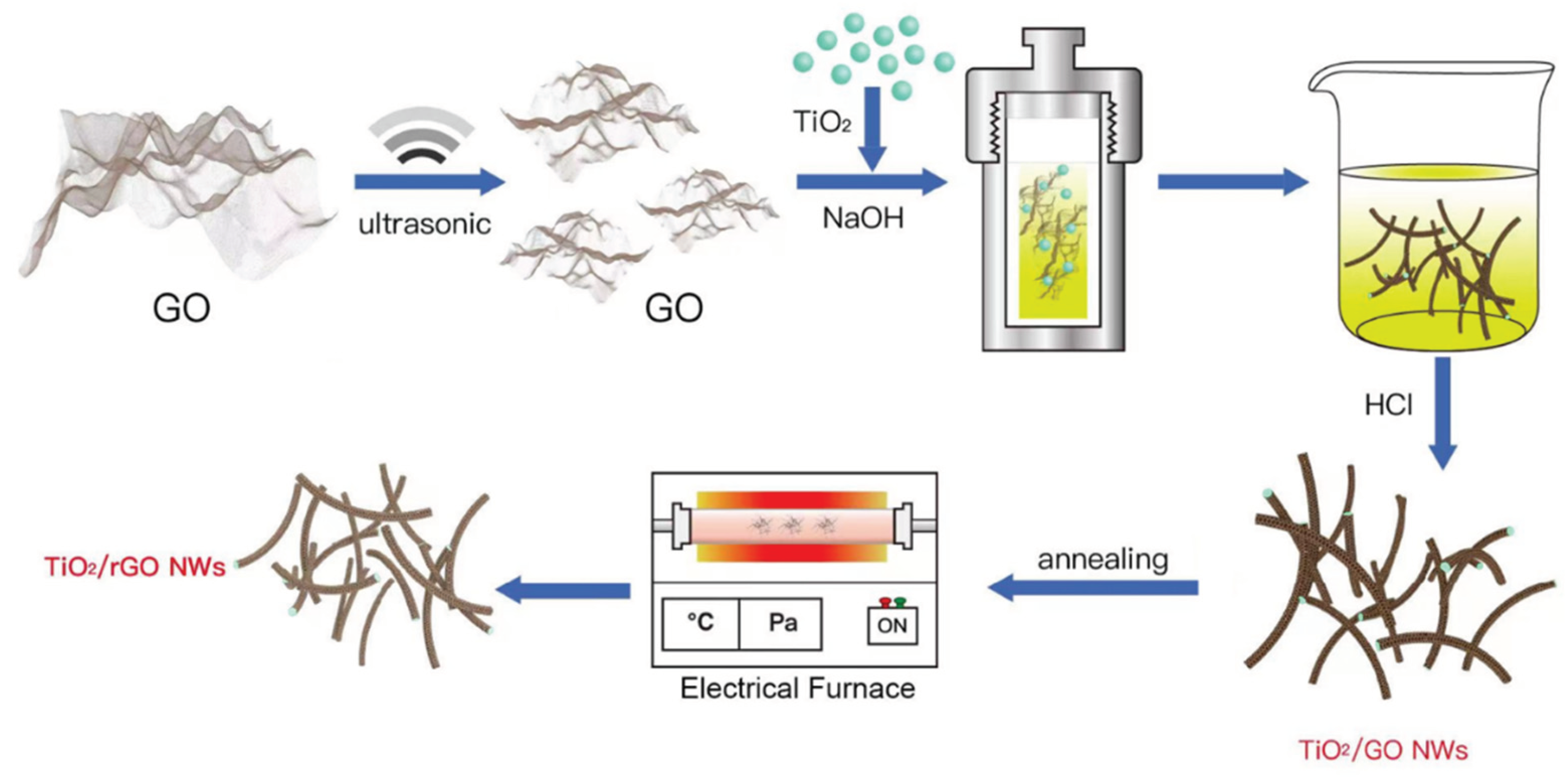
The process of synthesizing Titanate/GO NWs and Titanate/rGO NWs is clearly illustrated in
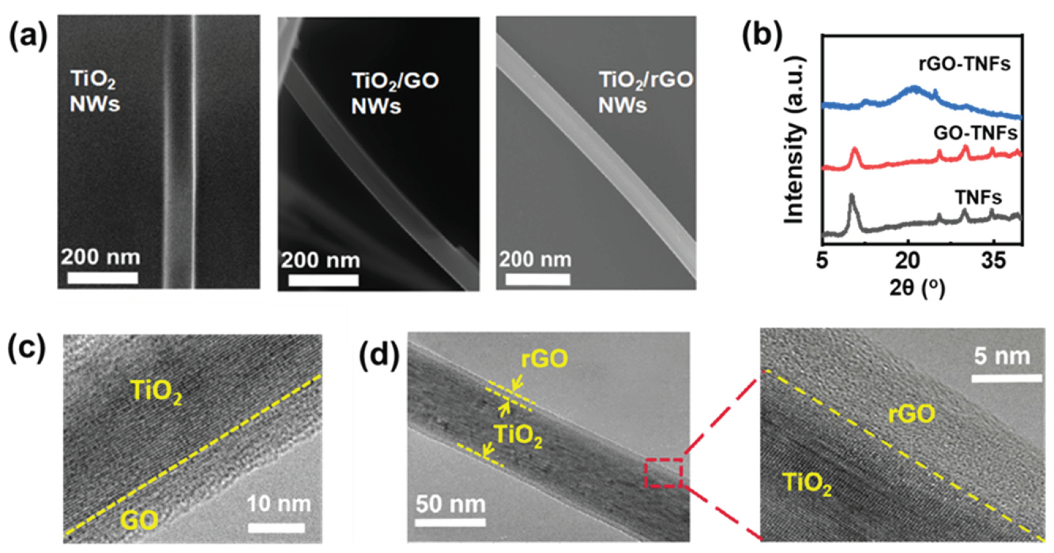
Schematic 1. Initially, Titanate/GO NWs with a core-shell structure were formed hydrothermally by suspending GO and titania powders in NaOH aqueous solution, then reduced to rGO-Titanate NWs at elevated temperatures in the Ar gas environment, with approximately 35-40 μm in length and 60 nm in diameter with a smooth surface and uniform distribution, as shown in
Figure 1 (a) and
Figure S2. The energy dispersive X-ray (EDX) spectrum in
Figure S2 (a
2) confirmed the elemental components of Ti and O, with a small amount of background C present on the specimen, and that of Si from the substrate that supports the specimen. The annealing method in an inert gas atmosphere has been proven in the literature to be a simple and effective way to reduce GO to rGO. Moreover, the SAED pattern in
Figure S3 revealed the mixed diffraction patterns of the crystalline titanate. The X-ray diffraction (XRD) peaks of titanate NWs (
Figure 1 (b)) at 9.8°, 11.2°, 24.4°, and 29.7° can be assigned to (001), (200), (110), and (003), respectively (JCPDS card No.: 47-0561).[
29] Evidently, a broad peak at 18 - 30° can be attributed to the amorphous phase of rGO, indicating that the GO-titanate NWs have been successfully and effectively reduced to rGO-Titanate NWs by the calcination in the inert gas atmosphere.[
30] As shown in
Figure 1 (c) and (d), the rGO shell thickness of rGO-titanate NWs was reduced from 10 nm to approximately 6 nm, and the morphology was unchanged during the calcination.
Schematic 1.
The process to make rGO-Titanate nanowires.
Schematic 1.
The process to make rGO-Titanate nanowires.
Figure 1.
(a) SEM images of titanate, GO-titanate, and rGO-titanate nanowires. (b) XRD of titanate, GO-titanate, and rGO-titanate nanowires. (c) and (d) the TEM images for GO-titanate and rGO-Titanate nanowires.
Figure 1.
(a) SEM images of titanate, GO-titanate, and rGO-titanate nanowires. (b) XRD of titanate, GO-titanate, and rGO-titanate nanowires. (c) and (d) the TEM images for GO-titanate and rGO-Titanate nanowires.
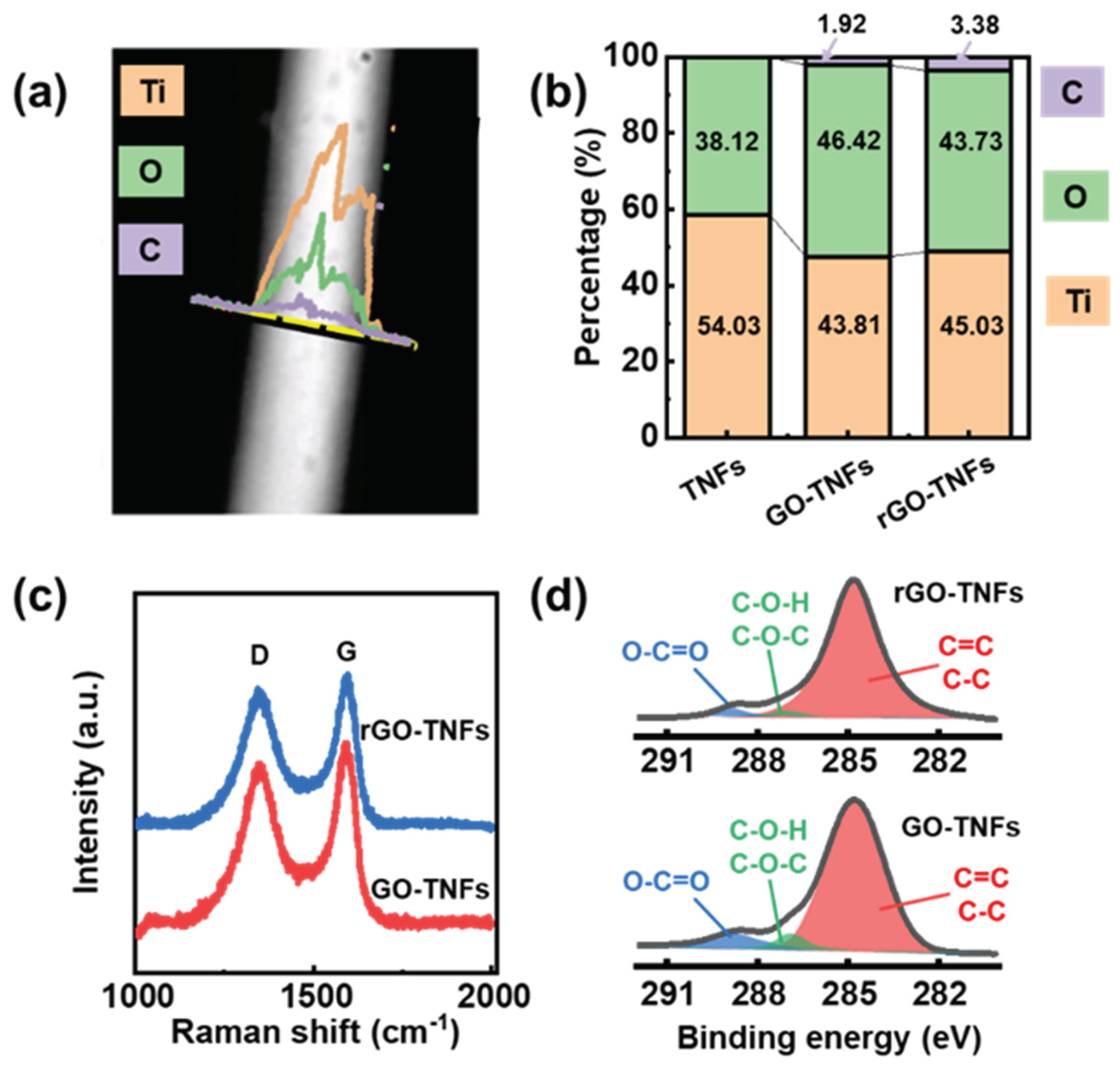
On this basis, the core-shell NWs were analyzed using the EDX, FTIR spectroscopy, XPS and microRaman techniques to further confirm that the GO on titanate NWs was successfully reduced to rGO. From the EDX elemental analysis data in
Figure 2 (a) and (b), the O element ratio decreased from 46.42% (for the GO-Titanate NWs) to 43.73% (for the rGO-Titanate NWs), while the C ratio increased from 1.92% to 3.38%. Consistently, the FTIR peaks in
Figure S4 displayed the IR spectra of the samples. The broad and strong absorption band at 400 - 700 (cm
−1) belonged to the stretching vibration of Ti-O-Ti and Ti-O. The bands at 930 and 1250 (cm
−1) were attributed to the C-O and C-OH groups, respectively, while the band at 1720 - 1750 (cm
−1) was from the carbonyl groups on the GO and rGO edge. The peak at 1630 (cm
−1) was ascribed to the C=O bonds and deformation vibrations of the absorbed water. The peak at 2900 cm
−1 corresponded to the stretching and bending vibrations of hydroxyl group in the basal plane and the edge, and the broad band from 3300 to 3500 (cm
−1) was from the surface hydroxyl group or the absorbed water molecules. On the TiO
2/rGO NWs, these modes from the oxygen-containing functional groups were mostly diminished, which supports the reduction of GO to rGO, which is in line with others’ reports[
31]. The microRaman spectra of the samples are presented in
Figure S5. The peaks at 142, 194, 400, 517, and 645 cm
-1 correspond to the Raman modes of Eg
(1), Eg
(2), B1g
(1), A1g+B1g
(2), and Eg
(3) of the titanate, respectively. Additionally, two broad bands were observed at approximately 1348 cm
-1 and 1592 cm
-1 (
Figure 2 (c)), which were attributed to the disordered amorphous carbon attributed to the disordered amorphous (the D band) and graphitic sp
2 carbon (the G band). The ID/IG ratio was approximately 0.9 (with ID and IG correspond to the intensity of the D band and G band, respectively), which confirmed the presence of the GO or rGO layer on TiO
2 NWs. The low content of GO or rGO in the hybrid composites resulted in no significant shift of the D band and G band. In parallel, the XPS was employed to analyze the element chemical state. The spectra demonstrated the presence of O, Ti, and C in the Titanate NWs, Titanate/GO NWs, and Titanate/rGO NWs (
Figure S6). The O 1s spectra exhibited two distinct peaks. Specifically, for Titanate NWs, the two peaks at 531.2 eV and 529.9 eV can be attributed to the C-O and Ti-O groups, respectively. The incorporation of GO and rGO shells results in a blue shift of the Ti-O band at 530.1 eV, indicating the interaction and binding between the GO (rGO)-shell and the Titanate-core. In the C 1s spectra (
Figure 2 (d)), there are three distinct peaks: the 284.7 (eV) from the C-C and C=C, the 286.8 (eV) from C-O-C and C-O-H, and the 288.6 (eV) from O-C=O and C-O-Ti, respectively. Apparently, the C-O-C, C-O-H, O-C=O, and C-O-Ti peaks of the rGO-titanate NWs were reduced significantly compared with those of the GO-titanate NWs. Based on the EDX, FTIR and XPS data, the GO was largely reduced to the rGO during the calcination, and titanate nanowires were well wrapped with the GO or rGO, which agreed with the XRD and Raman analyses.
Figure S6 (c) showed the Ti 2p spectra of all the specimens, indicating that the titanium elements in the samples were in the form of Ti
4+ value, as evidenced by the energy difference between Ti 2p
3/2 and Ti 2p
1/2 peaks of 5.7 eV. Comparing Titanate NWs with Titanate/GO and Titanate/rGO NWs, the GO and rGO shells caused a blue shift of 0.3 eV and 0.1 eV, respectively for the two bands, implying chemical bonding between the core and the shell. Overall, the XPS data provided a new insight into the elemental composition and chemical state of the specimens, revealing the interaction and binding between the core and shell.
Figure 2.
(a) EDX spectra of rGO-titanate nanowires. (b) EDX element ratios of C, O, and Ti for titanate, GO-titanate, and rGO-titanate nanowires. (c) Raman spectroscopy of GO-titanate and rGO-titanate nanowires. (d) XPS spectroscopy of GO-titanate and rGO-titanate nanowires.
Figure 2.
(a) EDX spectra of rGO-titanate nanowires. (b) EDX element ratios of C, O, and Ti for titanate, GO-titanate, and rGO-titanate nanowires. (c) Raman spectroscopy of GO-titanate and rGO-titanate nanowires. (d) XPS spectroscopy of GO-titanate and rGO-titanate nanowires.
To further support the photocatalysis performance of NWs, the optoelectronic properties were characterized by means of the UV-Vis absorption and photocurrent response experiments, which are supported using the finite element analysis-based theoretical simulation. The theoretical analysis indicates that the oxidation level of GO is related to the GO bandgap nature.[
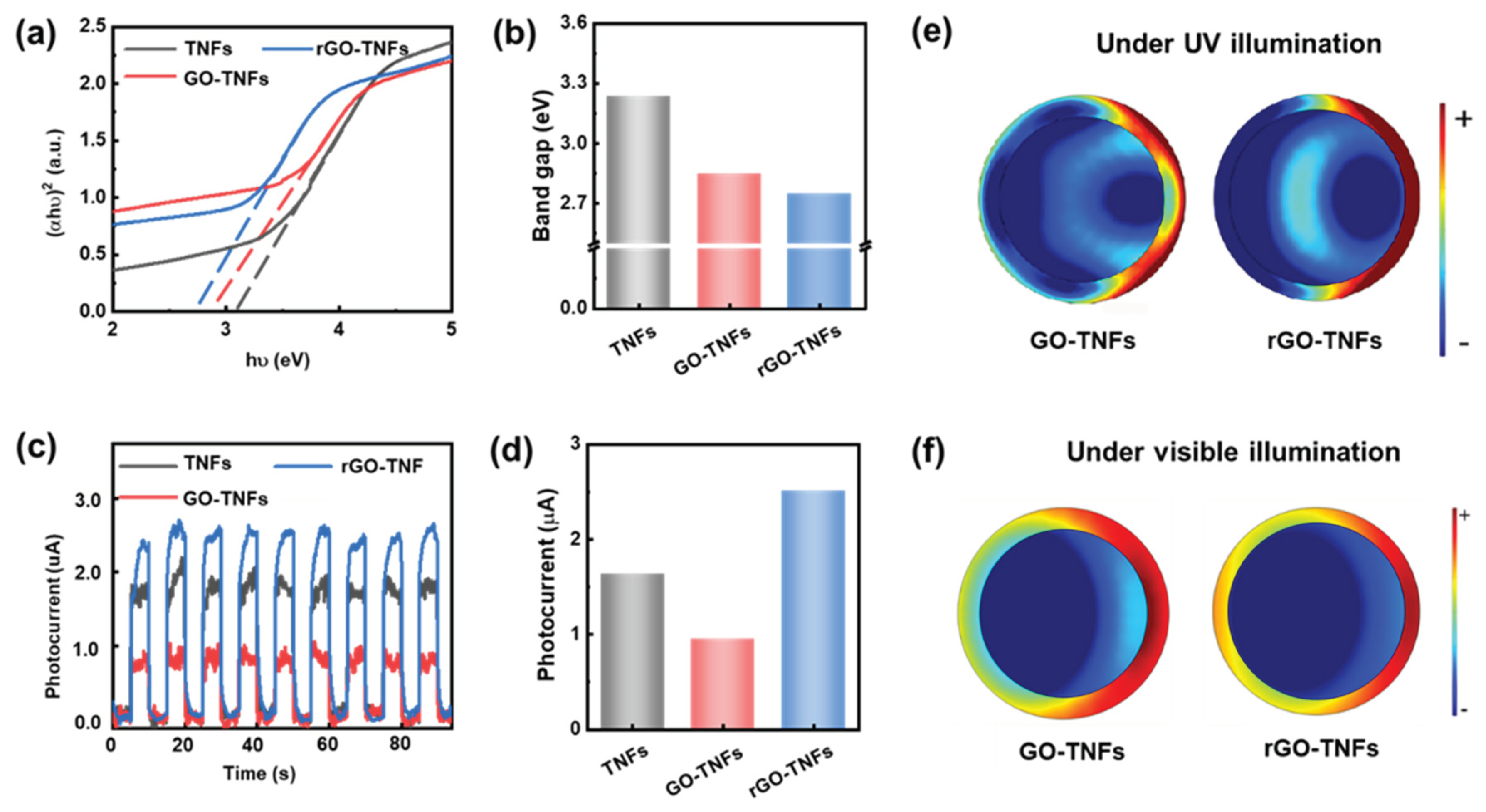
17] GO is a non-crystalline material with different oxidation-containing functional groups, so a sharp adsorption edge with a precise bandgap energy cannot be observed in the conversion plots. Therein, the Tauc plots derived from the UV-vis absorption spectra were employed to determine the NW bandgap (as depicted in
Figure 3 (a) and (b)), showing the rGO-titanate NW’s bandgap was significantly reduced to 2.75 eV (vs. titanate’s 3.23 eV and GO-titanate 2.98 eV), which further expanded the light absorption range of wavelengths to improve the photocatalytic performance. As shown by the UV-vis absorption spectra of the specimens in
Figure S7, where the absorption in the ultraviolet region for all the samples confirmed the band absorption of anatase TiO
2. Moreover, the rGO flakes, Titanate, and Titanate/rGO core/shell were further characterized by hyper spectrometer imaging (HIS) in the visible and near-IR (NIR) wavelengths from 400 nm to 1000 nm (
Figure S8), revealing the absorption of Titanate/rGO to be significantly greater more than that of Titanate NWs. This new HIS data suggest that the core/shell nanocomposite of Titanate/rGO can help better utilize the diffusive solar energy in the photocatalysis. The increased sunlight absorption might generate more electron-hole pairs, thereby leading to improved photoresponse and photocatalytic performance.
The photocurrent response of the nanocomposites under intermittent UV light was shown in Figure 3 (c) and (d), where all the photoanodes exhibit a rapid photoresponse and as the photocurrent (which is almost negligible in the dark) increases instantly to its maximum within 0.1 – 0.2 s upon exposure to light. The photocurrent of rGO-titanate is about 4 and 1.3 times greater than that for GO-titanate and titanate NWs, respectively. The reduction in the photocurrent for Titanate/GO NWs is attributed to the insulating characteristics of the GO layer, whereas the increase in the photocurrent for Titanate/rGO NWs is apparently due to the conductive properties and suppression of charge recombination by the rGO layer. These findings are consistent with the bandgap variation in Figure 3(b). To further understand the active photoresponse and photocatalytic behavior, the charge distribution of the NWs under the light irradiation was studied by the finite element analysis, providing the charge density at the cross section of the NWs under the incident light (254 and 420 nm, respectively), as illustrated in Figure 3 (e) and (f). Intuitively, the negative charges should be confined to the naked cations on the titanate core surface, allowing the positive charges to be dissipated along the rGO shell more quickly than that along the GO shell. This could explain why the photocurrent charges’ separation on the rGO-titanate being better than that on the GO coated NWs, which boosted the photocatalysis performance of the rGO-titanate.
Figure 3.
(a) Tauc plots of the UV-Vis absorbance spectra for titanate, GO-titanate, and rGO-titanate nanowires. (b) The bandgap of titanate, GO-titanate, and rGO-titanate nanowires from Tauc plot. (c) and (d) photocurrent responses curves and average values. (e) and (f) Charge distribution of the nanowires as induced by the UV and Visible light.
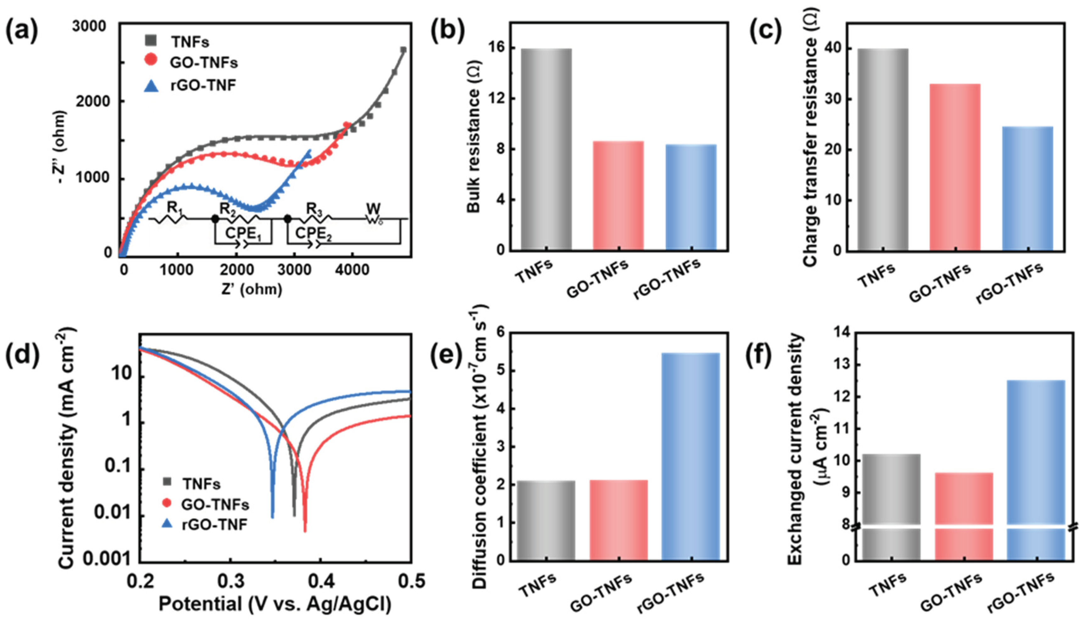
To enhance our understanding of the charge transfer kinetics and physiochemical properties of the NWs, electrochemical methods were employed. The Nyquist plots of the impedance spectra in
Figure 4 (a) were fitted well with an equivalent circuit to obtain the bulk resistances and charge transfer resistances of the NWs. The bulk resistances of GO-titanate and rGO-titanate NWs (
Figure 4 (b)) were significantly decreased compared with the pure titanate NWs, because of the conductivity improvement from the reduction of GO. As shown in
Figure 4 (c), there was a progressive decrease in the charge transfer resistances from the titanate to the GO-titanate and to the rGO-titanate NWs, indicating the rGO coating significantly enhance the photocatalysis performance by accelerating the charge transfer rate across the interface between the solid nanowire surface and liquid solutions.
Table 1 presents the pore size, volume, and surface area obtained from N
2 adsorption–desorption isotherms of the specimens depicted in
Figure S9. Furthermore,
Figure S9 showed that Titanate/GO NWs had the largest specific surface area of 15.32 m
2/g, which improves 23% over Titanate NWs and was attributed to the high specific surface area of the GO layer. However, the annealing decreased the specific surface area, presumably due to the collapse of the three-dimensional porous structure. From a chemical perspective, the weakened inter-bonding of the rGO flakes (much weaker than that of the GO flakes) could minimize the 3D-stacking of the NW/rGO type of 1D-nanocomposites, which matched their pore size and pore volume. Nevertheless, the surface area of Titanate/rGO NWs (14.55 m
2/g) was still larger than that of pure Titanate NWs (12.50 m
2/g), which could provide more active sites for dye molecule absorption and photocatalytic degradation. Meanwhile, the rGO shell on the NWs provides a large surface area with lots of defects and dangling bonds (
Figure 4e) to better the dye molecules physical adsorption and kinetic mass-transfer[
32] and efficiently boosting the photocatalysis kinetics. Evidently, the energy barrier of charge transfer on the rGO-titanate NWs was significantly decreased by reducing the reversible potential and increasing the exchanged current density, with respect to that on the pure titanate and the GO-titanate NWs, as shown in the
Figure 4 (d) and (f), which further helped the charge transfer process and improved the photocatalysis efficiency.
Figure 4.
(a) Nyquist plots of the impedance spectra for titanate, GO-titanate, and rGO-titanate nanowires and (b) the values of bulk resistance and (c) the charge transfer resistance. (d) Tafel plot of titanate, GO-titanate, and rGO-titanate nanowires and the values of (e) Diffusion coefficient and (f) exchanged current density.
Table 1.
Structural parameters of the specimens as achieved from the N
2 adsorption–desorption isotherm in
Figure S9.
Table 1.
Structural parameters of the specimens as achieved from the N
2 adsorption–desorption isotherm in
Figure S9.
| |
TiO2 |
TiO2/GO |
TiO2/rGO |
| Pore size (nm) |
11.84 |
10.95 |
11.27 |
| Pore volume (cm³/g) |
0.036982 |
0.041934 |
0.040996 |
| Surface area (m²/g) |
12.50 |
15.32 |
14.55 |
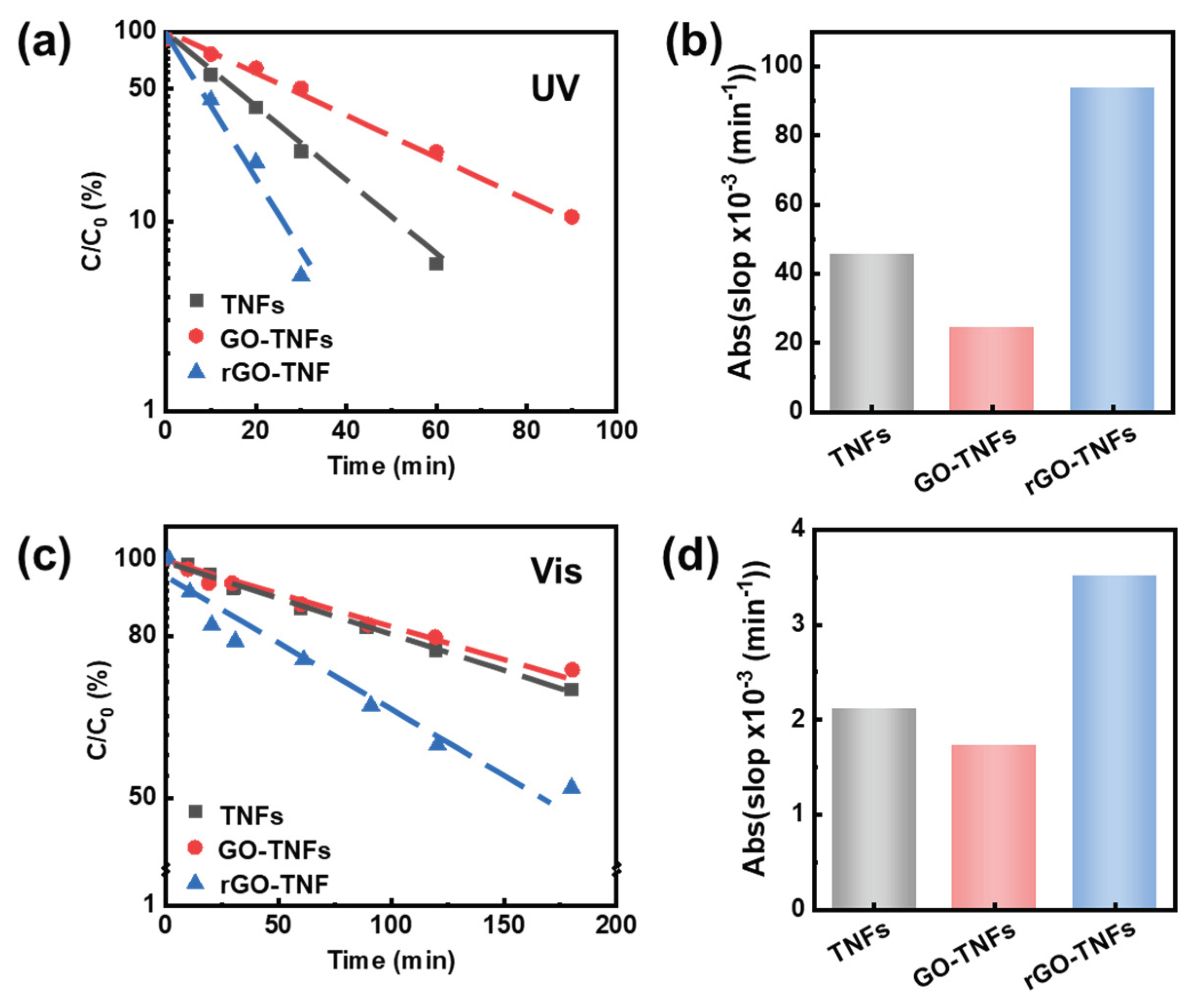
To assess photocatalytic activity of the specimens, the degradation of methylene blue (MB) dyes as catalyzed by the specimens under both visible and UV light, was carried out. The intensity of the absorption band of the MB aqueous solutions continuously decreases with increasing irradiation time (see Figure S10), indicating the photocatalytic ability of all the TiO2-based specimens. Figure 5 (a) presented the logarithmic percentage of the residual dye molecules were linearly fitted with the UV illumination time, indicating that the MB degradation process was the first-order kinetic process. The rGO-titanate core-shell exhibits the most effective photocatalytic performance (Figure 5(b)). Notably, compared with titanate NWs and GO-titanate NWs under visible illumination, the photocatalytic performance of rGO-titanate core-shell NW for MB degradation under UV light was significantly improved (Figure 5 (c) and (d)). This time the dye solution is completely bleached in ~ 30 min by the Titanate/rGO, 60 min by the Titanate NWs, and >90 min by the Titanate/GO. This confirms the best photocatalytic activity of the NW/rGO, by design.
Figure 5.
(a) First-order linear plot of C/C0 versus time of MB degradation with logarithmic y coordinate under UV illumination. (b) Absolute values of slops from first-order linear plot under UV light. (c) First-order linear plot of C/C0 versus time of MB degradation with logarithmic y coordinate under visible illumination. (d) Absolute values of slopes from first-order linear plot under visible light.
Mechanistically, the novel structure and well-integrated surface chemistry and physics resulted in the high kinetic charge transportation, low surface energy barrier, and large surface area for the rGO-titanate NW to enhance the dye molecules sorption and mass transfer to boost the dye photocatalytic degradation (Figure. S11). Evidently, the tight bonding between the conductive rGO shell and wide bandgap titanate NW core has facilitated the photo-excited charges separation, docking and transport. The excited photoelectrons migrated to the graphene surface via the bonding between the rGO and titanate, letting the rGO act as an electron acceptor to effectively suppress the charge recombination. The photoelectrons could also be scavenged by O2 to produce reactive superoxide radicals (•O2−), while the holes can be trapped by H2O to produce hydroxyl radicals (•OH), docking on the core (to quench the quick combination), and react with (or decompose) the dye molecules, which should be verified using future experimental measurements in the follow-up work.
