1. Introduction
The production process of building materials such as steel bars and cement generates a large amount of carbon and harmful gas emissions [
1], exacerbating global climate issues such as climate change and environmental pollution, promoting natural building materials can help alleviate these problems. Bamboo and wood are two common natural building materials that have been widely used in construction projects, where bamboo has higher carbon sequestration efficiency [
1] and better mechanical properties than wood [
2,
3]. A series of studies and engineering examples have proved the feasibility of bamboo as a building material [
4,
5]. Compared with engineered bamboo, raw bamboo culms do not require the use of adhesives and are more environmentally friendly as a building material.
The different cross-sectional geometries of natural bamboo culms, the anisotropy of bamboo materials, the different mechanical properties of different parts of the same bamboo culm [
6], and the different orientations of different joints connecting different bamboo tubes in the bamboo tube structure constrain the standardization of the design of the bamboo tube structures and bring difficulties to the promotion of the bamboo tube structure. Hong et al. [
7] divided the common bamboo tube connection joints into two categories of traditional joints and modern joints, where the traditional joints include tied connections and mortise and tenon connections, and the modern joints include types such as bolts, steel components, and fillers. In the German-Chinese House at the Shanghai World Expo 2010 [
8], the joints are made of steel prefabricated parts with grouting, and the prefabricated steel components are capable of connecting bamboo tubes in different directions. Huang et al. [
9] proposed a bamboo tube joint using grouting and built-in steel sheet connection, and the tests showed that this type of joint has high load bearing capacity. The above improved grouted joints showed better mechanical properties, but the grouting would significantly increase the self-weight of the structure and could not take advantage of the light weight of the bamboo tube structure. Richard et al. [
10] proposed a new type of joint connecting bamboo tubes with steel rings and pieces, and the stiffness and strength of this type of joint were proved to be more than that of the traditional grouted bamboo tube joint through tests. Benoit et al. [
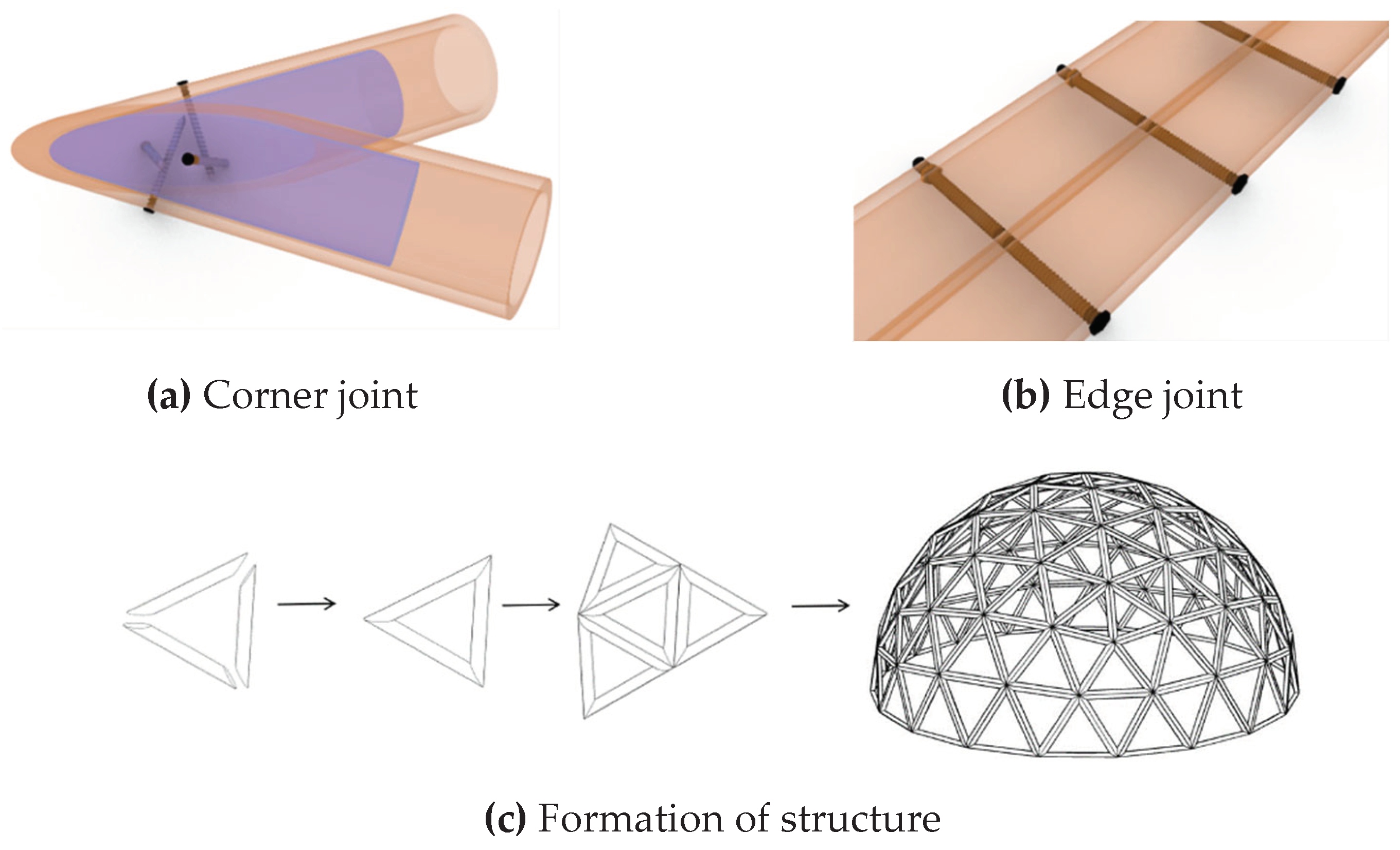
11] proposed a bamboo tube joint using a combination of wood plugs and metal clamps, and demonstrated through experiments and numerical simulations that the joint can be used for the longitudinal extension of bamboo tubes with good strength, providing a new idea for lightweight joints of bamboo tube structures. In this paper, a lightweight joint for cross connection of bamboo tubes is proposed as shown in
Figure 1a, where wood plugs are embedded in each of the two sides of the bamboo tubes, and each screw is screwed from the outside of one side of the bamboo tube into the wood plug inside the other side of the bamboo tube, and the bamboo tube and the wood plugs are cut at the same angle in the joint part. The joint has the advantages of light weight, easy production, and low cost.
The existing bamboo tube space structures can be divided into two types: [
12,
13] bamboo tube arch structure and bamboo tube lattice structure. Bend and connect one or more long bamboo tubes to form a large-span bamboo tube arch structure, the disadvantage is that the bending process using manual labor makes it difficult to control processing accuracy. The bamboo tube lattice structure uses straight bamboo tubes, which are easy to process and low in cost, but the processing difficulty of multi-directional joints and the customization cost is high. Zhuo et al. [
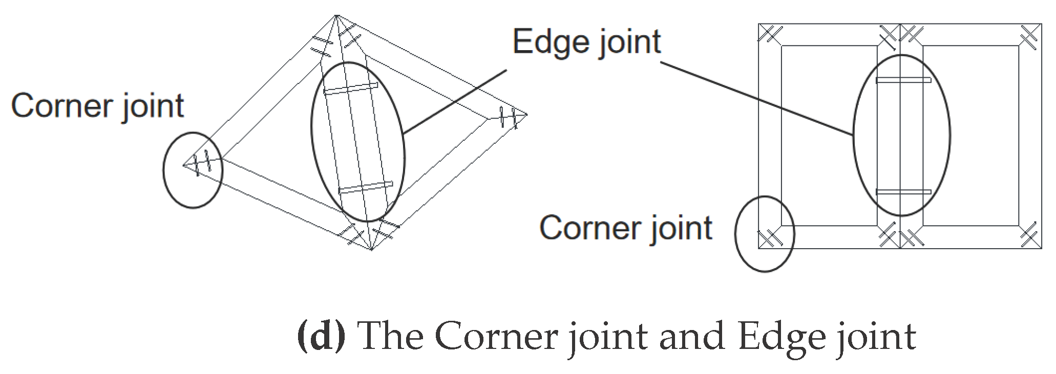
14,
15] proposed a framed bamboo culm grid structure system(Frame-unit prefabricated bamboo culm structure), the formation principle is shown in Figures 1c and 1d: straight bamboo culms are assembled into bamboo culm frame units, which can be in polygonal geometries such as triangles, rectangles, trapezoids, hexagons, and other polygonal geometries; the joints of neighboring culms are called corner joints, which can be connected by a combination of grouting, screws, and wood plugs (
Figure 1a); and the joints between neighboring bamboo culm frames are called edge joints, which use bolts as connectors (
Figure 1b).
After all the bamboo culm frame units are connected, the overall structure can be formed. This paper employs experimental, numerical simulation, and theoretical analysis to investigate the flexural performance of frame-unit bamboo culm joints. The focus is on studying the semi-rigid bearing mechanism and calculation method for joints when materials are in the elastic phase at edge and corner joints
2. Bamboo Culm Frame Specimen Bending Performance Test
2.1. Overview of the Test
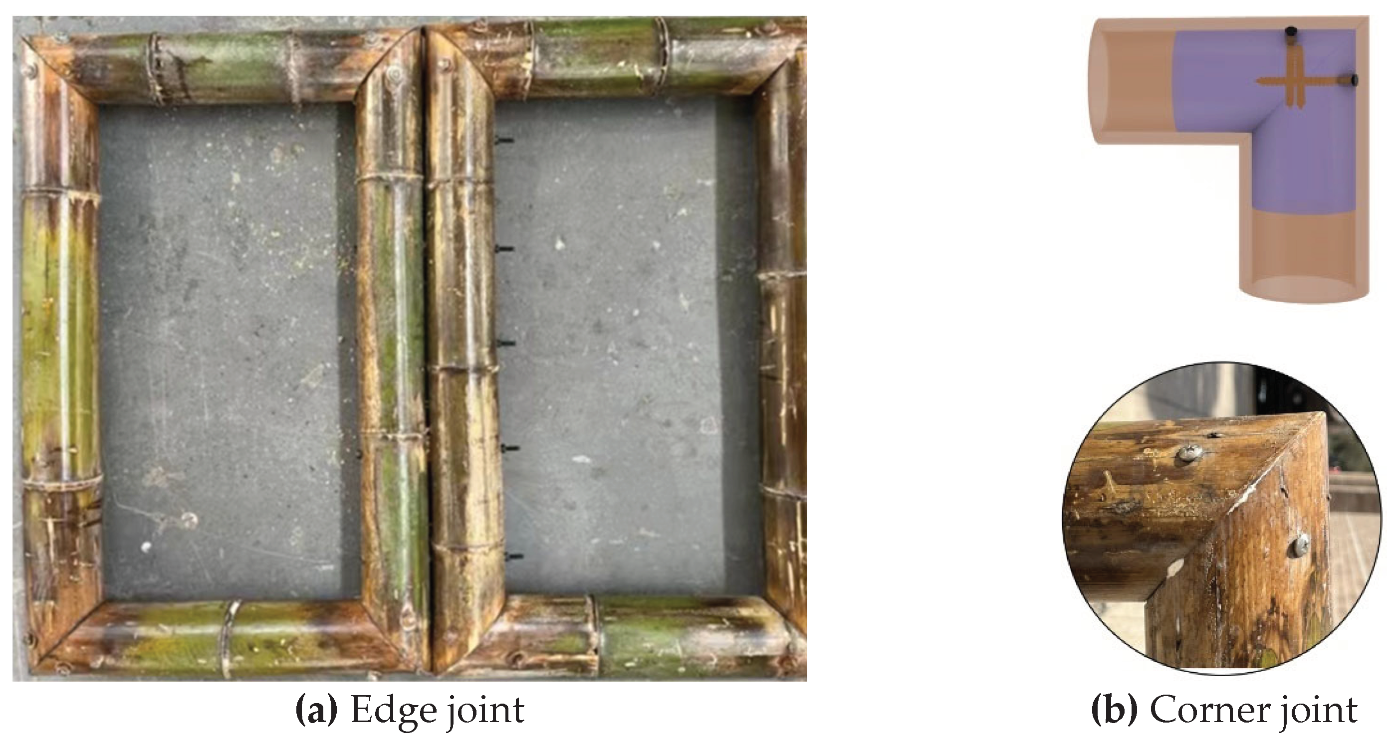
In this paper, the specimens were assembled by two neighboring rectangular bamboo culm frames connected by bolts (
Figure 2a), with the diameter of the bamboo culms ranging from 75 mm to 95 mm and the wall thickness ranging from 7.5 mm to 8.5 mm. The corner joints of the bamboo culm frames were embedded with wood plugs inside and were connected using four 4mm diameter screws (
Figure 2b). The edge joints are made of Q235 bolts with a diameter of 10 mm and a length of about 200 mm.
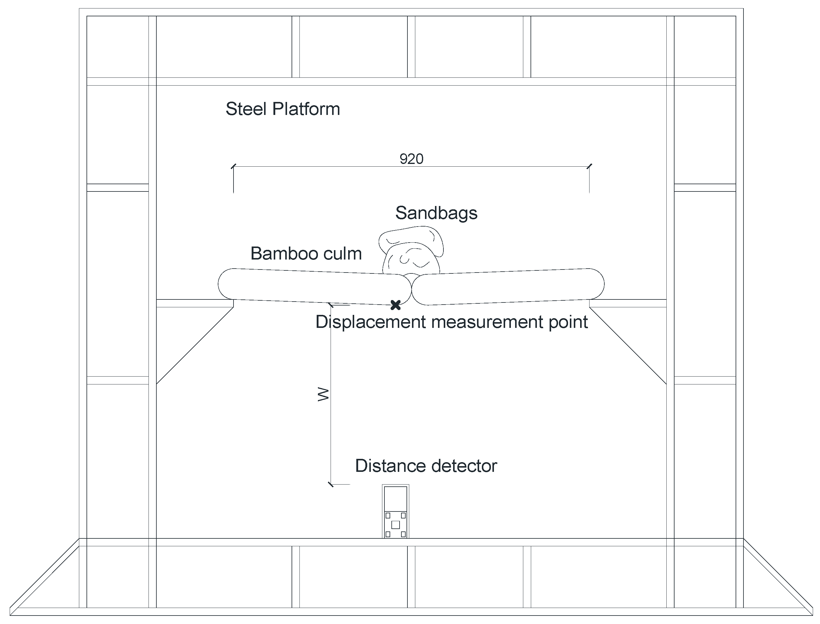
The specimens were rested in a simply supported manner on the bull legs of the steel frame test rig (shown in
Figure 3).
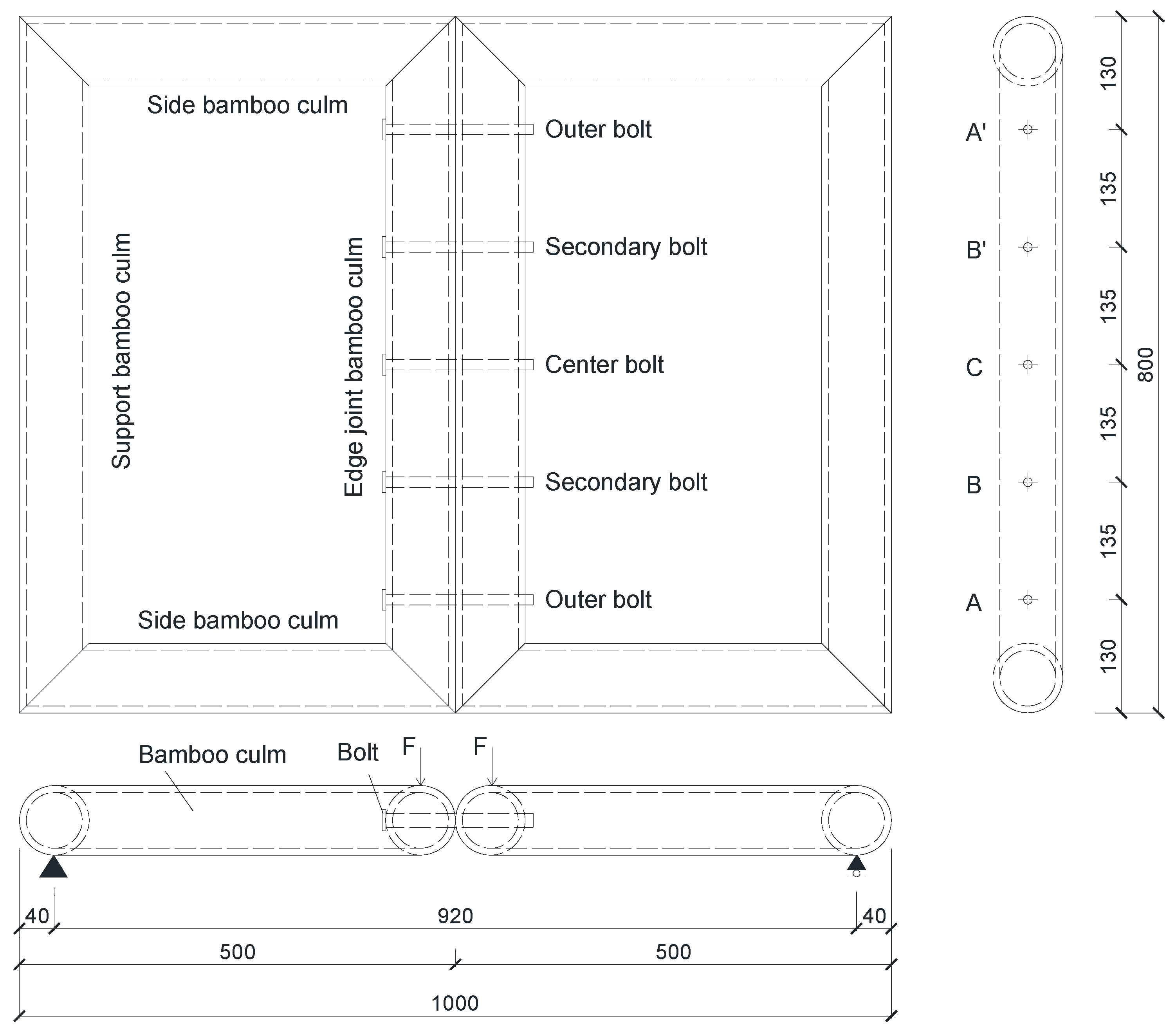
The positions of bolt holes are marked as A, B, C, B’, A’ respectively. The dimensions of the assembled specimens are shown in
Figure 4. Loading tests were conducted on specimens with 2, 3, and 5 bolts connected to the edge joints, the experimental parameters for each model are shown in
Table 1 The specimen number “Sn” indicates that the number of bolts in the edge joint is n.
2.2. Experimental Process and Result Analysis.
The two bamboo culm frames of the specimen are in the same plane when unloaded. Loading is done by stacking sandbags, with each sandbag weighing 10kg (±0.5kg). The loading position is in the middle of the specimen (
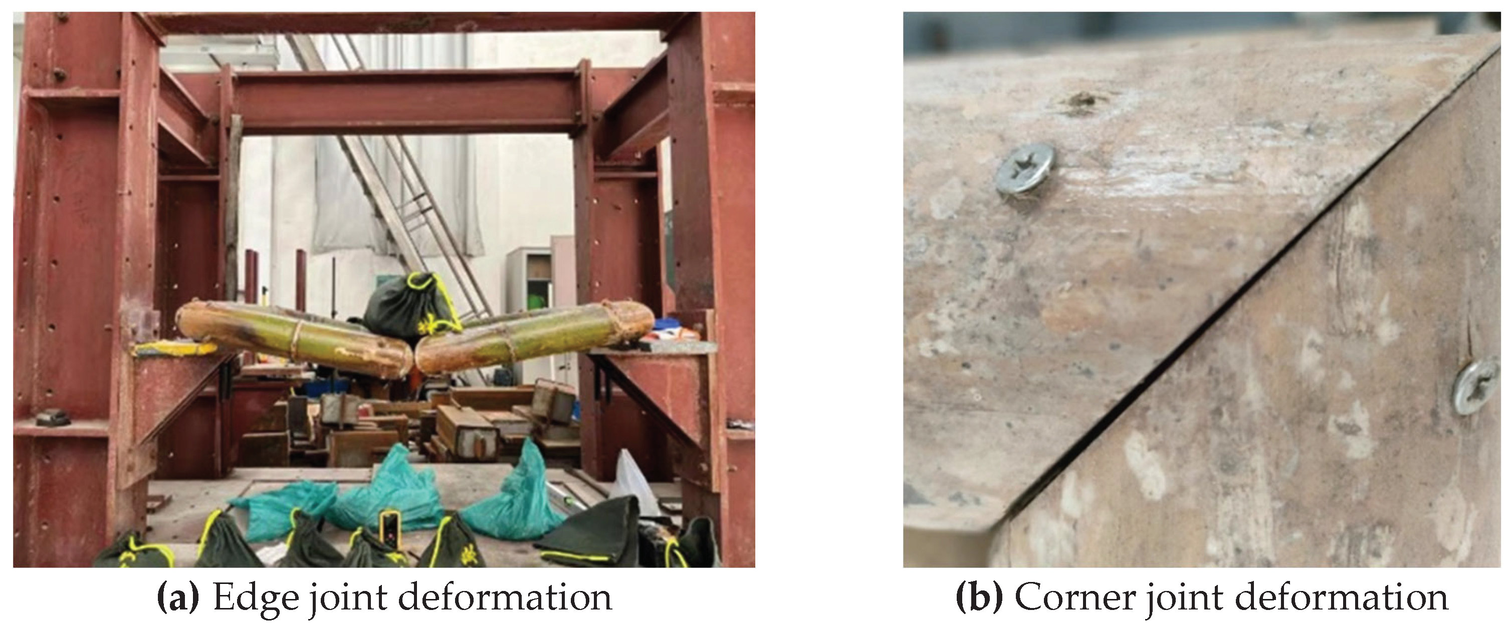
Figure 3). Vertical displacement occurs at the edge joint positions of the specimen, gradually increasing with the number of sandbags (
Figure 5a), and there’s a gap between the two bamboo culms at the corner joint (
Figure 5b). The measuring point for vertical displacement is at the midpoint of the lower edge of the edge joint bamboo culm (
Figure 3), measured using a laser distance detector with an accuracy of 0.1mm. During loading, sandbags are placed one by one, and data from the displacement detector is read only after the vertical displacement stabilizes after placing a sandbag (the unloading stage is similar). The deflection of the measuring point under each stage of loading is:
where
is the reading at stage i, and
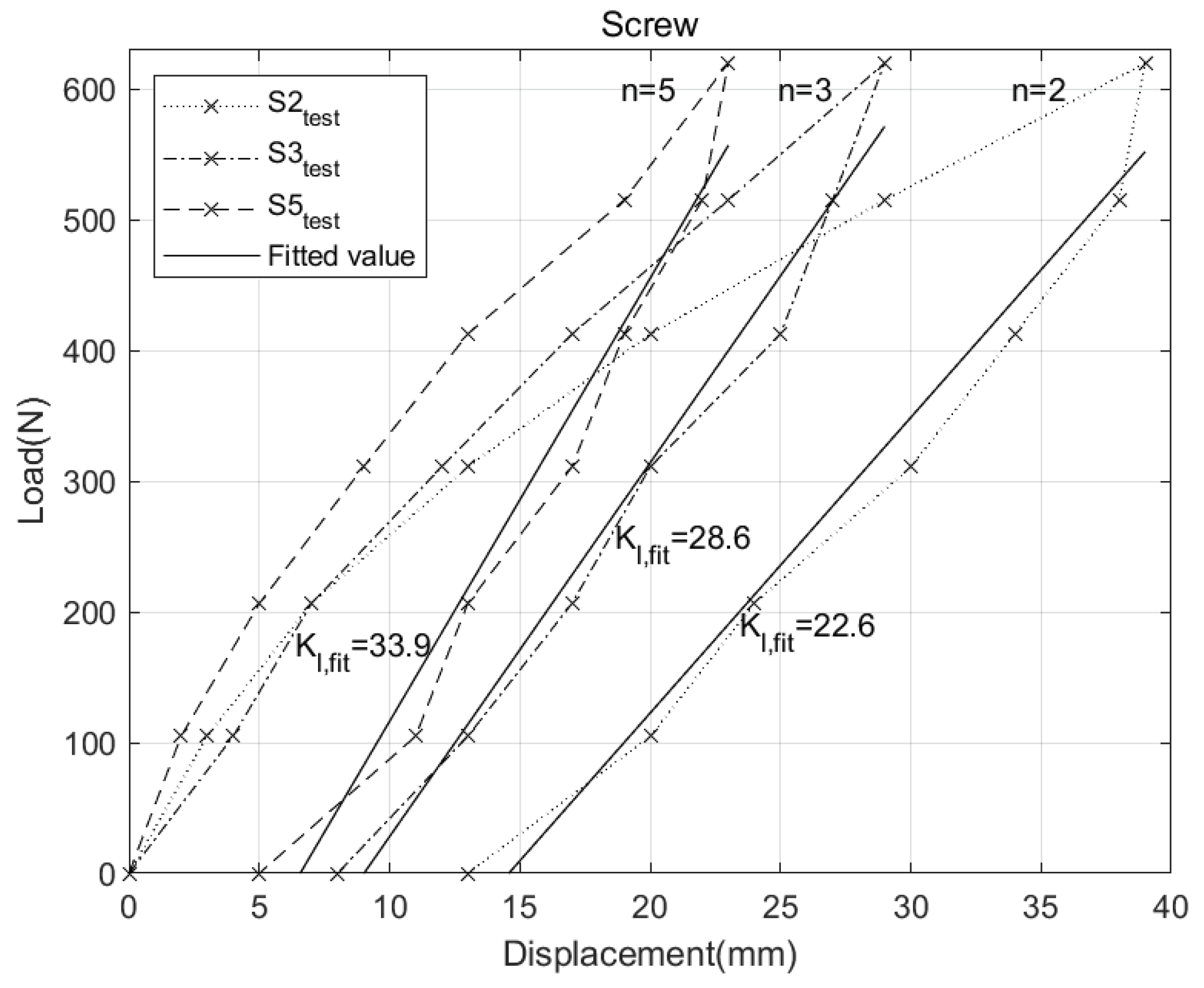
is the reading without load. The data recorded at each loading step is used to create the load-displacement relationship shown in
Figure 6.
Before loading, due to the presence of bamboo nodes, it is impossible to achieve complete fit between the outer walls of adjacent bamboo culms. In addition, it is also impossible to achieve a complete fit between the bamboo culm bolt hole wall and the bolt thread, so the deformation during the loading process includes measurement errors caused by these factors. In contrast, the unloading process has achieved close contact between different materials, and the corresponding load-displacement relationship can better reflect the true mechanical properties of the specimens.
The total bending linear stiffness
(hereafter referred to as total linear stiffness) of the bamboo culm frame in the elastic phase is defined as the ratio of the out-of-plane load at the edge joints to the vertical displacement occurring in the direction of action:
where ∆
F and ∆
d are the incremental load and displacement of the measuring point.
The test data from the unloading stage were selected for linear fitting (using the polyfit function in MATLAB) to obtain the fitted values of total linear stiffness
(
Figure 6), which shows that the total bending linear stiffness is positively correlated with the number of bolts. However, as the number of bolts increases, the efficiency of stiffness increases decreases gradually.
2.3. Synergistic Relationship between Corner Joints and Edge Joints.
During the loading process, no visible bending occurred in each bamboo culm, while vertical displacement occurred at the edge joints. At the same time, the gap at the corner joints gradually widened with the increase of the load (
Figure 5b), indicating that the corner joints and edge joints are not completely rigid (semi-rigid). Define
and
as the rotational stiffness of the edge joints and corner joints, respectively:
where
are the bending moments and turning angles of the edge joints,
are the bending moments and turning angles of the corner joints, and the units of bending moments and turning angles are
, respectively.
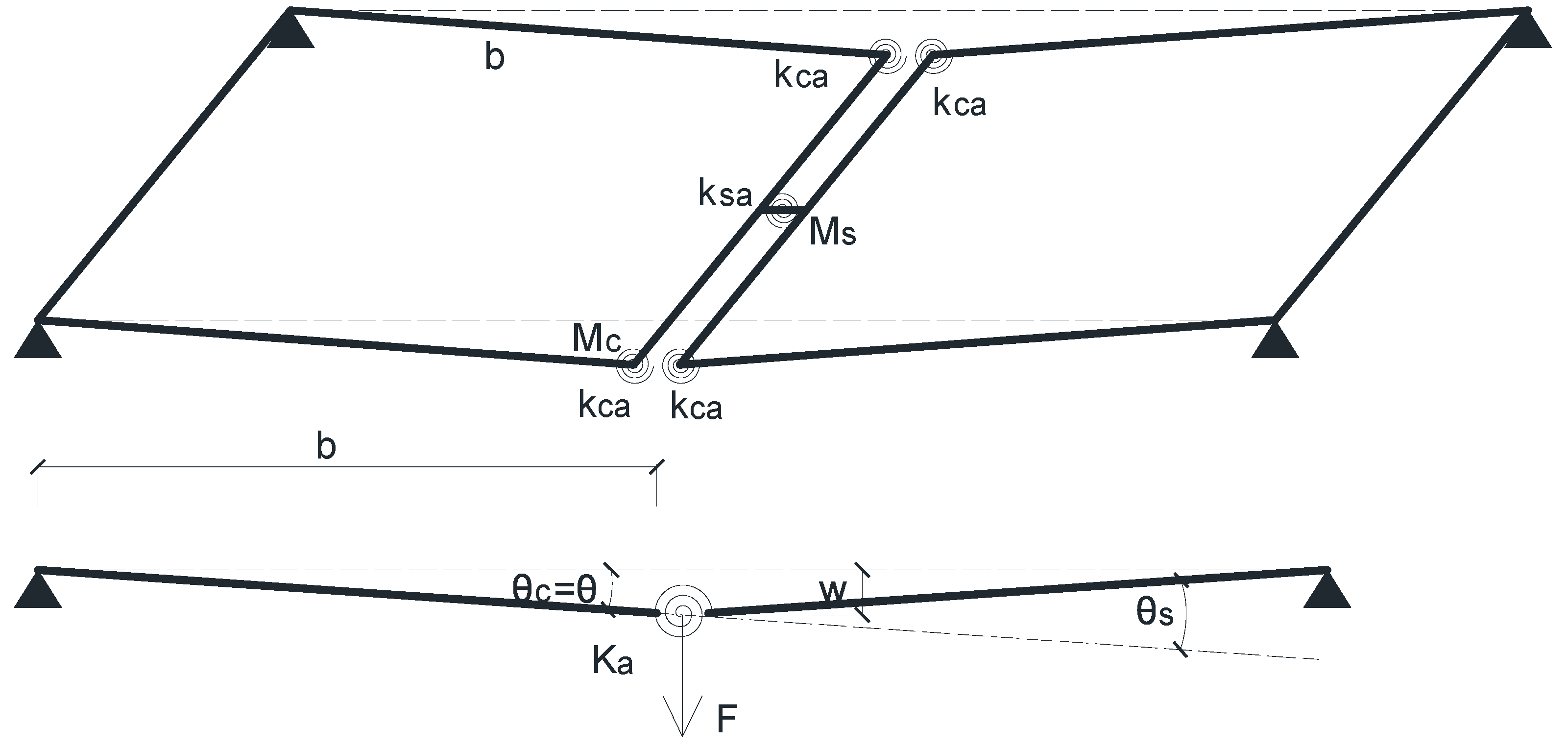
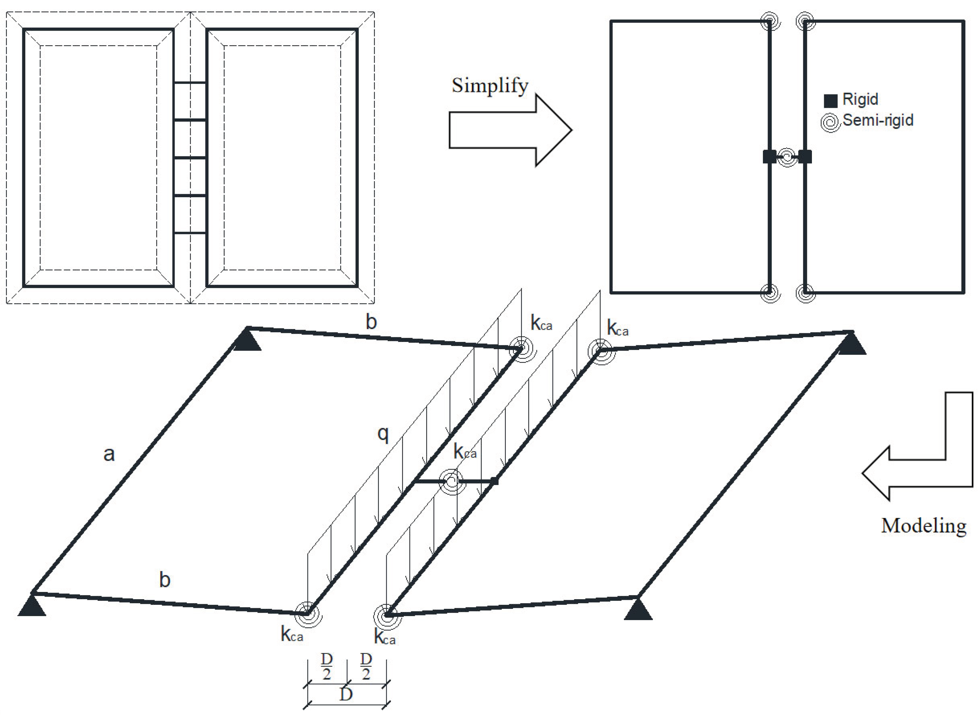
To convert the relationship between force and displacement into the relationship between bending moment and rotation, the various bamboo culms are simplified into rigid members, and a simplified diagram for the internal force calculation of the frame-unit bamboo culm members shown in
Figure 7 is established.
In
Figure 7, F is the vertical force acting on the upper surface of the edge joint bamboo culm. Under the action of F, both the edge joint and the corner joints produce vertical displacement.
When the corner joints are completely rigid, define the edge joint linear stiffness:
When the edge joint is completely rigid, define the corner joint linear stiffness:
According to
Figure 7:
where: b is the distance between the axis of edge joint bamboo culm and support bamboo culm (hereinafter referred to as the shear span). When the structural deformation is small:
The numerator and denominator in equation 3 are represented by ∆
F and ∆
w respectively, the relationship between the edge joint linear stiffness and its rotational stiffness can be obtained:
Similarly, the relationship between the corner joint linear stiffness and its rotational stiffness can be obtained from equation 4:
The unit of edge and corner joint linear stiffness is N/mm. From equations 5 and 6, the linear stiffness is not a property of the joint itself, and its value is related to structural parameters such as rotational stiffness and span.
In structural mechanics, the shear distribution method is solved by analyzing the series-parallel relationship and stiffness relationship of the members [
16]. In the structure shown in
Figure 7, the two corner joints in a bamboo culm frame single-sided structure are in parallel relationship, and the relationship between the corner joints and the edge joint constitutes a series relationship, and the series and parallel relationships of the assembled joints are shown in
Figure 8:
According to
Figure 8, establish the relationship between the overall rotational stiffness and that of the edge and corner joints.
Similarly, the relationship between total linear stiffness and the linear stiffness of the edge and corner joints can be established:
3. Numerical Simulation
3.1. Overview
3.1.1. Setting of Numerical Simulation
The finite element software Abaqus is used for modelling and calculation of numerical simulation. Since the two neighboring bamboo culm frames have symmetry, in order to improve the computational efficiency, only a single bamboo culm frame is established, and symmetrical constraints are applied to the mid-span cross sections of truncated bolts;
The influence of bamboo nodes is not taken into account;
The actual bamboo culm wall has different elastic modulus along the axial, lateral and radial directions, which is simplified by setting up bamboo culms as orthotropy material in both axial and lateral directions, and ignoring the difference in the mechanical parameters of the bamboo culms along the radial direction;
The diameter of the opening of the bamboo culm is the same as the diameter of the bolt, which is taken as 10 mm, ignoring the effect of the thread on the bamboo culm;
The loading plate for applying load is set to simulate the sandbag load in the test.
3.1.2. Material Properties
According to the test data of García et al. [
17], the mechanical properties of bamboo are shown in
Table 2, where: direction 2 is the bamboo culm axis (fiber) direction, and directions 1 and 3 are perpendicular to the axis direction (the bamboo culm material property setting direction is the local coordinate system of the bamboo culm). E
mn, V
mn, and G
mn are the elastic modulus, Poisson’s ratio, and shear modulus. The yield strength of the bolt is 235MPa, the elastic modulus is 206GPa, and the Poisson’s ratio v is 0.3; according to the axial compression test conducted by Zhang et al. [
18,
19], the axial compressive yield strength is 50.3Mpa, and the shear yield strength is 25Mpa. The compressive strength σ
c of the bamboo culm groove is calculated according to the formula proposed by Peng Hui et al. [
20]:
where: F
s is the yield load of bearing compression of bolt hole, σ
1 is the compressive strength of bamboo culm with grain, d is the diameter of the hole, and t is the thickness of the bamboo culm. Rewrite equation 14, can get the compressive strength of bamboo culm at the location of the bolt hole wall:
3.1.3. Calculation Model
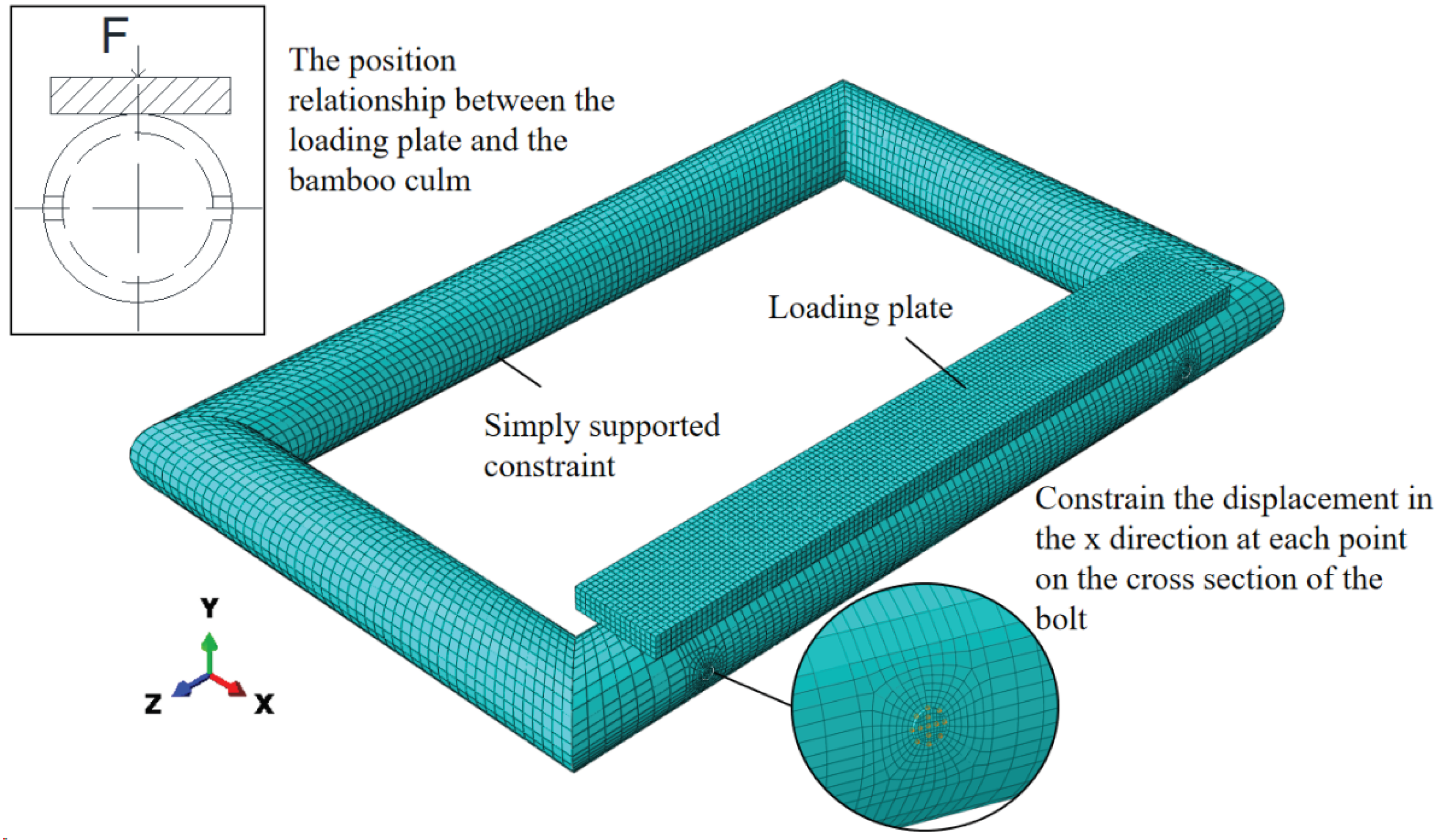
The friction coefficient between the bolt and the wall of the bamboo culm is set at 0.3; the normal direction is set as “hard contact”, and only pressure is transmitted between them. The loading plate is set as a rigid body, The friction coefficient between its lower face and the bamboo culm is set at 0, loading plate transmits pressure only. (does not play the role of a member).
The model numbers and bolt positions of the numerical simulation are the same as
Table 1. The outer diameter of the bamboo culm is 80mm, and the wall thickness is 8mm. The components include bamboo culms, and bolts (
Figure 9), with the bamboo culms consisting of edge joint bamboo culm, support bamboo culm and side bamboo culms, all dimensions of the components are consistent with
Figure 4. The support bamboo culm is set as a simply supported constraint, restricting the displacement in the y and z directions at various points on its lower edge, and constraining the displacement in the x direction at various points on the cross-section of the bolt midspan. The mesh type used is C3D8R. To be consistent with the experiment, the loading range of the edge joint bamboo culm does not include the beveled area at the end of the bamboo culm. A gradually increasing concentrated force is applied to the upper surface of the loading plate until one of the bolts yields.
3.2. Semi-Rigid Corner Joint
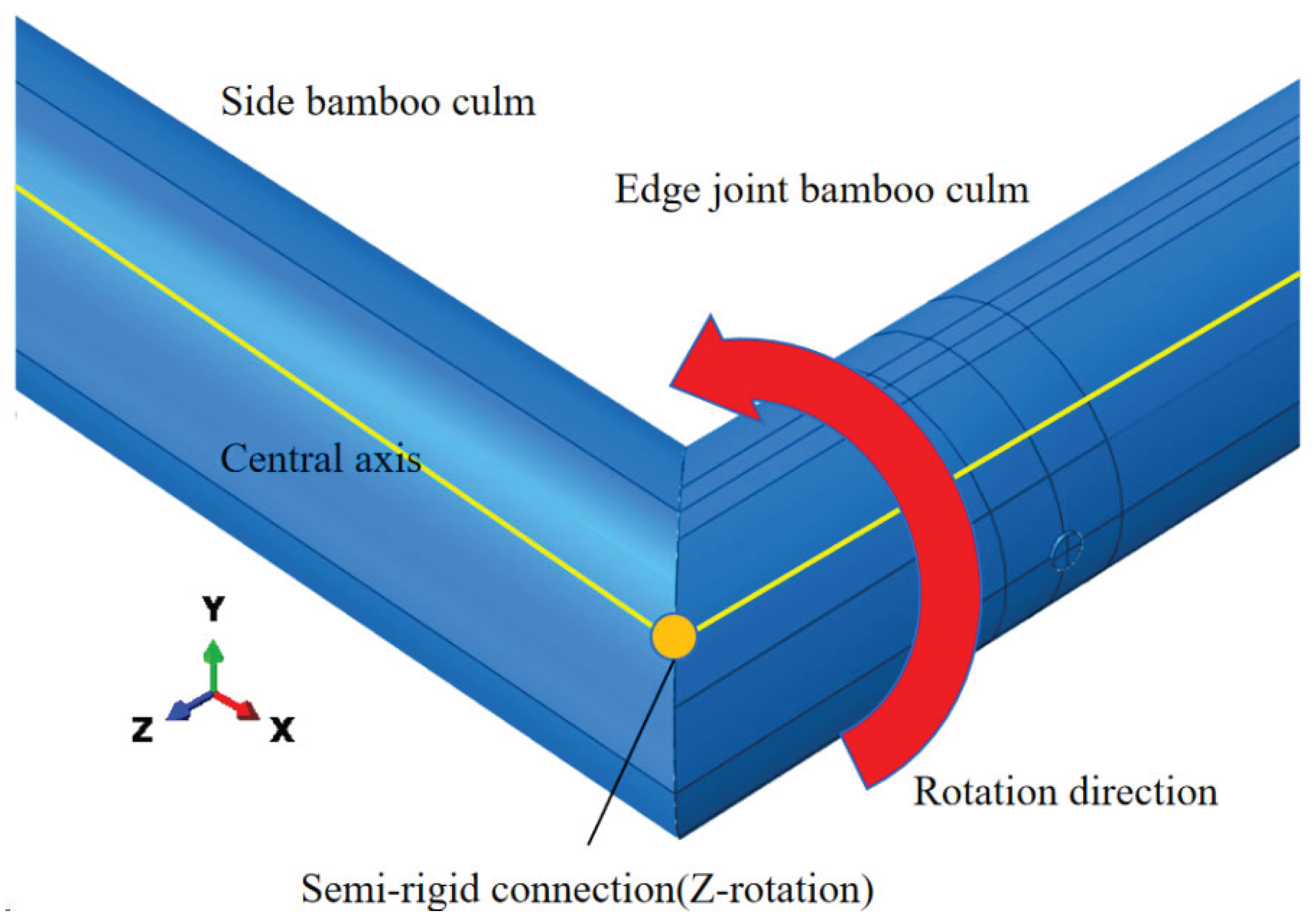
Due to the complexity of the forces in the corner joint area of the bamboo culm frame, the corner joints in the numerical simulation will be modelled and calculated as full rigidity and semi-rigidity respectively.
3.2.1. Set the Corner Joint to Be Fully Rigid.
The end faces of the neighboring bamboo culms are set into coupling constraints, and the relative angle between the end faces of the side bamboo culms and the end faces of the edge joint bamboo culms is maintained at 0. To study the deformation of the structure when the materials are all in the elastic phase, extract the yield loads for each model from the post-processing module of the numerical simulation. When the loads were 245N, 330N and 460N respectively, the bolts of the models with the number of bolts at the edge joints of 2, 3 and 5 yielded respectively. Currently, no plastic deformation occurs at both bolt holes and bamboo culm walls. The cross-sections of each bolt span were subjected to bending moment around the Z-axis direction, and the proportion of the bending moment of each bolt is shown in
Table 3.
The vertical displacements of the displacement measurement points corresponding to the experiment are recorded as and for 50N and 100N loads, respectively.
The total linear stiffness value
of the structure when the corner joint is fully rigid is calculated according to equation.16, and the fitted value
is obtained according to the test data, both of which are shown in
Table 4, which shows that there is a big difference between numerical simulation and test values when the corner joint is set to be fully rigid, it is therefore necessary to change the setting of the corner joint to be semi-rigid.
According to equation.13, the total linear stiffness is the edge joint linear stiffness when the corner joint stiffness is infinite:
3.2.1. Setting Corner Joints to Semi-Rigid.
The steps to modify the corner joints to be semi-rigid are as follows:
Removing coupling constraints at the corner joint (
Figure 10) and replace it with a semi-rigid joint rotating in the direction of the Z-axis (spring constraint);
The corner joint rotational stiffness
was assigned different values and substituted into the numerical simulation model to obtain the values of total linear stiffness
considering the semi-rigid corner joints (
Table 5).
Comparing the values of
corresponding to
Table 4 and
Table 5, the effect of the semi-rigidity of the corner joints on the total linear stiffness of the structure can be seen.
By equation.11, the value assigned to
above is converted to
, and substituting into equation.13 can calculate the total linear stiffness
(consider the semi-rigidity of corner joints,
Table 5), where
is obtained from equation.17 (
in
Table 4). Plotting the data in
Table 5 as
Figure 11, the numerical simulation fits very well with the calculated values of equation.13, proving the feasibility and accuracy of replacing numerical simulation with equation.13.
The values of linear stiffness
for the considered semi-rigid corner joints can be obtained by bringing the first and second rows of
Table 4 into equation.13 as
and
, respectively. the value of
after substituting into equation.11 is transformed into the value of
as shown in
Table 6. This value is the average rotational stiffness of the four corner joints connecting the edge joints in
Figure 7, not the rotational stiffness of the corner joints in a specific certain position.
3.3. Semi-Rigid Edge Joint
To analyze the effect of positions on the stiffness of the edge joints when the number of bolts is the same, s is defined as the distance from the outermost bolt to the axis of the side bamboo culm (Defined as “side distance”,
Figure 12), and
is the linear stiffness of the edge joint as a function of s, the bolts arranged at equal distances. Through the numerical simulation method established in this paper, the
corresponding to different values of s can be obtained, as shown in
Table 7. The linear regression equations of
and s are established:
where: A and B are coefficients to be determined.
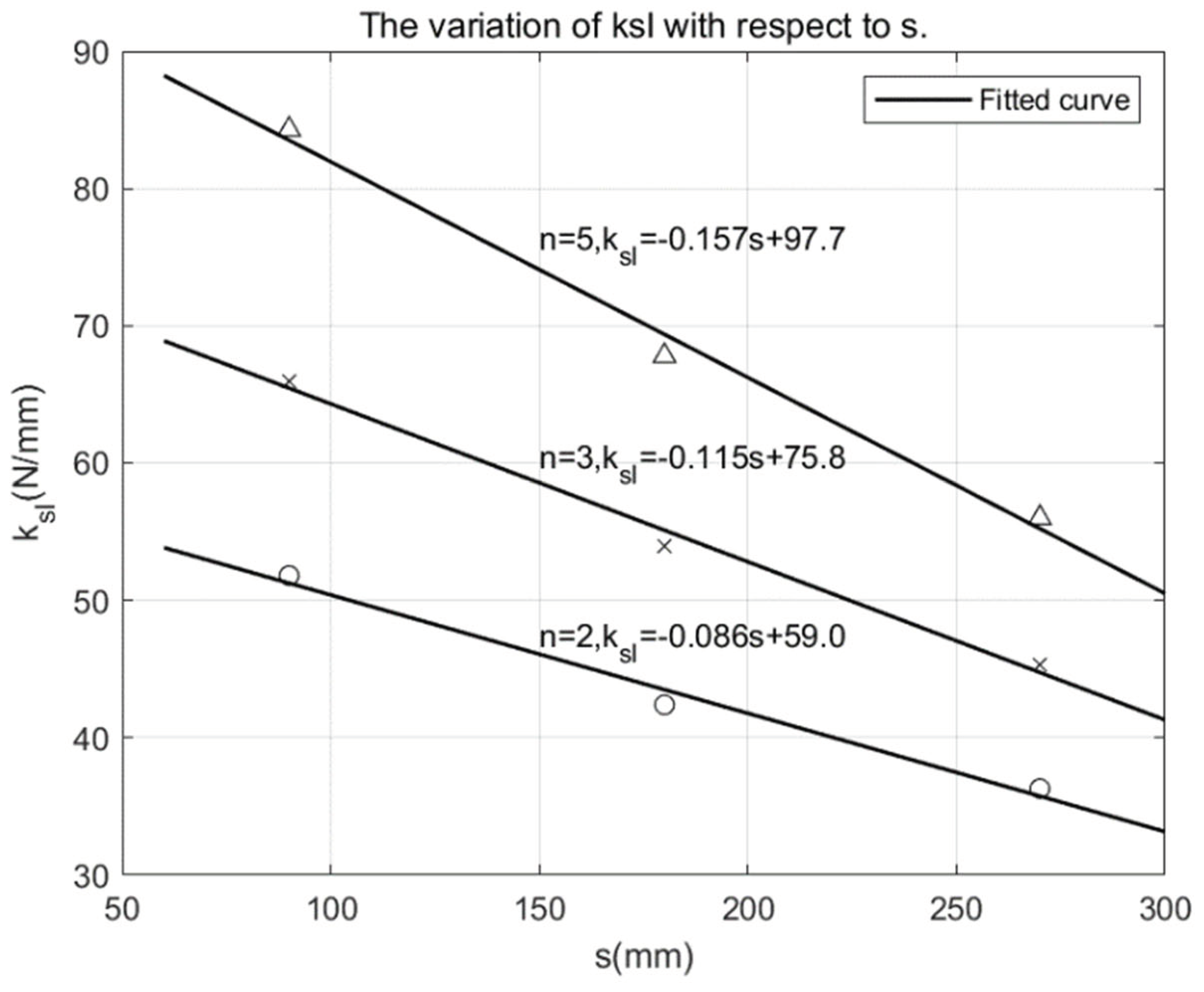
Matlab is used to linearly fit the (
) points of
Table 7 according to equation.18, the
relationship can be obtained for different numbers of bolts, see
Figure 13. The stiffness values calculated from the fitted relationship equation have an error of less than 3% compared to the stiffness values obtained from the numerical simulation, which indicates that the regression effect is good. It is also found that under the condition of the same number of bolts,
increases linearly with the decrease of s, which indicates that the outer bolt closer to the corner joint is more beneficial for stiffness improvement.
By substituting the fitting equation in
Figure 13 and b=420mm into equation.10, the calculation formula for the rotational stiffness of the edge joint can be obtained when the diameter of the bolts in the edge joint is set to 10mm.
From equation.3 and 4, the rotational stiffness of the joint is the relative angle of rotation produced under the action of unit bending moment, which is a property of the joint itself. Therefore, equation.19 is a general formula for the rotational stiffness of the corner joint when the diameter of the bolts of the edge joint are 10 mm. Similarly, the rotational stiffness values
in
Table 6 are generic values for corner joints in a specific configuration (using 4 screws combined with wooden plugs). These values and formulas derived from experimental data, numerical simulations and theoretical derivations provide a basis for the setting of joint semi-stiffness in structural finite element analyses.
4. Finite Element Analysis of Structures and Design Methods for Components
The finite element analysis method of the structure is to model the components according to the axes, and since the calculation formulas and parameters obtained in Chapter 3 of this paper are based on solid modelling, a practical method for the finite element analysis and component design of the bamboo culm and frame-unit bamboo culm structure will be presented in this chapter. The equivalent joint forces and joint deformations in the structure are first analyzed according to the computational model in
Figure 7, and then the internal forces of the bamboo culm and bolts are calculated in combination with the computational model, then the allowable stresses and deformations of each component are verified.
Taking the model shown in
Figure 4 as an example, the material, size and number of bolts of the two bamboo culm frame units are the same as those of the S5test in the test, i.e., : the outer diameter D of the bamboo culm is 80mm, the thickness of the bamboo wall t is 8mm, and the size of the outer frame of the bamboo culm frame: L×H=800mm×500mm (axial figure: a=720mm, b=420mm). The edge joint is connected by 5 bolts with d=10mm, the side distance s is 90mm, and the rest of the bolts are arranged in equal distance from each other. The corner joints are connected by 4 screws and wooden plugs. The support bamboo culm is used as the simply supported side. The top of the edge joint bamboo culm is subjected to a uniform load, and the total force F is consistent with the experimental value in
Figure 6, which is taken as 413N.
4.1. Structural Finite Element Analysis Methods
4.1.1. Structural Modelling
The equivalent computational model of each member is shown in
Figure 14:
Select the axis of each bamboo culm as the position of the equivalent members;
An equivalent bolt is set at the midpoint of the edge joint bamboo culm, and the connection between the equivalent bolt and the edge joint bamboo culm is a rigid connection. The middle position of the equivalent bolt is disconnected, and the disconnection is set as a semi-rigid connection;
All corner joints are set to semi-rigid connections;
The two ends of the support bamboo culms are set as hinged.
4.1.2. Parameter Settings
Since the corner and edge joint stiffnesses studied in this paper already include the deformation of the material itself, to avoid repeated calculations, the members should be set as rigid bodies during the finite element analysis of the structure, i.e., : the stiffness and elastic modulus of various materials are set to infinity. The semi-rigid joints are set as follows:
From
Table 6, the rotational stiffness of the corner joints:
From equation.19, the edge joint rotational stiffness:
Taking the test data at n=5 in
Figure 6 when the load is 413 N, the uniform load on the edge joint bamboo culms:
4.1.3. Calculation Result
The maximum deflection obtained by using Abaqus is 12.2 mm, while the measured value of the test in
Figure 6 is 13.0 mm, which indicates that the calculation method in this paper has a good calculation accuracy.
4.2. Design Methods for Components
4.2.1. Internal Force Distribution
The software calculates the maximum bending moment on the equivalent edge joint bolt to be , which is the value of the combined cross sectional internal force in the mid-span of each bolt in the actual structure, so this equivalent joint force needs to be assigned to each bolt.
The bending moment at the equivalent edge joint was distributed to each bolt according to the distribution ratio coefficients in
Table 3, and the values of bending moments on the five bolts were obtained as 2.24, 1.47, 1.27, 1.47, 2.24
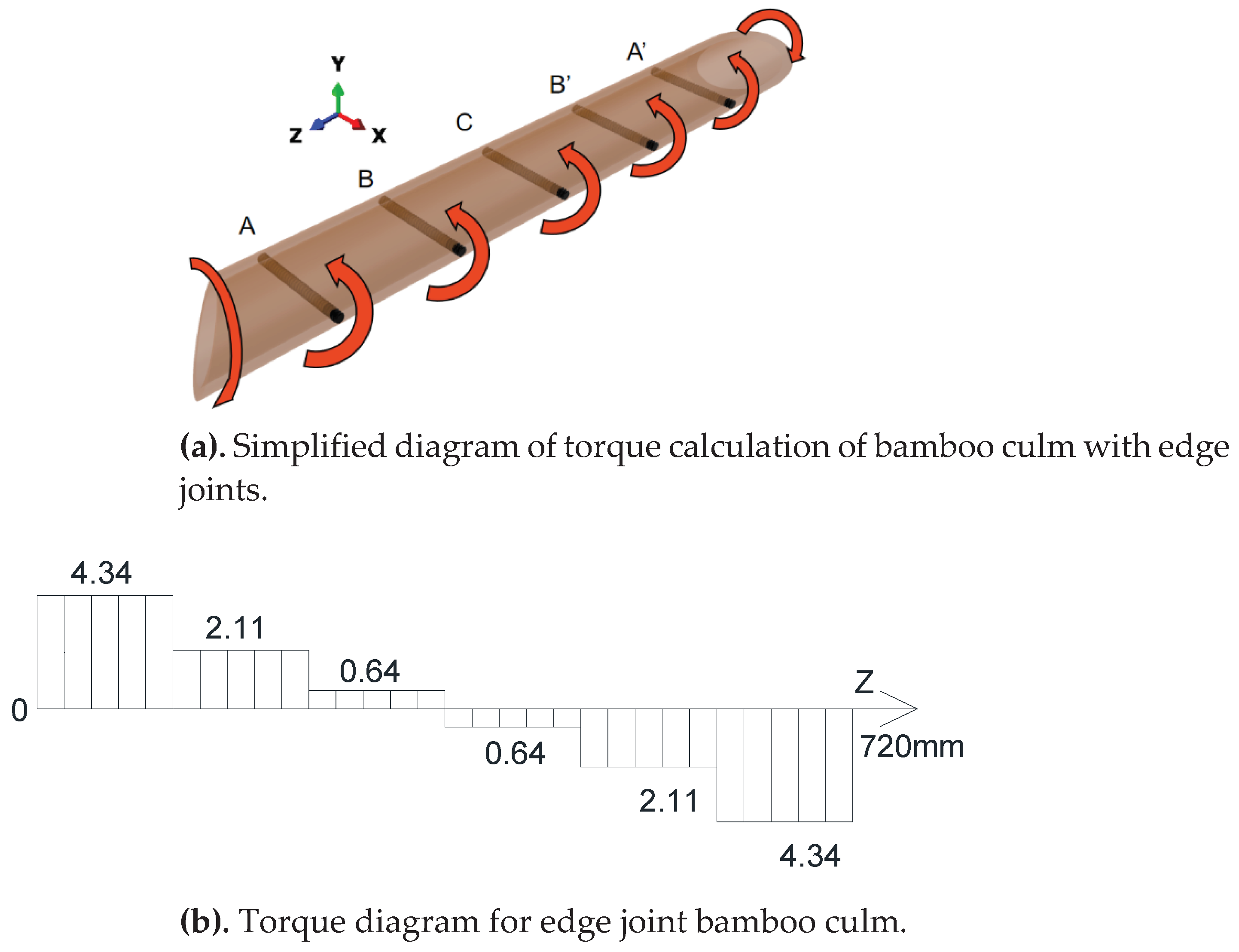
, respectively. Substituting these values into the torque calculation sketch in
Figure 15a gives the torque on each section of the bamboo culm at the edge joints (
Figure 15b).
4.2.2. Strength Calculation of Components
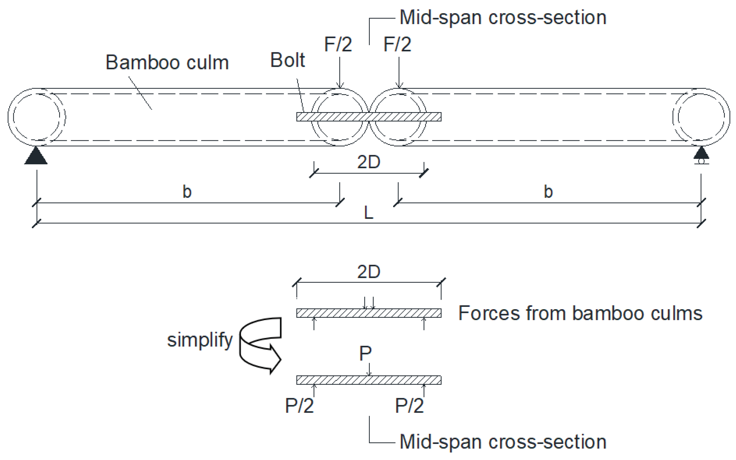
Figure 16 shows the force sketch of the bolt in bending, due to the thin wall of the bamboo pipe, the constraint of the bamboo pipe wall on the bolt can be considered as simple support, force between the outermost bolt and the walls of the bamboo tube:
Calculate the bearing compression stress at the location of the bamboo culm hole wall:
Calculate the bending strength of the outermost bolt.:
Calculate the torsional strength of the bamboo culm by taking the maximum torque of the bamboo culm:
5. Conclusions
The results of experimental and numerical simulation analyses show that the total flexural stiffness of the combined member is positively correlated with the number of bolts at the edge joint, but the efficiency of the increase decreases with the increase in the number of bolts. With the same number of bolts, it is more beneficial for the outer bolts to be close to the corner joints on that side to increase the flexural linear stiffness of the edge joint.
The calculation model of the frame-unit bamboo culm members considering the semi-rigidity of the joint is proposed, and the conversion formula between the linear stiffness of the corner and the edge joints and their rotational stiffness is deduced through the geometric relationship between the displacement and the rotation. The series and parallel relationship between corner joints and edge joints in the structure is established, and the general relationship equation between the total stiffness of the frame-unit structure and the stiffness of corner joints and edge joints is derived.
A numerical simulation method for semi-rigid joint of frame-unit bamboo culm structure is proposed. Based on the general relationship of stiffness, the corner joints are first set as completely rigid. By establishing numerical simulation, the semi-rigid rotational stiffness values, and calculation formulas of edge joints under different bolt quantity can be obtained. Then, by substituting the edge joint stiffness values obtained from numerical simulation and the total stiffness values obtained from experiments into the general relationship formula, the average semi-rigid rotational stiffness value of corner joints can be obtained. When the corner and edge joints are constructed in other forms, the method of combining test and numerical simulation proposed in this paper can also be used to obtain the corresponding rotational stiffness values and the calculation formula.
A finite element analysis method based on semi-rigid joints for frame-unit bamboo culm structure was proposed, calculated results are close to the test values, internal force sketches and calculations for bamboo culms and joints are presented, which can be used for internal force analysis and design of frame-unit prefabricated bamboo culm lattice structures.
Author Contributions
Conceptualization, Wang, G.J. and Zhuo, X.; methodology, Wang, G.J. and Zhuo, X.; software, Zhang, S.B.; validation, Wu, J. and Zhang, S.B.; experiment, Wu, J. and Zhang, S.B.; formal analysis, Wang, G.J.; resources, Wu, J. and Zhang, S.B.; data curation, Wu, J.; writing—original draft preparation, Wang, G.J.; writing—review and editing, Wang, G.J. and Zhuo, X.; supervision, Zhuo, X.; project administration, Zhuo, X.; funding acquisition, Zhuo, X. All authors have read and agreed to the published version of the manuscript.
Funding
This research was funded by the National Key Research and Development Program, Grant No. 2017YFC0703500.
Data Availability Statement
Data will be made available on request.
Conflicts of Interest
The authors declare no conflicts of interest.
References
- Lorenzo R.; Mimendi L. Digitisation of bamboo culms for structural applications. Build Eng, 2020, 29, Article 101193. [CrossRef]
- E. Zea Escamilla; G. Habert. Environmental impacts of bamboo-based construction materials representing global production diversity. Journal of Cleaner Production, 2014, 69: 117-127. [CrossRef]
- Anokye R; Bakar SE; Ratnansingam J; Awang BK. Bamboo properties and suitability as a replacement for wood. Pertanika J Sch Res Rev, 2016, 2(1): 63–79. [CrossRef]
- Chung, K.F.; Yu, W. K.; Mechanical properties of structural bamboo for bamboo scaffoldings. Eng. Struct, 2002, 24: 429-442. [CrossRef]
- Adier, M.F.V.; Sevilla, M.E.P.; Valerio, D.N.R.; Ongpeng, J.M.C. Bamboo as Sustainable Building Materials: A Systematic Review of Properties, Treatment Methods, and Standards. Buildings, 2023, 13: 2449. [CrossRef]
- Li, R. R.; He, C. J.; Peng Bo.; Wang, C. G. Differences in fiber morphology and partial physical properties in different parts of Phyllostachys edulis. Journal of Zhejiang A&F University, 2021, 38(4): 854-860. (in Chinese). [CrossRef]
- Hong, C. K.; Li, H. T.; R. Lorenzo; Wu, G.; I. Corbi; O. Corbi; Xiong, Z. H.; Yang, D.; Zhang, H. Z. Review on connections for original bamboo structures. Journal of Renewable Materials, 2019, 7(8): 713–730. [CrossRef]
- Dai, P. Q.; Luo, Z. Y.; He, M. J. Structural design and analysis for shanghai expo special project DuC. Structural Engineers, 2011, 27(4): 6―11. (in Chinese). [CrossRef]
- Huang, T.; Zhuo, X. Experimental Study on the Bending Properties of Grouting Butt Joints Reinforced by Steel Plate Embedded in Bamboo Tube. Journal of Renewable Materials, 2022, 10(4): 993–1005. [CrossRef]
- R. Moran; J.J. García. Bamboo joints with steel clamps capable of transmitting moment. Construct Build Mater, 2019, 216: 249-260. [CrossRef]
- B. Lefevre; R. West; P. O’Reilly; D. Taylor. A new method for joining bamboo culms. Eng. Struct, 2019, 190: 1-8. [CrossRef]
- Minke G. Building with Bamboo. 2012. Switzerland: Birkhäuser basel. 47-66.
- Liu, K. W.; Xu, Q. F.; Wang, G.; Chen, F. M.; Leng, Y. B.; Yang, J.; K. A. Harries. Contemporary Bamboo Architecture in China. 2022. Beijing:TsingHua University press. 31-55.
- Zhuo, X.; Dong, S. L. Bamboo tube bundle spatial lattice structure system and construction technology. Spatial Structure, 2021, 27(1): 3–8. (in Chinese). [CrossRef]
- Zhuo, X.; Dong, S. L. Frame-unit prefabricated bamboo culm lattice structure system and engineering practices. Journal of building structures, 2024, 45(3): 43-51. (in Chinese). [CrossRef]
- Zhu, C. M.; Zhang, W. P. Structural Mechanics (volume 2). 2016. Beijing: Higher Education Press. 51-54. (in Chinese).
- J. García, C. Rangel, K. Ghavami. Experiments with rings to determine the anisotropic elastic constants of bamboo. Constr. Build. Mater. 2010. 31: 52-57. [CrossRef]
- Zhang, X. X.; Yu, Z. X.; Yu, Y.; Wang, H. K.; Li, J. H. Axial compressive behavior of Moso Bamboo and its components with respect to fiber-reinforced composite structure, J. For. Res. 2019. 30(6): 2371–2377. [CrossRef]
- Walter Liese; Michael Köhl. Bamboo The Plant and its Use. 2015. Switzerland: Springer International Publishing. 251-253.
- Peng, H., Zhuo, X. Research on Mechanical Behavior of the Screwed Connection at the End of Bamboo Strip. Zhejiang University, Hangzhou, Zhejiang Province. 2022. (in Chinese). [CrossRef]
Figure 1.
Structural forming principles and two types of joints.
Figure 1.
Structural forming principles and two types of joints.
Figure 2.
Corner joint and Edge joint.
Figure 2.
Corner joint and Edge joint.
Figure 3.
Loading device.
Figure 3.
Loading device.
Figure 4.
Dimensions of specimens (unit: mm).
Figure 4.
Dimensions of specimens (unit: mm).
Figure 5.
Deformation of test specimen joints after loading.
Figure 5.
Deformation of test specimen joints after loading.
Figure 6.
Experimental data and fitted values.
Figure 6.
Experimental data and fitted values.
Figure 7.
Schematic diagram for structural deformation calculation.
Figure 7.
Schematic diagram for structural deformation calculation.
Figure 8.
Series and parallel relationships between the joints.
Figure 8.
Series and parallel relationships between the joints.
Figure 9.
Loading surface and boundary conditions.
Figure 9.
Loading surface and boundary conditions.
Figure 10.
Semi-rigid corner joints.
Figure 10.
Semi-rigid corner joints.
Figure 11.
Comparison of theoretical and numerical values.
Figure 11.
Comparison of theoretical and numerical values.
Figure 12.
Side distance s.
Figure 12.
Side distance s.
Figure 13.
K-s relationship for different number of bolts.
Figure 13.
K-s relationship for different number of bolts.
Figure 14.
Equivalent solid model to beam model.
Figure 14.
Equivalent solid model to beam model.
Figure 15.
Torque calculation of edge joint bamboo culm.
Figure 15.
Torque calculation of edge joint bamboo culm.
Figure 16.
Bolt calculation diagram.
Figure 16.
Bolt calculation diagram.
Table 1.
Test variable.
| Specimens number |
S2test |
S3test |
S5test |
| Bolt positions |
A, A’ |
A, C, A’ |
A, B, C, B’, A’ |
| Maximum load applied (N) |
620.3 |
620.3 |
620.3 |
Table 2.
Properties of bamboo materials.
Table 2.
Properties of bamboo materials.
| E1 |
E2 |
E3 |
V23 |
V13 |
V12 |
G23 |
G13 |
G12 |
| 398 |
14700 |
398 |
0.3 |
0.14 |
0.008 |
581 |
175 |
581 |
Table 3.
Bending moment ratio of each bolt.
Table 3.
Bending moment ratio of each bolt.
| Bolt position |
n=2 |
n=3 |
n=5 |
| A |
0.5 |
0.366 |
0.258 |
| B |
/ |
/ |
0.169 |
| C |
/ |
0.268 |
0.146 |
Table 4.
Linear stiffness values of edge joints obtained by numerical simulation.
Table 4.
Linear stiffness values of edge joints obtained by numerical simulation.
| n |
2 |
3 |
5 |
|
51.8 |
66.0 |
84.3 |
|
22.6 |
28.6 |
33.9 |
Table 5.
Linear stiffness values of edge joints obtained by numerical simulation.
Table 5.
Linear stiffness values of edge joints obtained by numerical simulation.
| n=2 |
n=3 |
n=5 |
|
|
|
|
|
|
|
|
|
| 100 |
15.6 |
15.8 |
100 |
16.7 |
16.9 |
100 |
17.7 |
17.9 |
| 200 |
24.0 |
24.2 |
200 |
26.7 |
26.9 |
200 |
29.3 |
29.5 |
| 300 |
29.3 |
29.4 |
300 |
33.4 |
33.5 |
300 |
37.5 |
37.6 |
| 400 |
32.9 |
33.0 |
400 |
38.1 |
38.2 |
400 |
43.5 |
43.7 |
Table 6.
Linear stiffness values of edge joints obtained by numerical simulation.
Table 6.
Linear stiffness values of edge joints obtained by numerical simulation.
| n |
2 |
3 |
5 |
|
176.8 |
222.6 |
250.1 |
Table 7.
Linear stiffness values of edge joints obtained by numerical simulation.
Table 7.
Linear stiffness values of edge joints obtained by numerical simulation.
| n |
2 |
3 |
5 |
|
90 |
180 |
270 |
90 |
180 |
270 |
90 |
180 |
270 |
|
51.8 |
42.4 |
36.3 |
66.0 |
54.0 |
45.3 |
84.3 |
67.8 |
56.0 |
|
Disclaimer/Publisher’s Note: The statements, opinions and data contained in all publications are solely those of the individual author(s) and contributor(s) and not of MDPI and/or the editor(s). MDPI and/or the editor(s) disclaim responsibility for any injury to people or property resulting from any ideas, methods, instructions or products referred to in the content. |
© 2024 by the authors. Licensee MDPI, Basel, Switzerland. This article is an open access article distributed under the terms and conditions of the Creative Commons Attribution (CC BY) license (http://creativecommons.org/licenses/by/4.0/).
