Submitted:
06 March 2024
Posted:
08 March 2024
You are already at the latest version
Abstract
Keywords:
1. Introduction
2. Mathematical Model
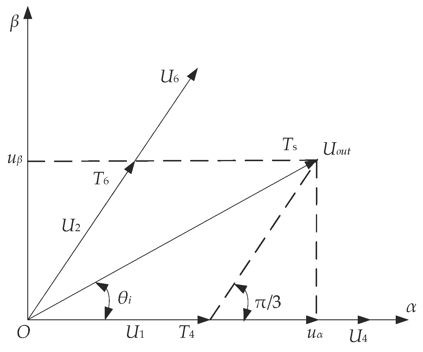
2.1. SVPWM Technology
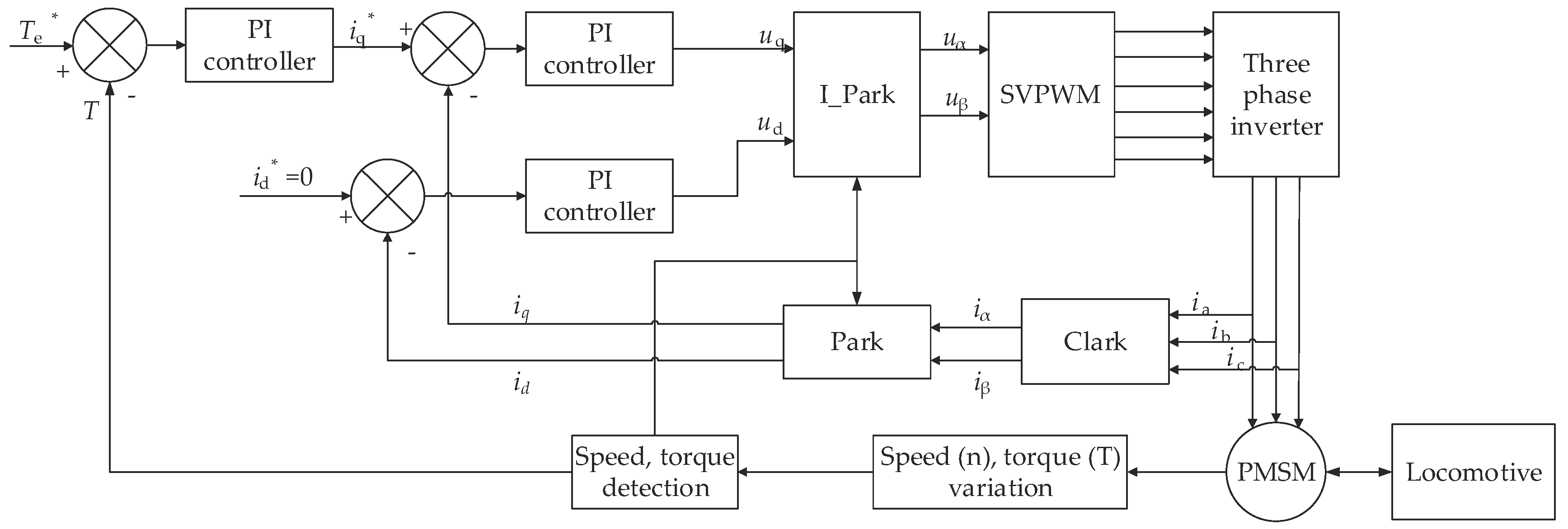
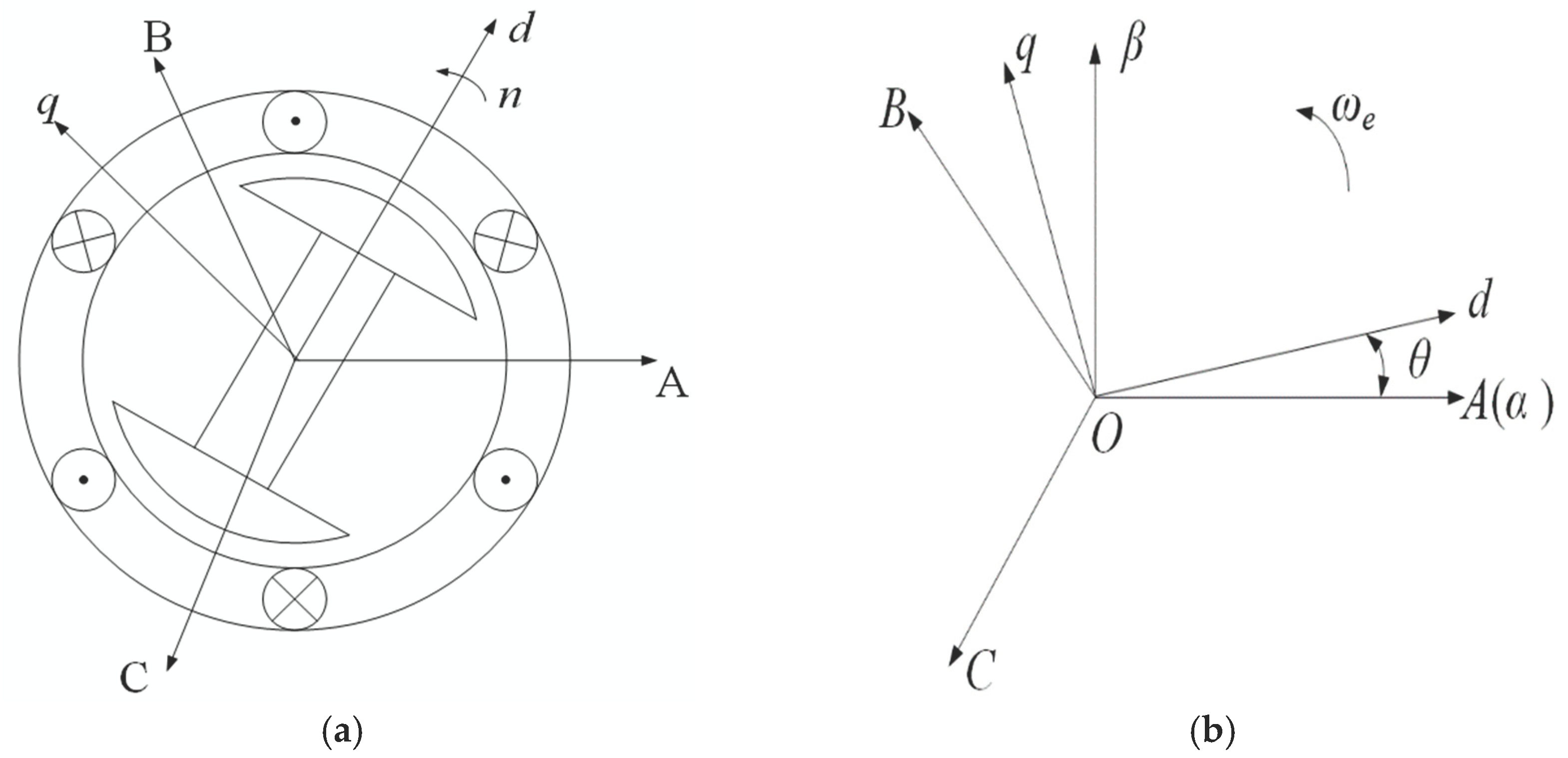
2.2. Vector Control of PMSM
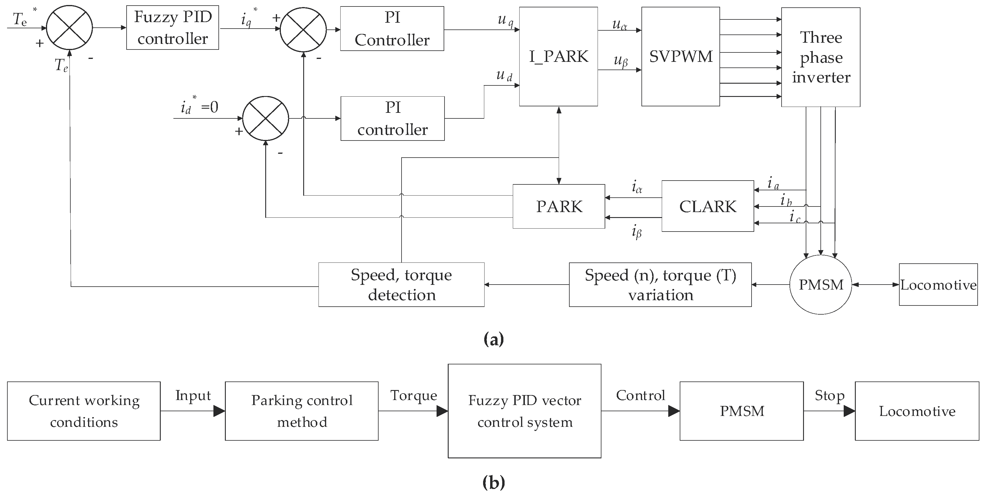
2.3. F-PID Vector Control of PMSM
| ec | e | ||||||
|---|---|---|---|---|---|---|---|
| NB | NM | NS | ZO | PS | PM | PB | |
| NB | PB | PB | PM | PM | PS | PS | ZO |
| NM | PB | PB | PM | PM | PS | ZO | ZO |
| NS | PM | PM | PM | PS | ZO | NS | NM |
| ZO | PM | PS | PS | ZO | NS | NM | NM |
| PS | PS | PS | ZO | NS | NS | NM | NM |
| PM | ZO | ZO | NS | NM | NM | NM | NB |
| PB | ZO | NS | NS | NM | NM | NB | NB |
| ec | e | ||||||
|---|---|---|---|---|---|---|---|
| NB | NM | NS | ZO | PS | PM | PB | |
| NB | NB | NM | NM | NS | ZO | ZO | ZO |
| NM | NB | NM | NM | NS | ZO | ZO | ZO |
| NS | NM | NM | NS | ZO | ZO | PS | PS |
| ZO | NM | NS | NS | ZO | PS | PS | PS |
| PS | NM | NS | ZO | PS | PS | PM | PM |
| PM | NS | ZO | ZO | NS | PS | PM | PB |
| PB | ZO | ZO | PS | PS | PS | PB | PB |
| ec | e | ||||||
|---|---|---|---|---|---|---|---|
| NB | NM | NS | ZO | PS | PM | PB | |
| NB | PS | PS | ZO | ZO | ZO | PM | PB |
| NM | NS | NM | NM | NS | PM | PM | PM |
| NS | NB | NM | NM | NS | PM | PS | PM |
| ZO | NM | NM | NM | NS | PS | PS | PM |
| PS | NB | NB | NS | NS | PS | PS | PM |
| PM | NM | NB | NS | NS | ZO | PM | PB |
| PB | PS | ZO | ZO | ZO | ZO | PB | PB |
2.4. F-PID Vector Controller in Parking System
3. Simulation and Experiment
3.1. Simulation
3.1.1. F-PID Control: Simulation for Electric Locomotives
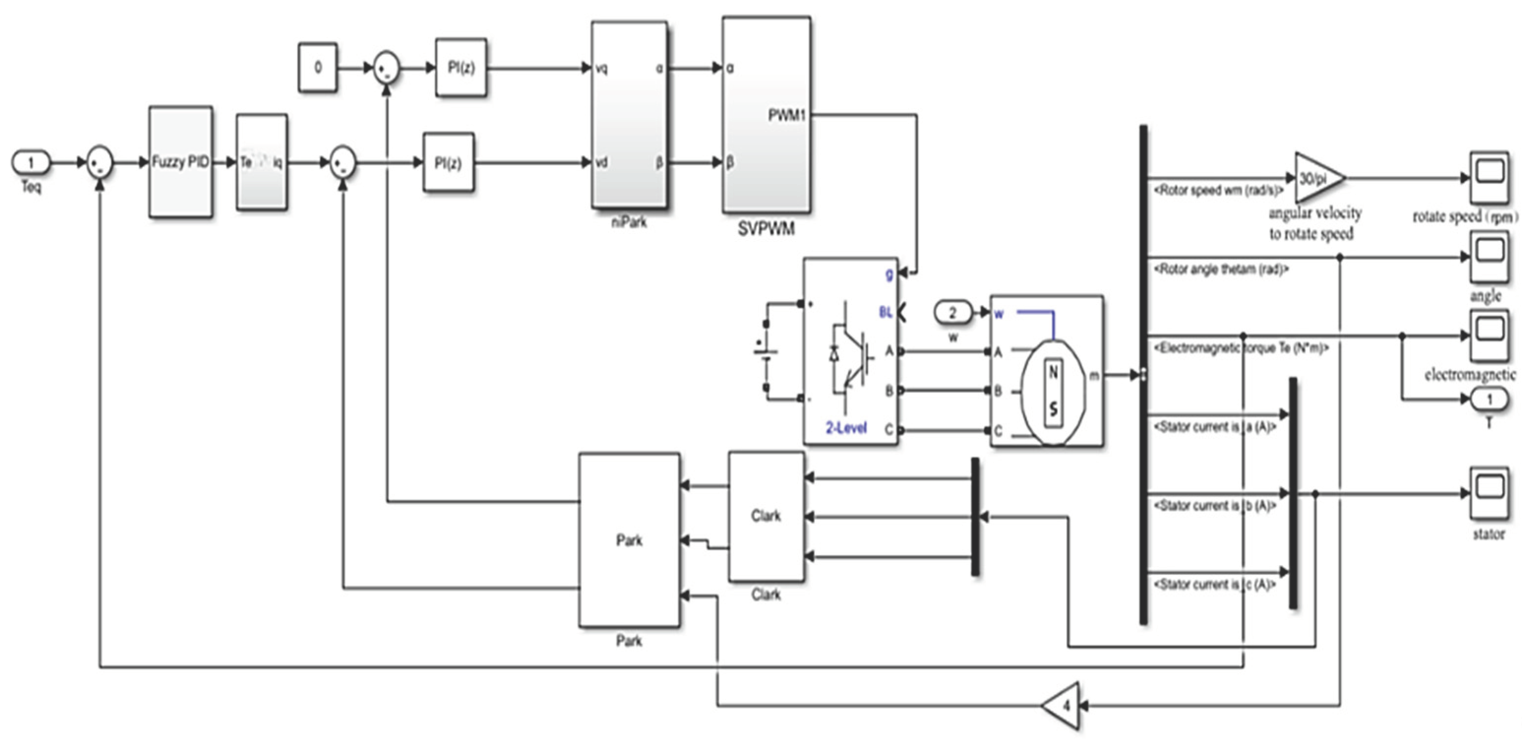
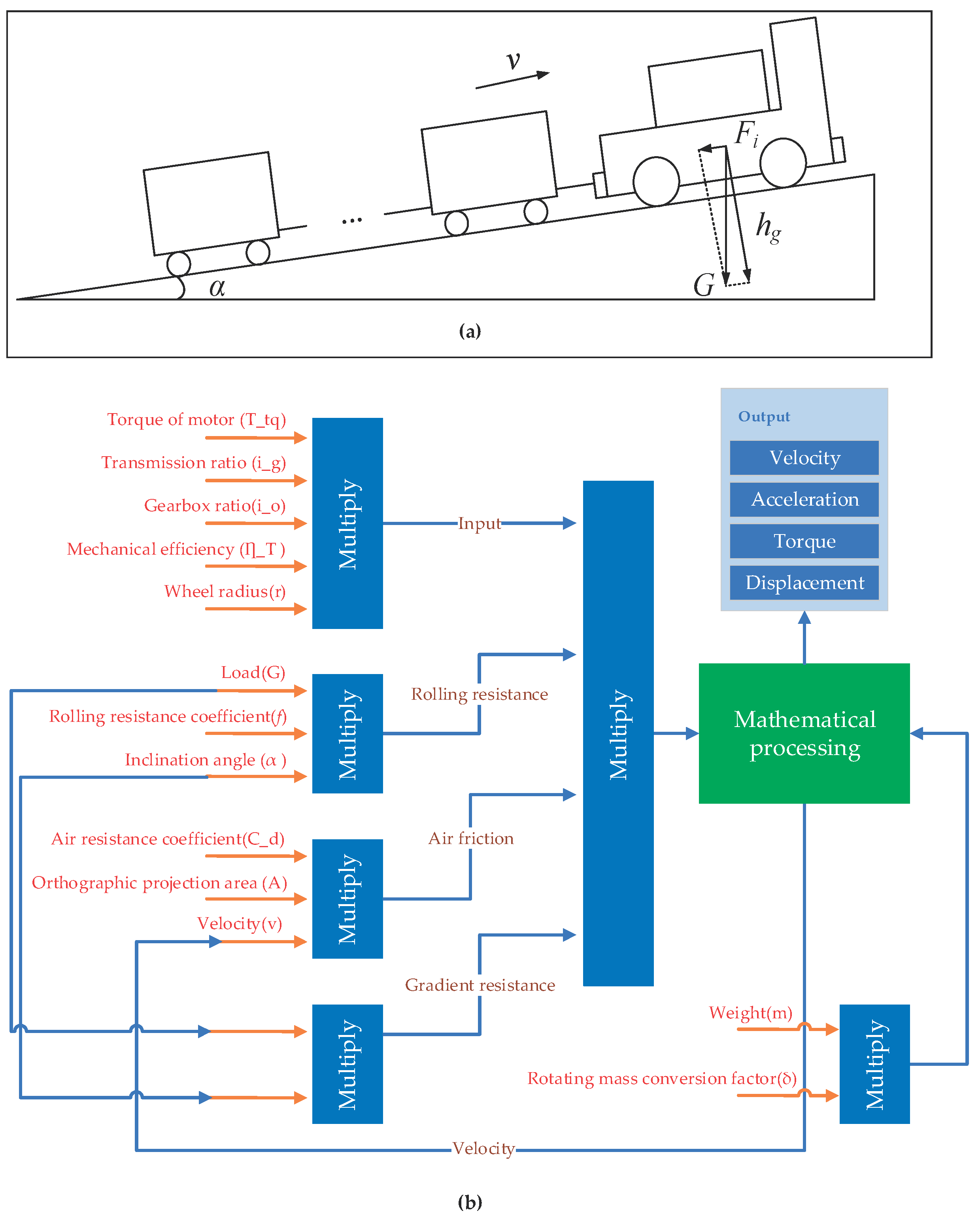
3.1.2. Modeling Electric Locomotive Dynamics with Simulink
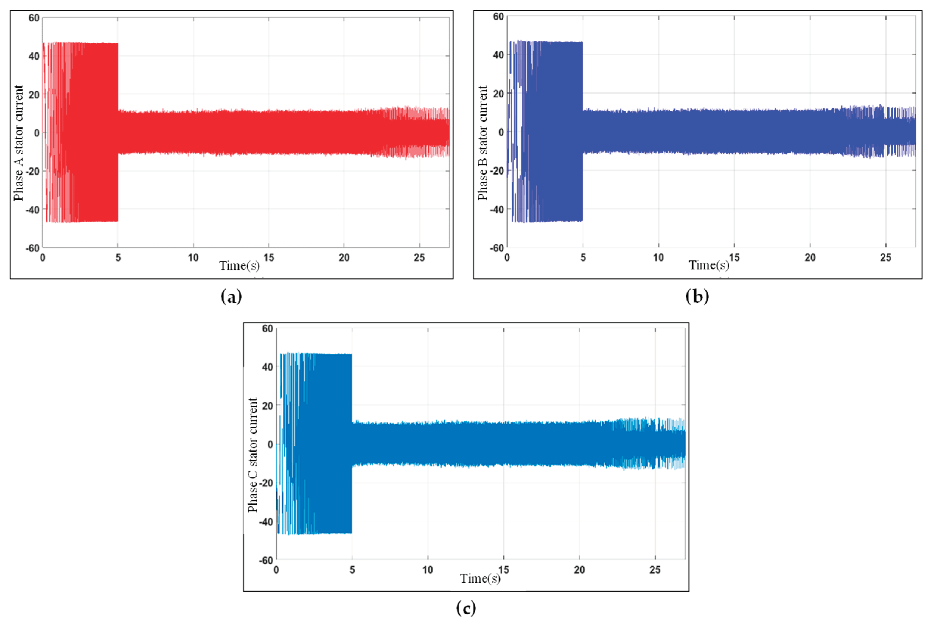
3.1.3. Validation of Three-Phase Stator Current Control
- The three stator currents are sinusoidal and well-balanced, indicating that the PMSM is operating properly.
- The current amplitude is relatively low, which is desirable for efficiency reasons.
- The stator current is well-regulated, even under demanding operating conditions.
3.1.4. Electromagnetic Torque in Locomotive Stopping
3.1.5. Analyzing Stopping Control Error under Diverse Working Conditions
3.2. Experiment
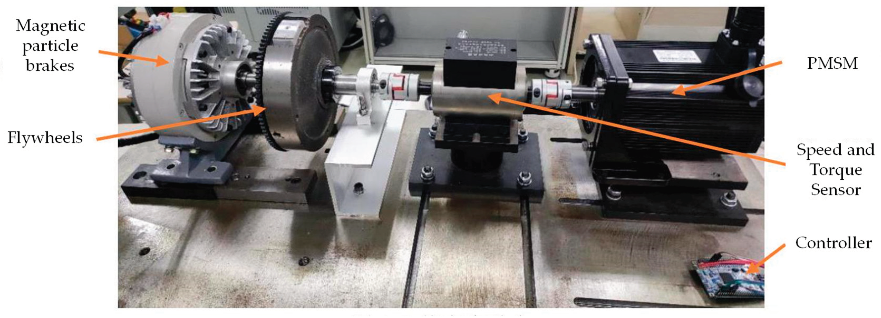
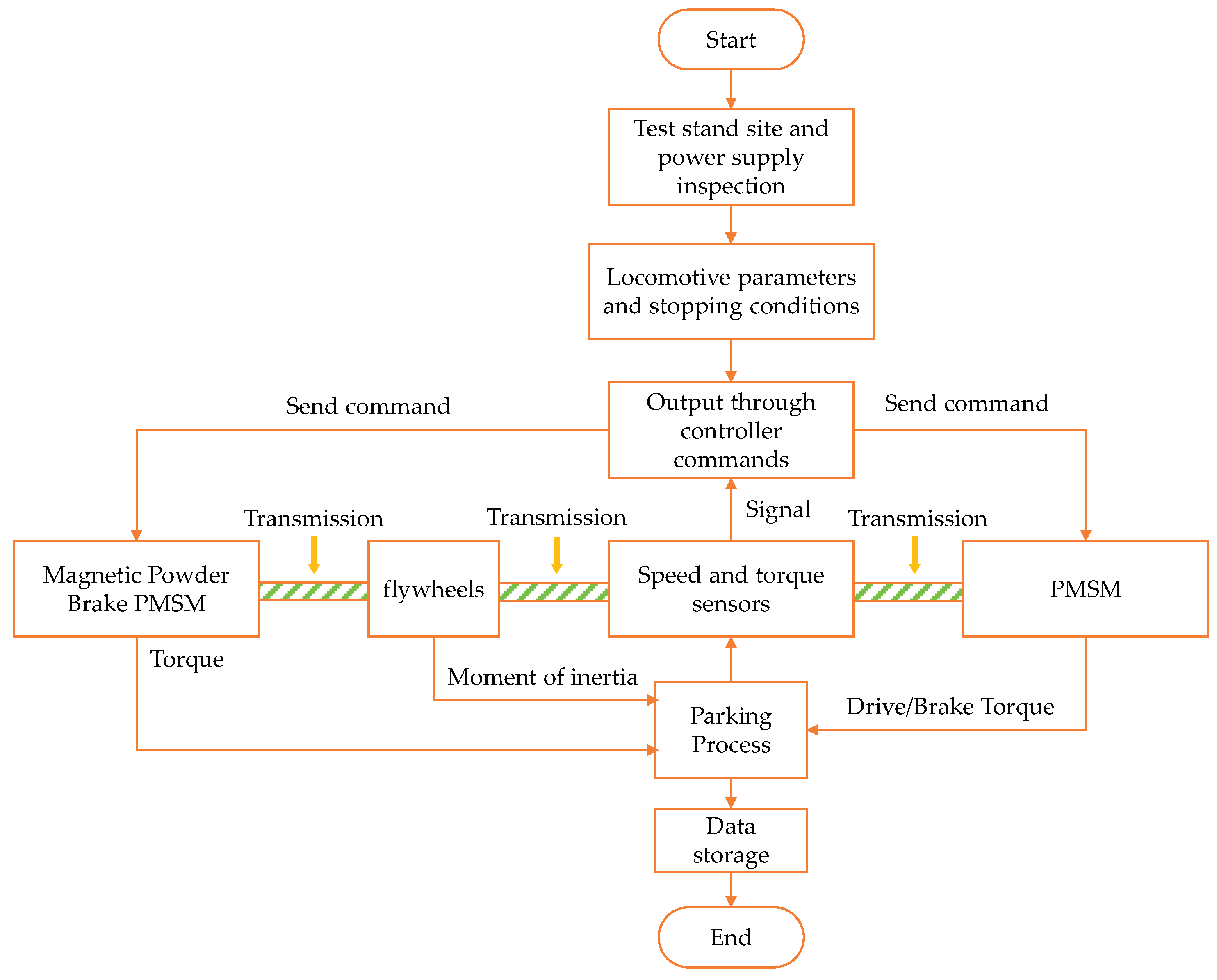
3.2.1. Principle and Selection of Test Bench
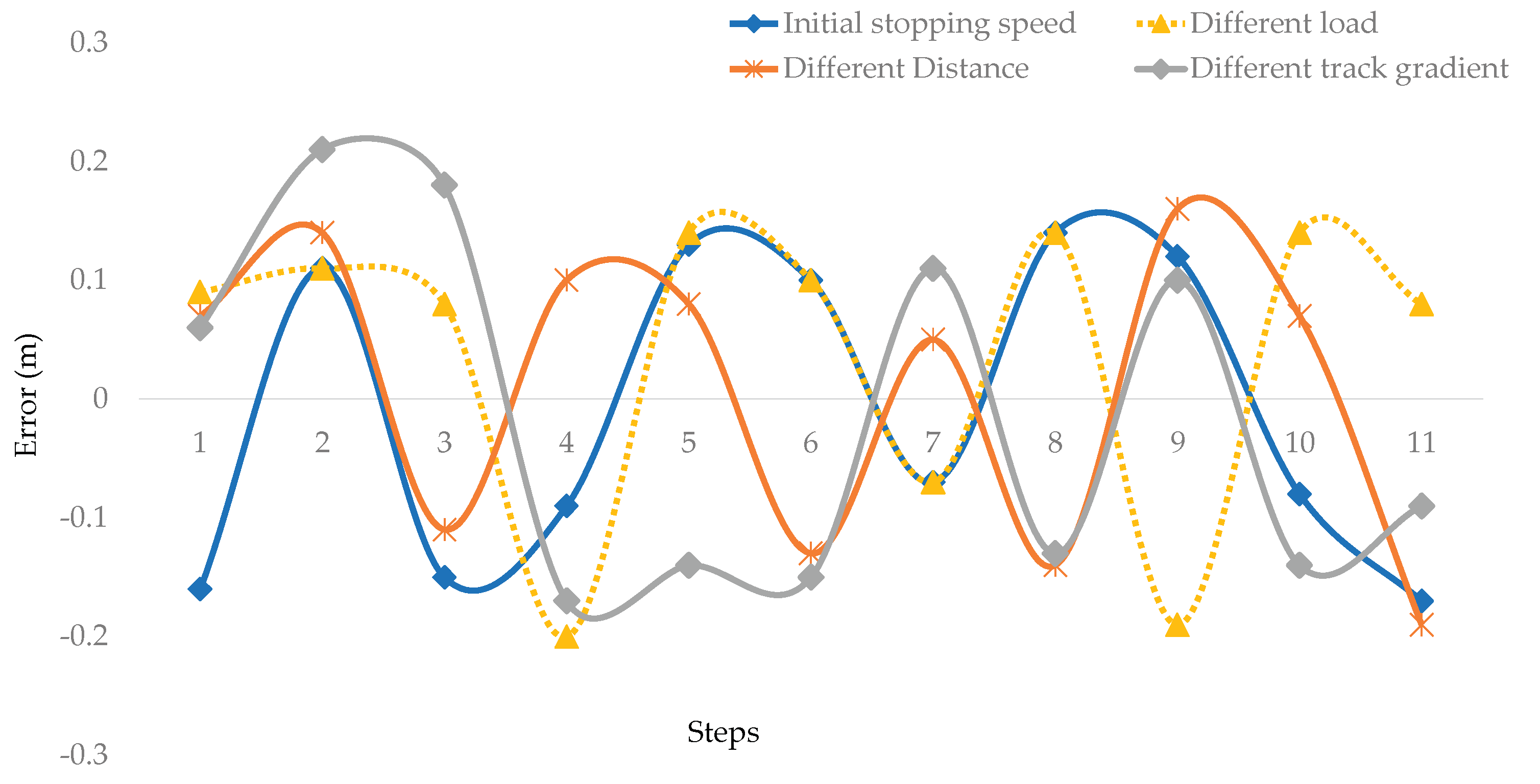
3.2.2. Comparative Result Analysis
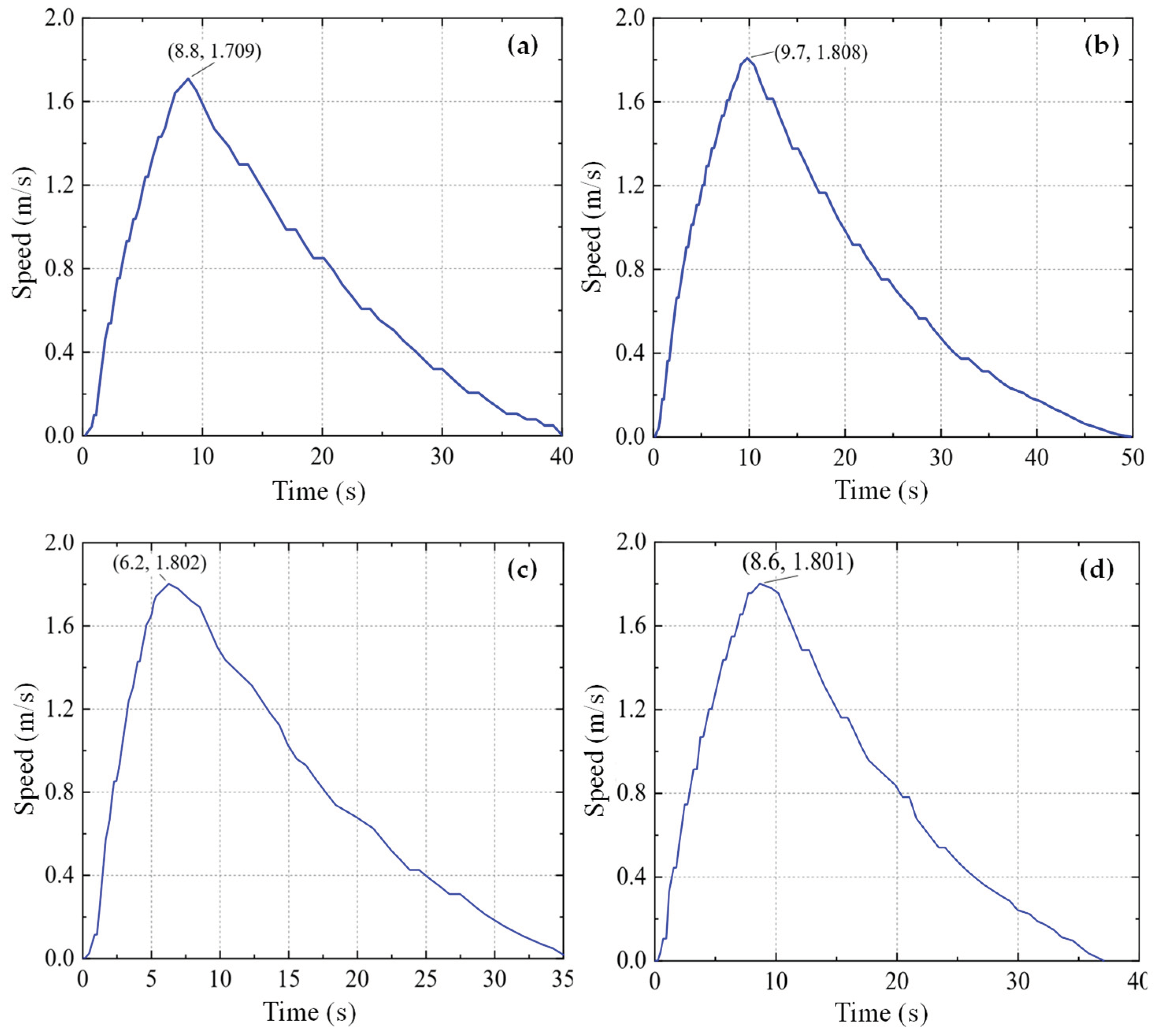
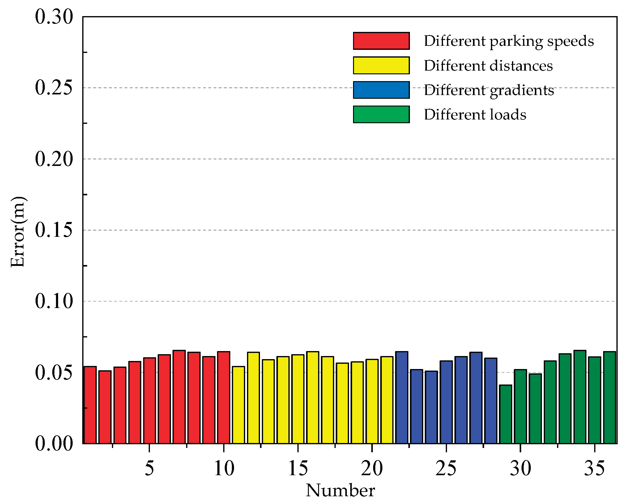
3.2.3. Error and Validation
4. Conclusion
Author Contributions
Funding
Data Availability Statement
Acknowledgments
Conflicts of Interest
References
- Fan, G.W.J.Z. Design and practice of integrated system for intelligent unmanned working face mining system in Huangling coal mine. Coal Eng. 2016, 48, 84–87. [Google Scholar] [CrossRef]
- Wang, G.; Ren, H.; Zhao, G.; Zhang, D.; Wen, Z.; Meng, L.; Gong, S. Research and practice of intelligent coal mine technology systems in China. Int. J. Coal Sci. Technol. 2022, 9, 24. [Google Scholar] [CrossRef]
- Wang, M.; Bao, J.; Yuan, X.; Yin, Y.; Khalid, S. Research Status and Development Trend of Unmanned Driving Technology in Coal Mine Transportation. Energies 2022, 15, 9133. [Google Scholar] [CrossRef]
- Libing, Z.; Libing, Z. Research on unmanned driving system of underground trackless rubber-tyred vehicle in coal mine. J. Mine Autom. 2022, 48, 36–48. [Google Scholar] [CrossRef]
- Wang, G.; Yan, X.; Kou, Z.; Deng, H.; Wang, K. Research on Operation Conflict of Auxiliary Transport Locomotive in Complex Mine Based on Extended Petri Net. Machines 2023, 11, 552. [Google Scholar] [CrossRef]
- Alanazi, F. Electric Vehicles: Benefits, Challenges, and Potential Solutions for Widespread Adaptation. Appl. Sci. 2023, 13, 6016. [Google Scholar] [CrossRef]
- Kummerle, R.; Hahnel, D.; Dolgov, D.; Thrun, S.; Burgard, W. Autonomous driving in a multi-level parking structure. In Proceedings of the 2009 IEEE International Conference on Robotics and Automation; 2009; pp. 3395–3400. [Google Scholar] [CrossRef]
- Pendleton, S.; Andersen, H.; Du, X.; Shen, X.; Meghjani, M.; Eng, Y.; Rus, D.; Ang, M. Perception, Planning, Control, and Coordination for Autonomous Vehicles. Machines 2017, 5, 6. [Google Scholar] [CrossRef]
- Gao, M. The application and prospect of electrification in transportation. Appl. Comput. Eng. 2023, 26, 73–78. [Google Scholar] [CrossRef]
- Ohama, Y.; Tanaka, K.; Yasuda, H.; Obata, K.; Fukumura, N. Improvements in Perpendicular Reverse Parking by Directing Drivers’ Preliminary Behavior. IEEE Access 2021, 9, 92003–92016. [Google Scholar] [CrossRef]
- Han, I. Geometric Path Plans for Perpendicular/Parallel Reverse Parking in a Narrow Parking Spot with Surrounding Space. Vehicles 2022, 4, 1195–1208. [Google Scholar] [CrossRef]
- Wang, Y.; De Schutter, B.; van den Boom, T.J.J.; Ning, B.; Tang, T. Efficient Bilevel Approach for Urban Rail Transit Operation With Stop-Skipping. IEEE Trans. Intell. Transp. Syst. 2014, 15, 2658–2670. [Google Scholar] [CrossRef]
- Wang, C.; Tu, S.; Zhang, L.; Yang, Q.; Tu, H. Auxiliary transportation mode in a fully-mechanized face in a nearly horizontal thin coal seam. Int. J. Min. Sci. Technol. 2015, 25, 963–968. [Google Scholar] [CrossRef]
- Votava, J.; Kyncl, J.; Straka, L. Energy consumption measurements based on numerical integration. In Proceedings of the 2018 19th International Scientific Conference on Electric Power Engineering (EPE); 2018; pp. 1–4. [Google Scholar] [CrossRef]
- Liu, R.; Golovitcher, I.M. Energy-efficient operation of rail vehicles. Transp. Res. Part A Policy Pract. 2003, 37, 917–932. [Google Scholar] [CrossRef]
- Sicre, C.; Cucala, A.P.; Fernández, A.; Lukaszewicz, P. Modeling and optimizing energy-efficient manual driving on high-speed lines. IEEJ Trans. Electr. Electron. Eng. 2012, 7, 633–640. [Google Scholar] [CrossRef]
- Bai, Y.; Ho, T.K.; Mao, B.; Ding, Y.; Chen, S. Energy-Efficient Locomotive Operation for Chinese Mainline Railways by Fuzzy Predictive Control. IEEE Trans. Intell. Transp. Syst. 2014, 15, 938–948. [Google Scholar] [CrossRef]
- Lv, Y.; Wang, H.H.; Wang, X.J.; Tao, X.H.; Yang, J.X. Research of the Precision Positioning Method for Electric Locomotive Automatic Control System. Appl. Mech. Mater. 2013, 389, 507–512. [Google Scholar] [CrossRef]
- Shi, J.; Li, K.; Piao, C.; Gao, J.; Chen, L. Model-Based Predictive Control and Reinforcement Learning for Planning Vehicle-Parking Trajectories for Vertical Parking Spaces. Sensors 2023, 23, 7124. [Google Scholar] [CrossRef] [PubMed]
- Xu, X.; Li, L.; Jiao, W.; Zhang, Q. Challenges of Autonomous Navigation and Perception Technology for Unmanned Special Vehicles in Underground Mine. In Proceedings of the 2023 6th International Symposium on Autonomous Systems (ISAS); 2023; pp. 1–6. [Google Scholar] [CrossRef]
- Chen, Q.; Huang, J.; Xiao, Q. Design of Monitoring System for Brake Shoe of Electric Locomotive. Procedia Comput. Sci. 2022, 208, 73–78. [Google Scholar] [CrossRef]
- Ke, Q.; Zhang, Y. Research on Automatic Operation Control Algorithm of High Speed Train Based on Artificial Neural Network. IOP Conf. Ser. Mater. Sci. Eng. 2019, 677, 042046. [Google Scholar] [CrossRef]
- Shen, Q.; Sun, N.; Zhao, G.; Han, X.; Tang, R. Design of a Permanent Magnet Synchronous Motor and Performance Analysis for Subway. In Proceedings of the 2010 Asia-Pacific Power and Energy Engineering Conference; 2010; pp. 1–4. [Google Scholar] [CrossRef]
- Pillay, P.; Krishnan, R. Modeling, simulation, and analysis of permanent-magnet motor drives. I. The permanent-magnet synchronous motor drive. IEEE Trans. Ind. Appl. 1989, 25, 265–273. [Google Scholar] [CrossRef]
- Shamrooz Aslam, M.; Tiwari, P.; Pandey, H.M.; Band, S.S.; El Sayed, H. A delayed Takagi–Sugeno fuzzy control approach with uncertain measurements using an extended sliding mode observer. Inf. Sci. 2023, 643, 119204. [Google Scholar] [CrossRef]
- Aslam, M.S.; Bilal, H.; Hayajneh, M. Lqr-based PID controller with variable load tuned with data-driven methods for double inverted pendulum. Soft Comput. 2024, 28, 325–338. [Google Scholar] [CrossRef]
- Mi, Y.; Song, Y.; Fu, Y.; Wang, C. The Adaptive Sliding Mode Reactive Power Control Strategy for Wind–Diesel Power System Based on Sliding Mode Observer. IEEE Trans. Sustain. Energy 2020, 11, 2241–2251. [Google Scholar] [CrossRef]
- Karboua, D.; Belgacem, T.; Khan, Z.H.; Kellal, C. Robust performance comparison of PMSM for flight control applications in more electric aircraft. PLoS ONE 2023, 18, e0283541. [Google Scholar] [CrossRef] [PubMed]
- Eltag, K.; Aslamx, M.S.; Ullah, R. Dynamic Stability Enhancement Using Fuzzy PID Control Technology for Power System. Int. J. Control Autom. Syst. 2019, 17, 234–242. [Google Scholar] [CrossRef]
- Xiao-jing, S. Design and Simulation of PMSM Feedback Linearization Control System. TELKOMNIKA Indones. J. Electr. Eng. 2013, 11. [Google Scholar] [CrossRef]
- Karabacak, M.; Eskikurt, H.I. Design, modelling and simulation of a new nonlinear and full adaptive backstepping speed tracking controller for uncertain PMSM. Appl. Math. Model. 2012, 36, 5199–5213. [Google Scholar] [CrossRef]
- Liu, X.; Zhang, G.; Mei, L.; Wang, D. Backstepping control with speed estimation of PMSM based on MRAS. Autom. Control Comput. Sci. 2016, 50, 116–123. [Google Scholar] [CrossRef]


| Parameter | Symbol | Value |
|---|---|---|
| Transmission ratio | 1 | |
| Main Reducer Ratio | 13 | |
| Driveline mechanical efficiency | 0.92 | |
| Wheel radius (m) | 0.23 | |
| Rolling resistance coefficient | f | 0.008 |
| Atmospheric drag coefficient | 0.6 | |
| Vehicle projected area (m2) | 2.2275 | |
| Rotating mass conversion factor | 1.085 |
| Different condition | Stopping speed | Set distance | Slope | Load |
|---|---|---|---|---|
| (m/s) | (m) | (degree) | (kg) | |
| Initial stopping speed | 0.9-1.8 | 20 | 0 | 12000 |
| Different Distance | 1.8 | 15-20 | 0 | 12000 |
| Different track gradient | 1.8 | 20 | 0-5 | 12000 |
| Different load | 1.8 | 20 | 0 | 10000-12000 |
| Initial stopping speed | Different distance | Different track gradient | Different load | |
|---|---|---|---|---|
| Maximum | 0.140 | 0.160 | 0.210 | 0.140 |
| Minimum | -0.170 | -0.190 | -0.170 | -0.200 |
| Mean | -0.011 | 0.009 | -0.015 | 0.038 |
| Standard deviation | 0.130 | 0.126 | 0.147 | 0.129 |
Disclaimer/Publisher’s Note: The statements, opinions and data contained in all publications are solely those of the individual author(s) and contributor(s) and not of MDPI and/or the editor(s). MDPI and/or the editor(s) disclaim responsibility for any injury to people or property resulting from any ideas, methods, instructions or products referred to in the content. |
© 2024 by the authors. Licensee MDPI, Basel, Switzerland. This article is an open access article distributed under the terms and conditions of the Creative Commons Attribution (CC BY) license (http://creativecommons.org/licenses/by/4.0/).


