Submitted:
07 March 2024
Posted:
08 March 2024
You are already at the latest version
Abstract
Keywords:
1. Introduction
2. Bearing Specification
3. Rotational Speed
4. Oil Lubrication
4. Numerical Approach
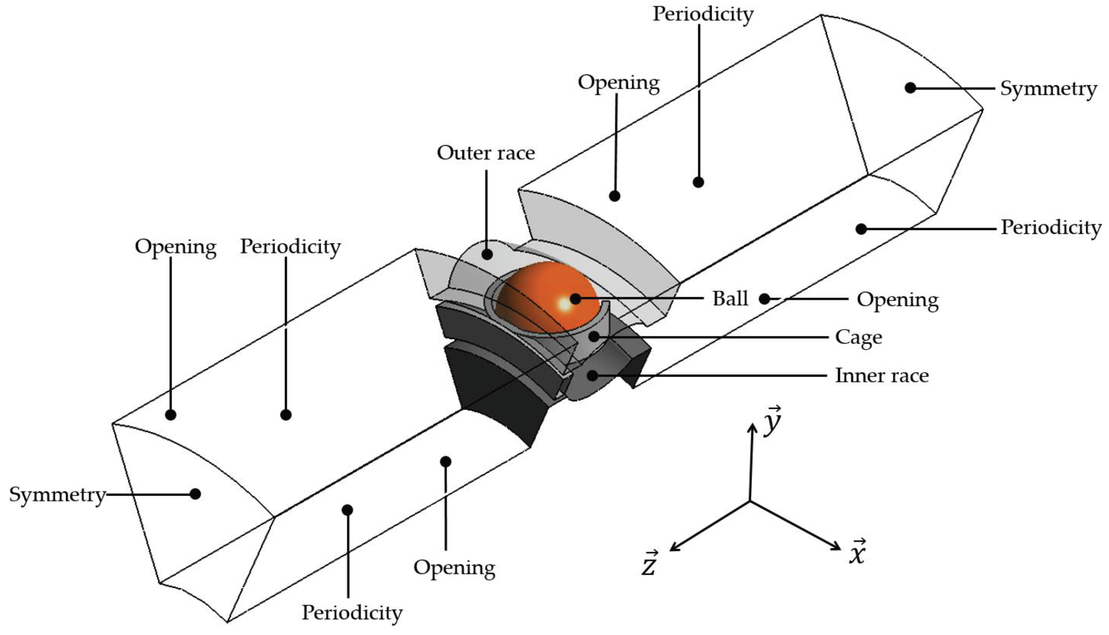
4.1. Numerical Domain
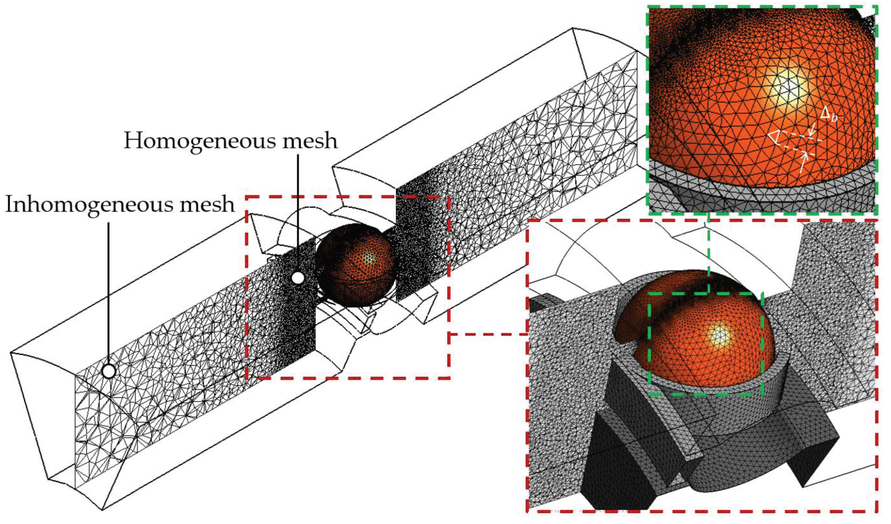
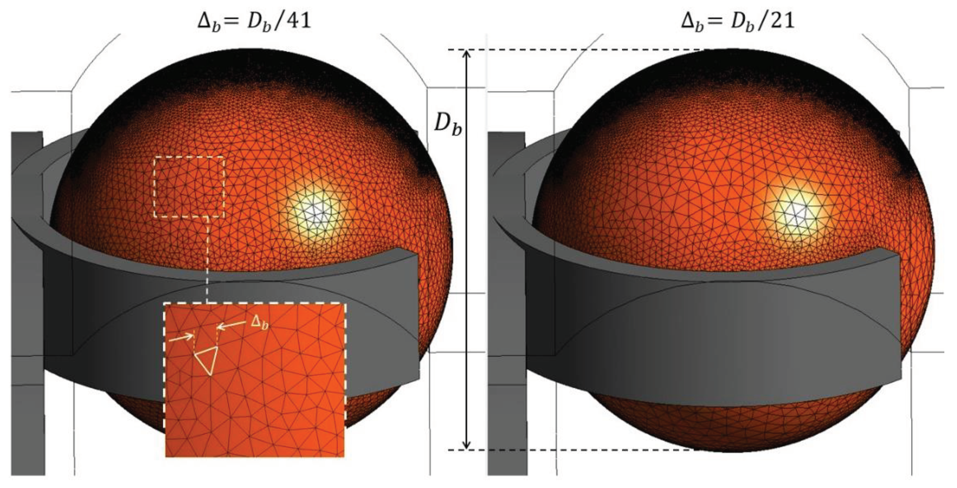
4.2. Mesh
4.3. Boundary Conditions
4.4. Governing Equations
4.5. Time Discretization
4.6. Convergence Criteria
5. Setting Up the Numerical Approach
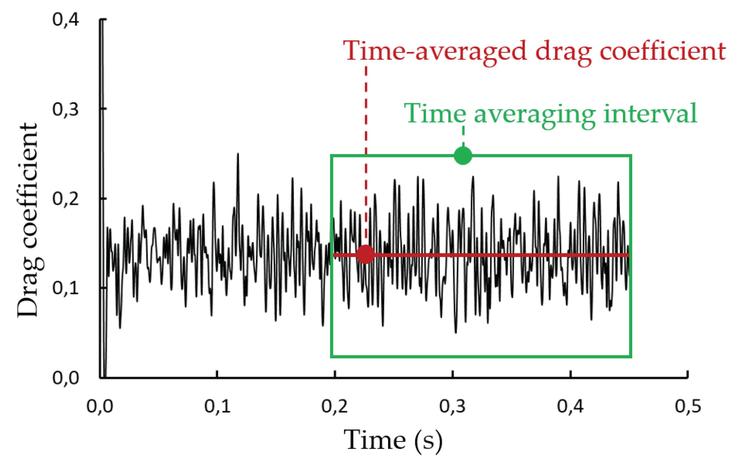
5.1. Time Evolution of the Drag Coefficient, Streamlines and Pressure Distribution
5.2. Influence of the Mesh
| (mm) | Relative size of the cell | |
| 0.5 | − | |
| 1.0 | 0.98 | |
| 2.0 | 0.91 |
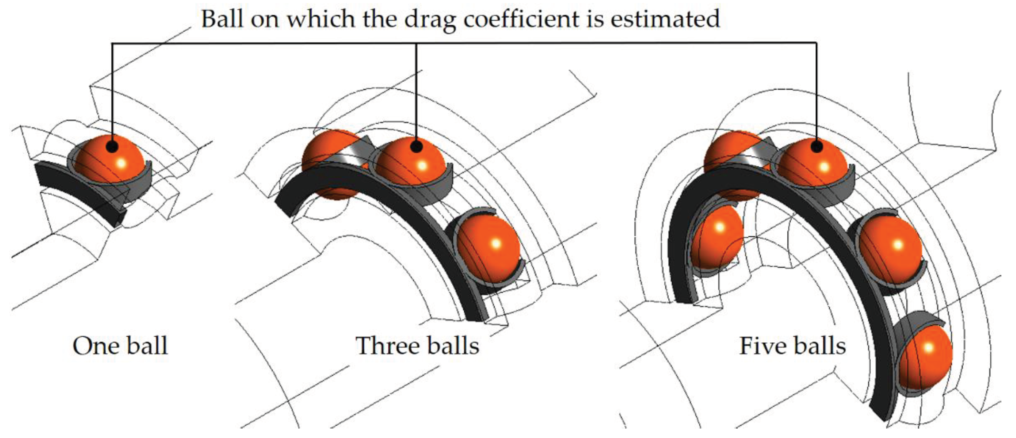
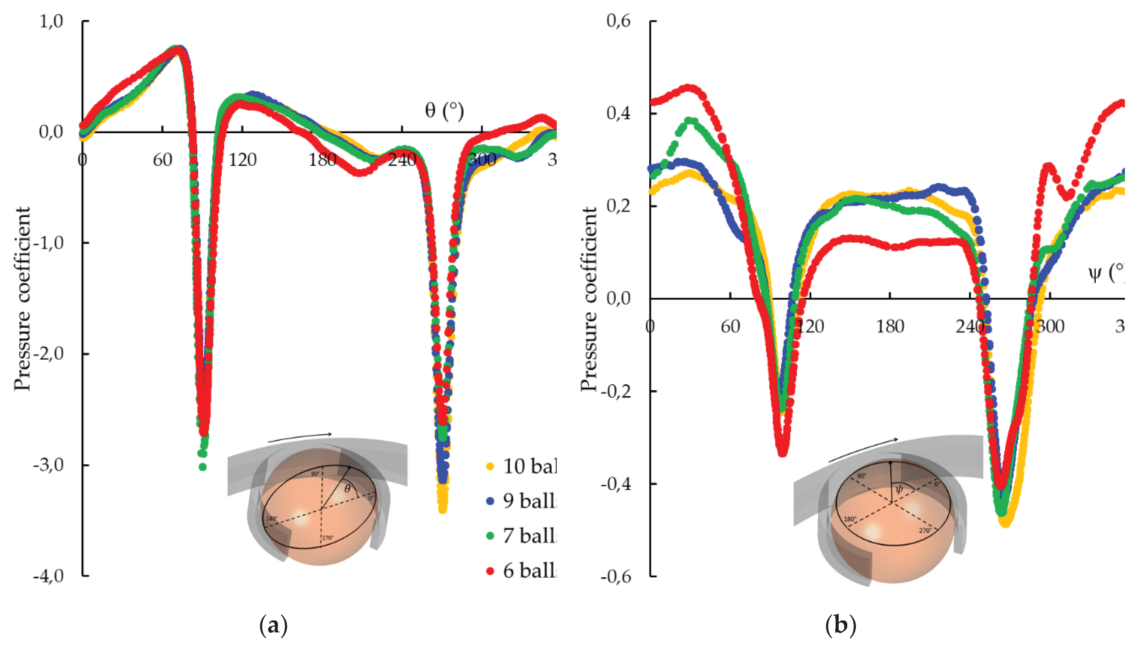
5.3. Influence of the Number of Balls
5.4. Importance of the REB Environment in the Computation
5.5. Conclusion on the Study of the Numerical Approach
- Three balls should be at least simulated in the numerical domain associated with periodic boundary conditions in the two lateral surfaces ;
- The rings and their shape, the cage and their rotations should be imposed;
- Three elements should be present at minimum in the gap between the ring and the rolling element;
- The size of the first cells on the balls () should satisfy the criteria where is the ball diameter.
6. Influence of Geometrical and Dynamics Parameters
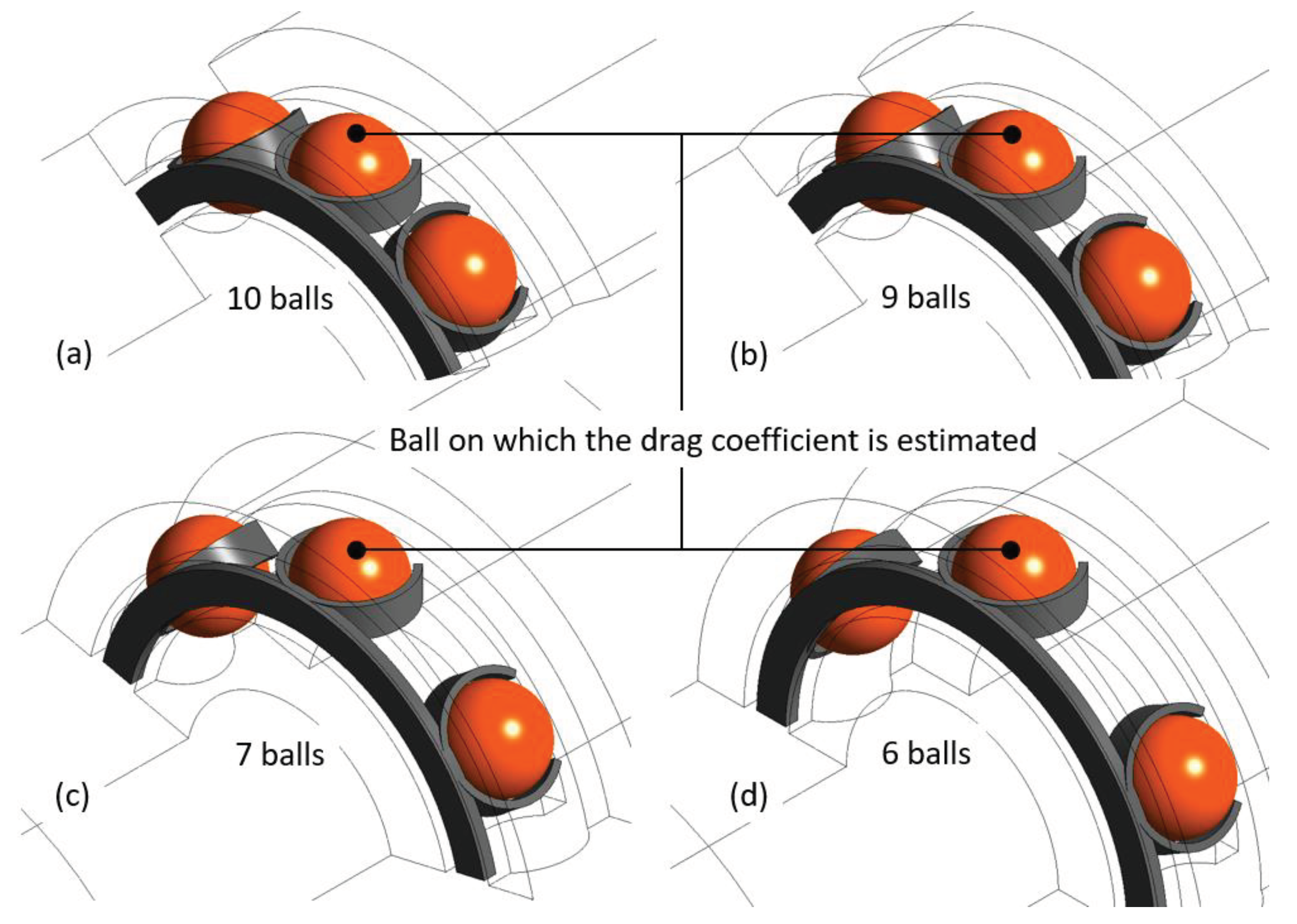
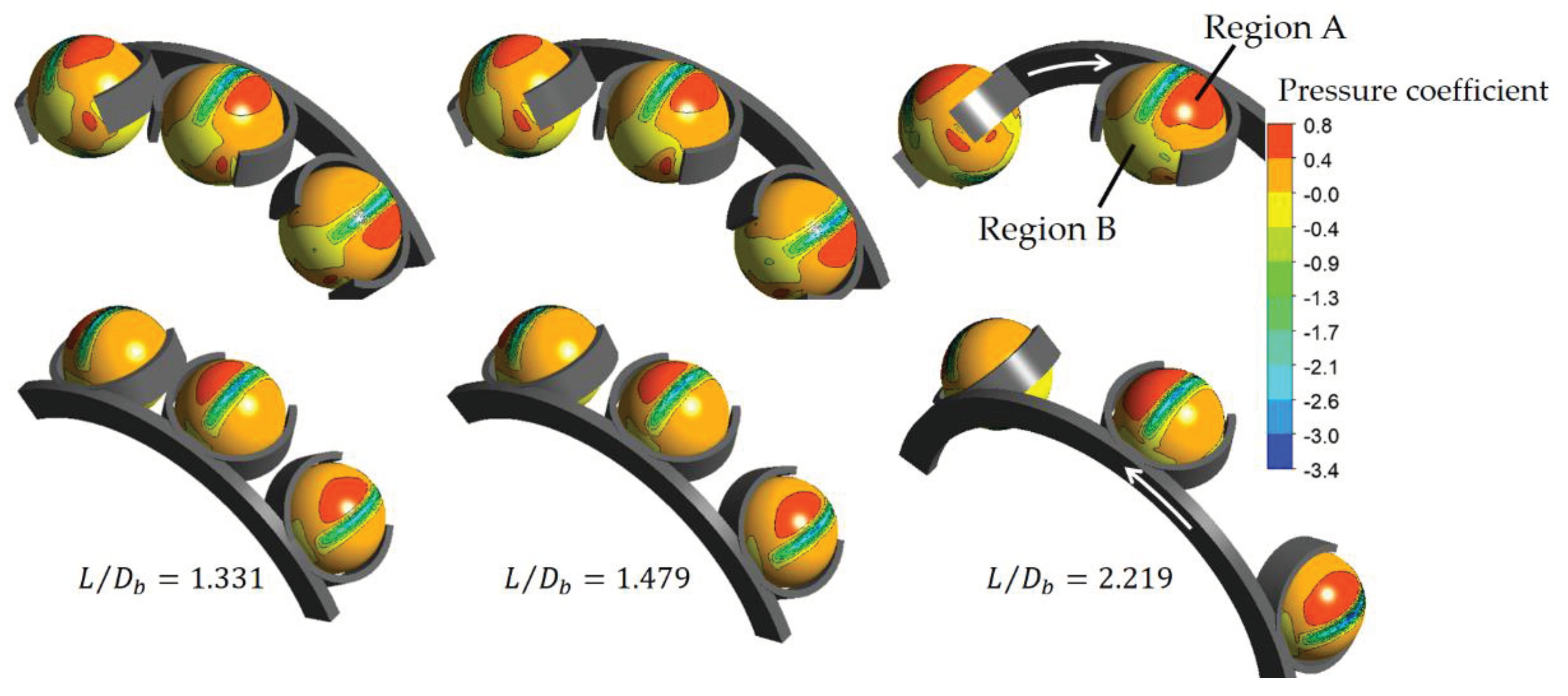
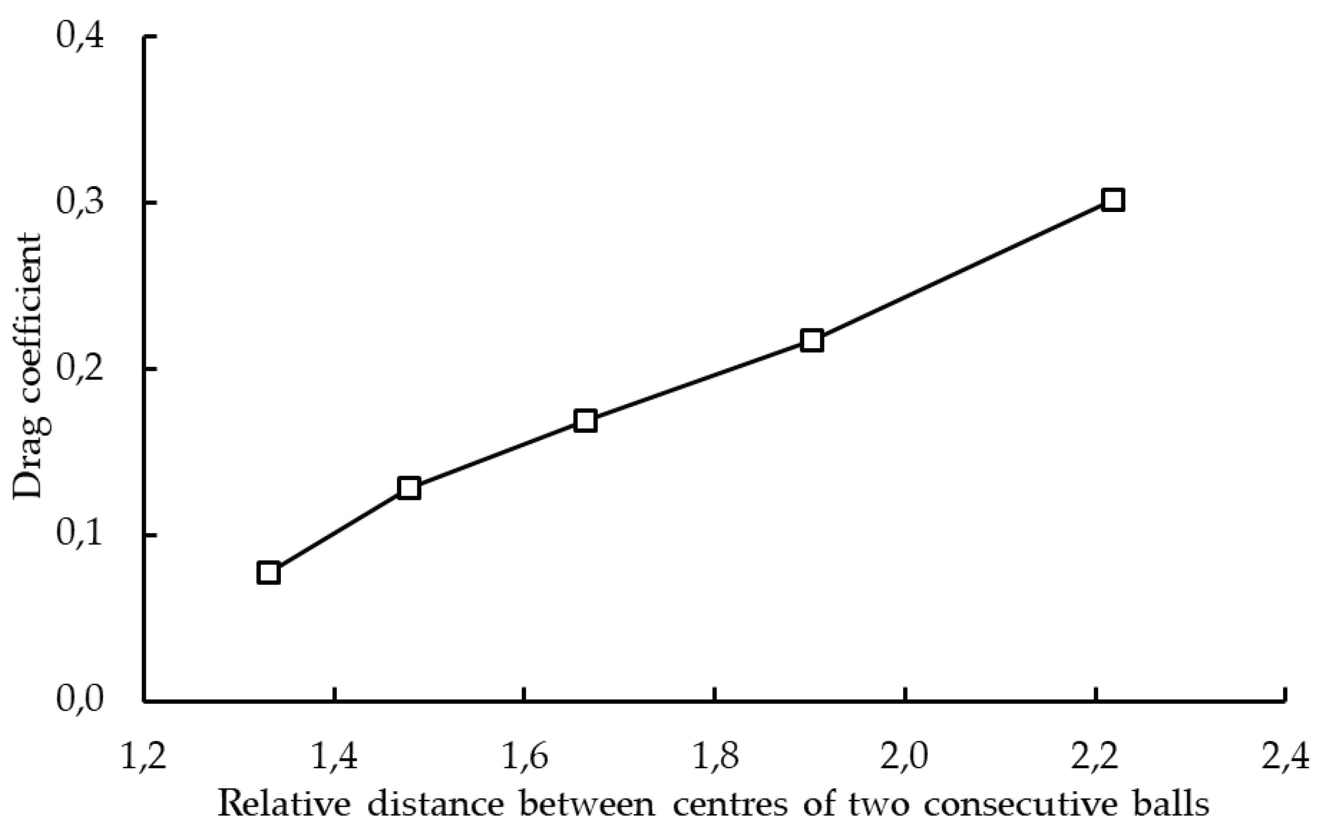
6.1. Influence of the Distance between Two Consecutive Balls
6.2. Influence of the Cage Type
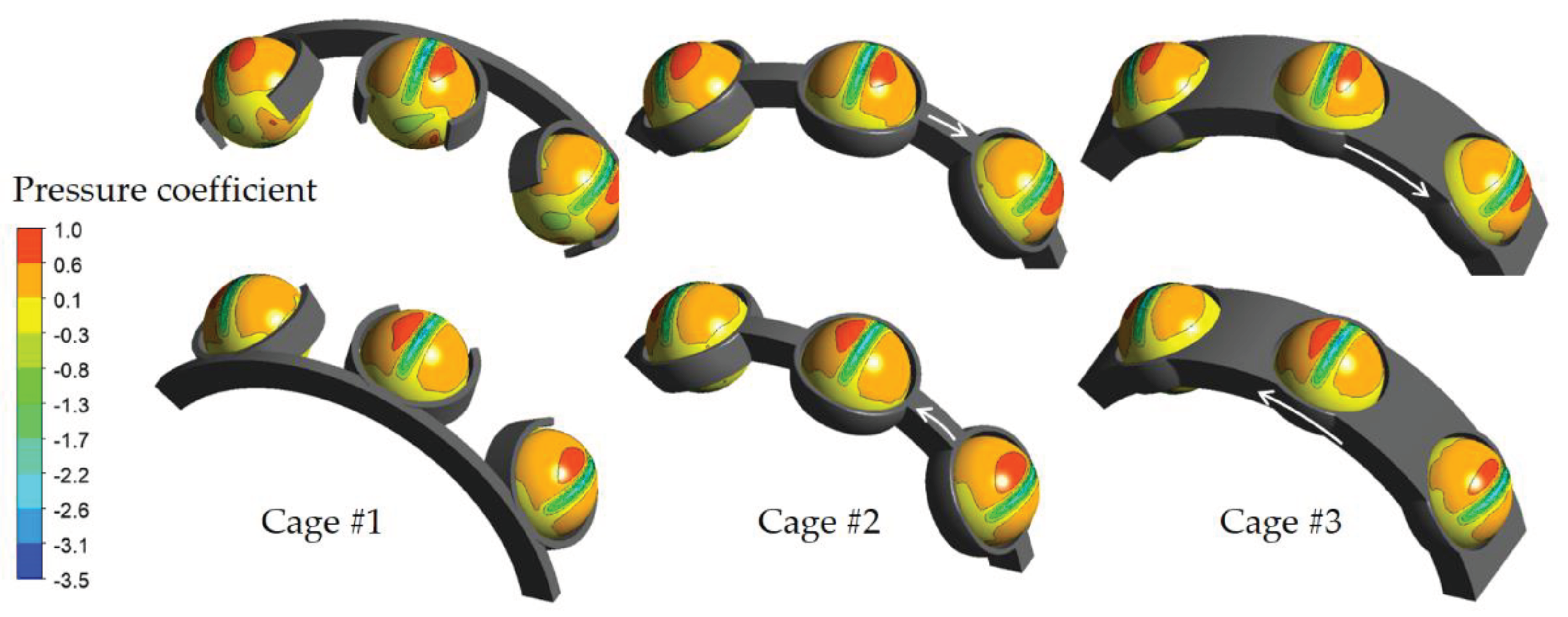
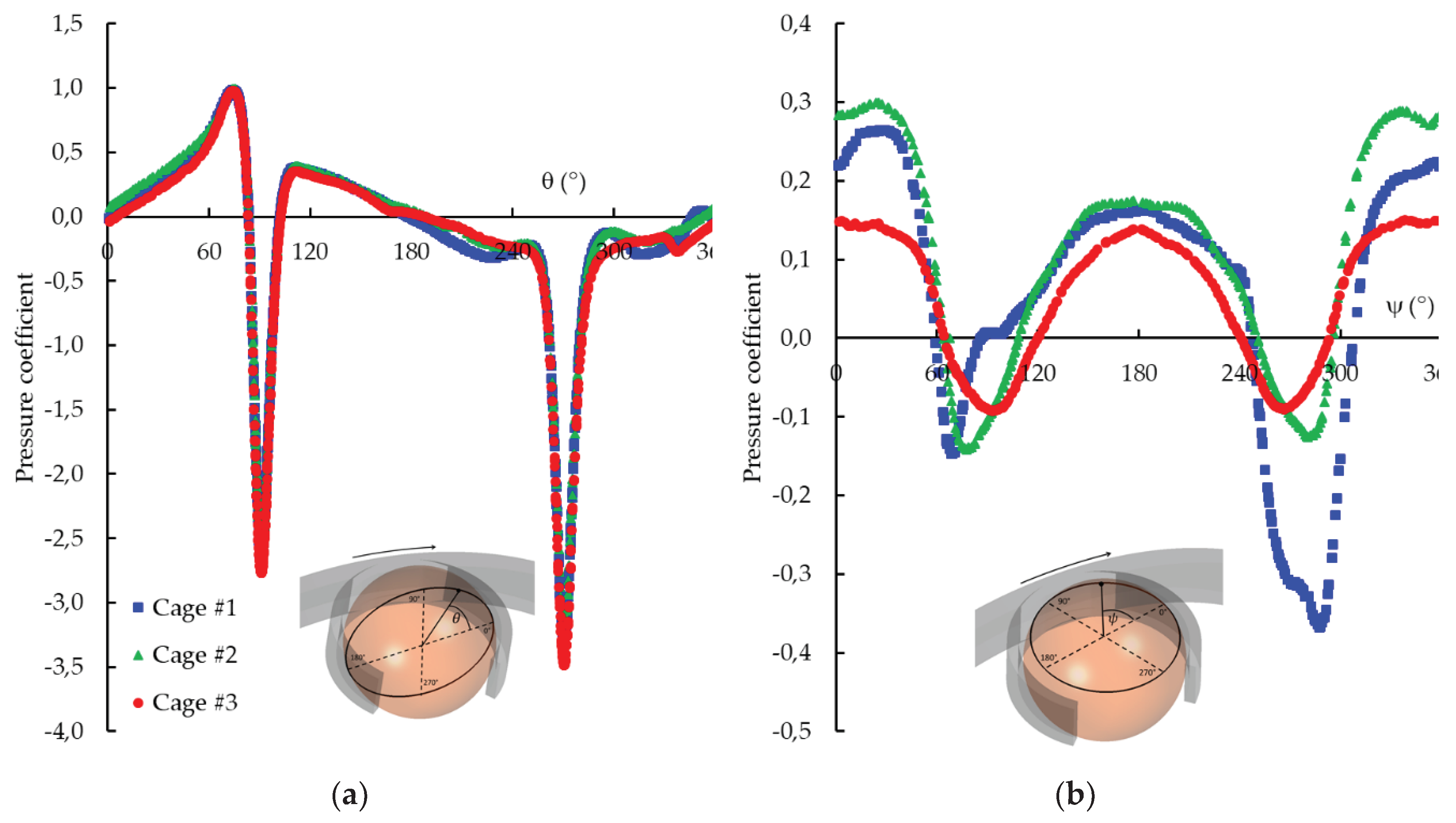
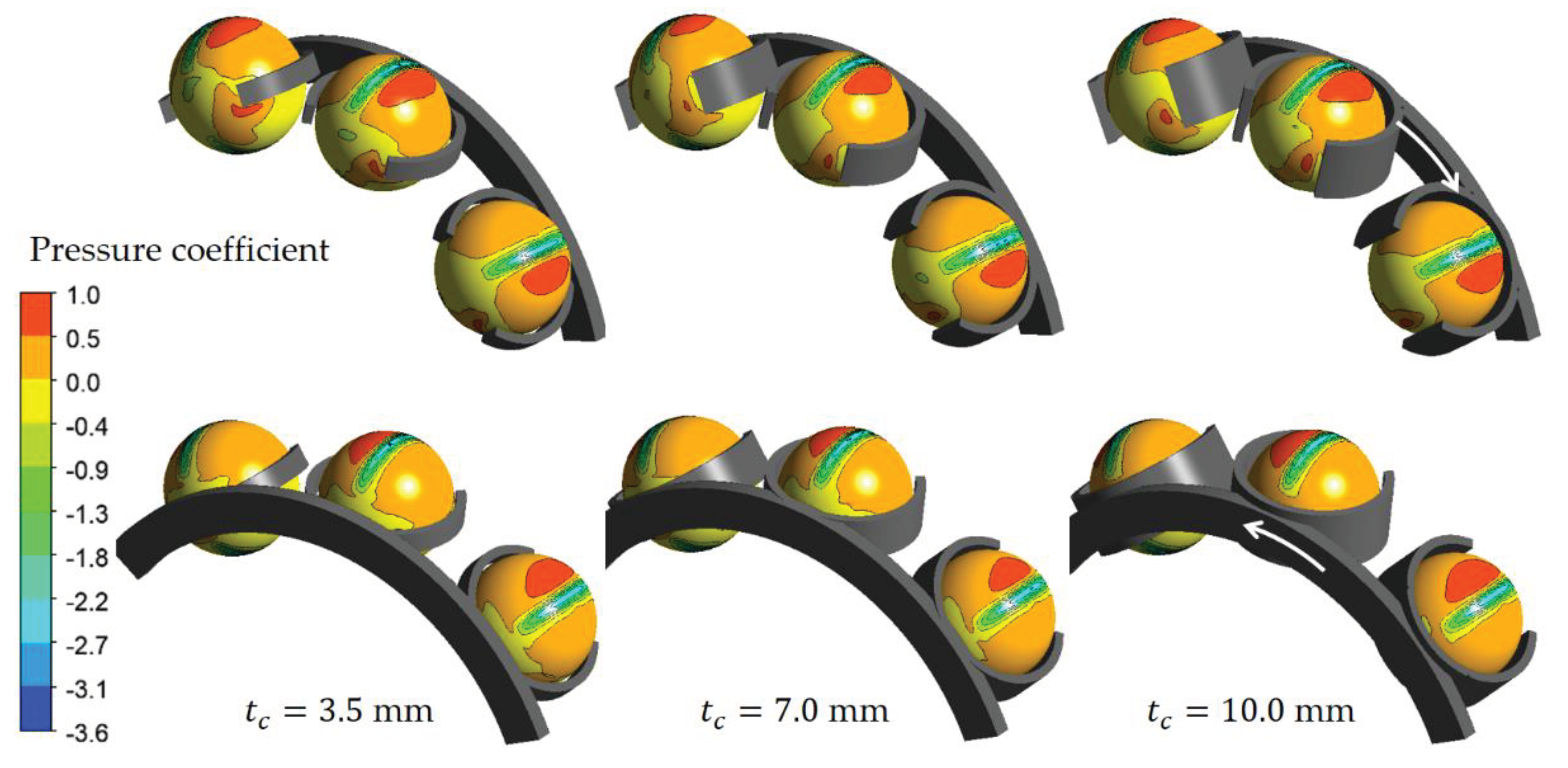
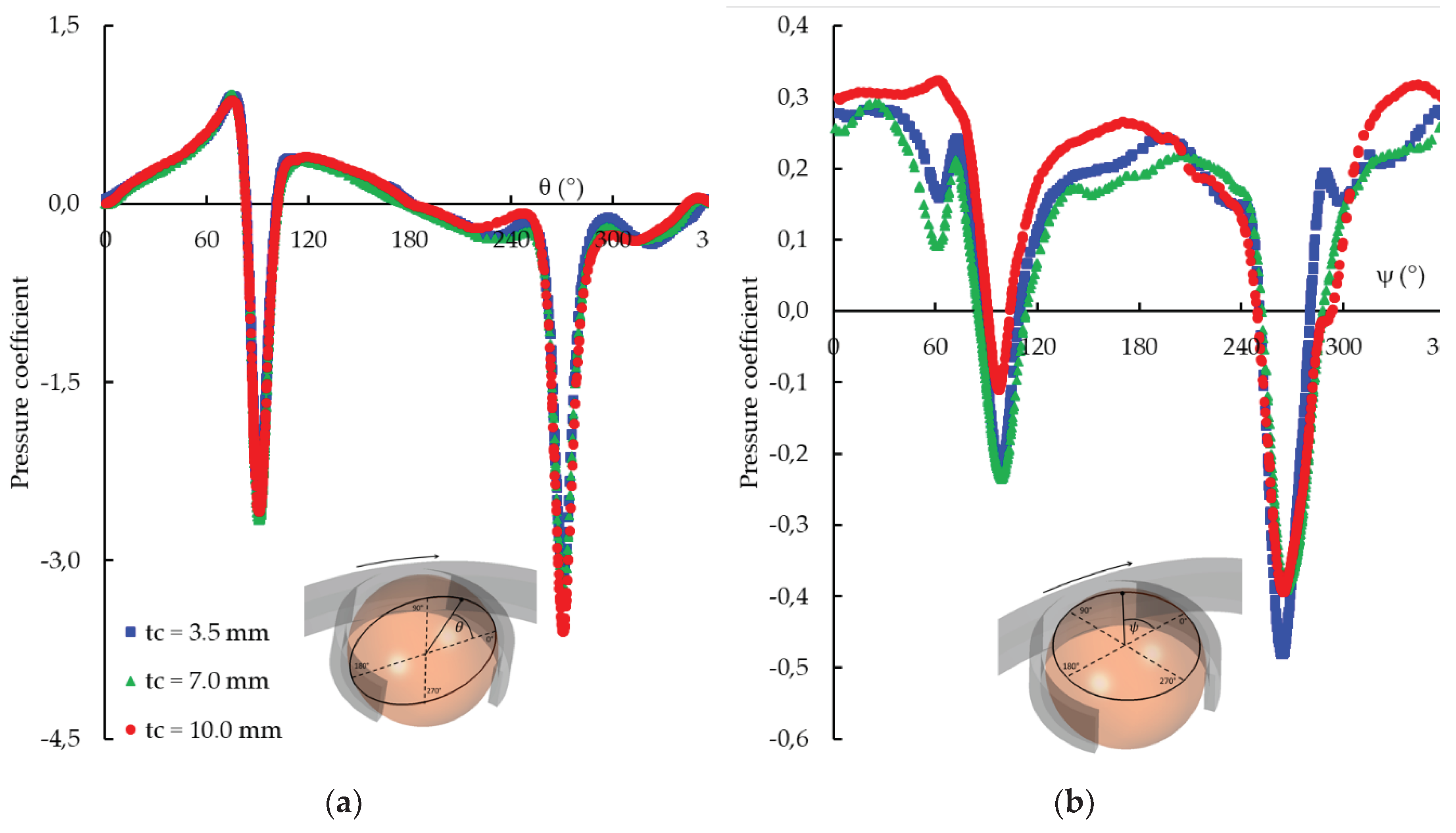
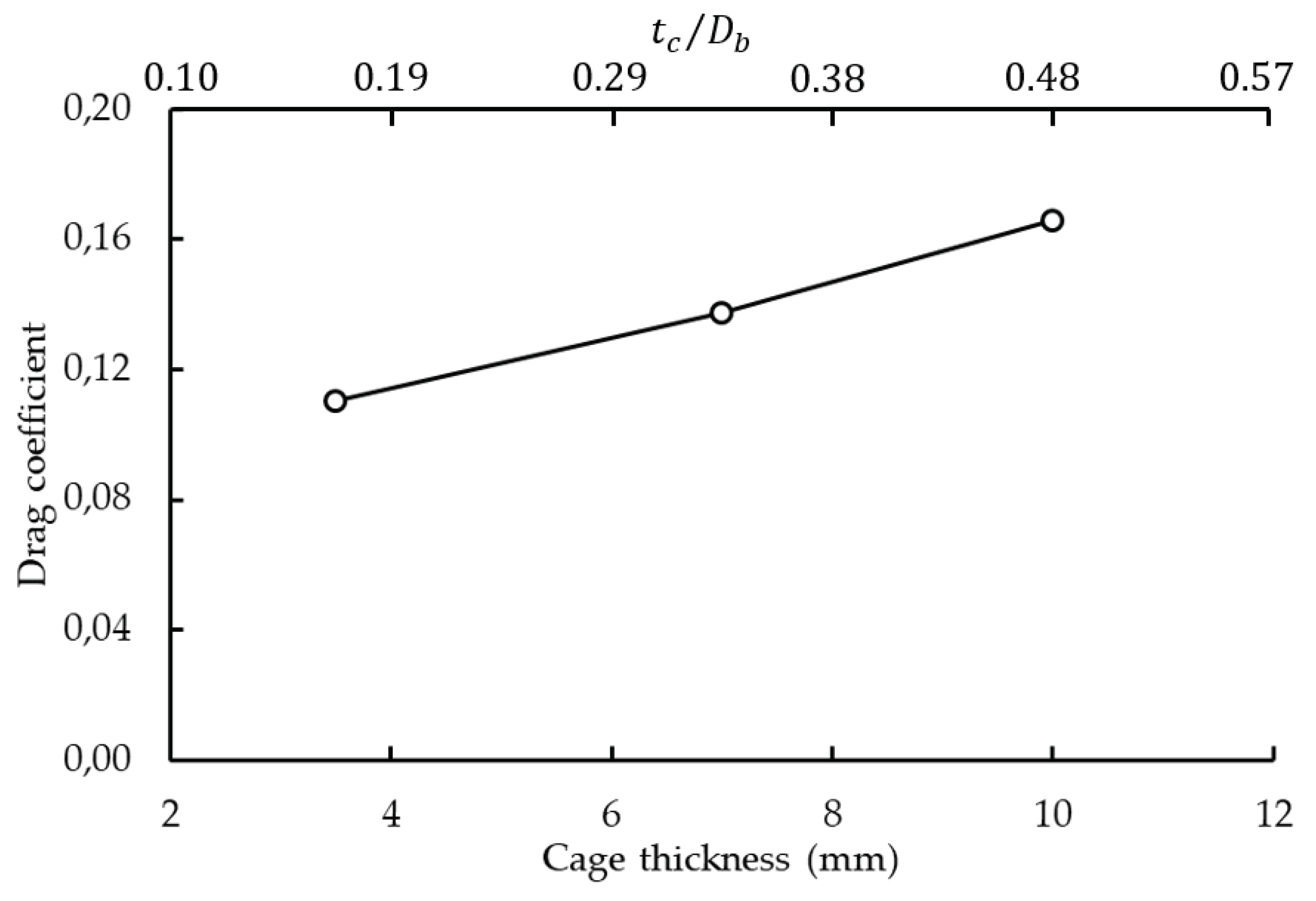
6.3. Influence of the Cage Thickness
7. Conclusion
Author Contributions
Funding
Conflicts of Interest
References
- Transport and environment report 2021 Decarbonising road transport — the role of vehicles, fuels and transport demand. EEA Report No 02/2022.
- Fernandes, C.M.; Marques, P.M.; Martins, R.C.; Seabra, J.H. Gearbox power loss. Part I: Losses in rolling bearings. Tribol. Int. 2015, 88, 298–308. [Google Scholar] [CrossRef]
- Harris, T.A. Rolling bearing analysis, 3rd ed.; John Wiley & Sons Inc.: New York, NY, USA, 1991; ISBN 0. [Google Scholar]
- SKF Group. Rolling bearings; SKF Group: Göteborg, Sweden, 2013; 1375p. [Google Scholar]
- Morales-Espejel, G.E.; Wemekamp, A.W. An engineering drag losses model for rolling bearings. Proc. Inst. Mech. Eng. Part J: J. Eng. Tribol. 2022, 237, 415–430. [Google Scholar] [CrossRef]
- Niel, D.; Changenet, C.; Ville, F.; Octrue, M. Thermomecanical study of high speed rolling element bearing: A simplified approach. Proc. Inst. Mech. Eng. Part J: J. Eng. Tribol. 2017, 233, 541–552. [Google Scholar] [CrossRef]
- Marchesse, Y.; Changenet, C.; Ville, F. Drag Power Loss Investigation in Cylindrical Roller Bearings Using CFD Approach. Tribol. Trans. 2019, 62, 403–411. [Google Scholar] [CrossRef]
- Wang, Z.; Wang, F.; Duan, H.; Wang, W.; Guo, R.; Yu, Q. Numerical Investigation of Oil–Air Flow Inside Tapered Roller Bearings with Oil Bath Lubrication. J. Appl. Fluid Mech. 2024, 17, 273–283. [Google Scholar] [CrossRef]
- Macks, E.F.; Nemeth, Z.N. Lubrication and Cooling Studies of Cylindrical-Roller Bearings at High Speeds. National Advisory Committee for Aeronautics Report 1064. 1952.
- Zaretsky, E.V.; Bamberger, E.N.; Signer, H. Operating characteristics of 120-millimeter-bore ball bearings at 3 million DN. NASA TN-D-7837. 1974.
- Schuller, F.T.; Signer, H.R. Performance of Jet and Inner-Ring-Lubricated 35-Millimeter-Bore Ball Bearings Operating to 2.5 Million DN. NASA TP-1808. 1981.
- Yan, K.; Wang, Y.; Zhu, Y.; Hong, J.; Zhai, Q. Investigation on heat dissipation characteristic of ball bearing cage and inside cavity at ultra high rotation speed. Tribol. Int. 2016, 93, 470–481. [Google Scholar] [CrossRef]
- Rumbarger, J.H.; Filetti, E.G.; Gubernick, D. Gas Turbine Engine Mainshaft Roller Bearing-System Analysis. J. Lubr. Technol. 1973, 95, 401–416. [Google Scholar] [CrossRef]
- Nelias, D. Influence de la lubrification sur la puissance dissipee dans les roulements à rouleaux cylindriques. Revue Française de Mécanique. 1994, 2, 143–154. [Google Scholar]
- Concli, F.; Gorla, C. CFD simulation of power losses and lubricant flows in gearboxes. In Proceedings of the American Gear Manufacturers Association Fall Technical Meeting 2017, Columbus, OH, USA, 22–24 October 2017. [Google Scholar]
- Hill, M.J.; Kunz, R.F.; Medvitz, R.B.; Handschuh, R.F.; Long, L.N.; Noack, R.W.; Morris, P.J. CFD Analysis of Gear Windage Losses: Validation and Parametric Aerodynamic Studies. J. Fluids Eng. 2011, 133, 031103. [Google Scholar] [CrossRef]
- Fondelli, T.; Andreini, A.; Facchini, B. Numerical Investigation on Windage Losses of High-Speed Gears in Enclosed Configuration. AIAA J. 2018, 56, 1910–1921. [Google Scholar] [CrossRef]
- Concli, F.; Conrado, E.; Gorla, C. Analysis of power losses in an industrial planetary speed reducer: Measurements and computational fluid dynamics calculations. Proc. Inst. Mech. Eng. Part J: J. Eng. Tribol. 2013, 228, 11–21. [Google Scholar] [CrossRef]
- Hirt, C.W.; Nichols, B.D. Volume of fluid (VOF) method for the dynamics of free boundaries. J. Comput. Phys. 1981, 39, 201–225. [Google Scholar] [CrossRef]
- Hildebrand, L.; Dangl, F.; Sedlmair, M.; Lohner, T.; Stahl, K. CFD analysis on the oil flow of a gear stage with guide plate.CONFERENCE NAME, LOCATION OF CONFERENCE, COUNTRYDATE OF CONFERENCE; pp. 677–694.
- Concli, F.; Mastrone, M.N. Advanced Lubrication Simulations of an Entire Test Rig: Optimization of the Nozzle Orientation to Maximize the Lubrication Capability. Lubricants 2023, 11, 300. [Google Scholar] [CrossRef]
- Hu, J.; Wu, W.; Wu, M.; Yuan, S. Numerical investigation of the air–oil two-phase flow inside an oil-jet lubricated ball bearing. Int. J. Heat Mass Transf. 2014, 68, 85–93. [Google Scholar] [CrossRef]
- Wu, W.; Hu, J.; Yuan, S.; Hu, C. Numerical and experimental investigation of the stratified air-oil flow inside ball bearings. Int. J. Heat Mass Transf. 2016, 103, 619–626. [Google Scholar] [CrossRef]
- Liebrecht, J.; Si, X.; Sauer, B.; Schwarze, H. Investigation of Drag and Churning Losses on Tapered Roller Bearings. 2015, 61, 399–408. [CrossRef]
- Adeniyi, A.A.; Morvan, H.P.; Simmons, K.A. A Multiphase Computational Study of Oil-Air Flow Within the Bearing Sector of Aeroengines. ASME Turbo Expo 2015: Turbine Technical Conference and Exposition. LOCATION OF CONFERENCE, CanadaDATE OF CONFERENCE;
- Peterson, W.; Russell, T.; Sadeghi, F.; Berhan, M.T. Experimental and analytical investigation of fluid drag losses in rolling element bearings. Tribol. Int. 2021, 161, 107106. [Google Scholar] [CrossRef]
- W. Peterson, T. Russel, F. Sadeghi, M.T. Berhan, L.E. Stacke, and J. Stahl. A CFD investigation of lubricant flow in deep groove ball beargings. Tribology International, 2021, 154, 15 p.
- Arya, U.; Peterson, W.; Sadeghi, F.; Meinel, A.; Grillenberger, H. Investigation of oil flow in a ball bearing using Bubble Image Velocimetry and CFD modeling. Tribol. Int. 2023, 177. [Google Scholar] [CrossRef]
- Feldermann, A.; Fischer, D.; Neumann, S.; Jacobs, G. Determination of hydraulic losses in radial cylindrical roller bearings using CFD simulations. Tribology International. 2017, 113, 201. [Google Scholar] [CrossRef]
- Marchesse, Y.; Changenet, C.; Ville, F. Numerical Investigations on Drag Coefficient of Balls in Rolling Element Bearing. Tribol. Trans. 2014, 57, 778–785. [Google Scholar] [CrossRef]
- Ferziger, J.H.; Perić, M. ; Computational Methods for Fluid Dynamics, 3rd ed., Springer-Verlag: Berlin. 2002.
- Menter, F.R. Two-equation eddy-viscosity turbulence models for engineering applications. AIAA J. 1994, 32, 1598–1605. [Google Scholar] [CrossRef]
- Marchesse, Y.; Changenet, C.; Ville, F. ; Numerical investigations of the cage and rings influence on ball drag coefficient. STLE 70th Annual Meeting & Exhibition, Dallas (Texas - USA), -21, 2015. 17 May.



| Bore diameter, (mm) | 55 |
| Outer diameter, (mm) | 120 |
| Mean diameter, (mm) | 89 |
| Width, (mm) | 29 |
| Number of balls | 8 |
| Ball diameter, (mm) | 21 |
| Kinematic viscosity at 40°C (cSt) |
Kinematic viscosity at 100°C (cSt) |
Density at 15°C (kg/m3) |
|---|---|---|
| 36.6 | 7.8 | 864.6 |
| No. of layers | No. of elements in the mesh | |
|---|---|---|
| 1 | 73,617 | 0.76 |
| 2 | 125,862 | 0.93 |
| 3 | 2,499,240 | 0.95 |
| 4 | 4,687,735 | 0.96 |
| 5 | 8,053,854 | − |
| No. of balls | |
|---|---|
| 1 | 0.89 |
| 3 | 0.99 |
| 5 | − |
| Configuration | |
|---|---|
| Three balls in the REB environment | 0.250 |
| Three balls without the REB environment | 0.116 |
| Raceway osculation | |
| 0.187 | |
| -0,087 |
| Cage | |
| #1 | 0.187 |
| 0.116 | |
| #3 | 0.028 |
Disclaimer/Publisher’s Note: The statements, opinions and data contained in all publications are solely those of the individual author(s) and contributor(s) and not of MDPI and/or the editor(s). MDPI and/or the editor(s) disclaim responsibility for any injury to people or property resulting from any ideas, methods, instructions or products referred to in the content. |
© 2024 by the authors. Licensee MDPI, Basel, Switzerland. This article is an open access article distributed under the terms and conditions of the Creative Commons Attribution (CC BY) license (http://creativecommons.org/licenses/by/4.0/).


